CN113914180A - Energy-saving municipal road intelligence scavenging machine - Google Patents
Energy-saving municipal road intelligence scavenging machine Download PDFInfo
- Publication number
- CN113914180A CN113914180A CN202111193780.2A CN202111193780A CN113914180A CN 113914180 A CN113914180 A CN 113914180A CN 202111193780 A CN202111193780 A CN 202111193780A CN 113914180 A CN113914180 A CN 113914180A
- Authority
- CN
- China
- Prior art keywords
- rod
- fixedly connected
- bevel gear
- plate
- round
- Prior art date
- Legal status (The legal status is an assumption and is not a legal conclusion. Google has not performed a legal analysis and makes no representation as to the accuracy of the status listed.)
- Granted
Links
- 230000002000 scavenging effect Effects 0.000 title claims description 4
- 238000004140 cleaning Methods 0.000 claims abstract description 29
- 241001417527 Pempheridae Species 0.000 claims abstract description 23
- 238000010408 sweeping Methods 0.000 claims abstract description 19
- 230000005540 biological transmission Effects 0.000 claims abstract description 10
- 230000000712 assembly Effects 0.000 claims abstract description 5
- 238000000429 assembly Methods 0.000 claims abstract description 5
- XLYOFNOQVPJJNP-UHFFFAOYSA-N water Substances O XLYOFNOQVPJJNP-UHFFFAOYSA-N 0.000 claims description 33
- 238000003825 pressing Methods 0.000 claims description 29
- 238000009434 installation Methods 0.000 claims description 18
- 238000000926 separation method Methods 0.000 claims description 2
- 238000010009 beating Methods 0.000 claims 1
- 238000000034 method Methods 0.000 abstract description 40
- 230000008569 process Effects 0.000 abstract description 33
- 239000002689 soil Substances 0.000 abstract description 2
- 235000017166 Bambusa arundinacea Nutrition 0.000 description 5
- 235000017491 Bambusa tulda Nutrition 0.000 description 5
- 241001330002 Bambuseae Species 0.000 description 5
- 235000015334 Phyllostachys viridis Nutrition 0.000 description 5
- 239000011425 bamboo Substances 0.000 description 5
- 230000009471 action Effects 0.000 description 3
- 239000000428 dust Substances 0.000 description 2
- 238000001125 extrusion Methods 0.000 description 2
- 230000003068 static effect Effects 0.000 description 2
- 230000004075 alteration Effects 0.000 description 1
- 230000009286 beneficial effect Effects 0.000 description 1
- 238000010276 construction Methods 0.000 description 1
- 230000000694 effects Effects 0.000 description 1
- 238000005516 engineering process Methods 0.000 description 1
- 239000011521 glass Substances 0.000 description 1
- 238000004519 manufacturing process Methods 0.000 description 1
- 230000007246 mechanism Effects 0.000 description 1
- 230000004048 modification Effects 0.000 description 1
- 238000012986 modification Methods 0.000 description 1
- 238000005096 rolling process Methods 0.000 description 1
- 238000006467 substitution reaction Methods 0.000 description 1
Images


Classifications
-
- E—FIXED CONSTRUCTIONS
- E01—CONSTRUCTION OF ROADS, RAILWAYS, OR BRIDGES
- E01C—CONSTRUCTION OF, OR SURFACES FOR, ROADS, SPORTS GROUNDS, OR THE LIKE; MACHINES OR AUXILIARY TOOLS FOR CONSTRUCTION OR REPAIR
- E01C23/00—Auxiliary devices or arrangements for constructing, repairing, reconditioning, or taking-up road or like surfaces
- E01C23/06—Devices or arrangements for working the finished surface; Devices for repairing or reconditioning the surface of damaged paving; Recycling in place or on the road
- E01C23/08—Devices or arrangements for working the finished surface; Devices for repairing or reconditioning the surface of damaged paving; Recycling in place or on the road for roughening or patterning; for removing the surface down to a predetermined depth high spots or material bonded to the surface, e.g. markings; for maintaining earth roads, clay courts or like surfaces by means of surface working tools, e.g. scarifiers, levelling blades
- E01C23/085—Devices or arrangements for working the finished surface; Devices for repairing or reconditioning the surface of damaged paving; Recycling in place or on the road for roughening or patterning; for removing the surface down to a predetermined depth high spots or material bonded to the surface, e.g. markings; for maintaining earth roads, clay courts or like surfaces by means of surface working tools, e.g. scarifiers, levelling blades using power-driven tools, e.g. vibratory tools
- E01C23/0855—Devices or arrangements for working the finished surface; Devices for repairing or reconditioning the surface of damaged paving; Recycling in place or on the road for roughening or patterning; for removing the surface down to a predetermined depth high spots or material bonded to the surface, e.g. markings; for maintaining earth roads, clay courts or like surfaces by means of surface working tools, e.g. scarifiers, levelling blades using power-driven tools, e.g. vibratory tools moved rectilinearly, e.g. scabblers
-
- E—FIXED CONSTRUCTIONS
- E01—CONSTRUCTION OF ROADS, RAILWAYS, OR BRIDGES
- E01C—CONSTRUCTION OF, OR SURFACES FOR, ROADS, SPORTS GROUNDS, OR THE LIKE; MACHINES OR AUXILIARY TOOLS FOR CONSTRUCTION OR REPAIR
- E01C23/00—Auxiliary devices or arrangements for constructing, repairing, reconditioning, or taking-up road or like surfaces
- E01C23/06—Devices or arrangements for working the finished surface; Devices for repairing or reconditioning the surface of damaged paving; Recycling in place or on the road
- E01C23/08—Devices or arrangements for working the finished surface; Devices for repairing or reconditioning the surface of damaged paving; Recycling in place or on the road for roughening or patterning; for removing the surface down to a predetermined depth high spots or material bonded to the surface, e.g. markings; for maintaining earth roads, clay courts or like surfaces by means of surface working tools, e.g. scarifiers, levelling blades
- E01C23/085—Devices or arrangements for working the finished surface; Devices for repairing or reconditioning the surface of damaged paving; Recycling in place or on the road for roughening or patterning; for removing the surface down to a predetermined depth high spots or material bonded to the surface, e.g. markings; for maintaining earth roads, clay courts or like surfaces by means of surface working tools, e.g. scarifiers, levelling blades using power-driven tools, e.g. vibratory tools
- E01C23/088—Rotary tools, e.g. milling drums
- E01C23/0885—Rotary tools, e.g. milling drums with vertical or steeply inclined rotary axis
-
- Y—GENERAL TAGGING OF NEW TECHNOLOGICAL DEVELOPMENTS; GENERAL TAGGING OF CROSS-SECTIONAL TECHNOLOGIES SPANNING OVER SEVERAL SECTIONS OF THE IPC; TECHNICAL SUBJECTS COVERED BY FORMER USPC CROSS-REFERENCE ART COLLECTIONS [XRACs] AND DIGESTS
- Y02—TECHNOLOGIES OR APPLICATIONS FOR MITIGATION OR ADAPTATION AGAINST CLIMATE CHANGE
- Y02E—REDUCTION OF GREENHOUSE GAS [GHG] EMISSIONS, RELATED TO ENERGY GENERATION, TRANSMISSION OR DISTRIBUTION
- Y02E10/00—Energy generation through renewable energy sources
- Y02E10/50—Photovoltaic [PV] energy
Landscapes
- Engineering & Computer Science (AREA)
- Mechanical Engineering (AREA)
- Mining & Mineral Resources (AREA)
- Architecture (AREA)
- Civil Engineering (AREA)
- Structural Engineering (AREA)
- Cleaning Of Streets, Tracks, Or Beaches (AREA)
Abstract
The invention discloses an energy-saving municipal road intelligent sweeper, which comprises a sweeper, a sweeping assembly and a mounting plate for driving the sweeping assembly to retract and retract, wherein the sweeping assembly comprises a rotating shaft, a sweeping brush and a motor for driving the sweeping brush to rotate, the motor is mounted on the upper surface of the mounting plate, one end of the rotating shaft is fixedly connected with the output end of the motor, the other end of the rotating shaft penetrates through the lower surface of the mounting plate and is fixedly connected with the sweeping brush, the left side of the lower surface of the mounting plate is fixedly connected with a mounting box, a knocking assembly is arranged in front of the sweeping assembly, the sweeper drives the sweeping assembly to sweep the ground in the working process, meanwhile, the rotating shaft drives a crankshaft to rotate through a transmission assembly, the crankshaft drives a plurality of knocking assemblies on a movable plate to move up and down through a connecting rod in the rotating process, and soil on the road surface is separated from the ground through the knocking assembly, thereby through cleaning the cleaner that subassembly will the road surface clearance.
Description
Technical Field
The invention relates to the technical field of municipal cleaning equipment, in particular to an energy-saving municipal road intelligent sweeper.
Background
The municipal roads are public infrastructure which is arranged in planning and construction ranges of urban areas, towns and villages and is based on urban life matching. At present, the cleaning of municipal roads is generally completed by using a sweeper, the sweeper is an integrated garbage sweeper combining sweeping and dust collection, has the advantages of high working efficiency, low cleaning cost, high safety performance, high economic return rate and the like, is widely applied to the cleaning of various large, medium and small urban roads, changes the traditional method that the cleaning of the municipal roads is mainly performed manually or mechanically, and improves the working efficiency.
Earth can often be shed in the highway section that engineering vehicle passed through, but later subaerial earth can be on the road through rolling of vehicle and pedestrian futilely hard, because the cleaning brush of intelligence scavenging machine is generally softer, can't thoroughly clear away subaerial mud piece, and clean effect is not good.
Disclosure of Invention
The invention aims to provide an energy-saving municipal road intelligent sweeper to solve the problems in the background technology.
In order to achieve the purpose, the invention provides the following technical scheme: energy-saving municipal road intelligence is clear
Sweeping machine, including the motor sweeper, clean the subassembly and be used for driving the mounting panel that the subassembly receive and releases, clean the subassembly including pivot, brush cleaner and be used for driving brush cleaner pivoted motor, the motor is installed at the upper surface of mounting panel, the one end of pivot and the output fixed connection of motor, the other end of pivot runs through the lower surface of mounting panel and with brush cleaner fixed connection, the left side fixedly connected with install bin of mounting panel lower surface, it is connected with the bent axle to rotate between the front and back both sides inner wall of install bin, be provided with drive assembly between install bin and the pivot, the pivot drives the bent axle rotation through drive assembly, the below sliding connection of bent axle has the fly leaf, the surface rotation of bent axle is connected with the connecting rod, the bottom of connecting rod is connected with the upper surface rotation of fly leaf, the even fixedly connected with a plurality of subassembly of knocking of lower surface of fly leaf, the bottom end of the knocking component is located outside the installation box, and the knocking component is used for separating mud blocks on the road surface from the ground.
Preferably, the crankshaft comprises a U-shaped rod and first round rods fixed at two ends of the U-shaped rod, and the top end of the connecting rod is rotatably connected with the U-shaped rod.
Preferably, the transmission assembly comprises a second round rod, a first bevel gear, a second bevel gear, a third bevel gear and a fourth bevel gear, one end of the second round rod is located inside the installation box and is fixedly connected with the first bevel gear, the second round rod is rotatably connected with the installation box, the other end of the second round rod is fixedly connected with the second bevel gear, the third bevel gear is fixedly connected to the outer surface of the rotating shaft, the third bevel gear is meshed with the second bevel gear, the fourth bevel gear is fixedly connected to the outer surface of the first round rod, and the fourth bevel gear is meshed with the first bevel gear.
Preferably, both ends all rotate about the second round bar surface and are connected with the fixed block, the upper surface of fixed block and the lower fixed surface of mounting panel are connected.
Preferably, the front side and the rear side of the movable plate are respectively inserted with a guide rod, the bottom end of the guide rod is fixedly connected with the inner bottom wall of the installation box, the top end of the guide rod is fixedly connected with a stop block, and the guide rod is connected with the movable plate in a sliding manner.
Preferably, the subassembly of strikeing includes montant, a movable section of thick bamboo, stopper and first spring, the top of montant and the lower fixed surface of fly leaf are connected, install bin and a movable section of thick bamboo run through in proper order and with stopper fixed connection in the bottom of montant, install bin and a movable section of thick bamboo all with montant sliding connection, first spring is located the inside of a movable section of thick bamboo and establishes the surface at the montant, the lower surface of a movable section of thick bamboo is provided with the pressure plate subassembly, the inside fixed mounting of install bin has the fixed plate, every the inside of montant all is provided with the cavity, slidable mounting has the piston in the cavity, the up end of piston is fixed with the piston rod, the tip of piston rod with fixed plate fixed connection.
Preferably, the pressing plate assembly comprises four pressing plates and a plurality of protrusions, the protrusions are uniformly and fixedly connected to the lower surfaces of the pressing plates, and the pressing plates are movably connected with the movable barrel through auxiliary assemblies.
Preferably, the auxiliary assembly comprises a round block, a push plate and a conical block, the round block is positioned in the middle of the movable cylinder, the bottom end of the push plate is fixedly connected with the upper surface of the pressing plate, the push plate is slidably connected between the round block and the inner wall of the movable cylinder through a sliding assembly, the conical block is fixedly connected with the lower surface of the limiting block, a water outlet hole communicated with the cavity is formed in the conical block, a water inlet hole communicated with the water outlet hole is formed in the limiting block, and the water inlet hole is communicated with a water tank arranged in the sweeper through a hose; and one-way valves are arranged in the water outlet hole and the water inlet hole.
Preferably, the sliding assembly comprises a first transverse rod, a second transverse rod and a second spring, the two ends of the first transverse rod and the second transverse rod are fixedly connected between the inner walls of the round block and the movable barrel, the outer surfaces of the first transverse rod and the second transverse rod are sleeved with the push plate, the push plate is slidably connected with the first transverse rod and the second transverse rod, and the outer surface of the first transverse rod is sleeved with the second spring.
Preferably, the second spring is sleeved on the outer surface of the first cross rod.
Compared with the prior art, the invention has the beneficial effects that:
1. when the mud block on the road surface is thick, the conical block moves downwards and extrudes the push plate, and the push plate drives the press plate component to slide on the sliding component, so that the mud block is pushed to be separated from the ground, namely: the vertical rod drives the limiting block to move downwards in the movable barrel and stretch the first spring, the limiting block can drive the conical block to move in the moving process, the conical block extrudes the push plate on the pressing plate in the downward moving process, and the push plate slides on the first transverse rod and the second transverse rod and extrudes the second spring at the moment, so that the push plate drives the pressing plate to push the mud blocks to move;
2. according to the invention, the knocking component is arranged in front of the cleaning component, the sweeper drives the cleaning component to clean the ground in the working process, the rotating shaft drives the crankshaft to rotate through the transmission component, the crankshaft drives the knocking components on the movable plate to move up and down through the connecting rod in the rotating process, and soil on the road surface is separated from the ground through the knocking components, so that the road surface is cleaned more cleanly through the cleaning component, namely: the motor drives the rotating shaft to rotate, the rotating shaft can drive the third bevel gear and the cleaning brush to rotate in the rotating process, the third bevel gear can drive the second round rod to rotate in the rotating process and meshed with the second bevel gear, the second round rod can drive the first bevel gear to rotate in the rotating process, the first bevel gear can drive the first round rod to rotate in the rotating process and meshed with the fourth bevel gear, the first round rod can drive the U-shaped rod to rotate in the rotating process, the crankshaft is formed by the first round rod and the U-shaped rod, the crankshaft drives the movable plate to slide on the guide rod through the connecting rod in the rotating process, the movable plate can drive a plurality of knocking assemblies to move up and down in the sliding process, the pressing plate on the knocking assemblies is firstly contacted with the ground, and the mud blocks can be conveniently knocked to be separated from the road surface through a plurality of bulges on the lower surface of the pressing plate.
3. At the in-process of montant downstream, the piston remains static under the drive of piston rod, thereby make the cavity volume increase of piston lower part, cavity and external production atmospheric pressure difference promptly, thereby pass through the leading-in cavity of inlet opening with the water in the water tank along the inlet tube, carry out the in-process that shifts up at the montant afterwards, the piston carries out the downstream for the montant through the piston rod, thereby derive the water in the cavity to the clamp plate subassembly along the apopore on, thereby carry out moist softening to the earth on road surface, smash with the impact extrusion of convenient clamp plate subassembly, thereby improve the cleaning efficiency and the quality of earth.
Drawings
FIG. 1 is a schematic perspective view of the present invention;
FIG. 2 is a schematic view of the sweeping assembly of the present invention;
FIG. 3 is a schematic structural view of the transmission assembly of the present invention;
FIG. 4 is a schematic cross-sectional perspective view of the mounting box of the present invention;
FIG. 5 is a schematic structural view of a multiple rapper assembly of the present invention;
FIG. 6 is a schematic cross-sectional view of a knocking assembly according to the present invention;
FIG. 7 is a schematic structural view of the platen assembly of the present invention;
fig. 8 is a schematic sectional structure view of the installation box of the present invention.
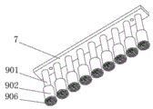
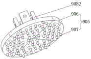
In the figure: 1. a sweeper; 2. a sweeping assembly; 201. a rotating shaft; 202. cleaning with a brush; 203. a motor; 3. mounting a plate; 4. installing a box; 5. a crankshaft; 6. a transmission assembly; 7. a movable plate; 8. a connecting rod; 9. a knocking component; 501. a U-shaped rod; 502. a first round bar; 601. a second round bar; 602. a first bevel gear; 603. a second bevel gear; 604. a third bevel gear; 605. a fourth bevel gear; 606. a fixed block; 701. a guide bar; 702. a stopper; 901. a vertical rod; 902. a movable barrel; 903. a limiting block; 904. a first spring; 905. a platen assembly; 906. a pressing plate; 907. a protrusion; 908. an auxiliary component; 9081. a round block; 9082. pushing the plate; 9083. a conical block; 9084. a sliding assembly; 9085. a first cross bar; 9086. a second cross bar; 9087. a second spring; 10. a fixing plate; 11. a piston; 12. a piston rod; 13. a fixing plate; 14. a water outlet hole; 15. a water inlet hole; 16. a hose.
Detailed Description
The technical solutions in the embodiments of the present invention will be clearly and completely described below with reference to the drawings in the embodiments of the present invention, and it is obvious that the described embodiments are only a part of the embodiments of the present invention, and not all of the embodiments. All other embodiments, which can be derived by a person skilled in the art from the embodiments given herein without making any creative effort, shall fall within the protection scope of the present invention.
Referring to fig. 1-8, an energy-saving type intelligent sweeper for municipal roads comprises a sweeper truck 1,
The cleaning assembly 2 and the mounting plate 3 used for driving the cleaning assembly 2 to retract and retract are included, the cleaning assembly 2 comprises a rotating shaft 201, a cleaning brush 202 and a motor 203 used for driving the cleaning brush 202 to rotate, the motor 203 is mounted on the upper surface of the mounting plate 3, one end of the rotating shaft 201 is fixedly connected with the output end of the motor 203, the other end of the rotating shaft 201 penetrates through the lower surface of the mounting plate 3 and is fixedly connected with the cleaning brush 202, the motor 203 drives the rotating shaft 201 to rotate, and the rotating shaft 201 drives the cleaning brush 202 to clean the ground in the rotating process;
the left side fixedly connected with install bin 4 of 3 lower surfaces of mounting panel, it is connected with bent axle 5 to rotate between the both sides inner wall around install bin 4, be provided with drive assembly 6 between install bin 4 and the pivot 201, pivot 201 passes through drive assembly 6 and drives bent axle 5 rotatory, bent axle 5's below sliding connection has fly leaf 7, bent axle 5's surface rotates and is connected with connecting rod 8, connecting rod 8's bottom and fly leaf 7's upper surface rotate to be connected, bent axle 5 can drive fly leaf 7 through connecting rod 8 at rotatory in-process and reciprocate, the even fixedly connected with of lower surface of fly leaf 7 a plurality of subassembly 9 that strikes, the bottom of subassembly 9 is located the outside of install bin 4, strike subassembly 9 and be used for making mud piece and the ground separation on the road surface.
The crankshaft 5 comprises a U-shaped rod 501 and first round rods 502 fixed at two ends of the U-shaped rod 501, the top end of the connecting rod 8 is rotatably connected with the U-shaped rod 501, the first round rods 502 can drive the U-shaped rod 501 to rotate in the rotating process, and the connecting rod 8 can move up and down by forming an eccentric mechanism through the first round rods 502 and the U-shaped rod 501;
meanwhile, the transmission assembly 6 comprises a second round bar 601, a first bevel gear 602, one end of a second round bar 601 is positioned inside the installation box 4 and is fixedly connected with a first bevel gear 602, the second round bar 601 is rotatably connected with the installation box 4, the other end of the second round bar 601 is fixedly connected with the second bevel gear 603, the third bevel gear 604 is fixedly connected with the outer surface of the rotating shaft 201, the third bevel gear 604 is meshed with the second bevel gear 603, the fourth bevel gear 605 is fixedly connected with the outer surface of the first round bar 502, the fourth bevel gear 605 is meshed with the first bevel gear 602, the third bevel gear 604 is meshed with the second bevel gear 603 in the rotating process to drive the second round bar 601 to rotate, the second round bar 601 can drive the first bevel gear 602 to rotate in the rotating process, and the first bevel gear 602 is meshed with the fourth bevel gear 605 in the rotating process to drive the first round bar 502 to rotate;
the left end and the right end of the outer surface of the second round rod 601 are rotatably connected with fixing blocks 606, the upper surface of each fixing block 606 is fixedly connected with the lower surface of the mounting plate 3, and the fixing blocks 606 are arranged to enable the second round rod 601 to rotate more stably, so that the transmission of the second round rod 601 is facilitated;
meanwhile, the front side and the rear side of the movable plate 7 are respectively inserted with a guide rod 701, the bottom end of the guide rod 701 is fixedly connected with the inner bottom wall of the installation box 4, the top end of the guide rod 701 is fixedly connected with a stop block 702, the guide rod 701 is connected with the movable plate 7 in a sliding manner, the movable plate 7 is more stably moved by the guide rod 701, and the movable plate 7 is prevented from being rubbed with the installation box 4;
in addition, the knocking component 9 includes a vertical rod 901, a movable cylinder 902, a limiting block 903 and a first spring 904, the top end of the vertical rod 901 is fixedly connected with the lower surface of the movable plate 7, the bottom end of the vertical rod 901 sequentially penetrates through the installation box 4 and the movable cylinder 902 and is fixedly connected with the limiting block 903, both the installation box 4 and the movable cylinder 902 are slidably connected with the vertical rod 901, the first spring 904 is located inside the movable cylinder 902 and is sleeved on the outer surface of the vertical rod 901, the lower surface of the movable cylinder 902 is provided with a pressing plate component 905, the vertical rod 901 can drive the limiting block 903 to move downwards in the movable cylinder 902 and stretch the first spring 904, therefore, the vibration of the pressure plate assembly 905 is buffered, a fixing plate 13 is fixedly installed inside the installation box 4, a cavity is formed inside each vertical rod 901, a piston 11 is slidably installed in each cavity, a piston rod 12 is fixed on the upper end face of each piston 11, and the end of each piston rod 12 is fixedly connected with the fixing plate 13;
meanwhile, the pressing plate assembly 905 comprises four pressing plates 906 and a plurality of protrusions 907, the protrusions 907 are uniformly and fixedly connected to the lower surface of the pressing plates 906, the pressing plates 906 are movably connected with the movable barrel 902 through the auxiliary assembly 908, the pressing plates 906 are firstly contacted with the ground, and the mud blocks are conveniently broken through the protrusions 907 on the lower surface of the pressing plates 906 and separated from the road surface;
the auxiliary assembly 908 comprises a round block 9081, a push plate 9082 and a conical block 9083, the round block 9081 is located in the middle of the movable cylinder 902, the bottom end of the push plate 9082 is fixedly connected with the upper surface of the pressing plate 906, the push plate 9082 is slidably connected between the round block 9081 and the inner wall of the movable cylinder 902 through a sliding assembly 9084, the conical block 9083 is fixedly connected to the lower surface of the limiting block 903, the limiting block 903 can drive the conical block 9083 to move in the moving process, the conical block 9083 presses the push plate 9082 on the pressing plate 906 in the downward moving process, the push plate 9082 drives the pressing plate 906 to push the mud block to move to be separated from the ground, a water outlet 14 communicated with the cavity is formed in the conical block 9083, a water inlet 15 communicated with the water outlet 14 is formed in the limiting block 903, and the water inlet 15 is communicated with a water tank installed inside the sweeper 1 through a hose 16; one-way valves are arranged in the water outlet hole 14 and the water inlet hole 15, so that the water inlet hole can only guide water into the cavity, and the water outlet hole 14 can only guide water out of the pressure plate assembly 905;
the sliding assembly 9084 comprises a first cross rod 9085, a second cross rod 9086 and a second spring 9087, two ends of the first cross rod 9085 and two ends of the second cross rod 9086 are fixedly connected between the round block 9081 and the inner wall of the movable barrel 902, the push plate 9082 is sleeved on the outer surfaces of the first cross rod 9085 and the second cross rod 9086, the push plate 9082 is slidably connected with the first cross rod 9085 and the second cross rod 9086, the second spring 9087 is sleeved on the outer surface of the first cross rod 9085, the push plate 9082 slides on the first cross rod 9085 and the second cross rod 9086 and extrudes the second spring 9087, the push plate 9082 can move more stably through the first cross rod 9085 and the second cross rod 9086, and the push plate 9082 can be reset when the knocking assembly 9 moves upwards.
Principle of road sweeper: the sweeper 1 drives the sweeping component 2 on the mounting plate 3 to sweep dust on a road surface, at the moment, the motor 203 drives the rotating shaft 201 to rotate, the rotating shaft 201 can drive the third bevel gear 604 and the sweeping brush 202 to rotate in the rotating process, the third bevel gear 604 is meshed with the second bevel gear 603 in the rotating process to drive the second round bar 601 to rotate, the second round bar 601 can drive the first bevel gear 602 to rotate in the rotating process, the first bevel gear 602 is meshed with the fourth bevel gear 605 in the rotating process to drive the first round bar 502 to rotate, the first round bar 502 can drive the U-shaped bar 501 to rotate in the rotating process, as the first round bar 502 and the U-shaped bar 501 form the crankshaft 5, at the moment, the crankshaft 5 drives the movable plate 7 to slide on the guide rod 701 through the connecting rod 8 in the rotating process, the movable plate 7 can drive the plurality of components 9 to move up and down in the sliding process, at the moment, the pressing plate 906 on the knocking assembly 9 is firstly contacted with the ground, the mud block is conveniently broken to be separated from the road surface through the plurality of protrusions 907 on the lower surface of the pressing plate 906, when the mud block is thick, the vertical rod 901 drives the limiting block 903 to move downwards in the movable barrel 902 and stretch the first spring 904, the limiting block 903 can drive the conical block 9083 to move in the moving process, the conical block 9083 presses the push plate 9082 on the pressing plate 906 in the downward moving process, at the moment, the push plate 9082 slides on the first transverse rod 9085 and the second transverse rod 9086 and presses the second spring 9087, so that the push plate 9082 drives the pressing plate 906 to push the mud block to move to be separated from the ground, and finally, the cleaning brush 202 is used for cleaning in the rotating process, in the downward moving process of the vertical rod 901, the piston 11 is kept static under the driving of the piston rod 12, so that the volume of a cavity at the lower part of the piston 11 is increased, namely, the air pressure of the cavity is different from the outside, thereby pass through the leading-in cavity of inlet opening 15 with the water in the water tank along the inlet tube in, carry out the in-process that shifts up at montant 901 afterwards, piston 11 carries out downstream for montant 901 through piston rod 12 to lead out the water in the cavity to pressure plate assembly 905 along apopore 14 on, thereby carry out moist softening to the earth on road surface, in order to make things convenient for pressure plate assembly 905's impact extrusion to strike the bits of broken glass, thereby improve the cleaning efficiency and the quality of earth.
It is noted that, herein, relational terms such as first and second, and the like may be used solely to distinguish one entity or action from another entity or action without necessarily requiring or implying any actual such relationship or order between such entities or actions. Also, the terms "comprises," "comprising," or any other variation thereof, are intended to cover a non-exclusive inclusion, such that a process, method, article, or apparatus that comprises a list of elements does not include only those elements but may include other elements not expressly listed or inherent to such process, method, article, or apparatus.
Although embodiments of the present invention have been shown and described, it will be appreciated by those skilled in the art that changes, modifications, substitutions and alterations can be made in these embodiments without departing from the principles and spirit of the invention, the scope of which is defined in the appended claims and their equivalents.
Claims (10)
1. The utility model provides an energy-saving town road intelligence scavenging machine which characterized in that includes:
a sweeper (1), a cleaning component (2) and a mounting plate (3) for driving the cleaning component (2) to retract and release,
the cleaning assembly (2) comprises a rotating shaft (201), a cleaning brush (202) and a motor (203) for driving the cleaning brush (202) to rotate, the motor (203) is installed on the upper surface of the installing plate (3), one end of the rotating shaft (201) is fixedly connected with the output end of the motor (203), and the other end of the rotating shaft (201) penetrates through the lower surface of the installing plate (3) and is fixedly connected with the cleaning brush (202);
the left side fixedly connected with install bin (4) of mounting panel (3) lower surface, it is connected with bent axle (5) to rotate between the front and back both sides inner wall of install bin (4), be provided with transmission assembly (6) between install bin (4) and pivot (201), pivot (201) are rotatory through transmission assembly (6) drive bent axle (5), the below sliding connection of bent axle (5) has fly leaf (7), the surface of bent axle (5) rotates and is connected with connecting rod (8), the bottom of connecting rod (8) is connected with the upper surface rotation of fly leaf (7), the even fixedly connected with of lower surface of fly leaf (7) beats subassembly (9), the bottom of beating subassembly (9) is located the outside of install bin (4), it is used for making mud piece and ground separation on the road surface to beat subassembly (9).
2. The energy-saving municipal road intelligent sweeping machine according to claim 1, characterized in that: the crankshaft (5) comprises a U-shaped rod (501) and first round rods (502) fixed at two ends of the U-shaped rod (501), and the top end of the connecting rod (8) is rotatably connected with the U-shaped rod (501).
3. The energy-saving municipal road intelligent sweeping machine according to claim 1, characterized in that: the transmission assembly (6) comprises a second round rod (601), a first bevel gear (602), a second bevel gear (603), a third bevel gear (604) and a fourth bevel gear (605), one end of the second round rod (601) is located inside the installation box (4) and fixedly connected with the first bevel gear (602), the second round rod (601) is rotatably connected with the installation box (4), the other end of the second round rod (601) is fixedly connected with the second bevel gear (603), the third bevel gear (604) is fixedly connected to the outer surface of the rotating shaft (201), the third bevel gear (604) is meshed with the second bevel gear (603), the fourth bevel gear (605) is fixedly connected to the outer surface of the first round rod (502), and the fourth bevel gear (605) is meshed with the first bevel gear (602).
4. The energy-saving municipal road intelligent sweeper of claim 3, wherein: both ends are all rotated and are connected with fixed block (606) about second round bar (601) surface, the upper surface of fixed block (606) and the lower fixed surface of mounting panel (3) are connected.
5. The energy-saving municipal road intelligent sweeping machine according to claim 1, characterized in that: the front side and the rear side of the movable plate (7) are respectively inserted with a guide rod (701), the bottom end of the guide rod (701) is fixedly connected with the inner bottom wall of the installation box (4), the top end of the guide rod (701) is fixedly connected with a stop block (702), and the guide rod (701) is connected with the movable plate (7) in a sliding mode.
6. The energy-saving municipal road intelligent sweeping machine according to claim 1, characterized in that: the knocking component (9) comprises a vertical rod (901), a movable cylinder (902), a limiting block (903) and a first spring (904), the top end of the vertical rod (901) is fixedly connected with the lower surface of the movable plate (7), the bottom end of the vertical rod (901) sequentially penetrates through an installation box (4) and the movable cylinder (902) and is fixedly connected with the limiting block (903), the installation box (4) and the movable cylinder (902) are both in sliding connection with the vertical rod (901), the first spring (904) is located inside the movable cylinder (902) and sleeved on the outer surface of the vertical rod (901), a pressing plate component (905) is arranged on the lower surface of the movable cylinder (902), a fixing plate (13) is fixedly installed inside the installation box (4), a cavity is arranged inside each vertical rod (901), a piston (11) is slidably installed in the cavity, and a piston rod (12) is fixed on the upper end face of the piston (11), the end part of the piston rod (12) is fixedly connected with the fixing plate (13).
7. The energy-saving municipal road intelligent sweeping machine according to claim 6, characterized in that: the pressing plate assembly (905) comprises four pressing plates (906) and a plurality of protrusions (907), the protrusions (907) are uniformly and fixedly connected to the lower surface of the pressing plates (906), and the pressing plates (906) are movably connected with the movable barrel (902) through auxiliary assemblies (908).
8. The energy-saving municipal road intelligent sweeper of claim 7, wherein: the auxiliary assembly (908) comprises a round block (9081), a push plate (9082) and a conical block (9083), the round block (9081) is located in the middle of the movable cylinder (902), the bottom end of the push plate (9082) is fixedly connected with the upper surface of the press plate (906), the push plate (9082) is connected between the round block (9081) and the inner wall of the movable cylinder (902) in a sliding mode through a sliding assembly (9084), the conical block (9083) is fixedly connected to the lower surface of a limiting block (903), a water outlet (14) communicated with the cavity is formed in the conical block (9083), a water inlet (15) communicated with the water outlet (14) is formed in the limiting block (903), and the water inlet (15) is communicated with a water tank installed inside the sweeper (1) through a hose (16); and one-way valves are arranged in the water outlet hole (14) and the water inlet hole (15).
9. The energy-saving municipal road intelligent sweeper of claim 8, wherein: the sliding assembly (9084) comprises a first cross rod (9085), a second cross rod (9086) and a second spring (9087), two ends of the first cross rod (9085) and the second cross rod (9086) are fixedly connected between the round block (9081) and the inner wall of the movable barrel (902), the push plate (9082) is sleeved on the outer surfaces of the first cross rod (9085) and the second cross rod (9086), the push plate (9082) is connected with the first cross rod (9085) and the second cross rod (9086) in a sliding mode, and the second spring (9087) is sleeved on the outer surface of the first cross rod (9085).
10. The energy-saving municipal road intelligent sweeper of claim 9, wherein: the second spring (9087) is sleeved on the outer surface of the first cross rod (9085).
Priority Applications (1)
| Application Number | Priority Date | Filing Date | Title |
|---|---|---|---|
| CN202111193780.2A CN113914180B (en) | 2021-10-13 | 2021-10-13 | Energy-saving municipal road intelligent sweeper |
Applications Claiming Priority (1)
| Application Number | Priority Date | Filing Date | Title |
|---|---|---|---|
| CN202111193780.2A CN113914180B (en) | 2021-10-13 | 2021-10-13 | Energy-saving municipal road intelligent sweeper |
Publications (2)
| Publication Number | Publication Date |
|---|---|
| CN113914180A true CN113914180A (en) | 2022-01-11 |
| CN113914180B CN113914180B (en) | 2023-08-25 |
Family
ID=79239969
Family Applications (1)
| Application Number | Title | Priority Date | Filing Date |
|---|---|---|---|
| CN202111193780.2A Active CN113914180B (en) | 2021-10-13 | 2021-10-13 | Energy-saving municipal road intelligent sweeper |
Country Status (1)
| Country | Link |
|---|---|
| CN (1) | CN113914180B (en) |
Cited By (1)
| Publication number | Priority date | Publication date | Assignee | Title |
|---|---|---|---|---|
| CN118880788A (en) * | 2024-10-09 | 2024-11-01 | 河南三建美辰建筑科技有限公司 | Road cleaning equipment for environmental protection projects |
Citations (11)
| Publication number | Priority date | Publication date | Assignee | Title |
|---|---|---|---|---|
| JPH0820923A (en) * | 1994-07-07 | 1996-01-23 | Nippon Conveyor Kk | Chewing gum remover |
| CN2823324Y (en) * | 2005-09-14 | 2006-10-04 | 李永慧 | Reciprocating snow cleaning machine |
| RU2355845C1 (en) * | 2007-09-12 | 2009-05-20 | Открытое акционерное общество "Научно-производственная корпорация "Механобр-техника" | Vibrating splitter |
| CN108239949A (en) * | 2017-12-28 | 2018-07-03 | 孝昌县志高智能科技有限公司 | A kind of sanitation worker road garbage clearing and transporting vehicle |
| CN110042914A (en) * | 2019-05-17 | 2019-07-23 | 惠州市水电建筑工程有限公司 | A kind of canal reactor pipe network dredging robot |
| CN111255254A (en) * | 2020-03-13 | 2020-06-09 | 江苏省华建建设股份有限公司 | Ground cleaning device for construction |
| CN211815959U (en) * | 2020-02-01 | 2020-10-30 | 青海交通职业技术学院 | Road and bridge device that opens ice |
| CN212983748U (en) * | 2020-05-13 | 2021-04-16 | 广东中鲁建设有限公司 | Municipal administration road deicing snow melt device |
| CN213061876U (en) * | 2020-05-24 | 2021-04-27 | 安徽水阳江建设工程有限公司 | Snow shoveling equipment for municipal road maintenance |
| CN112900342A (en) * | 2021-03-19 | 2021-06-04 | 义乌市阁涂贸易有限公司 | A instrument for step deicing |
| KR102264435B1 (en) * | 2020-11-23 | 2021-06-14 | 주식회사 셀파코퍼레이션 | Sediment removal apparatus for bridge joint |
-
2021
- 2021-10-13 CN CN202111193780.2A patent/CN113914180B/en active Active
Patent Citations (11)
| Publication number | Priority date | Publication date | Assignee | Title |
|---|---|---|---|---|
| JPH0820923A (en) * | 1994-07-07 | 1996-01-23 | Nippon Conveyor Kk | Chewing gum remover |
| CN2823324Y (en) * | 2005-09-14 | 2006-10-04 | 李永慧 | Reciprocating snow cleaning machine |
| RU2355845C1 (en) * | 2007-09-12 | 2009-05-20 | Открытое акционерное общество "Научно-производственная корпорация "Механобр-техника" | Vibrating splitter |
| CN108239949A (en) * | 2017-12-28 | 2018-07-03 | 孝昌县志高智能科技有限公司 | A kind of sanitation worker road garbage clearing and transporting vehicle |
| CN110042914A (en) * | 2019-05-17 | 2019-07-23 | 惠州市水电建筑工程有限公司 | A kind of canal reactor pipe network dredging robot |
| CN211815959U (en) * | 2020-02-01 | 2020-10-30 | 青海交通职业技术学院 | Road and bridge device that opens ice |
| CN111255254A (en) * | 2020-03-13 | 2020-06-09 | 江苏省华建建设股份有限公司 | Ground cleaning device for construction |
| CN212983748U (en) * | 2020-05-13 | 2021-04-16 | 广东中鲁建设有限公司 | Municipal administration road deicing snow melt device |
| CN213061876U (en) * | 2020-05-24 | 2021-04-27 | 安徽水阳江建设工程有限公司 | Snow shoveling equipment for municipal road maintenance |
| KR102264435B1 (en) * | 2020-11-23 | 2021-06-14 | 주식회사 셀파코퍼레이션 | Sediment removal apparatus for bridge joint |
| CN112900342A (en) * | 2021-03-19 | 2021-06-04 | 义乌市阁涂贸易有限公司 | A instrument for step deicing |
Cited By (1)
| Publication number | Priority date | Publication date | Assignee | Title |
|---|---|---|---|---|
| CN118880788A (en) * | 2024-10-09 | 2024-11-01 | 河南三建美辰建筑科技有限公司 | Road cleaning equipment for environmental protection projects |
Also Published As
| Publication number | Publication date |
|---|---|
| CN113914180B (en) | 2023-08-25 |
Similar Documents
| Publication | Publication Date | Title |
|---|---|---|
| CN111822401A (en) | Photovoltaic panel self-cleaning system of solar street lamp in green city | |
| CN113914180A (en) | Energy-saving municipal road intelligence scavenging machine | |
| CN205685458U (en) | A kind of wood flour retracting device | |
| CN114922034A (en) | Highway engineering road roughness check out test set | |
| CN110821200A (en) | Ceramic tile beautiful seam coating strikes off collection device | |
| CN113789747A (en) | A water spray cleaning device for electric washing and sweeping vehicles | |
| CN219260833U (en) | road sweeping device | |
| CN2804173Y (en) | Road scvenging machine | |
| CN207855637U (en) | Rubbish is swept into structure | |
| CN118048867A (en) | Multifunctional efficient cleaning sweeper | |
| CN118752650A (en) | An impurity recovery structure for plastic recycling | |
| CN214303589U (en) | High leakproofness is thermal-insulated bridge cut-off aluminum alloy window outer drainage structures | |
| CN215562232U (en) | Washing and sweeping vehicle belt cleaning device | |
| CN109853434B (en) | Sound barrier cleaning equipment | |
| CN216040904U (en) | Road environmental protection road sweeper | |
| CN221322160U (en) | Aluminum alloy door and window | |
| CN115845969A (en) | Civil engineering waste material piece sorter | |
| CN214656198U (en) | Anti-interference type road detection vehicle | |
| CN221340241U (en) | Automatic motor sweeper platform that charges | |
| CN216379327U (en) | Building bridge road surface cleaning equipment | |
| CN223317133U (en) | Municipal public works construction road clearing device | |
| CN220117089U (en) | Dust blowing cleaning mechanism for filter cylinder of sweeper | |
| CN106192827B (en) | A kind of Environmental sanitation cleaning vehicle | |
| CN221118365U (en) | A road surface cleaning device for road engineering | |
| CN222094102U (en) | Take clean function's thermal-insulated noise control steel double-layered glued glass |
Legal Events
| Date | Code | Title | Description |
|---|---|---|---|
| PB01 | Publication | ||
| PB01 | Publication | ||
| SE01 | Entry into force of request for substantive examination | ||
| SE01 | Entry into force of request for substantive examination | ||
| TA01 | Transfer of patent application right |
Effective date of registration: 20230728 Address after: No. 6 Kaixuan Road, High tech Zone, Jining City, Shandong Province, 272000 Applicant after: Jining Sao Machinery Co.,Ltd. Address before: 215000 No. 28, Zhongshan East Road, Mudu Town, Wuzhong District, Suzhou City, Jiangsu Province Applicant before: Zhang Qing |
|
| TA01 | Transfer of patent application right | ||
| GR01 | Patent grant | ||
| GR01 | Patent grant |