Drawings
Fig. 1 is a front perspective view of a multi-function baking oven with air frying capability according to an embodiment of the present invention.
Fig. 2 is a front perspective view of the baking oven of fig. 1 with the side walls removed.
FIG. 3 is a front perspective view of the baking oven of FIG. 2 with a portion of the fan shroud removed.
FIG. 4 is a front perspective view of the baking oven of FIG. 3 with the entire fan shroud removed.
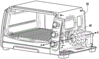
FIG. 5 is a front perspective view of the baking oven of FIG. 4 with the fan shroud and fan removed.
Fig. 6 is a front view of the baking oven of fig. 1 with the door removed and the fan and shroud shown in phantom to illustrate air flow in the cooking cavity and the operating cavity.
Figure 6A is a front view of the frying rack of the baking oven of figure 1, illustrating the "sinking" effect caused by frozen or cold food resting on the grill of the frying rack.
FIG. 7 is a schematic view of a heating system of the baking oven of FIG. 1.
Fig. 8 is a front perspective view of a frying rack of the baking oven of fig. 1.
Fig. 8A is a cross-sectional view of the frying pan taken along line 8A-8A in fig. 8.
FIG. 9 is a partial top perspective view of a fan shroud of the baking oven of FIG. 1.
FIG. 10 is a schematic front view of the fan and shroud of the baking oven of FIG. 1, illustrating the rotation of the fan and the resultant air flow in the shroud.
Figure 11 is a partial front perspective view of a baffle mounted on a sidewall within a cooking cavity of the baking oven of figure 1.
Fig. 12 is a fan shroud for a baking oven according to other embodiments of the present invention.
Figure 13 is a schematic view of an upper duct system for a baking oven according to an additional embodiment of the present invention.
Figure 14 is a schematic diagram of a cooking support and vent actuation system for a baking oven according to an embodiment of the present invention.
Fig. 15 is a schematic diagram of a cooking hob and a switch, which is actuated by inserting the cooking hob, according to an embodiment of the present invention.
Fig. 15A is a front perspective view of a cooking hob with a protrusion for closing a switch according to an additional embodiment of the present invention.
Fig. 15B is a top perspective view of the cooking support of fig. 15A.
FIG. 16 is a front perspective view of a breakaway heat shield system having features for engaging a switch in accordance with a further embodiment of the present invention.
FIG. 17 is a front perspective view of a self-contained heat shield system according to an additional embodiment of the present invention.
FIG. 18 is a front perspective view of the heat shield system of FIG. 17 assembled on the floor of a baking oven.
Figure 19 is a front perspective view of a frying pan and rack for a baking oven according to a further embodiment of the present invention.
Figure 20 is a front perspective view of another frying pan and rack for a baking oven according to a further embodiment of the present invention.
Figure 21 is an enlarged front perspective view of a grill for frying flat pans having different settings to enable the grill to be set at different heights in accordance with an embodiment of the present invention.
Figure 22 is a partially cut-away elevation view of a control cavity of a baking oven according to an additional embodiment of the present invention.
FIG. 23 is a front perspective view, partially in section, of the control chamber of FIG. 22.
FIG. 24 is a rear perspective view, partially in section, of the control chamber of FIG. 22.
Detailed Description
The present invention now will be described more fully hereinafter with reference to the accompanying drawings, in which embodiments of the invention are shown. This invention may, however, be embodied in many different forms and should not be construed as limited to the embodiments set forth herein; rather, these embodiments are provided so that this disclosure will be thorough and complete, and will fully convey the scope of the invention to those skilled in the art.
In the drawings, certain layers, components or features may be exaggerated for clarity, and broken lines illustrate optional features or operations, unless stated otherwise. This invention may, however, be embodied in many different forms and should not be construed as limited to the embodiments set forth herein; rather, these embodiments are provided so that this disclosure will be thorough and complete, and will fully convey the scope of the invention to those skilled in the art.
It will be understood that, although the terms first, second, etc. may be used herein to describe various elements, components, regions, layers and/or sections, these elements, components, regions, layers and/or sections should not be limited by these terms. These terms are only used to distinguish one element, component, region, layer or section from another region, layer or section. Thus, a first element, component, region, layer or section discussed below could be termed a second element, component, region, layer or section without departing from the teachings of the present invention. The order of operations (or steps) is not limited to the order shown in the claims or figures unless specifically indicated otherwise.
Unless otherwise defined, all terms (including technical and scientific terms) used herein have the same meaning as commonly understood by one of ordinary skill in the art to which this invention belongs. It will be further understood that terms, such as those defined in commonly used dictionaries, should be interpreted as having a meaning that is consistent with their meaning in the context of the specification and relevant art and will not be interpreted in an idealized or overly formal sense unless expressly so defined herein. Well-known functions or constructions may not be described in detail for brevity and/or clarity.
The terminology used in the present disclosure is for the purpose of describing particular embodiments only and is not intended to be limiting of the invention. As used in this disclosure, the singular forms "a", "an" and "the" are intended to include the plural forms as well, unless the context clearly indicates otherwise. It will be further understood that the terms "comprises" and/or "comprising," when used in this specification, specify the presence of stated features, integers, steps, operations, elements, and/or components, but do not preclude the presence or addition of one or more other features, integers, steps, operations, elements, components, and/or groups thereof as used in this disclosure, and that the terms "and/or" include any and all combinations of one or more of the associated listed items.
As used in this disclosure, phrases such as "between X and Y" and "between about X and Y" should be interpreted to include X and Y. As used in this disclosure, phrases such as "between about X and Y" mean "between about X and about Y". As used in this disclosure, phrases such as "from about X to Y" mean "from about X to about Y"
Referring now to the drawings, there is illustrated in FIG. 1 a multi-function baking oven, generally designated 10. The bake oven 10 is generally box-shaped and includes a floor 12, side walls 13, 14, a back wall 16, and a top panel 18. The front of the baking oven 10 includes a panel 20 that covers a portion of the front of the device and has a control dial 22 mounted thereon that is connected to a controller 200 (shown in fig. 7). The remainder of the front of the baking oven 10 is covered with a door 24 (shown transparent in fig. 1) that is pivotally attached to the floor 12. A handle 26 is mounted to an upper portion of the door 24 to facilitate opening and closing of the door 24.
As can be seen in fig. 2-5, the inner side wall 28 resides inwardly of the side wall 14 and extends from the inner edge of the panel 20 to the rear wall 16. The bottom panel 12, side walls 13, rear wall 16, top panel 18, door 24 and inner side walls 28 define a cooking cavity 30. The inner wall 28, bottom panel 12, side walls 14, rear wall 16, top panel 18 and face panel 20 define a control chamber 32. Typically, the cooking cavity 30 has a width dimension (between the side walls 13 and the inner wall 28) of about 10 to 14 inches, a depth dimension (from the door 20 to the rear wall 16) of about 10 to 14 inches, and a height (from the floor 12 to the roof 18) of about 6 to 9 inches. As is common in baking ovens, the cooking cavity 30 is wider and/or deeper than it is tall.
Within the cooking cavity 30, the baking oven 10 may have one or more cooking racks. More specifically, a grill-like lower support 34 extends between the side wall 13 and the inner side wall 28. The lower bracket 34 is supported in a slot 36 in the side wall 13 and a set of three non-continuous slots 38 in the inner side wall 28 (see fig. 6). The front member of the bracket 34 is captured by two hooks 40 that are also attached to the door 24 such that opening of the door 24 pulls the lower bracket forward, sliding it within the slots 36, 38. The hook 40 also enables the lower bracket 34 to be completely removed.
As shown in fig. 6, 8 and 8A, a frying stand 40 is shown. The frying pan support 40 may be used in place of the lower support 34 described above. Frying rack 40 includes a wire frame 42 having a lower end 43 configured to fit within the slots 36, 38 described above. A generally rectangular flat disc 44 is mounted to the upper surface of the wire frame 42. Two runners 46 are mounted to the lower surface of the pan 44 and extend longitudinally therebelow. An arcuate heat shield 48 (typically made of painted or galvanized steel) is mounted to each runner 46. A grill 50 (see fig. 8A) is positioned within the flat pan 44 and above the bottom surface of the flat pan 44 to create a gap 52.
In some embodiments, the frying stand 40 can include notches, grooves, protrusions, projections, latches, or other features (see, e.g., fig. 14, 15A, and 15B) that mate with complementary features in the walls 13, 14 to ensure that the frying stand 40 is positioned at the proper height and position within the cooking cavity 30. Proper positioning of the frying support 40 (and the food placed thereon) can provide a more consistent cooking result and prevent food from falling or dripping from the support 40 onto the underlying heating element 100 (discussed below).
Referring now to fig. 6 and 7, the heating elements of the baking oven 10 are shown. More specifically, two elongated heating elements 100 are located in the lower region of the cooking cavity 30 below the support 40. Two elongated heating elements 102 are located in an upper region of the cooking cavity 30. These heating elements 100, 102 are electrically connected such that they are both activated when the bake oven is used for baking or heating. In addition, two elongated supplemental heating elements 104 are also positioned in an upper region of the cooking cavity 30 (e.g., between the heating elements 102), and another supplemental heating element 106 is positioned in the cooking cavity 30 at other locations (e.g., mounted to the inner side wall 28) or in the control cavity 32, as described below. Supplemental heating elements 104, 106 are electrically connected to heating elements 100, 102 (e.g., via switches 110, 112 shown schematically in fig. 7) such that they are activated (e.g., both switches 110, 112 are closed) when bake oven 10 is used in an air-fry mode, but they are not activated (different cooking modes will be discussed below) when bake oven 10 is used in a bake or heat mode.
Referring now to fig. 2-4, within the control cavity 32, the baking oven 10 comprises a recirculation duct 61, within which a fan 60 is mounted. The fan 60 is shown in the present disclosure as a centrifugal impeller fan that is oriented such that it rotates about an axis a that is generally parallel to the inner sidewall 28 (i.e., the axis a extends rearwardly from the front of the baking oven 10 through the hub of the impeller). The recirculation duct 61 also includes a shroud 62 that covers the fan 60. The fan 60 and shroud 62 are configured such that an impeller or other air directing member of the fan 60 draws air from the cooking cavity 30 into the shroud 60 (see fig. 5) through one or more relatively large inlet vents 66 positioned in a lower region of the inner wall 28. In some embodiments, the lower inlet vent 66 is positioned below the level of the cooking surface of the grill 50 of the frying support 40, which can facilitate a desired air flow pattern as described herein. The shield 62 leads to an outlet 64 which delivers air back into the cooking cavity 30 through an upper outlet vent 68 located in an upper region of the inner wall 28. Any or all of the vents 66, 68 may be covered by a screen or filter to prevent food debris or particles from reaching the fan 60 or the shroud 62.
The positioning and orientation of the recirculation duct 61 and in particular the fan 60 and the vents 66, 68 results in the general air flow pattern shown in fig. 6, 6A and 10. More specifically, operation of the fan 60 causes the impeller to rotate in a counterclockwise direction from the vantage point of fig. 6 and 10. This rotation draws air into the shroud 62 through the lower air port 66 and forces the air out through the upper air port 68. This flow pattern has the overall effect that air from the lower region of the cooking cavity 30, below the grill 50 of the frying support 40 (shown by the right-pointing arrow L in fig. 6 and 10), around the fan 60 and up through the shield 62 (see fig. 10), is drawn into the lower vent 66, and is forced out of the upper vent 68, through the upper region of the cooking cavity 30 (shown by the left-pointing arrow U in fig. 6 and 10), and down within the cooking cavity 30. In some cases, there may also be a beneficial "sinking" effect within the cooking cavity 30. Referring to fig. 6A, food resting on the grill 50 of the frying rack 40 is generally cooler than the ambient air surrounding it. This is particularly true of frozen food products, such as frozen french fries. The cooler temperature of the food may produce a natural sink of air (shown by arrow D in fig. 6A), which may enhance the tendency of the air to follow the flow path and in doing so evenly pass over the food on the cooking surface. (it should be understood that additional centrally located vents (also serving as outlets from the shield 62 into the cooking cavity 30) may be desirable for larger baking ovens because their larger cooking cavities are capable of cooking a greater range of food sizes and types.)
In general, conventional baking ovens occupy a relatively large footprint and have a relatively short (height) cooking cavity. In contrast, air fryers tend to have a higher cooking cavity and a smaller footprint. Air fryers are also typically designed to provide a flow of air sufficient in temperature, humidity, volume, and speed to absorb and expel moisture from the food surface. When this airflow is generated with the correct balance of dehydration and heat, it can produce a food with a desirable crispness/texture. The above-described air flow pattern driven by the fan 60 and directed by the shroud 62 can create an environment in which the air flow (which may be 15-25cfm, and in some cases about 20cfm) produces cooking conditions that enable satisfactory frying. The axis of rotation a of fan 60, which is generally parallel to inner wall 28 (i.e., parallel to the front-to-back direction of bake oven 10), may help to create a relatively large, relatively low velocity airflow into and through the food on the cooking surface.
One feature that may improve air flow and thus fry quality is to locate food lower in the cooking cavity 30. Such positioning may tend to equalize the flow of air through the food and/or create a low velocity airflow around the food, while positioning the food away from the high velocity airflow exiting the vents 68. The suction area of the fan 60 is non-jetting and thus creates a large, uniformly dispersed low pressure flow field. As the distance from the food to the spray outlet increases, the more likely it is that the air is evenly spread over the food for even heating. Thus, the food is heated and releases moisture relatively uniformly on all surfaces. Furthermore, because the lower vents 66 are relatively large and the air intake ducts of the shield 62 are likewise large, the velocity of the air flow L is relatively low (particularly the upper vents generally have a lower total open area than the lower vents 66 as compared to the upper vents 68), which may provide desired cooking (i.e., air frying) conditions.
In addition, the motor coils (not specifically shown) of the fan 60 are mounted relatively low in the control cavity 32, which may provide cooling advantages.
Referring now to fig. 9 and 10, a vent 70 is present in the upper surface of the outlet 64 of the shield 62. The vent 70 is covered by a flap plate 72, which flap plate 72 is mounted to the outlet 64 via a hinge 74. In some embodiments, a baffle 76 is located within the outlet 64, just downstream of the vent 70 and is configured to redirect some of the air traveling in the outlet 64 through the vent 70. The flap panel 72 and hinge 74 may be configured such that the flap panel 72 is biased toward the closed position (i.e., covers the vent 70), wherein movement to the open position requires a predetermined amount of positive pressure (e.g., 5psi) through the vent 70. This biasing may be accomplished via the weight of the flap plate 72 itself, a spring-loaded hinge, or another mechanism.
Referring now to fig. 11, the inner surface of the side wall 13 may have mounted thereon one or more baffles 80. These baffles 80 are positioned so that air traveling down the inner surface of the side wall 13 can be slowed and redirected slightly. The baffles 80 may be used to help create the air flow patterns described above. Further, the lower portion of the baffle 80 may be positioned such that a portion of the air flowing down the side wall 13 may be deflected into the gap 52 between the flat pan 44 and the grill 50 (see fig. 8A).
To operate the baking oven 10 in a conventional baking or cooking mode, a user places food on the rack 34 and manipulates one or more of the carousels 22 to the appropriate cooking/baking settings. The dial 22 sends a signal to the controller 200 (which is typically located in the control cavity 32) to activate the heating elements 100, 102 to a desired time/temperature. In some embodiments, heating elements 100, 102 may be 350W heating elements, such that at full power, baking oven 10 generates 1400W of heat to bake or cook. Notably, at full power, the heating elements 100, 102 tend to "glow," which can enhance crispness of the baked surface of the food. The baking oven 10 continues to bake/cook in a conventional manner until the food is finished.
To operate the baking oven 10 in the air-fry mode, the user removes the rack 34, places the frying rack 40 within the cooking cavity 30 and places the food to be fried on the frying rack 40. The user then manipulates one or more of the carousels 22 to a setting suitable for air-frying. The dial 22 sends a signal to the controller 200 to activate the heating elements 100, 102 and the supplemental heating elements 104, 106. However, in the illustrated embodiment, the heating elements 100, 102 are not fully activated; for example, if a 350W heating element is used for the heating elements 100, 102, they may only be activated to 250W, at which level they will not "glow", as described above. Supplemental heating elements 104, 106 provide additional heat; for example, supplemental heating element 104 may be a 250W heating element, and supplemental heating element 108 may be a 185-200W heating element. Thus, when the heating elements 100, 102 are partially activated to 250W, and the supplemental heating elements 104, 106 are at full power, the total wattage of the baking oven is approximately 1700W, which is a typical heat load for an air fryer. However, because none of the heating elements 100, 102, 104, 106 are heated sufficiently to reach a "glowing" state, they do not bake food; instead, the food gradually and continuously loses moisture and becomes hot in a traditional frying manner. Of course, in other embodiments, the total power level may vary (e.g., the total wattage may be between 1100 and 1300W).
It is also worth noting that a heat shield 48 is present on the frying support 40. When the frying stand 40 is in place, each heat shield 48 is positioned directly above a respective heating element 100 such that heat from the heating elements 100 is deflected and does not directly reach the food. As a result, the portion of the food closest to the heating element 100 is not directly "cooked" by the heating element 100, but rather heat from the heating element 100 flows into the airflow L.
Further, when the baking oven 10 is operated in the air-frying mode, the controller 200 activates the fan 60, which creates the above-described air flow pattern. In operation, the airflow generated by the fan 60 generates sufficient pressure to cause the flap plate 72 to pivot upward from the upper surface of the shroud 62, thereby opening the vent 70 and allowing a portion of the airflow to exit through the vent 70. In some embodiments, between about 15 percent and 30 percent of the total gas flow may escape through the vent 70 (e.g., if the gas flow has a flow rate of 20cfm, the portion escaping through the vent 70 may be 3 to 6 cfm). As the vented portion of the airflow escapes the vent 70, it carries moisture that is extracted from the food as it cooks. Accordingly, the vent 70 serves to reduce the humidity in the cooking cavity 30. The reduction in moisture helps produce a food product with a crunchy/textured feel. In some cases, it may be desirable to include additional thermal insulation in the walls of the baking oven and/or to employ materials such as low emissivity (LowE) glass coated with potassium ions in the door to reduce heat loss).
Those skilled in the art will appreciate that the baking oven 10 may take other forms. For example, larger bake oven designs (e.g., bake ovens having cooking cavities between about 1 and 1.4 cubic feet, such as 1.2 cubic feet) may include additional features. As an example, fig. 12 shows an alternative fan shroud 62' as part of the recirculation duct 61. The shield 62 'includes an outlet conduit 64' having two separate outlets: a lower outlet 65 'and an upper outlet 66'. Each outlet 65 ', 66' leads to a suitably positioned vent (not shown here) in the inner wall 28, which vent opens into the cooking cavity 30. A shield of this configuration may be well suited for use in larger baking ovens, for example, that may receive a second frying pan.
As an example of another variation of the baking oven 10, fig. 13 shows a recirculation duct 161, wherein the fan shroud 162 feeds directly into a duct 300 extending above the cooking cavity (and in some embodiments across the entire cooking cavity) and discharges air downwardly into the cooking cavity. The duct 300 includes a vent hole 302 in a lower surface thereof, which opens into the cooking cavity 30. The duct 300 may also have butterfly valve louvers or baffles 304 in its interior to help direct air toward and through the vent holes 302.
As another example of a variation suitable for larger baking oven models, fig. 14 shows a portion of the frame of a relatively deep frying basket 320. A wire protrusion 324 is present on the upper wire rim 322 of the basket 320. The actuator rod 326 is pivotally mounted to a pivot crank 328. The crank 328 is fixed to a cam 330 that is pivotally mounted to the inner wall 28 'of the baking oven 10'. As fry basket 320 slides into slot 332 in inner wall 28', protrusion 324 engages cam 330 and forces it to pivot. This action rotates the crank 328, which in turn extends the actuator rod 326 upward. Upward movement of the actuator rod 326 opens the pivoting flap valve 336 (shown in an open position in fig. 14), which normally covers the dehumidification vent 334 in the conduit 300. The opening of the flap valve 336 can remove additional moisture/water from the cooking cavity during cooking. In this manner, vent 334 remains closed unless until frying basket 320 is inserted into slot 332, thereby ensuring that vent 334 remains closed (presumably for baking and conventional cooking) and vent 334 is open for air frying when frying basket 320 is not in use.
Those skilled in the art will also appreciate that wire projections 324 or similar protrusions, projections, grooves, notches, latches, etc. may serve other functions as well. For example, as shown in fig. 15, 15A and 15B, in some embodiments, an electrical switch 340 may be present on the interior wall 28' of baking oven 10 and positioned such that sliding of fry basket 320 into the appropriate vat activates switch 340. Activation of the switch 340 (typically operatively connected to the controller 200) may allow the air-fry mode to operate (conversely, the air-fry mode may not operate unless the switch 340 is activated). Thus, the combination of protrusion 324 and switch 340 may provide a mechanism that prevents the baking oven from operating in the air fry mode if fry basket 320 is inserted into the wrong vat.
Similarly, if the fry basket (e.g., 40 or 320) is formed as a separate component from the heat shield (such that the heat shields 348 are mounted as a unit 360 on their own separate frame 342, see fig. 16), the heat shield frame 348 may have one or more protrusions that can interact with a switch 350, which in turn activates the air fry mode. This mechanism ensures that (a) the heat shields 348 are in place in the air-fry mode, and (b) they are properly oriented (i.e., they are not inverted). Those skilled in the art will appreciate that other non-electrical protrusions and features may be present on the fry basket 320 and/or the heat shield frame 348 to ensure proper orientation thereof when installed.
Referring now to fig. 17 and 18, the separate heat shield assembly 360' may also be self-contained. The heat shield assembly 360 'includes a wire frame 361 with two lower lateral runners 362 that are well below the height of the heat shield 348'. As can be seen in FIG. 18, the heat shield assembly 360' rests on the floor 12 of the baking oven 10, rather than being mounted in slots in the walls 13, 28.
Referring now to FIG. 19, another embodiment of a flat disc is shown, generally designated 400. The pan 400 may be adapted for food items (e.g., steak, hamburger, chicken, etc.) that are typically cooked in a solid pan like a frying pan, which is designed to have a slightly modified air flow pattern. The flat pan 400 has a bottom surface 402, a front wall 403, side walls 404, 405, and a rear wall 406. A lip 407 extends outwardly from the upper edge of the wall 403 and 406. Grill 410 is positioned above and spaced apart from bottom surface 402. Each of the walls 403 and 406 includes a plurality of small windows 408 located below the level of the grill 410. The vent 408 provides an outlet for air that is directed from the top plate of the bake oven down onto food resting on the grill 410; air descends from the top plate, flows over and around the food, exits the vents 408, continues to flow to the bottom plate of the bake oven and is drawn therefrom into the vents in the interior wall 28 of the bake oven, and enters the fan for recirculation. Thus, this arrangement further promotes the "sinking" caused by the colder food as described above.
Another variation of flat disc 400 is shown in fig. 20 and is designated 500. Flat pan 500 is similar to flat pan 400, having bottom surface 502 and walls 503 and 506, but flat pan 500 does not have vents in the walls as described above. Instead, the front wall 503 is shorter than the other walls 504-506 such that the grill 510 rests above the upper edge of the front wall 503. Air directed from above flows over and around the food, but especially under the food, and exits the pan 500 through the gap 512 formed by the front wall 503 and the grill 510.
Referring now to fig. 21, it can also be seen that grill 510 may include protrusions or "standoffs" 514, 516 that extend above and below the cooking surface of grill 510. Notably, the standoffs 514 are shorter than the standoffs 516, which may enable the grill 510 to be spaced at different heights relative to the bottom surface 502 of the flat pan 500. Different heights may be desired for cooking different foods.
As another example of an alternative embodiment of the present invention, a portion of a baking oven having a control cavity 632 is shown in fig. 22-24. The control cavity 632 employs a recirculation conduit 661 that includes an outer shield 662 having a floor 662a below a lower vent 666, a vertical wall 662b, and a ceiling 662c above an upper vent 668. The side walls 663 (only one side wall 663 is shown here) meet the front and rear edges of the shield 662 to form an enclosure with the inner wall 628. A centrifugal fan 660 is mounted within the enclosure. A partition 669 is mounted above the fan 660 to divide the space within the shield 662 into a lower chamber 672 and an upper chamber 674. Partition 669 includes an opening 671 that serves as an outlet for fan 660. The supplemental heating element 706 is mounted in the upper chamber 674 (in particular, the supplemental heating element 104 within the cooking cavity described above may be omitted in this embodiment). A conduit 676 (see fig. 24) is mounted to the rear surface of the rear sidewall 663, covers the window 675 in the rear sidewall 663, and serves as a passageway between the upper chamber 674 and the atmosphere outside the bake oven. Vanes 678 are present on inner wall 628 to direct air through upper vent 668 and in some cases deflect the air sufficiently to reduce its exit velocity.
As can be seen in fig. 23, when the baking oven is operated in the air-frying mode, rotation of the fan 660 (counterclockwise from the vantage point of fig. 22 and 23) draws air from the cooking cavity 630 through the lower vent 666 and into the lower chamber 672. The fan 660 draws this air and discharges it into the upper chamber 674 through the openings 671 in the partition 669. From there, most of the air exits back into the cooking cavity 630 through the upper vent 668. As described above, to reduce the humidity in the air stream, a portion of the air in the upper chamber 674 exits the bake oven through the duct 676. In addition, the air in the upper chamber 674 is heated by the supplemental heater 706 before exiting the upper vent 668. In this embodiment, the total wattage of the baking oven in the air-fry mode may be about 1200W (e.g., each of the 350W heating elements 100, 102 may be heated to 250W to avoid "glowing" and the supplemental heating element 706 may provide additional 185-200W of heat).
The foregoing is illustrative of the present invention and is not to be construed as limiting thereof. Although exemplary embodiments of this invention have been described, those skilled in the art will readily appreciate that many modifications are possible in the exemplary embodiments without materially departing from the novel teachings and advantages of this invention. Accordingly, all such modifications are intended to be included within the scope of this invention as defined in the claims. The invention is defined by the following claims, with equivalents of the claims to be included therein.