CN113840709A - Manufacturing method and injection molding system - Google Patents
Manufacturing method and injection molding system Download PDFInfo
- Publication number
- CN113840709A CN113840709A CN202080036272.0A CN202080036272A CN113840709A CN 113840709 A CN113840709 A CN 113840709A CN 202080036272 A CN202080036272 A CN 202080036272A CN 113840709 A CN113840709 A CN 113840709A
- Authority
- CN
- China
- Prior art keywords
- mold
- injection molding
- molding
- injection
- operation position
- Prior art date
- Legal status (The legal status is an assumption and is not a legal conclusion. Google has not performed a legal analysis and makes no representation as to the accuracy of the status listed.)
- Granted
Links
Images


Classifications
-
- B—PERFORMING OPERATIONS; TRANSPORTING
- B29—WORKING OF PLASTICS; WORKING OF SUBSTANCES IN A PLASTIC STATE IN GENERAL
- B29C—SHAPING OR JOINING OF PLASTICS; SHAPING OF MATERIAL IN A PLASTIC STATE, NOT OTHERWISE PROVIDED FOR; AFTER-TREATMENT OF THE SHAPED PRODUCTS, e.g. REPAIRING
- B29C45/00—Injection moulding, i.e. forcing the required volume of moulding material through a nozzle into a closed mould; Apparatus therefor
- B29C45/03—Injection moulding apparatus
- B29C45/04—Injection moulding apparatus using movable moulds or mould halves
- B29C45/0408—Injection moulding apparatus using movable moulds or mould halves involving at least a linear movement
- B29C45/0416—Injection moulding apparatus using movable moulds or mould halves involving at least a linear movement co-operating with fixed mould halves
-
- B—PERFORMING OPERATIONS; TRANSPORTING
- B29—WORKING OF PLASTICS; WORKING OF SUBSTANCES IN A PLASTIC STATE IN GENERAL
- B29C—SHAPING OR JOINING OF PLASTICS; SHAPING OF MATERIAL IN A PLASTIC STATE, NOT OTHERWISE PROVIDED FOR; AFTER-TREATMENT OF THE SHAPED PRODUCTS, e.g. REPAIRING
- B29C45/00—Injection moulding, i.e. forcing the required volume of moulding material through a nozzle into a closed mould; Apparatus therefor
- B29C45/17—Component parts, details or accessories; Auxiliary operations
- B29C45/40—Removing or ejecting moulded articles
- B29C45/42—Removing or ejecting moulded articles using means movable from outside the mould between mould parts, e.g. robots
-
- B—PERFORMING OPERATIONS; TRANSPORTING
- B29—WORKING OF PLASTICS; WORKING OF SUBSTANCES IN A PLASTIC STATE IN GENERAL
- B29C—SHAPING OR JOINING OF PLASTICS; SHAPING OF MATERIAL IN A PLASTIC STATE, NOT OTHERWISE PROVIDED FOR; AFTER-TREATMENT OF THE SHAPED PRODUCTS, e.g. REPAIRING
- B29C45/00—Injection moulding, i.e. forcing the required volume of moulding material through a nozzle into a closed mould; Apparatus therefor
- B29C45/17—Component parts, details or accessories; Auxiliary operations
- B29C45/72—Heating or cooling
- B29C45/7207—Heating or cooling of the moulded articles
-
- B—PERFORMING OPERATIONS; TRANSPORTING
- B29—WORKING OF PLASTICS; WORKING OF SUBSTANCES IN A PLASTIC STATE IN GENERAL
- B29C—SHAPING OR JOINING OF PLASTICS; SHAPING OF MATERIAL IN A PLASTIC STATE, NOT OTHERWISE PROVIDED FOR; AFTER-TREATMENT OF THE SHAPED PRODUCTS, e.g. REPAIRING
- B29C45/00—Injection moulding, i.e. forcing the required volume of moulding material through a nozzle into a closed mould; Apparatus therefor
- B29C45/17—Component parts, details or accessories; Auxiliary operations
- B29C45/72—Heating or cooling
- B29C45/73—Heating or cooling of the mould
-
- B—PERFORMING OPERATIONS; TRANSPORTING
- B29—WORKING OF PLASTICS; WORKING OF SUBSTANCES IN A PLASTIC STATE IN GENERAL
- B29C—SHAPING OR JOINING OF PLASTICS; SHAPING OF MATERIAL IN A PLASTIC STATE, NOT OTHERWISE PROVIDED FOR; AFTER-TREATMENT OF THE SHAPED PRODUCTS, e.g. REPAIRING
- B29C45/00—Injection moulding, i.e. forcing the required volume of moulding material through a nozzle into a closed mould; Apparatus therefor
- B29C45/17—Component parts, details or accessories; Auxiliary operations
- B29C45/40—Removing or ejecting moulded articles
- B29C45/42—Removing or ejecting moulded articles using means movable from outside the mould between mould parts, e.g. robots
- B29C2045/425—Single device for unloading moulded articles and loading inserts into the mould
-
- B—PERFORMING OPERATIONS; TRANSPORTING
- B29—WORKING OF PLASTICS; WORKING OF SUBSTANCES IN A PLASTIC STATE IN GENERAL
- B29C—SHAPING OR JOINING OF PLASTICS; SHAPING OF MATERIAL IN A PLASTIC STATE, NOT OTHERWISE PROVIDED FOR; AFTER-TREATMENT OF THE SHAPED PRODUCTS, e.g. REPAIRING
- B29C45/00—Injection moulding, i.e. forcing the required volume of moulding material through a nozzle into a closed mould; Apparatus therefor
- B29C45/17—Component parts, details or accessories; Auxiliary operations
- B29C45/40—Removing or ejecting moulded articles
- B29C45/42—Removing or ejecting moulded articles using means movable from outside the mould between mould parts, e.g. robots
- B29C2045/4266—Robot grippers movable along three orthogonal axes
-
- B—PERFORMING OPERATIONS; TRANSPORTING
- B29—WORKING OF PLASTICS; WORKING OF SUBSTANCES IN A PLASTIC STATE IN GENERAL
- B29C—SHAPING OR JOINING OF PLASTICS; SHAPING OF MATERIAL IN A PLASTIC STATE, NOT OTHERWISE PROVIDED FOR; AFTER-TREATMENT OF THE SHAPED PRODUCTS, e.g. REPAIRING
- B29C45/00—Injection moulding, i.e. forcing the required volume of moulding material through a nozzle into a closed mould; Apparatus therefor
- B29C45/14—Injection moulding, i.e. forcing the required volume of moulding material through a nozzle into a closed mould; Apparatus therefor incorporating preformed parts or layers, e.g. injection moulding around inserts or for coating articles
- B29C45/14008—Inserting articles into the mould
-
- B—PERFORMING OPERATIONS; TRANSPORTING
- B29—WORKING OF PLASTICS; WORKING OF SUBSTANCES IN A PLASTIC STATE IN GENERAL
- B29C—SHAPING OR JOINING OF PLASTICS; SHAPING OF MATERIAL IN A PLASTIC STATE, NOT OTHERWISE PROVIDED FOR; AFTER-TREATMENT OF THE SHAPED PRODUCTS, e.g. REPAIRING
- B29C45/00—Injection moulding, i.e. forcing the required volume of moulding material through a nozzle into a closed mould; Apparatus therefor
- B29C45/16—Making multilayered or multicoloured articles
-
- B—PERFORMING OPERATIONS; TRANSPORTING
- B29—WORKING OF PLASTICS; WORKING OF SUBSTANCES IN A PLASTIC STATE IN GENERAL
- B29C—SHAPING OR JOINING OF PLASTICS; SHAPING OF MATERIAL IN A PLASTIC STATE, NOT OTHERWISE PROVIDED FOR; AFTER-TREATMENT OF THE SHAPED PRODUCTS, e.g. REPAIRING
- B29C45/00—Injection moulding, i.e. forcing the required volume of moulding material through a nozzle into a closed mould; Apparatus therefor
- B29C45/17—Component parts, details or accessories; Auxiliary operations
- B29C45/1756—Handling of moulds or mould parts, e.g. mould exchanging means
-
- B—PERFORMING OPERATIONS; TRANSPORTING
- B29—WORKING OF PLASTICS; WORKING OF SUBSTANCES IN A PLASTIC STATE IN GENERAL
- B29C—SHAPING OR JOINING OF PLASTICS; SHAPING OF MATERIAL IN A PLASTIC STATE, NOT OTHERWISE PROVIDED FOR; AFTER-TREATMENT OF THE SHAPED PRODUCTS, e.g. REPAIRING
- B29C45/00—Injection moulding, i.e. forcing the required volume of moulding material through a nozzle into a closed mould; Apparatus therefor
- B29C45/17—Component parts, details or accessories; Auxiliary operations
- B29C45/40—Removing or ejecting moulded articles
- B29C45/42—Removing or ejecting moulded articles using means movable from outside the mould between mould parts, e.g. robots
- B29C45/4225—Take-off members or carriers for the moulded articles, e.g. grippers
-
- B—PERFORMING OPERATIONS; TRANSPORTING
- B29—WORKING OF PLASTICS; WORKING OF SUBSTANCES IN A PLASTIC STATE IN GENERAL
- B29C—SHAPING OR JOINING OF PLASTICS; SHAPING OF MATERIAL IN A PLASTIC STATE, NOT OTHERWISE PROVIDED FOR; AFTER-TREATMENT OF THE SHAPED PRODUCTS, e.g. REPAIRING
- B29C45/00—Injection moulding, i.e. forcing the required volume of moulding material through a nozzle into a closed mould; Apparatus therefor
- B29C45/17—Component parts, details or accessories; Auxiliary operations
- B29C45/64—Mould opening, closing or clamping devices
- B29C45/641—Clamping devices using means for straddling or interconnecting the mould halves, e.g. jaws, straps, latches
Landscapes
- Engineering & Computer Science (AREA)
- Manufacturing & Machinery (AREA)
- Mechanical Engineering (AREA)
- Robotics (AREA)
- Injection Moulding Of Plastics Or The Like (AREA)
- Moulds For Moulding Plastics Or The Like (AREA)
Abstract
Manufacturing a molded article using one injection molding machine while switching between a plurality of molds includes: the method includes the steps of performing clamping, injection, and pressure holding of a mold at a molding operation position in the injection molding machine, conveying the mold from the molding operation position and performing a process of cooling the mold at a position different from the molding operation position, conveying the mold to the molding operation position, opening the mold and ejecting a molded article from the mold, wherein the molded article previously ejected from a second mold is placed into a first mold that has been opened before the first step is performed on the first mold.
Description
Cross Reference to Related Applications
This application claims the benefit of U.S. provisional application No.62/849482 filed on 2019, 5, month 17.
Technical Field
The present disclosure relates to an injection molding system.
Background
In manufacturing a molded article by an injection molding machine, an injection process of filling resin into a mold after clamping the mold, a pressure holding process of pressing the resin into the mold at a high pressure to compensate for a volume reduction due to curing of the resin, a cooling process of holding the molded article in the mold until the resin is cured, and an ejection process of ejecting the molded article from the mold are repeatedly performed.
Among the molding methods described above, a method using two molds and one injection molding machine has been proposed to improve productivity. For example, WE 2018/0009146/japanese patent laid-open No.2018-001738/VN20160002505 discusses a system in which conveying devices 3A and 3B are arranged on both sides of an injection molding machine 2. In this system, molded articles are manufactured while alternating a plurality of molds by the conveying devices 3A and 3B for one injection molding machine 2. Figures 1-4 show the injection molding system of US 2018/0009146/japanese patent publication No.2018-001738/VN 20160002505.
Japanese patent laying-open No. h7-119012 discloses a system in which molded article discharge devices are disposed on both sides of an injection molding machine. In this system, in the injection molding machine, the injection process and the pressure holding process may be performed on one mold, and the cooling process and the ejection process may be performed on the other mold by a molded article ejection device outside the injection molding machine. The molding operation is performed while switching (alternating) the two molds between the injection molding machine and the molded article ejection device.
Typically, the dies are made of metal, such as steel material, and may reach weights from several kilograms to several hundred kilograms. For the mold, in order to manufacture a molded article which has no problem such as burr and is high in dimensional accuracy, the molded articles are manufactured with high dimensional accuracy and combined, and therefore the mold opening/closing mechanism needs to have sufficient accuracy. Therefore, the opening/closing mechanism is generally expensive.
In the system of japanese patent laid-open No. h7-119012, since the molded article is ejected outside the injection molding machine, it is necessary to provide a mold opening/closing mechanism for each ejection device. It is also necessary to provide a molded article ejection mechanism for each ejection device. Therefore, a plurality of mold opening/closing mechanisms and molded article ejection mechanisms are required, and the cost of the entire system becomes expensive.
Although the system of japanese patent laid-open No. h7-119012 can improve productivity as compared with normal molding by performing a cooling process both inside and outside the injection molding machine, there is room for further improvement. For example, if the time for the processes inside and outside the injection molding machine is respectively allocated to half the time of the entire molding process, the productivity will be maximized.
Japanese patent laying-open No. h10-180797 discloses a technique concerning insert molding. Injection molding is performed after transferring a part into a mold, and an insert molding technique for performing integral molding of the relevant part and resin is well known. However, many components to be inserted are prepared in advance.
A technique of performing insert molding while alternating a plurality of molds has not been known so far. The apparatus configuration considering productivity when insert molding is performed while exchanging the mold is not sufficiently considered.
Disclosure of Invention
According to at least one aspect of the present disclosure, a method for manufacturing a molded article using one injection molding machine while switching between a plurality of molds includes: a first step of performing clamping, injection, and pressure holding of a mold at a molding operation position in the injection molding machine; a second step of conveying the mold from the molding operation position and performing a process of cooling the mold at a position different from the molding operation position; and a third step of transporting the mold to the molding operation position, opening the mold, and ejecting the molded article, wherein the molded article previously ejected from the second mold is placed into the first mold opened in the third step before the first step is performed on the first mold.
This and other embodiments, features, and advantages of the present disclosure will become apparent upon reading the following detailed description of the exemplary embodiments of the present disclosure when taken in conjunction with the accompanying drawings and the provided claims.
Drawings
Fig. 1 is a plan view of an injection molding system according to an exemplary embodiment.
Fig. 2 is a side view of the injection molding machine.
Fig. 3 is an end view of the stationary platen, as viewed in the direction of the arrow from the line I-I in fig. 2.
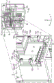
FIG. 4 is a partial perspective view depicting the configuration of the periphery of the forming station.
Fig. 5 is a flowchart showing an example of a control method of the molding system executed by the controller.
Fig. 6 shows details of the chuck.
Fig. 7 is an illustrative view of a chuck plate of another exemplary embodiment.
Throughout the drawings, the same reference numerals and symbols are used to designate the same features, elements, components or portions of the illustrated embodiments, unless otherwise specified. Further, while the present disclosure will now be described in detail with reference to the drawings, this is done in connection with the illustrative exemplary embodiments. It is intended that changes and modifications may be made to the described exemplary embodiments without departing from the true scope and spirit of the present disclosure, as defined by the following claims.
Detailed Description
The present disclosure has several embodiments, and relies on patents, patent applications, and other references for details known to those skilled in the art. Thus, when a patent, patent application, or other reference is cited or repeated herein, it is understood that it is incorporated by reference in its entirety for all purposes and for the purposes of the stated claims.
Referring to the drawings, arrow symbols X and Y in the respective drawings indicate horizontal directions orthogonal to each other, and arrow symbol Z indicates a vertical (standing) direction with respect to the ground.
Fig. 1-4 show an injection molding system 1 of US 2018/0009146/japanese patent publication No.2018-001738/VN20160002505, which is used herein for information/description purposes only.
The injection molding system 1 includes an injection molding machine 2, conveyors 3A and 3B, and a control device 4. The injection molding system 1 manufactures molded articles while alternating a plurality of molds using conveyors 3A and 3B for one injection molding machine 2. Two molds 100A and 100B are used.
The mold 100A/100B is a pair of a fixed mold 101 and a movable mold 102 that opens/closes with respect to the fixed mold 101. The molded article is molded by injecting a molten resin into a cavity formed between the fixed mold 101 and the movable mold 102. The clamping plates 101a and 102a are fixed to the fixed mold 101 and the movable mold 102, respectively. The clamping plates 101a and 102a are used to lock the mold 100A/100B to the molding operation position 11 (mold clamping position) of the injection molding machine.
For the mold 100A/100B, a self-closing unit 103 is provided for maintaining a closed state between the fixed mold 101 and the movable mold 102. The self-closing unit 103 can prevent the mold 100A/100B from being opened after unloading the mold 100A/100B from the injection molding machine 2. The self-closing unit 103 holds the mold 100A/100B in a closed state using a magnetic force. The self-closing units 103 are located at a plurality of positions along the opposing surfaces of the fixed mold 101 and the movable mold 102. The self-closing unit 103 is a combination of an element on the fixed mold 101 side and an element on the movable mold 102 side. For the self-closing unit 103, two or more pairs are generally installed for one of the molds 100A and 100B.
The conveyor 3A loads/unloads the mold 100A onto/from the molding operation position 11 of the injection molding machine 2. The conveyor 3B loads/unloads the mold 100B onto/from the molding operation position 11. The conveyor 3A, the injection molding machine 2, and the conveyor 3B are arranged in this order in the X-axis direction. In other words, the conveyor 3A and the conveyor 3B are arranged laterally with respect to the injection molding machine 2 to sandwich the injection molding machine 2 in the X-axis direction. The conveyors 3A and 3B are arranged to face each other, and the conveyor 3A is arranged on one lateral side of the injection molding machine 2, while the conveyor 3B is arranged on the other lateral side. The forming operation position 11 is located between the conveyor 3A and the conveyor 3B. The conveyors 3A and 3B respectively include a frame 30, a conveying unit 31, a plurality of rollers 32, and a plurality of rollers 33.
The frame 30 is a main frame of the conveyors 3A and 3B, and supports a conveying unit 31 and a plurality of rollers 32 and 33. The conveying unit 31 is a device that moves the mold 100A/100B back and forth in the X-axis direction and removes and inserts the mold 100A/100B with respect to the molding operation position 11.
The conveying unit 31 is an electric cylinder having a motor as a driving source, and includes a rod that moves forward/backward with respect to the cylinder. The cylinder is fixed to the frame 30, and the fixed die 101 is fixed to the edge portion of the rod. For the transfer unit 31, both a fluid actuator and an electric actuator may be used, wherein the electric actuator may provide better control accuracy of the position or velocity when transferring the mold 100A/100B. The fluid actuator may be, for example, an oil hydraulic cylinder or an air cylinder. In addition to the electric cylinder, the electric actuator may be a rack and pinion mechanism having a motor as a drive source, a ball screw mechanism having a motor as a drive source, or the like.
A conveying unit 31 is independently arranged for each of the conveyors 3A and 3B. However, a common support member that supports the molds 100A and 100B may be used, and a single common conveying unit 31 may be arranged for the support member. The case where the conveying unit 31 is independently arranged for each of the conveyors 3A and 3B can cope with the case where the moving stroke differs between the mold 100A and the mold 100B at the time of conveyance. For example, there is a case where the molds cannot be simultaneously conveyed due to a difference in width of the molds (width in the X direction) or a difference in thickness of the molds (width in the Y direction).
The plurality of rollers 32 constitute one row of rollers arranged in the X-axis direction, wherein two rows are configured to be separated in the Y-axis direction. The plurality of rollers 32 rotate about the rotation axis in the Z-axis direction, and guide the movement of the mold 100A/100B in the X-axis direction, contact the side surfaces of the mold 100A/100B (the side surfaces of the clamping plates 101a and 102 a), and support the mold 100A/100B from the sides. The plurality of rollers 33 constitute one row of rollers arranged in the X-axis direction, wherein two rows are configured to be separated in the Y-axis direction. The plurality of rollers 33 rotate about the rotation axis in the Y direction and smooth the movement of the mold 100A/100B in the X direction, support the bottom surface of the mold 100A/100B (the bottom surface of the clamping plates 101a and 102 a), and support the mold 100A/100B from below.
The control device 4 includes a controller 41 for controlling the injection molding machine 2, a controller 42A for controlling the conveyor 3A, and a controller 42B for controlling the conveyor 3B. Each of the controllers 41, 42A, and 42B includes a processor such as a CPU, a RAM, a ROM, a storage device such as a hard disk, and an interface (not shown) connected to a sensor or an actuator. The processor executes programs stored in the storage device. An example of a program (control) executed by the controller 41 is described below. The controller 41 is communicatively connected with the controllers 42A and 42B, and provides instructions to the controllers 42A and 42B related to the conveyance of the molds 100A/100B. If the loading and unloading of the mold 100A/100B is terminated, the controllers 42A and 42B send a signal for operation completion to the controller 41. In addition, the controllers 42A and 42B transmit an emergency stop signal to the controller 41 when an abnormality occurs.
A controller is arranged for each of the injection molding machine 2, the conveyor 3A, and the conveyor 3B, but one controller may control all three machines. The conveyors 3A and 3B may be controlled by a single controller for more reliable and coordinated operation.
Fig. 2 shows a side view of the injection molding machine 2. Fig. 3 shows an end view of the fixed platen 61, which is a view viewed from the direction of the arrow along the line I-I in fig. 2. Fig. 4 shows a partial perspective view for describing the configuration of the periphery of the molding operation position 11.
Referring to fig. 1 and 2, the injection molding machine 2 includes an injection device 5, a clamp device 6, and a take-out robot 7 for discharging molded articles. The injection device 5 and the clamping device 6 are arranged on the frame 10 in the Y-axis direction.
The injection device 5 includes an injection cylinder 51 arranged to extend in the Y-axis direction. The injection cylinder 51 includes a heating device (not shown) such as a band heater, and melts the resin introduced from the hopper 53. The screw 51a is integrated into the injection cylinder 51, and the resin introduced into the injection cylinder 51 is plasticized and measured by the rotation of the screw 51a, and the molten resin can be injected from the injection nozzle 52 by the movement of the screw 51a in the axial direction (Y-axis direction).
In fig. 2, an example of a shutoff nozzle is shown as the nozzle 52. With the opening/closing mechanism 56 of fig. 2, a pin 56a for opening/closing the discharge port 52a is arranged. The pin 56a is connected to an actuator (cylinder) 56c via a link 56b, and opens and closes the discharge port 52a by operation of the actuator 56 c.
The injection cylinder 51 is supported by a drive unit 54. In the drive unit 54, a motor for plasticizing and measuring the resin by rotating the drive screw 51a and a motor for driving the drive screw 51a to move forward/backward in the axial direction are arranged. The driving unit 54 can move forward/backward in the Y-axis direction along the rails 12 on the frame 10, and an actuator (e.g., an electric cylinder) 55 for moving the injection device 5 forward/backward in the Y-axis direction is disposed in the driving unit 54.
The clamping device 6 performs clamping, opening, and closing of the mold 100A/100B. In the clamping device 6, there are arranged in order in the Y-axis direction: a fixed platen 61, a movable platen 62, and a movable platen 63. A plurality of tie rods 64 pass through the platens 61-63. Each tie bar 64 is a shaft extending in the Y-axis direction, and one end thereof is fixed to the fixed platen 61. Each tie rod 64 is inserted into a corresponding through hole formed in the movable platen 62. The other end of each tie rod 64 is fixed to the movable platen 63 by an adjusting mechanism 67. The movable platens 62, 63 are movable in the Y-axis direction along the rails 13 on the frame 10, while the fixed platen 61 is fixed to the frame 10.
The toggle mechanism 65 is disposed between the movable platen 62 and the movable platen 63. The toggle mechanism 65 moves the movable platen 62 forward/backward in the Y-axis direction with respect to the movable platen 63 (in other words, with respect to the fixed platen 61). The toggle mechanism 65 includes links 65a to 65 c. The link 65a is rotatably connected to the movable platen 62. The link 65b is pivotably connected to the movable platen 63. The link 65a and the link 65b are pivotably connected to each other. The link 65c and the link 65b are pivotably connected to each other. Link 65c is pivotally connected to arm 66 c.
The arm 66c is fixed to the ball nut 66 b. The ball nut 66b is engaged with a ball screw shaft 66a extending in the Y-axis direction, and is moved forward/backward in the Y-axis direction by rotation of the ball screw shaft 66 a. The ball screw shaft 66a is rotatably supported by the movable platen 63, and the motor 66 is supported by the movable platen 63. The motor 66 rotationally drives the ball screw shaft 66a while detecting the rotation amount of the motor 66. The driving motor 66 can clamp, open, and close the mold 100A/100B while detecting the amount of rotation of the motor 66.
The injection molding machine 2 includes sensors 68 for measuring the clamping force, wherein each sensor 68 is, for example, a strain gauge provided on the tie bar 64, and calculates the clamping force by detecting deformation of the tie bar 64.
The adjustment mechanism 67 includes a nut 67b supported on the movable platen 63 so as to be rotatable, a motor 67a as a drive source, and a transmission mechanism for transmitting a driving force of the motor 67a to the nut 67 b. Each tie rod 64 passes through a hole formed in the movable platen 63 and engages with a nut 67 b. By rotating the nut 67b, the engagement position in the Y-axis direction between the nut 67b and the tie bar 64 is changed. That is, the position at which the movable platen 63 is fixed with respect to the tie bars 64 changes. This makes it possible to change the space between the movable platen 63 and the fixed platen 61, and to adjust the clamping force and the like.
The molding operation position 11 is a region between the fixed platen 61 and the movable platen 62.
The mold 100A/100B introduced into the molding operation position 11 is sandwiched between the fixed platen 61 and the movable platen 62 so as to be clamped. Opening and closing based on the movement of the movable mold 102 is performed by the movement of the movable platen 62.
Fig. 3 shows an opening portion 61a in a central portion of the fixed platen 61 through which the nozzle 52 moves forward/backward. The plurality of rollers BR are supported to a surface (referred to as an inner surface) of the fixed platen 61 on the movable platen 62 side so that they can freely rotate. The plurality of rollers BR rotate about the rotation axis in the Y-axis direction and smooth the movement of the mold 100A/100B in the X-axis direction, support the bottom surface of the mold 100A/100B (the bottom surface of the clamping plate 101 a), and support the mold 100A/100B from below. Roller supports 620 are fixed to both sides of the fixed platen 61 in the X-axis direction, and a plurality of rollers BR are supported by the roller supports 620.
A groove 61b extending in the X-axis direction is formed on the inner surface of the fixed platen 61.
The grooves 61b are formed in two vertically separated rows. A roller unit 640 is provided on each groove 61 b. For the roller unit 640, the plurality of rollers SR are supported such that they freely rotate. The plurality of rollers SR rotate about the rotation axis in the Z-axis direction, and guide the movement of the mold 100A/100B in the X-axis direction, contact the outer surface of the mold 100A/100B (the outer surface of the clamping plate 101 a), and support the mold 100A/100B from the side. As shown in the sectional view of the line I I-I I, although the roller unit 640 is positioned at a position where the roller SR protrudes from the groove 61b by the bias of the spring 641, it retracts into the groove 61b at the time of nipping, and is positioned at a position where the roller SR does not protrude from the groove 61 b. The roller unit 640 may prevent the molds 100A/100B and the inner surface of the fixed platen 61 from contacting and damaging the inner surface when the molds 100A/100B are alternated, and the roller unit 640 may not obstruct the closing of the inner surface of the fixed platen 61 and the molds 100A/100B when clamped.
Roller supports 630 are fixed to both sides of the fixed platen 61 in the X-axis direction, and a plurality of rollers SR are supported by the roller supports 630.
A plurality of fixing mechanisms (clamps) 610 for fixing the fixed mold 101 to the fixed platen 61 are arranged on the fixed platen 61. Each fixing mechanism 610 includes an engaging portion 610a that engages with the clamp plate 101a, and a built-in actuator (not shown) that moves the engaging portion 610a between an engaging position and an engagement releasing position.
Note that, with the movable platen 62, similarly to the fixed platen 61, a plurality of rollers BR, roller supports 620 and 630, a roller unit 640, and a fixing mechanism 610 for fixing the movable mold 102 are arranged.
As shown in fig. 4, the periphery of the clamping device 6 is surrounded by a cover (outer cover plate) 60 for safety, but in order to alternate the molds 100A/100B, an opening 60A through which the mold 100A/100B passes is formed at the side of the molding operation position 11. Each opening 60A is generally continuously open, enabling free removal and insertion of the mold 100A/100B from and into the molding operation position 11.
Returning to fig. 2, the take-out robot 7 will now be described. The picking robot 7 includes a rail 71 extending in the X-axis direction and a movable rail 72 movable on the rail 71 in the X-axis direction. The movable rail 72 is arranged to extend in the Y-axis direction, and a slider 73 is arranged on the movable rail 72. The slider 73 is guided by the movable rail 72 to move in the Y-axis direction, and moves the elevating shaft 73a up and down in the Z-axis direction. A vacuum head 74 is disposed at a lower end of the elevating shaft 73a, and a chuck plate 75 dedicated to molded articles is mounted on the vacuum head 74.
After opening, the take-out robot 7 moves the vacuum head 74 between the fixed mold 101 and the movable mold 102 via the rail 71, the movable rail 72, and the slider 73, as shown by the broken line in fig. 2, sticks to the molded article, and delivers it to the outside of the mold 100A/100B.
Fig. 6 is provided herein for information/description purposes only. EX1 of fig. 6 represents an example of the chuck plate 75. The chuck plate 75 includes a holding portion 75A and a holding portion 75B. The vacuum head 74 rotates the chuck plate 75 about the axis 74a, and displaces the chuck plate 75 so that the positions of the holding portion 75A and the holding portion 75B are changed. This makes it possible to switch the holding portion facing the molded article, thereby handling different molded articles in a short time without replacing the chuck plate 75. EX2 of fig. 6 shows another example of the chuck plate 75. The chuck plate 75 includes a holding portion 75A and a holding portion 75B. The vacuum head 74 includes a rail 74b and a slider 74c moving along the rail 74b, and a chuck plate 75 is disposed on the slider 74 c. Moving the slider 74c causes the chuck plate 75 to be displaced to change the positions of the holding portion 75A and the holding portion 75B. This makes it possible to switch the holding portion facing the molded article, thereby handling different molded articles in a short time without replacing the chuck plate 75.
Fig. 5 is a flowchart showing an example of the control method of the injection molding system 1 executed by the controller 41.
In the following example, a case is envisaged in which the molding operation is performed while alternating the molds 100A and 100B in the following manner: molding using the mold 100A → molding using the mold 100B → molding using the mold 100A, and the like. However, when the mold 100B is opened, the molded article a molded in the mold 100A is placed in the mold 100B. Then, a resin is injected into the mold 100B including the mold a, and the mold B integrated with the mold a is manufactured.
At the start of this process flow, the mold 100B injected with resin has been unloaded from the injection molding machine 2 to the conveyor 3B. The procedure after this step is described below. In step S1 of fig. 5, the cooled mold 100A is loaded into the injection molding machine 2. The mold a includes a molded article a made of resin injected in a previous cycle and then hardened in a cooling process. In step S2, the motor 66 is driven to move the movable platen 62 away from the fixed platen 61. The fixed mold 101 is fixed to the fixed platen 61 by the fixing mechanism 610, and the movable mold 102 is fixed to the movable platen 62 by the fixing mechanism 610. Accordingly, the movable mold 102 is separated from the fixed mold 101, and the mold 100A is opened.
In step S3, the takeout robot 7 drives the holding portion 75A to remove the molded article a left on the movable mold 102 side of the mold 100A. The removed molded article a continues to be held by the holding portion 75A until the process of step S12.
In step S4, the clamping device 6 drives the motor 66 to drive the toggle mechanism 65 to perform clamping of the mold 100A with the fixed platen 61 and the movable platen 62.
In step S5, preparation for injection into the mold 100A is performed by the injector 5. Injector 5 drives actuator 55 to move injector 5 to move nozzle 52 into contact with mold 100A.
In step S6, injection of the molten resin and pressure holding are performed. The injector 5 is driven to fill the molten resin from the nozzle 52 into the cavity in the mold 100A and to press the resin into the mold 100A at high pressure to compensate for the volume reduction due to the solidification of the resin. During the process of step S6, the actual clamping force is measured by the sensor 68. During molding, since the temperature of the mold 100A gradually increases, the mold 100A thermally expands. There are cases where a difference occurs between the initial clamping force and the clamping force after a lapse of time. Therefore, the clamping force at the next clamping can be corrected based on the measurement result of the sensor 68.
The clamping force is adjusted by adjusting the position of the movable platen 63 relative to the tie bars 64 by driving the motor 67. This makes it possible to improve the accuracy of the clamping force by adjusting the clamping force by correcting the initial value of the position of the movable platen 63 relative to the tie bars 64 based on the measurement result of the sensor 68. The adjustment of the position of the movable platen 63 with respect to the tie bars 64 may be performed at any timing (e.g., step S6, step S7, steps S13-S15 in the flowchart of fig. 5).
In step S7, processing related to the clamping device 6 is executed. First, the lock of the mold 100A by the fixing mechanism 610 is released. The motor 66 is driven to drive the toggle mechanism 65. This results in the removal of the clamping force, and the movable platen 62 is slightly separated relative to the fixed platen 61, creating a space where the molds 100A and 100B can be alternated.
In step S8, the mold 100A is unloaded or ejected from the molding operation position 11 to the conveyor 3A. After the mold 100A is ejected from the molding operation position 11, the mold 100A is cooled to an appropriate temperature for a predetermined period of time. The mould typically comprises a channel extending inside the mould, and when preparing the mould for injection moulding, the temperature controller is connected via a hose to the interface of the channel formed on the surface of the mould. Fluid at a certain temperature flows into the interior of the mold from the temperature controller to maintain the mold at a certain temperature. In the injection molding process including the cooling process, the fluid generally always flows inside the mold.
Generally, after step S8, the mold 100A is still heated by the molten resin injected into the mold 100A. In the cooling process by the fluid from the temperature controller, the temperature is lowered to a predetermined temperature, for example, 60 degrees celsius. The cooling process continues until a predetermined period of time has elapsed from the start of the cooling process.
In some injection molding processes, such as thermoforming and cold forming, the cooling process includes a dedicated temperature controller to cool the mold to a temperature that is different from the temperature at which the mold receives molten resin from the injection machine.
In step S9, the mold 100B is loaded from the conveyor 3B to the molding operation position 11. In step S10, the movable platen 62 is separated from the fixed platen 61 by driving the motor 66. The fixed mold 101 is fixed to the fixed platen 61 by the fixing mechanism 610, and the movable mold 102 is fixed to the movable platen 62 by the fixing mechanism 610. Therefore, the movable mold 102 is separated from the fixed mold 101, and the mold 100B is opened against the force of the self-closing unit 103. In step S11, the molded article B joined to the molded article a and left on the movable mold 102 side of the mold 100B is taken out by driving the take-out robot 7 and conveyed outside the injection molding machine 2 using the holding portion 75B.
In step S12, the molded article a held by the holding portion 75A is placed in the metal mold B. In step S13, clamping of the mold 100B is performed. In step S14, injection into the mold 100B is prepared by driving the actuator 55 to move the injector 5. This causes nozzle 52 to contact mold 100B.
In step S15, injection of the molten resin and pressure holding are performed. In step S16, the processing related to the chucking device 6 is executed, which is the same as the process in step S7. In step S17, the mold 100B is unloaded from the molding operation position 11 to the conveyor 3B.
As described above, in the present embodiment, the cooling of the mold 100A/100B is performed on the conveyor 3A or 3B outside the injection molding machine 2. Further, during cooling of one of the molds 100A or 100B, each of the processes of mold ejection → clamping → injection/pressure holding is performed on the other of the molds 100A or 100B by the injection molding machine 2. Since the opening and the molded article ejection are performed by the injection molding machine 2, the conveyors 3A and 3B need not include a function for opening and a function for molded article ejection.
Therefore, it is possible to manufacture the molded article B combined with the molded article a while alternating the plurality of molds 100A and 100B by one injection molding machine 2, while avoiding an increase in the cost of the injection molding system 1. Since the injection molding system 2 molds the molded article B after the molding of the molded article a, it is not necessary to manufacture a large number of molded articles a in advance. Thus, the risk of storing an excess stock of molded articles a can be reduced.
Fig. 7 is an illustrative view of a chuck plate of another exemplary embodiment. Fig. 7 shows a chuck plate 74e attached to the end of a shaft 74 d. The chuck plate 74e includes a plurality of holding portions 75A on one surface and a plurality of holding portions 75B on the other surface. The holding portion facing the molded article can be switched by rotating the chuck plate 74e about the shaft 74 d. The rotation angle is not limited to 180 degrees. Any angle that enables the retaining portion to properly capture and retain the molded article is suitable.
The take-out robot 7 may include a robot hand that can hold both the molded article a and the molded article B. In the above embodiment, after the takeout robot 7 has taken out the molded article from the first mold, the takeout robot 7 holds the molded article until the takeout robot 7 places the molded article in the second mold. In another exemplary embodiment, the take-out robot 7 may place the molded article on a table (not shown) temporarily disposed near the molding operation position 11.
If it is desired to sufficiently cool the article a prior to placing the article a in the mold 100B, the article a may be cooled on the table while one or more cycles of switching the molds are in progress. In this case, it is preferable to place the molded articles A on the table for a period longer than the number of cycles required to cool them. This enables the molded article a molded in one or more previous replacement cycles to be used as the molded article to be placed in the mold 100B.
A sensor (not shown) may be installed in the mold to be able to detect that the molded article a is placed in the mold 100B. Pressure sensors or optical sensors may be used. A camera installed near the molding operation position 11 may be used to capture an image of the placement, where the captured image is used to determine the placement. The sensor for detecting that the molded article a is placed in the mold 100B may be located in other positions in the injection molding machine 2 than the mold 100A/100B and the take-out robot 7.
In another exemplary embodiment, a table may be provided to adjust the holding orientation of the molded article a held by the takeout robot 7. The repositioning of the article a may also take place on the table. A sensor (image sensor, etc.) (not shown) is mounted near the table or on the take-out robot 7 to enable a precise orientation for placing the molded article in the mold 100B instead of holding.
In the exemplary embodiment of the injection molding system 1, an inspection process is performed to ensure that the molded part is deemed acceptable. For example, if no abnormality or the like is detected on the surface of the mold or within the internal structure of the mold, the molded article is considered to be acceptable.
The inspection process may include, for example, an image capture device located in the injection molding machine 2 that captures an image of the appearance of the molded article. The molded part is inspected for its surface condition and shape based on the captured images. The molded part may also be inspected for its color based on the captured image.
An image capture device that captures the internal structure of the molded part using radiation (e.g., X-rays) may also be used for the inspection process. In the case where the inspection process of the molded article B is performed outside the injection molding machine 2, the inspection process of the molded article a performed inside the injection molding machine 2 may be only the appearance inspection.
In the inspection step, the mold a is taken out by the take-out robot 7, and one or more image taking devices controlled by the control device 4 take an image with the appearance of the mold a in a state where the mold a is held by the take-out robot 7. The captured image is analyzed by the control device 4 and a result indicating whether the molded article a is a qualified component is provided. In another embodiment, the captured image may be analyzed by a component other than the control device 4.
In another embodiment, the molded article a taken out by the take-out robot 7 may be placed at a predetermined position outside the injection molding machine 2, and an inspection process for the molded article a may be performed at the predetermined position. In this case, the takeout robot 7 does not hold the molded article a during the period from when the takeout robot 7 removes the molded article a from the mold 100A to when the takeout robot 7 places the molded article a in the mold 100B.
In the case where the molded article a is considered to be defective, there are various options that can be followed. In one option, the mold 100A is not moved from the molding operation position 11 in the injection molding machine 2, and injection molding using the mold 100A is repeated. In the case where the mold 100A has been moved from the injection molding machine 2 before the inspection process is performed, the mold 100A is moved again to the injection molding machine 2, and injection molding using the mold 100A is repeated. The moulding a is then checked again. If the molded article a is judged to be a qualified part, the molded article a is placed in the mold 100B. If the molded article a is judged to be a qualified part, the mold 100A is moved from the injection molding machine 2, and the mold 100B is moved in the injection molding machine 2 as usual.
In the second option, another conforming part is prepared in advance outside the injection molding machine 2 while the prepared molded article a is held by the take-out robot 7, and the conforming part is used instead of the nonconforming part. In this case, based on the determination that the mold a is a defective part, the control device 4 controls the take-out robot 7 to release the defective part so that the defective part can be handled. The prepared molded article a is held by the take-out robot 7 and placed in the mold 100B. If the molded article a is judged to be a qualified part, the molded article a that has just been removed from the mold 100A by the take-out robot 7 is placed in the mold 100B as usual.
In a third option, the take-out robot 7 places the molded article a at a predetermined position outside the injection molding machine 2. In this case, after the molded article a is placed at the predetermined position, the take-out robot 7 holds another molded article a judged as a qualified component and places it in the mold 100B. This procedure is effective in the case where the time required to inspect the molded article a is relatively long.
The processing associated with the various options described above is preinstalled in the control device 4. The injection molding machine 2 selects one of the processes, for example, according to an input of a user.
In the case where the molded article a is not a qualified part, the molded article B including the molded article a is not a qualified part. Before the molded article a is placed in the mold 100B, the molded article a should be inspected to determine whether it is a qualified part.
In the second option described above, it is preferred to produce only some of the moldings a beforehand. That is, the mold 100A is placed at the molding operation position 11, and injection molding is performed until a predetermined number (e.g., 10) of conforming parts a are produced. The injection molding machine 2 operates in a mode in which injection molding uses only the mold 100A. In the case where a predetermined number of acceptable parts a are produced, the injection molding machine 2 enters a mode in which the mold 100A and the mold 100B are alternately used for injection molding. In the third option, a mode in which only the mold 100A is used for injection molding may be employed.
In the injection molding process after the molded article a is judged to be a defective part in the above-described first option, and in the injection molding process for producing a predetermined number of molded articles a in advance, there is no need to cool the mold 100A at a position other than the molding operation position 11. In other words, there is no need to cool the mold 100A by moving the mold 100A out of the injection molding machine 2. However, there is a difference between the pressure applied to the mold in the case where the mold is cooled on the conveyor 3A or 3B and the pressure applied to the mold in the case where the mold is cooled at the molding operation position 11 in the injection molding machine 2. Thus, the quality of the mold may be different in the two cases.
In the above-described injection molding process, the mold 100A may be cooled while moving the mold 100A from the molding operation position 11. The mold 100A may also be cooled with the mold 100A in the molding operation position 11, and the platens 61, 62 may be separated from the mold 100A. This makes the pressure applied to the mold 100A similar to the pressure applied to the mold 100A in the case where the mold 100A is cooled on the conveyor 3A or 3B.
According to one embodiment, a plurality of take-out robots 7 may be installed. For example, a robot a (not shown) is used to remove the molded article a from the mold 100A and place the molded article a in the mold 100B. A robot B (not shown) may be used to remove the molded article B from the mold 100B. In this case, since the robot a only needs to be able to operate near the molding operation position 11, it may be installed, for example, below near the molding operation position 11, and may have an operation area smaller than that of the robot B. In such a configuration, the size of the robot B may need to be able to transfer the removed molded article B outside the injection molding machine 2.
Although the above-described embodiment refers to the use of two molds, the number of molds is not limited to two. The above-described embodiments enable alternation between a plurality of molds while injection molding is performed.
Although the above embodiment has described that the clamping, the injection/pressure holding, the opening, and the ejection are performed with the mold in the molding operation position 11, this is not to be considered as limiting. It is not necessary to perform all of the processes at the forming station 11. Some of the processes may be performed at a different location than the forming operation location 11. For example, after the cooling process of the mold, the mold is conveyed to a predetermined position in the injection molding machine 2, which is different from the molding operation position 11. The molded article may be removed at the predetermined location. Then, the mold can be conveyed from the predetermined position to the molding operation position 11.
Although the above embodiment discusses the cooling process being performed with the mold on the conveyor 3A or 3B and outside the injection molding machine 2, this is not to be considered as limiting. The cooling process may be performed at a position where the mold does not contact the fixed platen 61 and the movable platen 62. For example, the cooling process may be performed with a portion of the mold located inside the injection molding machine 2 and another portion of the mold located outside the injection molding machine 2. In the case of a configuration in which a part of the conveyor 3A or 3B is located inside the injection molding machine 2, the cooling process may be performed with a part of the mold located inside the injection molding machine 2 and another part of the mold located on the conveyor 3A or 3B.
Definition of
In referring to the description, specific details are set forth in order to provide a thorough understanding of the disclosed examples. In other instances, well known methods, procedures, components, and circuits have not been described in detail as not to unnecessarily obscure aspects of the present disclosure.
It will be understood that if an element or component is referred to herein as being "on," "against," "connected to," or "coupled to" another element or component, it can be directly on, against, connected to, or coupled to the other element or component, or intervening elements or components may be present. In contrast, if an element is referred to as being "directly on," "directly connected to" or "directly coupled to" another element or component, there are no intervening elements or components present. Where used, the term "and/or," if so provided, includes any and all combinations of one or more of the associated listed items.
Spatially relative terms such as "below … …," "below … …," "below … …," "below," "above … …," "above," "proximal," "distal" may be used herein for convenience in describing the relationship of one element or feature to another element or feature illustrated in the various drawings. It will be understood that the spatially relative terms are intended to encompass different orientations of the device in use or operation in addition to the orientation depicted in the figures. For example, when the device in the figures is turned over, elements described as "below" or "beneath" other elements or features would then be oriented "above" the other elements or features. Thus, relative spatial terms such as "above. The device may assume other orientations (rotated 90 degrees or at other orientations) and the spatially relative descriptors used herein interpreted accordingly. Similarly, the relative spatial terms "proximal" and "distal" may also be interchangeable, where applicable.
The term "about" as used herein means, for example, within 10%, within 5%, or less. In some embodiments, the term "about" may mean within measurement error.
The terms first, second, third, etc. may be used herein to describe various elements, components, regions, components and/or sections. It will be understood that these elements, components, regions, components and/or sections should not be limited by these terms. These terms are only used to distinguish one element, component, region, component or section from another region, component or section. Thus, a first element, component, region, component, or section discussed below could be termed a second element, component, region, component, or section without departing from the teachings herein.
The terminology used herein is for the purpose of describing particular embodiments only and is not intended to be limiting. The use of the terms "a" and "an" and "the" and similar referents in the context of describing the disclosure (especially in the context of the following claims) are to be construed to cover both the singular and the plural, unless otherwise indicated herein or clearly contradicted by context. The terms "comprising," "having," "including," and "containing" are to be construed as open-ended terms (i.e., meaning "including, but not limited to,") unless otherwise noted. In particular, the terms "comprises" and/or "comprising," when used in this specification, specify the presence of stated features, integers, steps, operations, elements, and/or components, but do not preclude the presence or addition of one or more other features, integers, steps, operations, elements, components, and/or groups thereof not expressly stated. Recitation of ranges of values herein are merely intended to serve as a shorthand method of referring individually to each separate value falling within the range, unless otherwise indicated herein, and each separate value is incorporated into the specification as if it were individually recited herein. For example, if a range of 10-15 is disclosed, then 11, 12, 13, and 14 are also disclosed. All methods described herein can be performed in any suitable order unless otherwise indicated herein or otherwise clearly contradicted by context. The use of any and all examples, or exemplary language (e.g., "such as") provided herein, is intended merely to better illuminate the disclosure and does not pose a limitation on the scope of the disclosure unless otherwise claimed. No language in the specification should be construed as indicating any non-claimed element as essential to the practice of the disclosure.
It is understood that the methods and compositions of the present disclosure may be combined in the form of various embodiments, only some of which are disclosed herein. Variations of those embodiments may become apparent to those of ordinary skill in the art upon reading the foregoing description. The inventors expect skilled artisans to employ such variations as appropriate, and the inventors intend for the disclosure to be practiced otherwise than as specifically described herein. Accordingly, this disclosure includes all modifications and equivalents of the subject matter recited in the claims appended hereto as permitted by applicable law. Moreover, any combination of the above-described elements in all possible variations thereof is encompassed by the disclosure unless otherwise indicated herein or otherwise clearly contradicted by context.
Combinations of any of the exemplary embodiments disclosed above are also included as embodiments of the present disclosure. While the above exemplary embodiments discuss illustrative embodiments, these embodiments are not to be considered as limiting.
Claims (13)
Applications Claiming Priority (3)
| Application Number | Priority Date | Filing Date | Title |
|---|---|---|---|
| US201962849482P | 2019-05-17 | 2019-05-17 | |
| US62/849,482 | 2019-05-17 | ||
| PCT/US2020/032728 WO2020236488A1 (en) | 2019-05-17 | 2020-05-13 | Manufacturing method and injection molding system |
Publications (2)
| Publication Number | Publication Date |
|---|---|
| CN113840709A true CN113840709A (en) | 2021-12-24 |
| CN113840709B CN113840709B (en) | 2023-10-10 |
Family
ID=73458254
Family Applications (1)
| Application Number | Title | Priority Date | Filing Date |
|---|---|---|---|
| CN202080036272.0A Active CN113840709B (en) | 2019-05-17 | 2020-05-13 | Manufacturing methods and injection molding systems |
Country Status (5)
| Country | Link |
|---|---|
| US (1) | US20220212385A1 (en) |
| EP (1) | EP3969248A4 (en) |
| JP (1) | JP2022533977A (en) |
| CN (1) | CN113840709B (en) |
| WO (1) | WO2020236488A1 (en) |
Families Citing this family (2)
| Publication number | Priority date | Publication date | Assignee | Title |
|---|---|---|---|---|
| WO2022256441A1 (en) * | 2021-06-02 | 2022-12-08 | Canon Virginia, Inc. | Manufacturing method using shuttle mold and overmolding |
| CN119305122B (en) * | 2024-11-29 | 2025-10-31 | 江西远翔塑胶有限公司 | An automatic nut insertion system |
Citations (19)
| Publication number | Priority date | Publication date | Assignee | Title |
|---|---|---|---|---|
| US4540359A (en) * | 1981-10-08 | 1985-09-10 | Nissei Plastics Industrial Co., Ltd. | Injection molding machine |
| US5112558A (en) * | 1988-01-29 | 1992-05-12 | Husky Injection Molding Systems Ltd. | Injection molding process |
| US6086808A (en) * | 1997-08-19 | 2000-07-11 | Universal Ventures | Repositioning of articles between different positions within an intermittently accessible space |
| US6626659B1 (en) * | 1999-07-09 | 2003-09-30 | Libbey-Owens-Ford Co. | Injection molding method and apparatus having improved detachable clamping unit with horizontal booking dies |
| WO2006077127A1 (en) * | 2005-01-22 | 2006-07-27 | Zahoransky Gmbh Formen- Und Werkzeugbau | Injection molding machine with a pair of molding inserts that can be removed from a holding device |
| US20070057392A1 (en) * | 2003-10-06 | 2007-03-15 | Hideki Yoshida | Injection molding machine and injection molding method |
| JP2009214438A (en) * | 2008-03-11 | 2009-09-24 | Seiko Epson Corp | Injection moulding apparatus and method for molding injection-molded article |
| CN102233642A (en) * | 2010-03-23 | 2011-11-09 | 佳能株式会社 | Plastics molding system and optical element formed by the same |
| CN102264520A (en) * | 2008-10-23 | 2011-11-30 | Lrm工业国际公司 | Method of forming a molded article by wireless control |
| CN103826824A (en) * | 2011-07-27 | 2014-05-28 | 弗莱克斯电子有限责任公司 | Temperature controlled molding of composite components |
| DE102013004408A1 (en) * | 2013-03-01 | 2014-09-04 | Otto Männer Innovation GmbH | Injection molding and cooling device for forming and cooling plastic bottle, has linear drive mechanism inducing neck ring plates from first position to second position, and plunger driving cube structure between positions |
| US20140332991A1 (en) * | 2013-04-02 | 2014-11-13 | Engel Austria Gmbh | Method and device for the production of an injection-moulded part |
| CN104441474A (en) * | 2013-09-19 | 2015-03-25 | 佳能株式会社 | Injection molding apparatus, injection molding method, and molded product manufacturing method |
| US20150298376A1 (en) * | 2014-04-17 | 2015-10-22 | Nissei Plastic Industrial Co., Ltd. | Mold attaching method to mold clamping device |
| WO2015186246A1 (en) * | 2014-06-06 | 2015-12-10 | 三菱重工プラスチックテクノロジー株式会社 | Injection molding method and injection molding machine |
| US20170305084A1 (en) * | 2014-09-11 | 2017-10-26 | Toshiba Kikai Kabushiki Kaisha | Apparatus and method for producing light diffusing lens |
| CN107584725A (en) * | 2016-07-07 | 2018-01-16 | 佳能越南有限责任公司 | Manufacturing method and injection molding system |
| CN109109265A (en) * | 2018-08-28 | 2019-01-01 | 优力精密塑胶(苏州)有限公司 | One kind vacuumizing auxiliary double-shot moulding device |
| US20200230856A1 (en) * | 2017-10-17 | 2020-07-23 | Toshiba Kikai Kabushiki Kaisha | Injection molding machine |
Family Cites Families (8)
| Publication number | Priority date | Publication date | Assignee | Title |
|---|---|---|---|---|
| JPH07119012B2 (en) | 1988-03-31 | 1995-12-20 | バンドー化学株式会社 | Injection molding machine |
| JPH0681696B2 (en) * | 1989-06-09 | 1994-10-19 | 日精樹脂工業株式会社 | Composite injection molding machine and composite injection molding method |
| US5753280A (en) * | 1996-06-28 | 1998-05-19 | Husky Injection Molding Systems Ltd. | Compact and torque free side entry trolley robot |
| JPH10180797A (en) | 1996-12-26 | 1998-07-07 | Canon Inc | Molding method and molding apparatus for insert molded products |
| DE10029154B4 (en) * | 2000-06-19 | 2005-05-12 | Hekuma Gmbh | Device for injection molding plastic articles |
| DE102012205196A1 (en) * | 2012-03-30 | 2013-10-02 | Sumitomo (Shi) Demag Plastics Machinery Gmbh | Injection molding machine for producing multilayer plastic molded parts from a uniform thermoplastic material and corresponding manufacturing method |
| JP7177996B2 (en) * | 2017-04-04 | 2022-11-25 | 大日本印刷株式会社 | SUBSTRATE FORMING SYSTEM, CONVEYING DEVICE, HOLDING MEMBER AND SUBSTRATE FORMING METHOD |
| JP6502994B2 (en) * | 2017-04-07 | 2019-04-17 | ファナック株式会社 | Injection molding system and injection molding method |
-
2020
- 2020-05-13 WO PCT/US2020/032728 patent/WO2020236488A1/en not_active Ceased
- 2020-05-13 US US17/611,522 patent/US20220212385A1/en not_active Abandoned
- 2020-05-13 JP JP2021568653A patent/JP2022533977A/en active Pending
- 2020-05-13 CN CN202080036272.0A patent/CN113840709B/en active Active
- 2020-05-13 EP EP20808659.5A patent/EP3969248A4/en not_active Withdrawn
Patent Citations (21)
| Publication number | Priority date | Publication date | Assignee | Title |
|---|---|---|---|---|
| US4540359A (en) * | 1981-10-08 | 1985-09-10 | Nissei Plastics Industrial Co., Ltd. | Injection molding machine |
| US5112558A (en) * | 1988-01-29 | 1992-05-12 | Husky Injection Molding Systems Ltd. | Injection molding process |
| US6086808A (en) * | 1997-08-19 | 2000-07-11 | Universal Ventures | Repositioning of articles between different positions within an intermittently accessible space |
| US6626659B1 (en) * | 1999-07-09 | 2003-09-30 | Libbey-Owens-Ford Co. | Injection molding method and apparatus having improved detachable clamping unit with horizontal booking dies |
| US20070057392A1 (en) * | 2003-10-06 | 2007-03-15 | Hideki Yoshida | Injection molding machine and injection molding method |
| WO2006077127A1 (en) * | 2005-01-22 | 2006-07-27 | Zahoransky Gmbh Formen- Und Werkzeugbau | Injection molding machine with a pair of molding inserts that can be removed from a holding device |
| JP2009214438A (en) * | 2008-03-11 | 2009-09-24 | Seiko Epson Corp | Injection moulding apparatus and method for molding injection-molded article |
| CN102264520A (en) * | 2008-10-23 | 2011-11-30 | Lrm工业国际公司 | Method of forming a molded article by wireless control |
| CN102233642A (en) * | 2010-03-23 | 2011-11-09 | 佳能株式会社 | Plastics molding system and optical element formed by the same |
| CN103826824A (en) * | 2011-07-27 | 2014-05-28 | 弗莱克斯电子有限责任公司 | Temperature controlled molding of composite components |
| DE102013004408A1 (en) * | 2013-03-01 | 2014-09-04 | Otto Männer Innovation GmbH | Injection molding and cooling device for forming and cooling plastic bottle, has linear drive mechanism inducing neck ring plates from first position to second position, and plunger driving cube structure between positions |
| US20140319732A1 (en) * | 2013-03-01 | 2014-10-30 | Gheorghe George Olaru | Apparatus and method for injection molding and cooling pet preforms |
| US20140332991A1 (en) * | 2013-04-02 | 2014-11-13 | Engel Austria Gmbh | Method and device for the production of an injection-moulded part |
| CN104441474A (en) * | 2013-09-19 | 2015-03-25 | 佳能株式会社 | Injection molding apparatus, injection molding method, and molded product manufacturing method |
| CN108407153A (en) * | 2013-09-19 | 2018-08-17 | 佳能株式会社 | Injection forming equipment, injection moulding method and molding Manufacturing Method of Products |
| US20150298376A1 (en) * | 2014-04-17 | 2015-10-22 | Nissei Plastic Industrial Co., Ltd. | Mold attaching method to mold clamping device |
| WO2015186246A1 (en) * | 2014-06-06 | 2015-12-10 | 三菱重工プラスチックテクノロジー株式会社 | Injection molding method and injection molding machine |
| US20170305084A1 (en) * | 2014-09-11 | 2017-10-26 | Toshiba Kikai Kabushiki Kaisha | Apparatus and method for producing light diffusing lens |
| CN107584725A (en) * | 2016-07-07 | 2018-01-16 | 佳能越南有限责任公司 | Manufacturing method and injection molding system |
| US20200230856A1 (en) * | 2017-10-17 | 2020-07-23 | Toshiba Kikai Kabushiki Kaisha | Injection molding machine |
| CN109109265A (en) * | 2018-08-28 | 2019-01-01 | 优力精密塑胶(苏州)有限公司 | One kind vacuumizing auxiliary double-shot moulding device |
Also Published As
| Publication number | Publication date |
|---|---|
| US20220212385A1 (en) | 2022-07-07 |
| CN113840709B (en) | 2023-10-10 |
| JP2022533977A (en) | 2022-07-27 |
| EP3969248A4 (en) | 2023-01-25 |
| EP3969248A1 (en) | 2022-03-23 |
| WO2020236488A1 (en) | 2020-11-26 |
Similar Documents
| Publication | Publication Date | Title |
|---|---|---|
| CN114007834B (en) | Manufacturing method and injection molding system | |
| JP6121601B1 (en) | Manufacturing method and injection molding system | |
| JP2019081346A (en) | Manufacturing method and injection molding system | |
| CN115734863A (en) | Conveying device for moving mold | |
| CN113840709B (en) | Manufacturing methods and injection molding systems | |
| CN114206580B (en) | Injection molding system, conveying device and mold replacement method | |
| US20240033982A1 (en) | Conveying apparatus for moving molds | |
| JP7577690B2 (en) | Manufacturing method, injection molding system and mold | |
| JP7324324B2 (en) | Injection molding system and method of manufacturing molded articles | |
| US12064906B2 (en) | Manufacturing method and injection molding system | |
| US12005621B2 (en) | Manufacturing method and injection molding system | |
| US20220212383A1 (en) | Manufacturing method and injection molding system | |
| US20240253284A1 (en) | Manufacturing method using shuttle mold and overmolding | |
| JP7223212B2 (en) | Conveyor for conveying molds |
Legal Events
| Date | Code | Title | Description |
|---|---|---|---|
| PB01 | Publication | ||
| PB01 | Publication | ||
| SE01 | Entry into force of request for substantive examination | ||
| SE01 | Entry into force of request for substantive examination | ||
| GR01 | Patent grant | ||
| GR01 | Patent grant |