Detailed Description
Embodiments of a lost article finding system, a tag device, and a program according to the present invention will be described below with reference to the drawings.
< embodiment 1 >
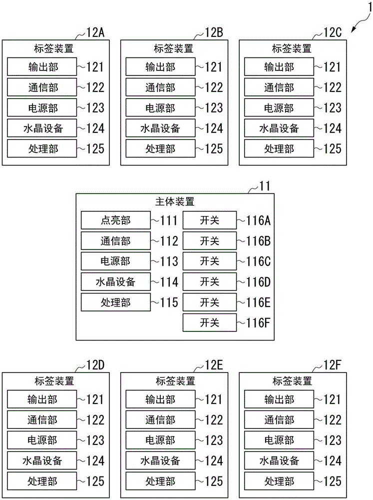
Fig. 1 is a diagram showing an example of an outline of a lost article finding system 1 according to embodiment 1.
In the example shown in fig. 1, the lost article search system 1 includes a main body device 11 and tag devices 12A to 12F. The tag devices 12A to 12F are configured to be separable from the main body device 11.
In the example shown in fig. 1, the lost article search system 1 includes 6 tag devices 12A to 12F, but in another example, the lost article search system 1 may include only 1 tag device 12A. In still another example, the lost article finding system 1 may include any number (but a plurality) of tag devices other than 6.
Fig. 2 is a diagram showing an example of the configuration of the main apparatus 11 shown in fig. 1.
In the example shown in fig. 1 and 2, the main body device 11 includes a lighting unit 111, a communication unit 112, a power supply unit 113, a crystal device 114, a processing unit 115, and switches 116A to 116F.
The lighting unit 111 includes, for example, an LED (light emitting diode) and can be turned on and off at a predetermined cycle (on/off speed). The communication unit 112 includes, for example, a pcb (printed Circuit board) antenna and has a function of transmitting and receiving radio wave signals. The power supply unit 113 includes, for example, a button cell battery, and supplies electric power to each component of the main body device 11. The crystal device 114 generates a reference signal, a synchronization signal, and the like.
The processing unit 115 includes, for example, a BLE (Bluetooth (registered trademark) Low Energy) chip. The processing unit 115 has a function of detecting the Received Signal Strength (RSSI) of the radio wave signal received by the communication unit 112, a function of setting the on/off period of the lighting unit 111, and the like.
In the example shown in fig. 1 and 2, the switches 116A to 116F are, for example, push-type (push-button type) switches, and are turned on while being pressed by the user of the lost article search system 1, and are turned off when not being pressed by the user of the lost article search system 1.
In detail, the switch 116A is pressed by the user of the lost article finding system 1 when the finding of the object to be found (for example, a wallet or the like) connected to the tag device 12A is performed. Similarly, the switches 116B to 116F are pressed by the user of the lost article finding system 1 when finding an object to be found (for example, a credit card or the like) connected to the tag devices 12B to 12F.
In another example, the switches 116A to 116F may be non-pressing switches such as slide switches. In this example, the switches 116A to 116F are turned on while the user of the lost article finding system 1 slides the switches 116A to 116F, and the switches 116A to 116F are turned off while the user of the lost article finding system 1 does not slide the switches 116A to 116F.
In the example shown in fig. 1 and 2, when the switch 116A is in the on state (during the on state), the communication unit 112 transmits a radio wave signal including an identification number unique to the tag device 12A. When the switch 116A is in the off state (during the period), the communication unit 112 does not transmit the radio wave signal including the unique identification number of the tag device 12A. That is, the switch 116A corresponds to the label device 12A. Similarly, when the switches 116B to 116F are in the on state (during the on period), the communication unit 112 transmits radio signals including the unique identification numbers of the tag devices 12B to 12F.
In the example shown in fig. 1 and 2, the main body device 11 does not include an output unit that outputs sound, but in another example, the main body device 11 may include an output unit (not shown) that outputs sound. In this example, the output unit of the main body device 11 outputs a sound in response to an operation on any of the tag devices 12A to 12F. In other words, in this example, each of the tag devices 12A to 12F includes an operation unit (not shown) that receives an operation for causing the output unit of the main body device 11 to output a sound.
Fig. 3 is a diagram showing an example of the configuration of the label device 12A (12B to 12F) shown in fig. 1. In the example shown in fig. 1 to 3, the tag devices 12B to 12F are configured similarly to the tag device 12A.
In other examples, the tag devices 12A to 12F may be configured differently from each other.
In the example shown in fig. 1 to 3, the tag device 12A (12B to 12F) includes an output unit 121, a communication unit 122, a power supply unit 123, a crystal device 124, and a processing unit 125. The output unit 121 includes, for example, a speaker and outputs a sound such as a beep sound.
The communication unit 122 includes, for example, a PCB antenna. The communication unit 122 has a function of receiving a radio wave signal transmitted from the communication unit 112 of the main apparatus 11 and a function of transmitting a radio wave signal.
The power supply unit 123 includes, for example, a button cell battery, and supplies power to the respective components of the label device 12A (12B to 12F). Crystal device 124 generates reference signals, synchronization signals, and the like.
The processing unit 125 includes, for example, a BLE chip. The processing unit 125 has a function of checking an identification number included in the radio wave signal received by the communication unit 122.
In the example shown in fig. 1 to 3, when the communication unit 122 of the tag device 12A receives the radio wave signal transmitted from the communication unit 112 of the main body device 11 and when the received radio wave signal includes the unique identification number of the tag device 12A (that is, when the switch 116A is in the on state), the output unit 121 of the tag device 12A outputs a sound such as a beep sound and the communication unit 122 of the tag device 12A transmits the radio wave signal. The output units 121 of the tag devices 12B to 12F do not output a sound such as a beep sound, and the communication units 122 of the tag devices 12B to 12F do not emit radio wave signals.
Specifically, when the communication unit 122 of the tag device 12A receives the radio wave signal transmitted from the communication unit 112 of the main device 11 and the received radio wave signal includes the unique identification number of the tag device 12A, the processing unit 125 of the tag device 12A detects the received signal strength of the received radio wave signal, and the output unit 121 of the tag device 12A outputs the sound at different intervals according to the received signal strength of the received radio wave signal.
In another example, the output unit 121 of the tag device 12A may output the sound at regular intervals regardless of the received signal strength of the radio wave signal received by the communication unit 122 of the tag device 12A.
Similarly, when the communication unit 122 of the tag devices 12B to 12F receives the radio wave signal transmitted from the communication unit 112 of the main body device 11 and when the received radio wave signal includes the unique identification numbers of the tag devices 12B to 12F (that is, when the switches 116B to 116F are in the on state), the output units 121 of the tag devices 12B to 12F output a sound such as a beep sound and the communication units 122 of the tag devices 12B to 12F transmit the radio wave signal.
In the example shown in fig. 1 to 3, when the communication unit 112 of the main body device 11 receives the radio wave signal transmitted from any of the communication units 122 of the tag devices 12A to 12F, the processing unit 115 of the main body device 11 detects the received signal strength of the radio wave signal transmitted from any of the communication units 122 of the tag devices 12A to 12F, and sets the on/off period of the lighting unit 111 of the main body device 11.
The higher the received signal strength of the radio wave signal transmitted from the communication unit 122 of any one of the tag devices 12A to 12F (that is, the closer the tag device (any one of the tag devices 12A to 12F) connected to the search target object is to the main body device 11), the shorter the on/off period of the lighting unit 111 of the main body device 11 is made by the processing unit 115 of the main body device 11 (that is, the faster the on/off speed of the lighting unit 111 of the main body device 11 is made).
The lighting unit 111 of the main body 11 is turned on and off at a lighting and off period set by the processing unit 115 of the main body 11. That is, the lighting unit 111 of the main body device 11 lights up and lights down at different periods according to the received signal strength of the radio wave signal transmitted from any one of the communication units 122 of the tag devices 12A to 12F.
Specifically, when the communication unit 112 of the main body device 11 receives the radio wave signal transmitted from the communication unit 122 of the tag device 12A, the processing unit 115 of the main body device 11 detects the received signal strength of the radio wave signal transmitted from the communication unit 122 of the tag device 12A, and the lighting unit 111 of the main body device 11 lights and turns on at different periods according to the received signal strength of the radio wave signal transmitted from the communication unit 122 of the tag device 12A (that is, according to the distance between the tag device 12A and the main body device 11).
Similarly, when the communication unit 112 of the main body device 11 receives the radio wave signals transmitted from the communication units 122 of the tag devices 12B to 12F, the processing unit 115 of the main body device 11 detects the reception signal intensities of the radio wave signals transmitted from the communication units 122 of the tag devices 12B to 12F, and the lighting unit 111 of the main body device 11 lights and turns off at different periods according to the reception signal intensities of the radio wave signals transmitted from the communication units 122 of the tag devices 12B to 12F.
Fig. 4 is a sequence diagram for explaining an example of processing executed in the lost-article finding system 1 according to embodiment 1. Specifically, fig. 4 is a sequence diagram for explaining an example of processing executed in the lost article finding system 1 according to embodiment 1 when finding an object to be found (e.g., a wallet or the like) connected to the tag device 12A.
In the example shown in fig. 4, in step S11, the switch 116A of the main device 11 is turned on by the user of the lost article search system 1. Specifically, the switch 116A of the main body device 11 remains in the on state until step S31 described later is executed.
Next, in step S12, when the switch 116A of the main apparatus 11 is turned on in step S11, the communication unit 112 of the main apparatus 11 transmits a radio wave signal including the unique identification number of the tag apparatus 12A (i.e., the tag apparatus 12A corresponding to the switch 116A).
Specifically, the communication unit 112 of the main body device 11 continuously transmits a radio wave signal including the unique identification number of the tag device 12A at predetermined time intervals while the switch 116A is in the on state.
Next, in step S13A, the communication unit 122 of the tag device 12A receives the radio signal (the radio signal including the unique identification number of the tag device 12A) transmitted from the communication unit 112 of the main device 11 in step S12.
In step S13B, the communication unit 122 of the tag devices 12B to 12F also receives the radio signal (that is, the radio signal including the unique identification number of the tag device 12A) transmitted from the communication unit 112 of the main body device 11 in step S12.
Next, in step S14A, the processing unit 125 of the tag device 12A confirms the identification number included in the radio signal received by the communication unit 122 of the tag device 12A in step S13A (that is, confirms that the radio signal includes the unique identification number of the tag device 12A).
In step S14B, the processing unit 125 of the tag devices 12B to 12F confirms the identification numbers included in the radio wave signals received by the communication unit 122 of the tag devices 12B to 12F in step S13B (that is, confirms that the radio wave signals do not include the unique identification numbers of the tag devices 12B to 12F).
Next, in step S15A, the output unit 121 of the tag device 12A outputs a sound such as a beep sound, based on the result of the confirmation in step S14A that the radio wave signal includes the unique identification number of the tag device 12A.
Specifically, the output unit 121 of the tag device 12A continuously outputs a sound such as a beep sound while a confirmation result indicating that the radio wave signal from the main device 11 includes the unique identification number of the tag device 12A is obtained (that is, while the switch 116A corresponding to the tag device 12A is in the on state).
In step S15B, output unit 121 of tag devices 12B to 12F does not output a sound such as a beep sound, based on the result of the confirmation in step S14B that the radio wave signal does not include the unique identification numbers of tag devices 12B to 12F.
Next, in step S16A, the communication unit 122 of the tag device 12A transmits a radio signal based on the result of the confirmation in step S14A that the radio signal includes the unique identification number of the tag device 12A.
Specifically, the communication unit 122 of the tag device 12A continues to emit the radio wave signal at predetermined time intervals while the confirmation result indicating that the radio wave signal from the main device 11 includes the unique identification number of the tag device 12A (that is, while the switch 116A corresponding to the tag device 12A is in the on state) is obtained.
In step S16B, communication unit 122 of tag devices 12B to 12F does not transmit a radio signal according to the result of the confirmation in step S14B that the radio signal does not include the unique identification numbers of tag devices 12B to 12F.
Next, in step S17, the communication unit 112 of the main body device 11 receives the radio wave signal transmitted from the communication unit 122 of the tag device 12A in step S16A.
Next, in step S18, the processing unit 115 of the main apparatus 11 detects the received signal strength of the radio signal received by the communication unit 112 of the main apparatus 11 in step S17.
Next, in step S19, the processing unit 115 of the main apparatus 11 sets the on/off period of the lighting unit 111 of the main apparatus 11 based on the received signal strength detected in step S18.
Next, in step S20, the lighting unit 111 of the main body device 11 starts lighting in and out in the lighting-in and-out period set in step S19.
Specifically, the lighting unit 111 of the main body device 11 is continuously turned on and off while the radio wave signal transmitted from the communication unit 122 of the tag device 12A is received by the communication unit 112 of the main body device 11 (i.e., while the switch 116A corresponding to the tag device 12A is in the on state).
The lost article finding system 1, which finds a finding object (for example, a wallet or the like) connected to the tag device 12A, moves while continuously pressing the switch 116A of the main body device 11 and confirming the sound such as a beep sound outputted from the output unit 121 of the tag device 12A and the on/off of the lighting unit 111 of the main body device 11.
As a result, the distance between the main body device 11 and the tag device 12A changes, and the received signal strength of the radio wave signal from the tag device 12A detected by the processing unit 115 of the main body device 11 changes. The received signal strength of the radio wave signal from the main apparatus 11 detected by the processing unit 125 of the tag apparatus 12A also changes.
In the example shown in fig. 4, in step S21, the processing unit 115 of the main body device 11 detects the received signal strength (change in received signal strength) of the radio wave signal transmitted from the communication unit 122 of the tag device 12A.
Next, in step S22, the processing unit 115 of the main apparatus 11 sets (changes) the on/off period of the lighting unit 111 of the main apparatus 11 based on the received signal strength (change in received signal strength) detected in step S21.
Next, in step S23, the lighting unit 111 of the main body device 11 is turned on and off at the on and off period set (changed) in step S22.
If the user of the lost article finding system 1 finds a finding target article (a finding target article connected to the tag device 12A), the user does not press the switch 116A of the main body device 11 any more.
In the example shown in fig. 4, in step S31, the switch 116A of the main device 11 is turned off by the user of the lost article search system 1.
Next, in step S32, when the switch 116A of the main apparatus 11 is turned off in step S31, the communication unit 112 of the main apparatus 11 stops the transmission of the radio signal including the unique identification number of the tag apparatus 12A (i.e., the tag apparatus 12A corresponding to the switch 116A).
In step S32, as the communication unit 112 of the main apparatus 11 stops transmitting the radio signal including the unique identification number of the tag apparatus 12A, the communication unit 122 of the tag apparatus 12A does not receive the radio signal including the unique identification number of the tag apparatus 12A in step S33A.
In step S33B, the communication unit 122 of the tag devices 12B to 12F does not receive any radio wave signal including the unique identification number of the tag device 12A.
In step S33A, as the communication unit 122 of the tag device 12A no longer receives the radio wave signal including the unique identification number of the tag device 12A, the output unit 121 of the tag device 12A stops outputting the sound such as the beep sound in step S34A.
In step S34B, the output units 121 of the tag devices 12B to 12F maintain the stop state of the output of the sound such as the beep sound.
In step S33A, as the communication unit 122 of the tag device 12A no longer receives the radio signal including the unique identification number of the tag device 12A, the communication unit 122 of the tag device 12A stops transmission of the radio signal in step S35A.
In step S35B, the communication unit 122 of the tag devices 12B to 12F maintains a state in which no radio wave signal is emitted.
As the communication unit 122 of the tag device 12A stops transmitting the radio signal in step S35A and the communication units 122 of the tag devices 12B to 12F maintain a state in which the radio signal is not transmitted in step S35B, the communication unit 112 of the main device 11 does not receive the radio signal any more in step S36.
In step S36, as the communication unit 112 of the main apparatus 11 no longer receives the radio signal, the lighting unit 111 of the main apparatus 11 ends lighting (i.e., goes out) in step S37.
< application example 1 >
Fig. 5 and 6 are diagrams for explaining an application example 1 of the lost article search system 1 according to embodiment 1. Specifically, (a) of fig. 5 is a perspective view of the lost article search system 1 of the 1 st application example in which the tag devices 12A to 12F are stored in the main body device 11. Fig. 5 (B) is a perspective view of the lost article search system 1 of the 1 st application example in which the tag devices 12A to 12F are slid from the state shown in fig. 5 (a). Fig. 6 (a) is a plan view of the lost article searching system 1 of the application example 1 placed on the palm of the user of the lost article searching system 1. Fig. 6 (B) is a right side view of the lost article searching system 1 of the 1 st application example in a state of being placed on the palm of the user of the lost article searching system 1.
In the example shown in fig. 5 and 6, the tag devices 12A to 12F are configured to be slidable with respect to the main body device 11.
In the case where the tag devices 12A to 12F are not used (i.e., in the case where the tag devices 12A to 12F are not connected to the search target object), the tag devices 12A to 12F are stored in the main body device 11 as shown in fig. 5 (a). As a result, the switches 116A to 116F of the main body device 11 are covered with the label devices 12A to 12F. Therefore, it is possible to suppress the possibility of the switches 116A to 116F being turned on and the power being consumed due to an erroneous operation by the user of the lost article finding system 1.
For example, when all of the tag devices 12A to 12F are used, the tag devices 12A to 12F are slid as shown in fig. 5 (B). As a result, the switches 116A to 116F of the main body device 11 are exposed. Therefore, the user of the lost article finding system 1 can find the finding target object connected to the tag device 12A by pressing the switch 116A corresponding to the tag device 12A to turn on, for example.
The dimensions of the lost article finding system 1 of the application 1 are set to the palm dimensions of the user of the lost article finding system 1, as shown in fig. 6 (a) and 6 (B). That is, the lost article finding system 1 of the 1 st application example is set to a size such that a user of the lost article finding system 1 can easily hold the lost article finding system 1 (the main body device 11).
Fig. 7 is a diagram showing an example of a method of using the tag devices 12A and 12B of the lost article search system 1 according to application 1.
In the example shown in fig. 7, the label device 12A is mounted on a wallet as a pendant.
In the example shown in fig. 5 to 7, the label device 12A and the switch 116A have the 1 st color. The label device 12B and the switch 116B have a 2 nd color different from the 1 st color. The label device 12C and the switch 116C have a 3 rd color different from the 1 st color and the 2 nd color.
The label device 12D and the switch 116D have a 4 th color different from the 1 st, 2 nd, and 3 rd colors. The label device 12E and the switch 116E have a 5 th color different from the 1 st, 2 nd, 3 rd, and 4 th colors. The label device 12F and the switch 116F have a 6 th color different from the 1 st, 2 nd, 3 rd, 4 th, and 5 th colors.
In another example, the label devices 12A to 12F may have different patterns, and the switches 116A to 116F may have patterns corresponding to the label devices 12A to 12F.
In yet another example, the tag devices 12A to 12F may have different characters, and the switches 116A to 116F may have characters corresponding to the tag devices 12A to 12F.
In yet another example, the label devices 12A to 12F may have different labels, and the switches 116A to 116F may have labels corresponding to the label devices 12A to 12F.
In these examples, the user of the lost article finding system 1 can easily grasp the correspondence relationship between the tag devices 12A to 12F and the switches 116A to 116F.
In the example shown in fig. 5 to 7, if the communication unit 122 of the tag device 12A receives the radio wave signal transmitted from the communication unit 112 of the main device 11 when the switch 116A is in the on state, the output unit 121 of the tag device 12A outputs a beep sound.
Further, if the communication unit 112 of the main apparatus 11 receives the radio wave signal transmitted from the communication unit 122 of the tag apparatus 12A, the lighting unit 111 of the main apparatus 11 lights up and off at a cycle set according to the received signal strength of the radio wave signal transmitted from the communication unit 122 of the tag apparatus 12A. If the distance between the main body device 11 and the tag device 12A changes and the received signal strength of the radio wave signal transmitted from the communication unit 122 of the tag device 12A changes, the lighting unit 111 of the main body device 11 lights up and off at a cycle set according to the changed received signal strength.
For example, if the user of the lost article finding system 1 holding the main body device 11 approaches the tag device 12A, the received signal strength increases, and the on-off period of the lighting portion 111 of the main body device 11 becomes short (i.e., the on-off speed becomes fast).
On the other hand, if the user of the lost article finding system 1 holding the main body device 11 moves away from the tag device 12A, the received signal strength decreases, and the on-off period of the lighting portion 111 of the main body device 11 becomes longer (i.e., the on-off speed becomes slower).
In the example shown in fig. 5 to 7, when the label device 12A is in the on state, the lighting portion 111 of the main body device 11 is turned on and off in the 1 st color, and when the label devices 12B to 12F are in the on state, the lighting portion 111 is turned on and off in the 2 nd to 6 th colors.
In another example, the lighting unit 111 of the main body device 11 may emit 1 color of light.
< application example 2 >
Fig. 8 is a diagram for explaining a 2 nd application example of the lost article search system 1 according to embodiment 1. Specifically, (a) of fig. 8 is a perspective view of the lost article search system 1 of application example 2 in which the tag devices 12A to 12F are not separated from the main body device 11. Fig. 8 (B) is a perspective view of the lost article search system 1 of the 2 nd application example in a state where the tag devices 12A to 12F are separated from the main body device 11.
In the example shown in fig. 8, the main body device 11 and the tag devices 12A to 12F of the lost article finding system 1 are detachably (detachably) configured by snap fitting (snap fit).
In the case where the tag devices 12A to 12F are not used (that is, in the case where the tag devices 12A to 12F are not connected to the search target object), the tag devices 12A to 12F are coupled to the main body device 11 by snap-fitting as shown in fig. 8 (a). Therefore, the user of the lost-article finding system 1 can suppress the possibility of losing the tag devices 12A to 12F that are not used.
For example, when all of the tag devices 12A to 12F are used, the tag devices 12A to 12F are separated from the main body device 11 as shown in fig. 8 (B). The user of the lost article finding system 1 can find the finding target article connected to the tag device 12A by pressing the switch 116A corresponding to the tag device 12A to turn on, for example.
As described above, in the lost article finding system 1 according to embodiment 1, the communication unit 122 of the tag devices 12A to 12F transmits a radio wave signal when receiving the radio wave signal transmitted from the communication unit 112 of the main body device 11. When the communication unit 112 of the main body device 11 receives the radio wave signals transmitted from the communication units 122 of the tag devices 12A to 12F, the processing unit 115 of the main body device 11 detects the received signal strength of the radio wave signals transmitted from the communication units 122 of the tag devices 12A to 12F. Further, the lighting unit 111 of the main body device 11 lights up and off at different periods according to the received signal strength of the radio wave signal transmitted from the communication unit 122 of the tag devices 12A to 12F.
Therefore, the user of the lost article finding system 1 can easily use the lost article finding system 1 even in the case of, for example, an elderly person.
In the lost article finding system 1 according to embodiment 1, for example, the communication unit 112 of the main body device 11 does not emit a radio wave signal including the unique identification number of the tag device 12A corresponding to the switch 116A when the switch 116A is in the off state, and emits a radio wave signal including the unique identification number of the tag device 12A corresponding to the switch 116A when the switch 116A is in the on state. Therefore, in the lost article finding system 1 according to embodiment 1, it is possible to suppress the possibility that the radio wave signal is emitted and the power is consumed when the tag device 12A does not need to be found.
In the lost article finding system 1 according to embodiment 1, for example, the switch 116A corresponds to 1 tag device 12A of the plurality of tag devices 12A to 12F, and the plurality of tag devices 12A to 12F have unique identification numbers different from each other.
Specifically, in the lost article finding system 1 according to embodiment 1, for example, the radio wave signal transmitted from the communication unit 112 of the main body device 11 when the switch 116A is in the on state includes the identification number of the tag device 12A corresponding to the switch 116A among the plurality of tag devices 12A to 12F. When the communication unit 122 of the tag device 12A corresponding to the switch 116A receives the radio signal (the radio signal including the unique identification number of the tag device 12A) transmitted from the communication unit 112 of the main device 11 when the switch 116A is in the on state, the radio signal is transmitted. Further, when the communication unit 112 of the main body device 11 receives the radio wave signal transmitted from the communication unit 122 of the tag device 12A corresponding to the switch 116A, the processing unit 115 of the main body device 11 detects the received signal intensity of the radio wave signal transmitted from the communication unit 122 of the tag device 12A corresponding to the switch 116A, and the lighting unit 111 of the main body device 11 lights up and lights down at different periods according to the received signal intensity of the radio wave signal transmitted from the communication unit 122 of the tag device 12A corresponding to the switch 116A.
Therefore, the user of the lost article finding system 1 can grasp the distance between the tag device 12A corresponding to the switch 116A that is turned on by the user of the lost article finding system 1 among the plurality of tag devices 12A to 12F and the main body device 11, from the on/off cycle of the lighting portion 111 of the main body device 11.
< embodiment 2 >
Hereinafter, embodiment 2 of the lost article finding system, the tag device, and the program according to the present invention will be described.
The lost article search system 1 according to embodiment 2 is configured in the same manner as the lost article search system 1 according to embodiment 1, except for the points described below. Therefore, according to the lost article finding system 1 of embodiment 2, the same effects as those of the lost article finding system 1 of embodiment 1 can be obtained except for the points described later.
As described above, in the lost article finding system 1 according to embodiment 1, the main device 11 is a dedicated device constituting a part of the lost article finding system 1, whereas in the lost article finding system 1 according to embodiment 2, the main device 11 is a general-purpose terminal device carried by a user of the lost article finding system 1, such as a smart phone or a mobile phone.
In the lost article finding system 1 according to embodiment 2, for example, a display of a smart phone, a mobile phone, or the like is used as the lighting unit 111 of the main device 11. The communication unit 112 of the main body device 11 is, for example, a short-range wireless communication function provided in a smart phone, a mobile phone, or the like. Further, as the processing unit 115 of the main body device 11, for example, a processor or the like built in a smart phone, a mobile phone, or the like is used.
In the lost article finding system 1 according to embodiment 2, for example, buttons on a touch panel of a smart phone, a numeric keypad of a mobile phone, and the like are used as the switches 116A to 116F of the main body device 11.
Further, in the lost article finding system 1 according to embodiment 2, the tag devices 12A to 12F have a function of transmitting their own unique identification numbers to the main device 11, for example, a smart phone, a mobile phone, or the like.
< modification example >
Fig. 9 is a diagram showing an improvement in structure as a modification of the main unit 11, and is a perspective view of the lost article search system 1 of the first application example 1 in a state where the tag devices 12A to 12F are stored in the main unit 11. In the lost article finding system 1 according to embodiment 1 described above, for example, as shown in fig. 5, the switches 116A to 116F of the main body apparatus 11 are push-type (push-button type) switches, but are changed to electrostatic switches.
In the case where the switch is a push button switch that is normally pushed, it is difficult for the elderly to continuously push the switch while holding the device. For example, it is difficult for the elderly to perform such an operation that the switch is continuously pressed when searching for an article and is opened once searching is completed. Therefore, the switch is changed to an electrostatic switch. An electrostatic switch is a common component used by a smartphone or the like. Even if the electrostatic switch is not pressed, only a finger (only touch) is put on the electrostatic switch. Therefore, usability is improved.
As shown in fig. 9, a circular shape 216C is formed in a part of the cover of the electrostatic switch, and the electrostatic switch is exposed inside the circular shape. The circular shape 216C of fig. 9 shows the exposed electrostatic switch. Since a person has a sense of pressing the circular shape, the old person can feel the sense of touching the circular electrostatic switch by forming the circular shape. As described above, when the cared person holds the apparatus and the cared person searches for an article together, there is an advantage that the cared person can easily hold the apparatus and use it.
While the embodiments have been described above as the embodiments for carrying out the present invention, the present invention is not limited to the embodiments, and various modifications and substitutions can be made without departing from the scope of the present invention. The configurations described in the above embodiments and examples may be appropriately combined.
The whole or a part of the functions of each unit provided in the lost article finding system 1 according to the above-described embodiment may be realized by recording a program for realizing these functions in a computer-readable recording medium, and causing a computer system to read and execute the program recorded in the recording medium. The "computer system" described herein includes hardware such as an OS and peripheral devices.
The "computer-readable recording medium" refers to a removable medium such as a flexible disk, a magneto-optical disk, a ROM, and a CD-ROM, and a storage unit such as a hard disk incorporated in a computer system. Further, the "computer-readable recording medium" may include a medium that dynamically holds a program for a short time, such as a communication line in the case where the program is transmitted via a network such as the internet or a communication line such as a telephone line, and a medium that holds a program for a certain time, such as a volatile memory inside a computer system serving as a server or a client in this case. Further, the above-described program may be used to realize a part of the above-described functions, and the above-described functions may also be realized by a combination with a program already recorded in a computer system.
Description of the reference numerals
1 … lost article finding system; 11 … a main body device; 111 … lighting part; 112 … communication section; 113 … a power supply section; 114 … crystal device; 115 … processing part; 116a … switch; 116B … switch; a 116C … switch; 116D … switch; 116E … switch; 116F … switch; 12a … label device; 12B … label device; 12C … label device; 12D … tag device; 12E … label device; 12F … label device; 121 … output; 122 … a communication section; 123 … power supply section; 124 … crystal device; 125 … processing unit.