Detailed Description
For the avoidance of doubt, the composite oxidation catalyst described herein is referred to as an "oxidation catalyst" because it can oxidize pollutants in the exhaust gas during normal lean burn operation of the compression ignition engine, which produces lean exhaust gas, primarily carbon monoxide and unburned hydrocarbons. The composite oxidation catalyst may also oxidize nitric oxide in the exhaust gas to nitrogen dioxide to promote downstream catalytic activity such as

Effects and/or promotes selective catalytic reduction reactions and such NO oxidation activity may be enhanced by using the features of one or more of the appended dependent claims. Since the composite oxidation catalyst is preferably used inExhaust gas produced by diesel compression ignition engines is considered and may therefore also be referred to as "diesel oxidation catalysts". In rare cases, however, the composite oxidation catalyst according to the invention is intended to generate an exotherm from the additional hydrocarbons introduced into the exhaust gas, thereby heating the downstream particulate filter and thereby regenerating it (i.e. burning the soot trapped thereon (active regeneration)).
The activity of the composite oxidation catalyst is not limited to oxidation reactions, but the oxidation catalyst should be capable of oxidizing one or more pollutants in the exhaust gas of a compression ignition engine during normal lean burn operation. For example, given appropriate conditions, the oxidation catalyst is additionally capable of performing a reduction reaction, such as the reduction of Nitrogen Oxides (NO) using hydrocarbons in the exhaust gas as a reducing agentx) (so-called lean NO)xCatalytic, DeNOxCatalytic or hydrocarbon-SCR) and/or capable of temporarily storing one or more pollutants from the exhaust gas, such as NOxAnd/or temporary adsorption of hydrocarbons. For further avoidance of doubt, the use of a composite oxidation catalyst to generate an exotherm from additional hydrocarbon fuel injected into the exhaust gas is not "normal use" (see discussion of regeneration frequency in the background section above). That is, "normal lean operation" is the time interval between heat release generating events.
With respect to NO oxidation activity, it is preferred that the composite oxidation catalyst as a whole is within the operating window of the oxidation catalyst during normal use>10% (such as>20%、>30%、>40% or>50%) to promote NO oxidation. This is in sharp contrast to the oxidation catalyst disclosed in WO2009/076574 discussed above, wherein the diesel oxidation catalyst is effective to produce substantially NO additional NO in the exhaust gas stream after passing through the diesel oxidation catalyst within about 90% of the operating window of the diesel oxidation catalyst2. The composite oxidation catalyst according to the present invention does this by including at least one zone in the oxidation catalyst, the at least one zone having>1 (such as>1.5:1 or>2:1), optionally platinum alone as the only platinum group metal present in that particular zone, i.e., a platinum to palladium weight ratio of 1:0 (or "infinity" (∞)). Optionally, for catalyst washcoat other than the first catalyst washcoat zoneLayer regions, such other regions may exhibit increased NO oxidation in the presence of lower alkaline earth metal loading or the substantial absence of alkaline earth metal in one or more regions other than the first catalyst washcoat region.
According to the first aspect, the second catalyst washcoat zone may be defined at a second end thereof by a second substrate end. That is, the composite oxidation catalyst as a whole includes two catalyst washcoat zones (see, e.g., the arrangement shown in fig. 1).
Methods of making such catalysts having two catalyst washcoat zones include the method according to the sixth inventive aspect, wherein in step (a) the catalyst washcoat extends along the total length L of the substrate. It will be appreciated that in this process the first refractory metal oxide support material is the same as the second refractory metal oxide support material. Alternatively, the composite oxidation catalyst shown in fig. 1 may be obtained or obtainable by coating a substrate (5) from a first end thereof in either order: coated to an axial length L with a first catalyst washcoat1(see item 9 in fig. 1) for forming a first washcoat catalyst region and comprising a first refractory metal oxide support material, two or more platinum group metal components comprising both platinum and palladium, and one or more alkaline earth metal components; and coated with a second, different catalyst washcoat layer comprising a second refractory metal oxide support material and one or more second platinum group metals and optionally one or more second alkaline earth metal components for forming a catalyst having an axial length L2Such that the second end (13) of the first catalyst washcoat (9) and the first end (15) of the second catalyst washcoat (11) abut one another without substantially any overlap between the first washcoat and the second washcoat. In the latter method of making the embodiment of fig. 1, it will be appreciated that the axial length L of the first catalyst washcoat zone1Is the same or substantially the same as the axial length of the first catalyst washcoat layer (9); and the axial length L of the second catalyst washcoat zone2And the axial length L of the second catalyst washcoat zone2Identical or substantially identical. More details of the method of preparing the dual zone composite oxidation catalyst according to the first inventive aspect are described above in connection with fig. 1.
Alternatively, according to the first aspect, the composite oxidation catalyst may comprise three or more catalyst washcoat zones, wherein a third catalyst washcoat zone comprising a third refractory metal oxide support material and one or more platinum group metal components supported thereon is defined at a second end thereof by a second substrate end, and wherein the platinum group metal in grams per cubic foot of substrate volume (g/ft) in the third catalyst washcoat zone3) The defined total platinum group metal loading is less than the total platinum group metal loading in the second catalyst washcoat region.
The composite oxidation catalyst according to the first aspect of the present invention may comprise four catalyst washcoat zones, wherein a fourth catalyst washcoat zone is located between the second and third catalyst washcoat zones, the fourth catalyst washcoat zone comprising a fourth refractory metal oxide support material and one or more platinum group metal components supported thereon and being defined at a first end thereof by a second end of the second catalyst washcoat zone and at a second end thereof by a first end of the third catalyst washcoat zone, and wherein the platinum group metal in the fourth catalyst washcoat zone is in grams per cubic foot of substrate volume (g/ft)3) The defined total platinum group metal loading is greater than the total platinum group metal loading in each of the second and third catalyst washcoat regions.
Preferably, in a composite oxidation catalyst according to the first aspect of the present invention comprising four catalyst washcoat zones, the composite oxidation catalyst comprises a first catalyst washcoat layer and a second catalyst washcoat layer, wherein the first catalyst washcoat layer comprises a refractory metal oxide support material and one or more platinum group metal components supported thereon and has a length L3Wherein L is3<L and is defined at one end by a first base end; and isThe second catalyst washcoat layer comprises a refractory metal oxide support material and one or more platinum group metal components supported thereon and having a length L4Wherein L is4<L and is defined at the second end by a second substrate end, wherein the fourth catalyst washcoat region includes a dual-layer overlap region of the first catalyst washcoat and the second catalyst washcoat, and wherein the third catalyst washcoat region includes a single layer of the second catalyst washcoat that does not constitute the overlap region. Methods of making such composite oxidation catalysts are described above with reference to the embodiments shown in fig. 3 and 5 and with further reference to the embodiments shown in fig. 2 and 4 and their associated descriptions.
A composite oxidation catalyst including three catalyst washcoat zones may include a third catalyst washcoat zone defined at a first end thereof by a second end of a second catalyst washcoat zone (see, e.g., the arrangements shown in fig. 2 and 4).
Such composite oxidation catalysts may include a first catalyst washcoat layer and a second catalyst washcoat layer, wherein the first catalyst washcoat layer comprises a refractory metal oxide support material and one or more platinum group metal components supported thereon having a length L3Wherein L is3<L and is defined at one end by a first base end; and the second catalyst washcoat layer comprising a refractory metal oxide support material and one or more platinum group metal components supported thereon, having a length L4Wherein L is4<L and is defined at the second end by a second substrate end, wherein the second catalyst washcoat region includes a dual-layer overlap region of the first catalyst washcoat layer and the second catalyst washcoat layer, and wherein the third catalyst washcoat region includes a single layer of the second catalyst washcoat layer that does not constitute the overlap region.
In the three-zone and four-zone arrangements described above, preferably, the one or more platinum group metal components in the third catalyst washcoat zone consist essentially of platinum. It will be appreciated that where the one or more platinum group metals in the third catalyst washcoat zone consists essentially of platinum, in an arrangement characterized by an overlap of the first catalyst washcoat and the second catalyst washcoat, the second catalyst washcoat forming the third catalyst washcoat zone also consists essentially of platinum.
It will also be appreciated that in a composite oxidation catalyst having two zones as described herein, the second catalyst washcoat zone may comprise one or more alkaline earth metals, such as barium and/or strontium, preferably barium.
It will also be appreciated that in a composite oxidation catalyst having three zones as described herein, the second catalyst washcoat zone, the third catalyst washcoat zone, or both the second catalyst washcoat zone and the third catalyst washcoat zone may each comprise one or more alkaline earth metals, such as barium and/or strontium, preferably barium.
It will also be appreciated that in a composite oxidation catalyst having four zones as described herein, the second, third and/or fourth catalyst washcoat zones may each comprise one or more alkaline earth metals, such as barium and/or strontium, preferably barium.
It will also be appreciated that in a composite oxidation catalyst having three zones or four zones as described herein, the first catalyst washcoat, the second catalyst washcoat and/or both the first catalyst washcoat and the second catalyst washcoat may each comprise one or more alkaline earth metals, such as barium and/or strontium, preferably barium.
A method of preparing a three-zone or four-zone composite oxidation catalyst according to the invention comprises a method according to the sixth inventive aspect, wherein in step (a) the catalyst washcoat is a first catalyst washcoat extending from a first substrate end to less than the total length of the substrate, the method further comprising step (a') before step (a) or after step (a), but in either case before step (b), in step (b) a second catalyst washcoat is applied to the substrate for a length extending from a second substrate end to less than the total length of the substrate such that the first catalyst washcoat partially overlaps the second catalyst washcoat or the second catalyst washcoat partially overlaps the first catalyst washcoat, wherein the second catalyst washcoat comprises a refractory metal oxide support material and one or more platinum group metal components, it is to be understood that the platinum group metal composition of the washcoat catalyst zone comprising two overlapping layers comprises the total platinum group metal present in each of the two overlapping layers of the zone.
In the case where the above-described method is used to prepare a composite oxidation catalyst having three or more zones according to the present invention, it will be appreciated that the axial length L of the impregnation step is1The number of catalyst washcoat zones present along the axial substrate length can be determined. This is further explained with reference to fig. 2, 3, 4 and 5 herein.
Wherein L is1Less than the axial length between the first substrate end and the first end of the second catalyst washcoat, representing the end of the overlap region of the first catalyst washcoat and the second catalyst washcoat, the second catalyst washcoat zone comprising a single layer of the first catalyst washcoat, the second catalyst washcoat zone being bounded at one end by a first catalyst washcoat zone L1And is defined at the second end by a first end of the overlap region of the first catalyst washcoat layer and the second catalyst washcoat layer that is closest to the first substrate end. In this case, the fourth catalyst washcoat zone is defined by a first end of the overlap region of the first washcoat and the second washcoat layer closest to the first substrate end with respect to the platinum group metal loading (g/ft) contained therein3) In other words, the first catalyst washcoat zone>Fourth catalyst washcoat zone>A second catalyst washcoat zone. The third catalyst washcoat zone is defined at the second end by the end of the substrate opposite the end of the substrate from which the first catalyst washcoat extends and at the first end by the end of the overlapping region of the first and second catalyst washcoats closest to the end from which the second catalyst washcoat extends (i.e., also corresponding to the second end of the fourth catalyst washcoat zone). This is achieved bySuch an arrangement is shown in fig. 3 and 5 herein.
Wherein L is1The oxidation catalyst as a whole comprises three axially disposed catalyst washcoat zones, which may be numbered sequentially from the first substrate end as a first catalyst washcoat zone, a second catalyst washcoat zone and a third catalyst washcoat zone, for a length equal to the axial length of a single layer of the first catalyst washcoat, which length extends from the first substrate end until the first catalyst washcoat enters the overlap region of the second catalyst washcoat zone.
Alternatively, the oxidation catalyst having three or more catalyst washcoat regions according to the present invention may be prepared by modifying the method for preparing an oxidation catalyst having two catalyst washcoat regions as described above according to the sixth aspect of the invention as follows. First, the substrate is coated with a first catalyst washcoat along its total length L. Second, a second catalyst washcoat layer comprising a refractory metal oxide support material and one or more platinum group metal components may be applied from the first substrate end on top of the first catalyst washcoat layer to an axial length less than the total substrate length L, or the first catalyst washcoat layer may be impregnated from the first substrate end to a length less than the total substrate length L with an impregnation solution comprising one or more platinum group metal salts and optionally one or more alkaline earth metal salts. The second catalyst washcoat or impregnated first catalyst washcoat will partially form the middle or second of the three catalyst washcoat zones disposed axially along the substrate. Third, as the first catalyst washcoat region L1A third catalyst washcoat layer comprising a refractory metal oxide support material and one or more platinum group metal components of (a) may be coated from the end of the first substrate (or at the zone length L) on top of the second catalyst washcoat layer1Impregnation onto the first washcoat layer corresponding to the first catalyst washcoat zone) to less than the axial length of the second catalyst washcoat layer or the axial length of the first impregnation of the second step described above. It should be understood that the term L is only used for1Of the layer and impregnating solution as a wholeAnd both platinum and palladium are included in a weight ratio of 1 or more, then the first catalyst washcoat region L1The platinum group metal content of (a) includes a combination of the following platinum group metal compositions of the first catalyst washcoat, second catalyst washcoat or impregnation solution, and third catalyst washcoat or impregnation solution. The one or more alkaline earth metal components may be present in the washcoat or impregnation step of the first, second and/or third application step.
Preferably, at least the third step is carried out as an impregnation up to a length L corresponding to step (b) of the sixth inventive aspect1. This is because the multilayer LbL coating reduces the cross-sectional area of the open face region of the substrate that is used to allow gas to pass through, thereby undesirably increasing the backpressure in the system. Thus, composite oxidation catalysts are preferred wherein at least one catalyst washcoat zone is formed by an underlying impregnation step of a catalyst washcoat, preferably the third step corresponding to the formation of the first catalyst washcoat zone.
In an exhaust system for a vehicular compression ignition engine, the first substrate end of the oxidation catalyst according to the first aspect of the invention comprising the first catalyst washcoat zone is oriented to the upstream side, i.e. closest to the engine. That is, the first substrate end may be defined as a first upstream inlet substrate end, and the second substrate end may be defined as a second downstream substrate (or outlet) end.
Platinum group metal loading
Generally, each catalyst washcoat zone in the composite oxidation catalyst according to the invention comprises one or more, or two or more platinum group metal components selected from platinum, palladium, rhodium, iridium, ruthenium, and mixtures or alloys of any two or more thereof, except in the case of a first catalyst washcoat zone comprising both platinum and palladium according to the first aspect of the invention, the weight ratio of platinum to palladium being ≧ 1. Wherein the catalyst washcoat zone-except the first catalyst washcoat zone-contains only one platinum group metal, preferably platinum, i.e., one or more platinum group metal components consists essentially of or consists of platinum.
In particular, the two or more platinum group metal components in the first catalyst washcoat zone and/or the first catalyst washcoat layer include both platinum and palladium, e.g., the two or more platinum group metal components consist essentially of or consist of platinum and palladium. Preferably, the only platinum group metals present in the first catalyst washcoat zone and/or the first catalyst washcoat layer are platinum and palladium. It should be understood that where the first catalyst washcoat layer comprises both platinum and palladium, any catalyst washcoat zone comprising the first catalyst washcoat layer will also comprise platinum and palladium.
It is further preferred that the one or more platinum group metal components in the second catalyst washcoat region comprise (i.e., intentionally comprise) platinum, such as both platinum and palladium, or the platinum may be the only platinum group metal present in the second catalyst washcoat region, e.g., the one or more platinum group metal components in the second catalyst washcoat region consist of platinum; or the more than one platinum group metal component in the second catalyst washcoat zone is comprised of both platinum and palladium. Optionally, the second catalyst washcoat region has a platinum content greater than 1 wt.% of the total metals in the region, including platinum group metals and base metals (e.g., alkaline earth metals), supported on the refractory metal oxide support material. This feature is intended to distinguish the disclosure of WO2009/076574, which is acknowledged in the background section above.
Preferably, where the substrate includes three or more catalyst washcoat zones, the third catalyst washcoat zone or the second catalyst washcoat zone may include platinum, i.e., intentionally include both platinum, such as platinum and palladium, or the platinum may be the only platinum group metal present in the third catalyst washcoat zone or the second catalyst washcoat. Optionally, the platinum content in a region of the third catalyst washcoat is greater than 1 wt.% of the total metals in that region, including platinum group metals and base metals (e.g., alkaline earth metals), supported on the refractory metal oxide support material. This feature is intended to distinguish the disclosure of WO2009/076574, which is acknowledged in the background section above.
In a preferred arrangement, the platinum is the only platinum group metal in the second catalyst washcoat, i.e., the one or more platinum group metal components in the second catalyst washcoat consist of platinum (Pt: Pd weight ratio of 1:0), as this feature provides for more stable NO operation of downstream catalyst functions2Particularly in arrangements in which the second catalyst washcoat layer overlaps the first catalyst washcoat layer, as shown in fig. 4 and 5. Thus, for stable NO2An arrangement is preferred wherein the one or more platinum group metal components in the second catalyst washcoat layer consists of platinum, wherein the second catalyst washcoat layer overlaps the first catalyst washcoat layer. In a preferred arrangement where platinum is the only platinum group metal present in the third catalyst washcoat zone or the second catalyst washcoat (i.e., a Pt: Pd weight ratio of 1:0), the third catalyst washcoat zone or the second catalyst washcoat layer comprises manganese (see below).
Preferably, the second catalyst washcoat zone comprises both platinum and palladium, e.g., more than one platinum group metal component in the second catalyst washcoat zone consists of platinum and palladium because this feature improves hydrocarbon slip control.
Thus, in general, to distinguish the disclosure of WO2009/076574, recognized in the background section above, any catalyst washcoat zone defined by the second (outlet) end of the substrate at the second end of the catalyst washcoat zone intentionally comprises platinum, wherein, optionally, the content of platinum in the catalyst washcoat zone is greater than 1 wt.% of the total metals in the zone, including platinum group metals and base metals (e.g., alkaline earth metals), supported on the refractory metal oxide support material.
Typically, the total platinum group metal loading (calculated as elemental metal) on the substrate as a whole is from 5 to 60g/ft3Preferably 8 to 50g/ft3For application to heavy duty diesel engine exhaust systems.
The weight ratio of Pt to Pd on the substrate as a whole (calculated as elemental metal) is preferably from 3:2 to 9:1, preferably from 2:1 to 7:1, most preferably from 3:1 to 5: 1.
The platinum group metal loading (calculated as elemental metal) in the first catalyst washcoat zone is preferably less than 100g/ft3Preferably 25-75g/ft3And most preferably 35-65g/ft3. It should be understood that the first catalyst washcoat zone may comprise the "underlying" platinum group metal loading in a first catalyst washcoat (typically a single layer of the first catalyst washcoat) which is subsequently impregnated with a high concentration solution of a platinum group metal salt prior to drying and calcination. Thus, the first catalyst washcoat zone is a combination of platinum group metal loadings from both the first catalyst washcoat and the impregnation solution.
The platinum group metal loading in the second and subsequent catalyst washcoat zones as a whole, i.e., the total platinum group metal (calculated as elemental metal) in the catalyst washcoat zones other than the first catalyst washcoat zone, may depend on the embodiment used. Thus, for example, in embodiments including only two zones in total, such as shown in FIG. 1, the total platinum group metal loading in the second catalyst washcoat zone is preferably 1 to 10g/ft3。
However, in embodiments including three catalyst washcoat zones, wherein the second catalyst washcoat zone includes an overlapping region of the first catalyst washcoat and the second catalyst washcoat (e.g., see embodiments in fig. 2 and 4) -or an embodiment including four catalyst washcoat zones, wherein the fourth catalyst washcoat zone includes an overlapping region of the first catalyst washcoat and the second catalyst washcoat (e.g., see embodiments in fig. 3 and 5) -the total platinum group metal loading in the second (or fourth) catalyst washcoat zone may be 10 to 40g/ft3Preferably 15 to 35g/ft3。
In embodiments including three or four catalyst washcoat zones (such as those shown in any of fig. 2-5), the total platinum group metal loading in the third catalyst washcoat zone may be 1 to 30g/ft3Preferably 5 to 20g/ft3。
In embodiments including four catalyst washcoat zones, such as those shown in fig. 3 or 5, the total platinum group metal loading in the second catalyst washcoat zone may be 1 to 30g/ft3Preferably 5 to 20g/ft3. However, the total washcoat loading in the second catalyst washcoat zone is always greater than the total washcoat loading in the third catalyst washcoat zone.
The one or more alkaline earth metal components and/or the one or more platinum group metal components supported on the refractory metal oxide support material may be pre-fixed to the refractory metal oxide support material prior to forming a washcoat with the refractory metal oxide support material and thus will be present in any washcoat layer that is coated throughout with such washcoat. However, in a preferred method, the solute salt of the one or more platinum group metal components and optionally the solute salt of the one or more first alkaline earth metal components are present in, for example, an aqueous washcoat slurry which also contains "as-made" refractory metal oxide material and is applied to a substrate, and after the washcoat slurry is coated on the substrate, the one or more platinum group metal components and the one or more first alkaline earth metal components are fixed to the refractory metal oxide support material by a drying and calcining process. By "fresh refractory metal oxide material" is meant that no platinum group metal component and/or alkaline earth metal component has been pre-fixed to the refractory metal oxide component. This process is preferred because of its low energy concentration, i.e., it avoids the two-step process of first preparing a supported pre-fixed refractory metal oxide product and then using the pre-fixed product to prepare a washcoat slurry for coating. Furthermore, the inventors have found that it may be advantageous for exothermic generation that at least the first catalyst washcoat layer has a non-uniform distribution of one or more platinum group metal components and/or one or more alkaline earth metal components throughout its thickness (i.e., the direction perpendicular to the substrate surface represents the thickness of the catalyst layer). This advantageous feature is not obtained or not obtained to the same extent as the desired effect is achieved in the case of pre-fixing of the platinum group metal or alkaline earth metal to the refractory metal oxide support material.
For an explanation of this aspect of applicants' invention, see below.
According to a sixth inventive aspect, also discussed below, the first catalyst washcoat region is obtained or partially obtained by:
(a) applying a catalyst washcoat to the substrate surface, the catalyst washcoat comprising a refractory metal oxide support material and one or more platinum group metal components, over a length extending from one end of the substrate; and
(b) a length L defined at one end by the first base end1The catalyst washcoat is impregnated with a solution containing one or more platinum group metals.
Thus, it will be understood that where the catalyst washcoat (e.g., a first catalyst washcoat comprising one or more platinum group metal components supported on a refractory metal oxide support material) is itself impregnated with a solution comprising one or more platinum group metal components, the platinum group metal composition of the resulting zone is the underlying catalyst washcoat in combination with the impregnation solution. Thus, for example, the platinum to palladium mass (i.e., weight) ratio in the first catalyst washcoat region as a whole is derived from the total platinum and palladium originating from both the catalyst washcoat (i.e., first catalyst washcoat) and the impregnation solution.
It will also be appreciated that in accordance with a sixth inventive aspect, in step (a), the catalyst washcoat is a first catalyst washcoat extending from a first substrate end to less than the total length of the substrate, the method further comprising step (a') prior to step (a), but in either case occurring prior to step (b), and in step (b), a second catalyst washcoat is applied to the substrate for a length extending from a second substrate end to less than the total length of the substrate such that the first catalyst washcoat partially overlaps the second catalyst washcoat or the second catalyst washcoat partially overlaps the first catalyst washcoat, wherein the second catalyst washcoat comprises a refractory metal oxide support material and one or more platinum group metal components.
As discussed above with respect to fig. 4 and 5, preferably, the first catalyst washcoat layer extends from the first substrate end and the second catalyst washcoat layer extends from the second substrate end, whereby the second catalyst washcoat layer partially overlaps the first catalyst washcoat layer.
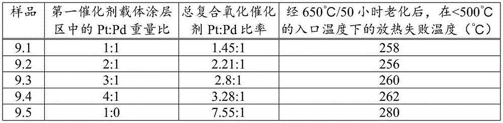
According to the present invention, the first catalyst washcoat region comprises both platinum (Pt) and palladium (Pd), with a platinum to palladium weight ratio ≧ 1. While it is generally desirable to reduce the amount of palladium in the composite oxidation catalyst relative to platinum to reduce the overall cost of the platinum group metal in the catalyst, as can be seen from sample 9.5 in example 9 below, applicants' experimental data indicates that it is undesirable to completely remove palladium from the first catalyst washcoat zone without adversely affecting the exotherm generation function upon catalyst aging. In this regard, sample 9.5 in example 9 shows that where the underlying washcoat layer having a Pt: Pd weight ratio of 2:1 is impregnated with an impregnation medium that does not contain palladium (i.e., a Pt: Pd weight ratio of 1:0) to form a first catalyst washcoat zone having a Pt: Pd weight ratio of approximately 47:1, the resulting catalyst's ability to promote an exotherm is compromised, i.e., the first catalyst washcoat zone is less stable to aging. However, although less preferred, sample 9.5 in example 9 is still an effective composite oxidation catalyst for the purposes of the present invention.
However, it is generally preferred that the weight ratio of platinum (Pt) to palladium (Pd) in the first catalyst washcoat zone is 10:1 ≧ 1:1, preferably 10:1 ≧ 1.5:1 or 6:1 ≧ 1.5:1, more preferably 4:1 ≧ 1.5:1, such as 6:1 ≧ 2:1, 4:1 ≧ 1.5:1 or 2:1 ≧ 1:1, since example 9 also demonstrates that the exotherm failure temperature (deg.C) test at an inlet temperature of <500 deg.C is similar for aged composite oxidation catalysts having a first catalyst washcoat zone obtained by impregnating the underlying catalyst washcoat layer having a Pt: Pd weight ratio of 1:1, 2:1, 3:1, and 4: 1. It has also been found that the Pt: Pd ≧ 1:1 weight ratio feature, in combination with the alkaline earth metal component, improves the exothermic light-off temperature (light-off temperature reduction), allowing for increased exothermic generation from lower exhaust gas temperatures in both active and active-passive regeneration systems.
It will be appreciated that further reductions in total platinum group metal costs (since the current cost by weight of palladium is significantly greater than the current cost by weight of platinum) in a composite oxidation catalyst according to the present invention for equivalent function may be achieved where the first catalyst washcoat zone comprises a higher weight ratio of Pt to Pd (e.g., ≧ 1.5:1, such as the preferred 10:1 ≧ 1.5:1 range, or ≧ 2:1 in combination with an outlet zone (e.g., a third catalyst washcoat zone) defined at one end by the outlet end of a composite oxidation catalyst substrate comprising a preformed, manganese-doped, mixed magnesium aluminum metal oxide. A composite oxidation catalyst having an outlet zone comprising the composition has been shown in example 8 to improve exothermic performance and may enable the use of lower amounts of platinum group metals in the outlet zone or in a second catalyst washcoat layer that partially forms the outlet (third catalyst washcoat) zone.
Preferably, particularly in embodiments including three or more catalyst washcoat zones, the one or more platinum group metals in the second catalyst washcoat zone comprise both platinum and palladium. In particularly preferred features, the mass ratio of platinum to palladium in the second catalyst washcoat zone is greater than the mass ratio of platinum to palladium in the first catalyst washcoat zone. This Pt to Pd mass ratio in the second catalyst washcoat zone, in combination with the platinum group metal loading in the second catalyst washcoat zone, has the advantage that the catalyst has improved hydrocarbon slip control, CO oxidation and NO oxidation.
In this regard, in embodiments consisting of two zones, for example, as shown in FIG. 1-to allow for any overlap with the production process (see "definitions" section below) -preferably the second catalyst washcoat zone comprises a Pt-rich PGM composition comprising palladium, preferably in a weight ratio of ≧ 10:1, ≧ 5:1, ≧ 3:1 or ≧ 2: 1. This feature has been found to be advantageous in combination with a first catalyst washcoat zone having Pt: Pd ≧ 1:1, since a second catalyst washcoat zone of pure Pt (i.e., a Pt: Pd weight ratio of 1:0) has been found to be detrimental to exothermic light-off and HC slip in the aged catalyst. In this regard, the presence of Pd in addition to Pt in the second catalyst washcoat zone may improve the aging stability of the second catalyst washcoat zone, i.e., maintain oxidation activity through aging. However, in combination with manganese, a Pt to Pd weight ratio of 1:0 in the second catalyst washcoat zone has been found to favor NO oxidation (see example 8 and below).
In a composite oxidation catalyst according to the present invention that includes three catalyst washcoat zones, the mass ratio of platinum to palladium preferably increases from the first catalyst washcoat zone to the second catalyst washcoat zone to the third catalyst washcoat zone. This may be achieved, for example, in the embodiments shown in fig. 2 and 4, where the second catalyst washcoat (7) has a higher Pt to Pd mass ratio than the first catalyst washcoat, preferably a mass ratio of 1:0, i.e. only Pt and substantially no Pd, such that the monolayer second catalyst washcoat in the third catalyst washcoat zone (3) has the highest Pt to Pd ratio of any catalyst washcoat zone disposed on the substrate. However, the same comments apply in connection with a composite oxidation catalyst that includes only two catalyst washcoat zones, i.e., the aging stability of the third catalyst washcoat zone can be improved by including some palladium (e.g., ≧ 10:1, ≧ 5:1, ≧ 3:1 or ≧ 2:1) while still maintaining the preferred arrangement of increasing platinum to palladium mass ratios from the first catalyst washcoat zone to the second catalyst washcoat zone and then to the third catalyst washcoat zone. In the context of a three-zone composite oxidation catalyst, the benefit of also including manganese in the third catalyst washcoat zone (3) is also mentioned (see example 8 and below).
Further, in a composite oxidation catalyst having four catalyst washcoat zones, the mass ratio of platinum to palladium in each successive catalyst washcoat zone arranged in series along the length L of the substrate at the inlet end after the first catalyst washcoat zone is greater than the mass ratio of platinum to palladium in the immediately preceding catalyst washcoat zone. This may again be achieved, for example, in the embodiments shown in fig. 3 and 5, where the second catalyst washcoat (7) has a higher Pt to Pd mass ratio than the first catalyst washcoat, preferably a mass ratio of 1:0, i.e. only Pt and substantially no Pd, such that the second catalyst washcoat of a single layer in the third catalyst washcoat zone (3) has the highest Pt to Pd ratio of any catalyst washcoat zone. However, the same comments apply in connection with a composite oxidation catalyst that includes only two catalyst washcoat zones, i.e., the aging stability of the third catalyst washcoat zone can be improved by including some palladium (e.g., ≧ 10:1, ≧ 5:1, ≧ 3:1 or ≧ 2:1) while still maintaining the preferred arrangement of increasing platinum to palladium mass ratios from the first catalyst washcoat zone to the second catalyst washcoat zone and then to the third catalyst washcoat zone. In the context of a four-zone composite oxidation catalyst, the benefit of also including manganese in the third catalyst washcoat zone (3) is also mentioned (see example 8 and below).
It should be understood that-in the context of a four-zone composite oxidation catalyst according to the present invention- "the features in each successive catalyst washcoat zone arranged in series along the length L of the substrate at the inlet end after the first catalyst washcoat zone are greater than the features in the immediately preceding catalyst washcoat zone" is a different order of numbering of the catalyst washcoat zones from that in fig. 3 and 5. That is, in fig. 3 and 5, the washcoat catalyst zone numbering sequence from the first catalyst washcoat zone (1) is 1 → 2 → 4 → 3. This is because the third catalyst washcoat zone (3) is defined at the second end by the second substrate end (or outlet end). However, "the characteristic in each successive catalyst washcoat zone arranged in series along the substrate length L at the inlet end after the first catalyst washcoat zone is greater than the characteristic in the immediately preceding catalyst washcoat zone" requires, for example, that the mass ratio of Pt: Pd in the fourth catalyst washcoat zone is greater than the mass ratio of Pt: Pd in the immediately preceding second catalyst washcoat zone (2), and that the mass ratio of Pt: Pd in the third catalyst washcoat zone (3) is greater than the mass ratio of Pt: Pd in the immediately preceding fourth catalyst washcoat zone (4).
Preferably, the one or more platinum group metals in the second catalyst washcoat zone comprise both platinum and palladium, wherein the mass ratio of platinum to palladium is >1:1, preferably 10:1>3:2, such as 5:1>3: 2.
Typically, the first catalyst washcoat zone or the first catalyst washcoat layer does not comprise rhodium.
It may be preferred that the second catalyst washcoat zone or the second catalyst washcoat layer does not contain rhodium.
The third catalyst washcoat region or the fourth catalyst washcoat region may not include rhodium.
It may also be preferred that the composite oxidation catalyst according to the present invention is substantially completely free of rhodium.
The inventors have also found that there may be an advantage in improving the generation of exotherms in the case where the one or more platinum group metal components and/or the one or more first alkaline earth metal components are not uniformly distributed in a direction perpendicular to the substrate surface. This will be discussed in more detail under the following headings.
Alkaline earth metal component
It will be appreciated that the alkaline earth metal in the composite oxidation catalyst according to the present invention is not intended to store NOxFor later passage of said lean NOxThe catalytic process is released and reduced. This is what is called lean NO for specially designed catalystsxFor the purpose of a trap (LNT), the catalyst may also include alkaline earth metals, platinum group metals, and optionally ceria, doped ceria or ceria mixed oxide components, but the LNT must be used in conjunction with a specially programmed engine control unit. The engine is controlled to have NO thereinxLean stoichiometric operating mode absorbed on the LNT and rich exhaust pulses with additional reducing species (such as CO and/or hydrocarbons) contained therein are contacted with the LNT to desorb the absorbed NOxAnd by the depletion of NO on platinum group metalsxThe catalytic reaction reduces it to a reduced operating mode. In the use of the LNT, the frequency of lean/rich cycles is approximately 60 seconds lean and 5 seconds rich. Desulfation of the LNT is less frequent but the enrichment period may be longer. However, control of the desulfation event also requires a specially programmed engine control unit.
The composite oxidation catalyst of the present invention can be distinguished from an LNT in at least two important respects. First, LNTs are not used to treat exhaust gas from heavy duty diesel engines, which uses SCR catalysts. This is primarily because LNT catalysts for heavy diesel vehicles would need to be so large that the cost of the required platinum group metals would make the cost of the catalyst prohibitive. Second, preferably, the composite oxidation catalyst of the present invention is substantially free of ceria, doped ceria or ceria mixed oxide or composite oxide components.
In accordance with a first inventive aspect, the first catalyst washcoat region comprises one or more first alkaline earth metal components supported on a first refractory metal oxide support material. The inventors have discovered that the presence of an alkaline earth metal component (preferably comprising barium) improves HC conversion for the purpose of generating an exotherm from a hydrocarbon fuel to such an extent that the amount of platinum group metal(s) in the first catalyst washcoat zone can be reduced by about 7g/ft3And still have the same activity. It is believed that the relatively high platinum group metal loading in the first catalyst washcoat zone rapidly initiates and accelerates the exothermic reaction, while the presence of one or more alkaline earth metals stabilizes the PGM, for example, by reducing sintering and improving thermal durability.
The one or more alkaline earth metal components in the first catalyst washcoat region are preferably barium (Ba) or strontium (Sr), preferably Ba, e.g., the one or more first alkaline earth metal components in the first catalyst washcoat region consist of barium.
The reason why barium is preferred over other alkaline earth metals is explained below under the heading "uneven distribution of alkaline earth metal components and/or platinum group metal components in the washcoat".
The total alkaline earth metal component loading in the first catalyst washcoat zone may be 10-100g/ft calculated as elemental metal3Preferably 20-80g/ft3. Too much alkaline earth metal component may be detrimental to the exotherm. In this regard, the ratio of the total mass of the alkaline earth metal component to the total mass of the Platinum Group Metal (PGM) component may be 1:1 to 1:2, preferably 1:1 to 50: 80.
According to the method of the sixth inventive aspect, the one or more first alkaline earth metal components may be present in the catalyst washcoat applied in step (a) and/or in the impregnation solution of step (b), but are preferably present in the catalyst washcoat of step (a) of the sixth inventive aspect (e.g., the first catalyst washcoat). This is because, in the case where alkaline earth metal (e.g., barium) salts are present in the impregnation medium of step (b), controlling the use of platinum group metal salts in the impregnation medium using the preferred pH range may make it more difficult to control them, and thus many of the alkaline earth metal salts migrate out of the targeted first catalyst washcoat zone by wicking. This alternative is preferred because the location of the final alkaline earth metal in the finished product can be better controlled, with the alkaline earth metal component being present in the washcoat and then dried and calcined after coating.
It will be appreciated that where the catalyst washcoat layer comprising one or more alkaline earth metals (e.g. the first catalyst washcoat layer) is applied in step (a) of the sixth inventive aspect and the catalyst washcoat layer itself is impregnated with a solution comprising one or more alkaline earth metal components in step (b) of the sixth inventive aspect, the composition of the resulting impregnation zone is a combination of the content of the alkaline earth metal components in the underlying catalyst washcoat layer and the impregnation solution.
The second catalyst washcoat region may also comprise one or more alkaline earth metal components, preferably comprising barium. This may be derived from one or more first alkaline earth metal components (preferably barium) present in the catalyst washcoat (e.g., first catalyst washcoat) of the sixth inventive aspect of step (a), or wherein the composite oxidation catalyst comprises a third or fourth catalyst washcoat region, a second catalyst washcoat. The one or more alkaline earth metal components present in the second catalyst washcoat layer may be referred to herein as one or more second alkaline earth metal components. The third and fourth catalyst washcoat layers may also comprise one or more second alkaline earth metal components, preferably barium.
The inventors have also found that there may be an advantage in improving the exothermic generation at least from the first catalyst coating region in the case where the one or more platinum group metal components and/or the one or more first alkaline earth metal components are not uniformly distributed in a direction perpendicular to the substrate surface. This will be discussed in more detail under the following headings.
Refractory metal oxide support material
The first, second, third or fourth refractory metal oxide support material of the first and/or second catalyst washcoat layer is each typically selected from the group consisting of alumina, magnesia, silica, zirconia, titania, ceria and composite or mixed oxides of two or more thereof. In principle, any suitable refractory metal oxide support material may be used as the first refractory metal oxide support material. Each of the first, second, third or fourth refractory metal oxide support materials of the first or second catalyst washcoat layers or the support materials of the refractory metal oxide support materials may be the same as or different from each other. However, it should be understood that the composite oxidation catalyst illustrated in FIG. 1 may be impregnated at a first end to an axial length L1In the case of a single washcoat layer of length L defining first (1) and second (2) catalyst washcoat regions, the refractory metal oxide support material in the first and second catalyst washcoat regions will be the same.
Furthermore, in the embodiments shown in fig. 2-5 that include three and four catalyst washcoat zones, if the refractory metal oxide support material used in the first catalyst washcoat layer (6) is an "X", then since the first, second, and (if present) fourth catalyst washcoat zones comprise only the entire length L of the first catalyst washcoat layer (6)3Each of the first, second and, if present, fourth catalyst washcoat regions will each comprise a refractory metal oxide support material "X", i.e., the first, second and, if present, fourth refractory metal oxide support materials will be the same. Similarly, where the second catalyst washcoat layer (7) in the embodiments shown in fig. 2-5 comprises a refractory metal oxide support material "Y", the third catalyst washcoat region and, if present, includes an overlapThe second or fourth catalyst washcoat zone of a zone comprises only the entire length L of the second catalyst washcoat (7)4And thus each of these regions will comprise refractory metal oxide support material "Y".
Preferably, the refractory metal oxide support material is selected from the group consisting of alumina, silica, zirconia, ceria and composite or mixed oxides of two or more thereof, most preferably from the group consisting of alumina, silica and zirconia and composite or mixed oxides of two or more thereof. Mixed or composite oxides include silica-alumina and ceria-zirconia, most preferably silica-alumina. Preferably, the refractory metal oxide support material does not comprise ceria or a mixed oxide or a composite oxide comprising ceria. More preferably, the refractory oxide is selected from the group consisting of alumina, silica and silica-alumina. The refractory oxide may be alumina. The refractory oxide may be silicon dioxide. The refractory oxide may be silica-alumina.
Because the first catalyst washcoat region comprises one or more first alkaline earth metal components supported on a first refractory metal oxide support material, preferably the first refractory metal oxide support material of the first catalyst washcoat region or an underlying catalyst washcoat layer (e.g., the first catalyst washcoat layer) comprises or consists essentially of alumina doped with a heteroatom component. The heteroatom component typically comprises silicon, manganese (see below), magnesium, barium, lanthanum, cerium, titanium or zirconium or a combination of two or more thereof. The heteroatom component may comprise, consist essentially of, or consist of: silicon oxide, manganese oxide, magnesium oxide, barium oxide, lanthanum oxide, cerium oxide, titanium oxide, or zirconium oxide. More preferably, the alumina doped with the heteroatom component is alumina doped with silica or alumina doped with magnesia or alumina doped with manganese oxide. Even more preferably, the alumina doped with the heteroatom component is alumina doped with silica. The alumina doped with the heteroatom component may be prepared using methods known in the art or, for example, by the method described in US 5,045,519.
Inclusion of the dopant may stabilize the refractory metal oxide support material or promote catalytic reactions of the supported platinum group metal. Typically, the dopant may be selected from zirconium (Zr), titanium (Ti), silicon (Si), yttrium (Y), lanthanum (La), praseodymium (Pr), samarium (Sm), neodymium (Nd), barium (Ba), and oxides thereof. Generally, the dopant is different from the refractory metal oxide (i.e., the cation of the refractory metal oxide). Thus, for example, when the refractory metal oxide is titania, then the dopant is not titanium or an oxide thereof.
When the refractory metal oxide support material is doped with a dopant, then typically the refractory metal oxide support material comprises a total amount of dopant of from 0.1 wt.% to 10 wt.%. The total amount of dopants is preferably 0.25 to 7 wt%, more preferably 2.5 to 6.0 wt%. Preferably, the dopant is silica, as oxidation catalysts comprising such support materials in combination with platinum group metals and alkaline earth metals promote oxidation reactions, such as CO and hydrocarbon oxidation.
When the refractory metal oxide support material is silica-alumina, then typically the refractory oxide consists essentially of: 20 to 95 wt% alumina and 5 to 80 wt% silica (e.g., 50 to 95 wt% alumina and 5 to 50 wt% silica), preferably 35 to 80 wt% alumina and 20 to 65 wt% silica (e.g., 55 to 80 wt% alumina and 20 to 45 wt% silica), even more preferably 45 to 75 wt% alumina and 25 to 55 wt% silica. Silica-alumina having a higher silica content (e.g., a silica content of about 30 wt.%) can provide greater sulfur tolerance to the composite oxidation catalyst as a whole.
When the refractory oxide is a ceria-zirconia, typically the ceria-zirconia consists essentially of: 20 to 95 wt% ceria and 5 to 80 wt% zirconia (e.g., 50 to 95 wt% ceria and 5 to 50 wt% zirconia), preferably 35 to 80 wt% ceria and 20 to 65 wt% zirconia (e.g., 55 to 80 wt% ceria and 20 to 45 wt% zirconia), even more preferably 45 to 75 wt% ceria and 25 to 55 wt% zirconia.
Typically, the first and second catalyst washcoat layers comprise 0.1 to 3.5g in-3(e.g., 0.25 to 3.0g in-3) Preferably 0.3 to 2.5g in-3And still more preferably 0.5 to 2.0g in-3And even more preferably 0.6 to 1.75g in-3(e.g., 0.75 to 1.5g in-3) Of a refractory metal oxide support material.
Generally, the refractory metal oxide support materials used in the present invention are in particulate form. The first support material may have a D of 50 μm or less, preferably 30 μm or less, and more preferably 20 μm or less90Particle size (as determined by conventional laser diffraction techniques). The particle size distribution of the refractory metal oxide support material is selected to facilitate adhesion to the substrate. The particles are typically obtained by grinding.
Additionally, each of the first, second, third or fourth refractory metal oxide support materials of the first or second catalyst washcoat layer or the or each support material of the refractory metal oxide support materials may or may not comprise or consist essentially of a hydrocarbon adsorber. The hydrocarbon adsorbent may be selected from zeolites, activated carbon, porous graphite, and combinations of two or more thereof. If present, it is preferred that the hydrocarbon adsorbent is a zeolite, most preferably an aluminosilicate zeolite.
When the support material comprises a hydrocarbon adsorbent, then typically the total amount of hydrocarbon adsorbent is from 0.05 to 3.00g in-3In particular 0.10 to 2.00g in-3(e.g., 0.2 to 0.8g in-3)。
When the hydrocarbon adsorbent is a zeolite, then preferably each zeolite is a medium pore zeolite (e.g., a zeolite having a maximum ring size of ten tetrahedral atoms) or a large pore zeolite (e.g., a zeolite having a maximum ring size of twelve tetrahedral atoms).
Examples of suitable zeolites or zeolite types include Faujasite (FAU), clinoptilolite, mordenite, silicalite (MFI), ferrierite, zeolite X (FAU), zeolite Y (FAU), ultrastable zeolite Y (FAU), AEI zeolite, ZSM-5 zeolite, ZSM-12 zeolite (MTW), ZSM-20 zeolite, ZSM-34 zeolite, CHA zeolite, SSZ-13 zeolite, SAPO-5 zeolite (AFI), offretite, beta zeolite, or copper CHA zeolite. The zeolite, if present, is preferably ZSM-5 (medium pore zeolite), beta zeolite (large pore zeolite) or Y zeolite (large pore zeolite). If present, Y zeolite or beta zeolite is preferred, with beta zeolite being most preferred.
However, according to the present invention, it is preferred that the oxidation catalyst (excluding any phosphorus and/or zinc guard bed, for an explanation of its characteristics, see below) does not comprise a hydrocarbon adsorbent at all, in particular a zeolite, as zeolites can undergo hydrothermal degradation during an exothermic generation event, making their addition less desirable. The inclusion of a hydrocarbon adsorbent in the oxidation catalyst for heavy duty vehicles is also less necessary because the exhaust gas temperature emitted from heavy duty diesel engines rarely fluctuates in use below the temperature at which hydrocarbon adsorption is desired to improve overall cycle hydrocarbon conversion.
Length of catalyst support coating zone
In embodiments including only two catalyst washcoat zones, such as shown in fig. 1, the length of the first catalyst washcoat zone may be < 50%, preferably 20% to 40%, of the total substrate length.
However, in embodiments including three or four catalyst washcoat zones (e.g., those shown in any of fig. 2-5), the length of the first washcoat zone may be 15% to 35% of the total substrate length (L).
In embodiments including three or four catalyst washcoat zones (e.g., those shown in any of fig. 2-5), the length of the overlap region of the first and second catalyst washcoat layers (6, 7), i.e., the length of the second catalyst washcoat zone in fig. 2 and 4 or the length of the fourth catalyst washcoat zone in fig. 3 and 5, may be 10% to 40%, preferably 10% to 30%, of the total substrate length (L).
In embodiments including three or four catalyst washcoat zones (e.g., those shown in any of fig. 2-5), the length of the third catalyst washcoat zone may be 10% to 40% of the total substrate length (L), more preferably 15% to 35%, such as 20% to 30% of the total substrate length (L).
In embodiments including four catalyst washcoat zones (e.g., those shown in fig. 3 and 5), the second catalyst washcoat zone in fig. 3 and 5 may be 1% to 40%, preferably 5% to 30%, of the total substrate length (L).
In a particularly preferred embodiment, the inlet catalyst washcoat 6 is first coated on the substrate to a length of about 80% L, and then the outlet catalyst washcoat 7 is coated on the substrate to a length of about 50% L, i.e. overlapping the catalyst washcoat 6 by 30% L. The length of the first washcoat region may be 15% to 35% of the total substrate length (L).
Since the substrate length can vary, it is generally more useful to refer to the lengths of the first, second, and, if present, third and fourth catalyst washcoat zones by their axial lengths (i.e., as a percentage or fraction) relative to the total axial substrate length. Generally, the length of the substrate applied to the present invention is 3 to 6 inches (including 3 and 6 inches), more typically 4 to 6 inches. Thus, the washcoat length or washcoat zone length may be referred to by reference to a percent zone length x total substrate length (L).
Inhomogeneous distribution of alkaline earth metal components and/or platinum group metal components in the washcoat
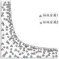
This aspect is illustrated in fig. 6 and 7 and is described briefly in the description of the figures above.
In the first inventive aspect, the first catalyst washcoat zone may have a non-uniform distribution of one or more platinum group metal components and/or one or more first alkaline earth metal components in a direction perpendicular to the substrate surface, as determined by Electron Probe Microscopy Analysis (EPMA), wherein the concentration of the one or more platinum group metal components and/or first alkaline earth metal components decreases in the perpendicular direction toward the substrate surface, as determined by EPMA.
It has been found that a non-uniform vertical distribution of one or more platinum group metal components and/or one or more first alkaline earth metal components can be achieved within a single layer. Thus, the benefits associated with stratification can be achieved by using a single layer or fewer layers to achieve non-uniform vertical distribution of these components through the catalyst layer.
In the composite oxidation catalysts of the present invention, the first catalyst washcoat region may have a non-uniform distribution of one or more platinum group metal components and/or one or more first alkaline earth metal components in a direction perpendicular to the substrate surface, optionally present in a single layer, e.g., a catalyst washcoat such as a first catalyst washcoat (i.e., the catalyst layer does not include multiple layers).
Preferably, the catalyst washcoat has a non-uniform distribution of one or more platinum group metal components and/or one or more alkaline earth metal components throughout its thickness (i.e., the direction perpendicular to the substrate surface represents the thickness of the catalyst layer), most preferably a non-uniform distribution of both one or more platinum group metal components and one or more alkaline earth metal components.
Typically, the catalyst washcoat has a first surface and a second surface. Generally, the first surface is parallel (e.g., substantially parallel) to the second surface (i.e., the plane containing the first surface is parallel to the plane containing the second surface). The first surface and the second surface are generally parallel to a surface of the substrate. Thus, the direction perpendicular to the substrate surface is also perpendicular to the first surface and/or the second surface.
The perpendicular distance between the first surface and the second surface is typically the thickness of the catalyst washcoat.
The first surface may be an exposed surface of the catalyst layer, or an additional layer (e.g., a second layer) may be disposed on or supported on the first surface. The first surface is typically on the upper side of the catalyst layer (i.e. it is the top surface). By exposed, it is meant that the first surface is not completely or substantially covered by another material and that the exhaust gas that normally passes through the catalyst is in contact with the first surface before the second surface.
The second surface is not an exposed surface of the catalyst washcoat. Generally, the second surface is in direct contact with a surface of the substrate and/or a surface of another layer. Thus, the second surface is typically the underside of the catalyst washcoat (i.e., it is the bottom or lowest surface).
Preferably, the amount of the one or more platinum group metal components and/or the one or more first alkaline earth metal components decreases in a vertical direction towards the surface of the substrate (i.e., the amount of the one or more platinum group metal components and/or the one or more first alkaline earth metal components decreases from the first surface to the second surface). The amount of the one or more platinum group metal components and/or the one or more first alkaline earth metal components may decrease continuously or discontinuously, preferably continuously, in the vertical direction towards the substrate surface. Thus, when, for example, the first catalyst washcoat region comprises a single layer (which is a catalyst washcoat), then the amount of the one or more platinum group metal components and/or the one or more first alkaline earth metal components decreases from the exposed surface of the catalyst washcoat toward the surface of the substrate.
The catalyst washcoat may have a linear or non-linear rate of decrease in the amount of the one or more platinum group metal components and/or the one or more first alkaline earth metal components in the vertical direction toward the surface of the substrate (i.e., a linear or non-linear rate of decrease in the amount of the first platinum group metal in the vertical direction from the first surface to the second surface).
Typically, at least 60% of the total amount of the one or more platinum group metal components and/or the one or more first alkaline earth metal components (e.g., the one or more platinum group metal components and/or the one or more first alkaline earth metal components of the catalyst washcoat) may be distributed between the first surface and a point or plane in the catalyst washcoat that is intermediate the first surface and the second surface (e.g., at 50% of the vertical distance between the first surface and the second surface). The plane is generally parallel to the first surface. Reference to "intermediate" in this context generally refers to the average intermediate distance between the first surface and the second surface. Preferably, at least 70%, more preferably at least 75% (such as at least 80%), still more preferably at least 90% of the total amount of the one or more platinum group metal components and/or the one or more first alkaline earth metal components (e.g., the one or more platinum group metal components and/or the one or more first alkaline earth metal components of the catalyst washcoat) may be distributed between the first surface and a point or plane in the catalyst washcoat that is intermediate the first surface and the second surface.
Generally, at least 60% of the total amount of the one or more platinum group metal components and/or the one or more first alkaline earth metal components (e.g., the one or more platinum group metal components and/or the one or more first alkaline earth metal components of the catalyst washcoat) can be distributed between the first surface and a point or plane at 25% of the perpendicular distance in the catalyst washcoat from the first surface to the second surface. The plane is generally parallel to the first surface. Preferably, at least 70%, more preferably at least 75% (such as at least 80%), and still more preferably at least 90% of the total amount of the one or more platinum group metal components and/or the one or more first alkaline earth metal components (e.g., the one or more platinum group metal components and/or the one or more first alkaline earth metal components of the catalyst washcoat) may be distributed between the first surface and a point or plane in the catalyst washcoat that is located at 25% of the perpendicular distance from the first surface to the second surface.
At least 60% of the total amount of the one or more platinum group metal components and/or the one or more first alkaline earth metal components (e.g., the one or more platinum group metal components and/or the one or more first alkaline earth metal components of the catalyst washcoat) may be distributed between the first surface and a point or plane at 10% of the perpendicular distance in the catalyst washcoat from the first surface to the second surface. The plane is generally parallel to the first surface. Preferably, at least 70%, more preferably at least 75% (such as at least 80%), and still more preferably at least 90% of the total amount of the one or more platinum group metal components and/or the one or more first alkaline earth metal components (e.g., the one or more platinum group metal components and/or the one or more first alkaline earth metal components of the catalyst washcoat) may be distributed between the first surface and a point or plane in the catalyst washcoat that is located at 10% of the perpendicular distance from the first surface to the second surface.
Generally, the non-uniform distribution of the first platinum group metal in the direction perpendicular to the surface of the substrate can be a graded distribution of the one or more platinum group metal components and/or the one or more first alkaline earth metal components. Alternatively, the non-uniform distribution of the first platinum group metal in the direction perpendicular to the substrate surface may be a stepped distribution of the one or more platinum group metal components and/or the one or more first alkaline earth metal components.
The catalyst washcoat may have a uniform horizontal distribution or a non-uniform horizontal distribution of one or more platinum group metal components and/or one or more first alkaline earth metal components.
Typically, the distribution of the one or more platinum group metal components and/or the one or more first alkaline earth metal components is uniform or non-uniform in a direction parallel to the surface of the substrate (i.e., the longitudinal plane) and in a direction perpendicular to the central longitudinal axis of the substrate (i.e., in a direction parallel to the inlet end face and/or the outlet end face of the substrate). Preferably, the distribution of the first platinum group metal is uniform in a direction parallel to the surface of the substrate and perpendicular to the central longitudinal axis of the substrate.
Generally, the distribution of the one or more platinum group metal components and/or the one or more first alkaline earth metal components in a direction parallel to the surface of the substrate (i.e., the longitudinal plane) and a direction parallel to the central longitudinal axis of the substrate (i.e., a direction perpendicular to the inlet and/or outlet end faces of the substrate) can be uniform or non-uniform. Preferably, the distribution of the one or more platinum group metal components and/or the one or more first alkaline earth metal components is uniform in a direction parallel to the surface of the substrate and parallel to the central longitudinal axis of the substrate.
The method of obtaining a non-uniform distribution of one or more platinum group metal components and/or one or more first alkaline earth metal components in the first catalyst washcoat zone in a direction normal to the substrate surface is: conventional thermal drying of a solute salt of one or more platinum group metal components impregnated into a washcoat comprising one or more platinum group metals and a first refractory metal oxide support material, wherein the one or more first alkaline earth metal components are present in the washcoat and/or are present as a solute salt in an impregnation medium with the solute salt of the one or more platinum group metal components. Preferably, the first alkaline earth metal component is present in a washcoat having one or more platinum group metal components impregnated thereon. Impregnation is a common general knowledge technique, as discussed, for example, in Heck et al, chapter 2.3, "Catalytic Air Pollution Control-Commercial Technology", third edition (2009), John Wiley & Sons, inc. The reference section also discusses thermal drying and calcination. The inventors have found that an alternative drying method, i.e. freeze-drying, which forms well-dispersed alkaline earth metal particles in a direction perpendicular to the substrate surface (see e.g. WO 2009/080155) results in a less useful exotherm. Further explanation can be found below under the heading "preparation method".
Preferably the alkaline earth metal is barium. We have found that when a non-barium alkaline earth metal is used (for example as its acetate), the non-barium alkaline earth metal salt is less mobile in the drying step and therefore tends not to form a non-uniform distribution as alkaline earth metal salts such as strontium, calcium or magnesium. Applicants believe that the presence of platinum group metals (particularly palladium and barium) at the upper surface of the catalyst washcoat (e.g., in a so-called "shell") is beneficial to the exotherm generating function which is the primary object of the composite oxidation catalyst of the present invention. Therefore, it is preferred that in addition to the uneven distribution of the barium component in the direction perpendicular to the substrate surface as determined by EPMA, wherein if the barium component concentration decreases in the perpendicular direction toward the substrate surface, the palladium concentration also decreases in the perpendicular direction toward the substrate surface.
Phosphorus and/or zinc guard bed
As explained in the introduction to the present description, lubricants for heavy vehicles have a relatively high content of additives comprising zinc and/or phosphorus. Thus, when used, the catalyst in the exhaust system of heavy vehicles is exposed to relatively large amounts of zinc and/or phosphorus compounds over the lifetime of the vehicle in use. Applicants' inventors analyzed an oxidation catalyst, which is the first catalytic substrate disposed in the exhaust system downstream of the vehicular european 6 heavy duty diesel engine at the end of vehicle life (about 100 kilometres), and found that there was 1.0 to 1.5 wt% phosphorus on the oxidation catalyst in the first quarter of the coated substrate measured from the inlet end of the substrate.
In the present invention, the first catalyst washcoat zone has the highest loading of platinum group metal on the substrate and is present in a zone defined at the first substrate end corresponding to the inlet end in use. According to the present invention, the highest loading of platinum group metal in the platinum-rich combination of platinum and palladium is a key feature of the composite oxidation catalyst for generating an exotherm from the increased amount of hydrocarbon present in the exhaust gas. Thus, poisoning of the exhaust gas entering the inlet end of the composite oxidation catalyst by the presence of the catalyst may have a disproportionate effect on the activity of the catalyst in reducing the exotherm generated by the hydrocarbon by the catalyst as follows: additional hydrocarbons are required to achieve the desired exothermic temperature, thereby indirectly reducing vehicle fuel economy; and/or increasing the hydrocarbon light-off temperature, i.e., the temperature at which the catalyst is active to begin oxidizing hydrocarbons and thus generating an exotherm relative to an oxidation catalyst uniformly coated with the same washcoat composition (see also examples 4, 5, and 6, below). Thus, hydrocarbons introduced into the exhaust at relatively low temperatures that would normally be expected to produce a particular exotherm may result in lower exotherms and increased hydrocarbon slip, resulting in higher hydrocarbon emissions into the atmosphere and/or hydrocarbon contamination of downstream exhaust system components or processes and/or on-board diagnostic (OBD) failure modes.
Applicants' inventors have investigated methods to reduce or prevent the poisoning effect of phosphorus and/or zinc compounds on the function of a composite oxidation catalyst and have found that by disposing a washcoat as an overlayer on a first catalyst washcoat region at a sufficient loading (related to washcoat thickness), optionally wherein the washcoat comprises particulate metal oxide of sufficient mean pore diameter and/or the resulting washcoat has sufficient mean inter-particle pore size, phosphorus and/or zinc compounds can be prevented or reduced from contacting the underlying first catalyst washcoat region and maintaining a higher proportion of fresh catalyst activity while the catalyst is in use than a catalyst without such additional features, while maintaining mass transfer channels of exhaust gas to the underlying first catalyst washcoat region.
Thus, in a preferred arrangement, the composite oxidation catalyst according to the first aspect of the invention comprises a washcoat overlayer extending axially from the first substrate end for protecting at least a portion of the underlying first catalyst washcoat zone from phosphorus and/or zinc poisoning in use, the washcoat overlayer comprising ≧ 0.8g/in3The particulate metal oxide loading.
Applicants' research has found that the depth of the washcoat layer appears to be important to achieve the desired function as a guard bed for phosphorus and/or zinc compounds, as 0.5g/in was found3Does not resemble 1.0g/in of relatively low loading of washcoat cap layer3The washcoat loading of (c) was as effective (see examples 4, 5 and 6, below).
The washcoat overcoat layer can consist essentially of particulate metal oxide, wherein the washcoat overcoat layer can contain certain binders or additives for auxiliary processing (e.g., powder flow), washcoat rheology modifiers, and the like. That is, while catalyst components (such as barium or one or more platinum group metals) may wick or migrate from the bottom layer into the washcoat during manufacture of the composite oxidation catalyst, the particulate metal oxide is coated, for example, in a washcoat that does not contain such metals, and such metals should not enter the washcoat overlayer. In this context, the term "consisting essentially of" as used above is intended to encompass end products in which any such metal undesirably migrates into the washcoat overlayer.
Typically, the washcoat overcoat layer has 0.8 to 3.5g in-3Preferably 0.9 to 2.5g in-3And further onPreferably 1.0 to 2.0g in-3Such as 1.1 to 1.75g in-3The particulate metal oxide loading.
Preferably, the washcoat cover layer is applied directly to the washcoat in the first catalyst washcoat zone. However, it is also within the scope of the present invention for one or more washcoat layers to be present between the preferably disposed first catalyst washcoat zone and the washcoat cover layer.
It should be understood that the application of the guard bed feature is generally applicable to all embodiments of the present invention and thus can be readily combined with each embodiment of the present invention, as specifically shown in the embodiments disclosed in fig. 1-5, as shown by the optional dashed line feature "G".
The washcoat overcoat layer may include one or more of the following additional optional features:
(a) the particulate metal oxide in the washcoat layer has an average pore size of greater than or equal to 10nm, and/or the washcoat layer has an average inter-particle pore size of greater than or equal to 10 nm;
(b) the particulate metal oxide in the washcoat coating is selected from the group consisting of alumina, silica, titania, zirconia, ceria and mixed or composite oxides or aluminosilicate zeolites of any two or more thereof. Preferably, the granular metal oxide is alumina doped with silica or alumina with an average pore diameter of more than or equal to 15 nm;
(c) the particulate metal oxide in the washcoat coating has>100m2Specific surface area per gram;
(d) the washcoat overlayer extends axially from the first substrate end up to at most 150% of the axial length of the underlying first catalyst washcoat layer to protect it from phosphorus and/or zinc poisoning when used in an exhaust system of a heavy duty diesel engine, preferably > 50% of the axial length of the underlying first catalyst washcoat zone, such as > 60%, > 70%, > 80%, > 90% or > 100% or at most 120% of its axial length; and
(e) particulate metal oxide loading in the washcoat overlayerA platinum group metal that is platinum or a combination of platinum and palladium having a Pt to Pd weight ratio ≧ 1:1, optionally wherein the platinum group metal loading in the washcoat overcoat layer is 1-35gft-3. Platinum group metals are intentionally introduced into the washcoat overlayer.
The particulate metal oxide can have one or both of an average pore size and an inter-particle pore size of ≧ 10 nm. Preferably, the average or interparticle pore size is ≥ 12nm or ≥ 15 nm. Applicants have discovered that certain parameters of the particulate metal oxide can undesirably reduce the hydrocarbon oxidation activity of the underlying first catalyst washcoat region. Thus, when applicants tested colloidal silica (Ludox)TM) As a possible particulate metal oxide for the washcoat overlayer, it was found that the porosity and permeability of the washcoat layer was insufficient to maintain the oxidation function of the underlying first catalyst washcoat layer. That is, hydrocarbon oxidation in a composite oxidation catalyst comprising colloidal silica as a particulate metal oxide is gas mass transfer limited. Although lower colloidal silica loadings can improve mass transfer, the protective effect of the washcoat overlayer is expected to be insufficient (with reference to washcoat loading limits ≧ 0.8g/in as discussed above)3). Thus, to better preserve the primary hydrocarbon oxidation function of the composite oxidation catalyst, the particulate metal oxide has an average pore size of 10nm or greater and/or the washcoat overlayer has an average inter-particle pore size of 10nm or greater.
In embodiments characterized by washcoat overlays not having supported platinum group metals, applicants' inventors have discovered that certain particulate metal oxides having relatively low average pore sizes (e.g., particulate ceria having a new average pore size of 8 nm) can be effective in the present invention. Preferably, however, the particulate metal oxide in the washcoat cover layer has an average pore size of ≧ 10nm, and/or the washcoat cover layer has an average interparticle pore size of ≧ 10nm, preferably an average pore size of ≧ 10 nm. That is, particulate metal oxides (e.g., ceria materials) having an inherently low average pore size can be employed in the present invention by appropriate particle size distribution selection (see also below) such that the average inter-particle pore size in the washcoat is ≧ 10 nm.
The average interparticle pore size of the washcoat layer can be determined by mercury intrusion.
The average pore size of the particulate metal oxide may be determined by the N-method using the Barrett-Joyner-Halenda (BJH) method2Adsorption-desorption isotherms were determined.
When the particulate metal oxide has a bimodal pore size, the requirement is satisfied in the case where at least one of the two modes is at a particle size of greater than or equal to 10 nm. For the avoidance of doubt, the preferred particulate refractory metal oxide alumina doped with silica meets at least the general definition in this paragraph.
Aluminosilicate zeolites generally do not meet the requirement of an average pore size of ≧ 10 nm. The characteristics of inter-particle pore size of ≧ 10nm can be obtained by appropriate selection of particle size (i.e., particle size distribution). As explained above in connection with colloidal silica, where the washcoat particles are too fine, the inter-particle pores are too small to sustain mass transfer of exhaust gas with the underlying first catalyst washcoat. By appropriate selection of the particle size, interparticle pores can be obtained between particles of appropriate size to satisfy the preferred condition of interparticle pore diameter of ≧ 10 nm.
For example, the particles of particulate metal oxide may have a D90 of <100 microns. The particles of the particulate metal oxide may preferably have a D90 of <75 microns, such as <50 microns (e.g., <30 microns), and more preferably <20 microns, such as <15 microns. Better filling and adhesion can be obtained when the refractory oxide has a smaller D90.
As known in the art, D90 is the particle size value at which 90% of the particles in the distribution have a particle size below this value. For the avoidance of doubt, the d90 measurement may be taken using a Malvern Mastersizer 2000TMObtained by laser diffraction particle size analysis, which is a volume-based technique (i.e., D90 may also be referred to as D)V90 (or D (v,0.90)) and applying a mathematical Mie (Mie) theoretical model to determine the particle size distribution.
Typically, the particles of particulate metal oxide have a D90 of >0.1 microns. Preferably, the particles of the particulate metal oxide have a D90 of >1.0 micron, such as >5.0 micron.
Particulate metal oxides that meet the required conditions for the protective bed washcoat overlayer in accordance with the preferred arrangement and have application in the present invention include alumina, silica, titania, zirconia, ceria and mixed or composite oxides of any two or more thereof (such as silica-doped titania, ceria-zirconia mixed oxide, preferably silica-doped alumina) or aluminosilicate zeolites. For example, the particulate metal oxide may be selected from the group consisting of alumina, ceria, silica-doped alumina, titania-alumina, zirconia-alumina, ceria-zirconia-alumina, silica-titania, silica-zirconia, zirconia-titania, ceria-zirconia, and alumina-magnesia. Preferably, the particulate metal oxide is selected from alumina, silica-doped alumina, titania-alumina, zirconia-alumina, silica-titania, silica-zirconia, zirconia-titania and alumina-magnesia, i.e. the particulate metal oxide does not comprise cerium, as discussed above.
The particulate metal oxide may optionally be doped (e.g., with a dopant). The dopant may be selected from zirconium (Zr), titanium (Ti), silicon (Si), yttrium (Y), lanthanum (La), praseodymium (Pr), samarium (Sm), neodymium (Nd), and oxides thereof. The inclusion of the dopant can thermally stabilize the particulate metal oxide. It should be understood that any reference to "doped" in this context refers to a material in which the bulk or host lattice of the particulate metal oxide is substitutionally or interstitially doped with a dopant. In some cases, a small amount of dopant may be present at the surface of the particulate metal oxide. However, most of the dopant will generally be present in the host of the particulate metal oxide.
When doping the particulate metal oxide, the total amount of dopant is from 0.5 wt.% to 15 wt.%, preferably from 1 wt.% to 10 wt.% (e.g., about 5 wt.%) of the particulate metal oxide. Preferred granular formThe metal oxide is a silica-doped refractory metal oxide alumina that can meet the requirement of an average pore diameter of greater than or equal to 10nm and can also have an average pore diameter of greater than or equal to about 120m2Specific surface area in g (see below).
In embodiments where the particulate metal oxide comprises an aluminosilicate zeolite, examples of suitable zeolites or zeolite framework types include faujasite, clinoptilolite, mordenite, silicalite, ferrierite, zeolite X, zeolite Y, ultrastable zeolite Y, AEI, ZSM-5 zeolite, ZSM-12 zeolite, ZSM-20 zeolite, ZSM-34 zeolite, CHA zeolite, SSZ-13 zeolite, offretite, beta zeolite or copper CHA zeolite. The zeolite is preferably ZSM-5, beta zeolite or Y zeolite. The aluminosilicate zeolite may include one or more base metals, such as at least one of copper, iron or manganese. For example, in the case of aluminosilicate zeolites having a CHA framework type code, CHA may be promoted with copper. Alternatively, the aluminosilicate zeolite may be intended to be free of base metals.
The particulate metal oxide can be a refractory metal oxide, which term, according to the definition used in this application, excludes aluminosilicate zeolites.
Particularly preferred particulate metal oxides for use in the present invention are alumina-doped refractory metal oxide silicas which do not contain the intended precious metals, including the platinum group metals, in the total amount of silica dopant disclosed hereinabove. Alumina with an average pore diameter of > 15nm is also preferred. Such materials are referred to herein as "wide pore alumina" and are known, for example, from EP1077769 a 1.
The specific surface area of the particulate metal oxide is also considered important because the higher the specific surface area of the particulate metal oxide component, the greater the expected capacity of the washcoat to adsorb, for example, glassy zinc phosphate compounds derived from lubricant additives.
The particles of particulate metal oxide used in the washcoat overlayer of the fresh composite oxidation catalyst according to the invention have a particle size of greater than or equal to about 100m2/g(>About 100m2/g), preferably ≥ about 120m2/g(>About 120m2/g), such as ≧ 150m2/g(>About 150m2/g) and not less than about 180m2/g(>About 180m2/g) or more than or equal to about 200m2/g(>About 200m2/g) average Specific Surface Area (SSA). Generally, the aluminosilicate zeolite has an average particle size of greater than or equal to about 200m2SA in g.
The average Specific Surface Area (SSA) of the particles of the refractory oxide can be determined by nitrogen physisorption at-196 ℃ using a volume method. The average SSA was determined using the BET adsorption isotherm equation.
In a preferred embodiment, the particulate metal oxide in the washcoat overlayer supports a platinum group metal that is platinum or a combination of platinum and palladium having a Pt to Pd weight ratio ≧ 1: 1. It should be understood that a Pt to Pd weight ratio of 1:0 (i.e., Pt alone) falls within the range of ". gtoreq.1: 1".
Preferably, the platinum group metal loading in the washcoat overlayer is from 1 to 35gft-3Preferably 2.5 to 25g/ft-3Such as 5 to 17.5gft-3。
2Adding manganese to outlet catalyst washcoat to improve NO management and exotherm behavior
During research into developing the four-zone composite oxidation catalyst shown in fig. 5, applicants have discovered that manganese added to a third catalyst washcoat zone defined by a second (i.e., outlet) substrate end at a second end of the third catalyst washcoat zone as part of a second catalyst washcoat (7) applied from the second (outlet) substrate end may advantageously promote the generation of an exotherm and/or avoid the abatement of an exotherm generated during active filter regeneration, enhancing the activity of a downstream SCR catalyst to convert Nitrogen Oxides (NO) into Nitrogen Oxides (NO)x) Reduction to N2And/or improve nitrogenous reductant injection management for a downstream SCR catalyst. These observations are equally applicable to two-, three-and four-zone composite oxidation catalysts according to the present invention, in particular.
NO conversion with enhanced downstream SCR catalystxReduction to N2As mentioned above, it is known that in exhaust gases containing nitric oxide and nitrogen dioxide, SCR catalysis takes place via a combination of SCR reactions, including the reverse reactionAll of these reactions reduce NOx to elemental nitrogen (N) in accordance with (1) - (3), inclusive2)。
The associated undesirable non-selective side reactions are according to reaction (4):
2NH3+2NO2→N2O+3H2O+N2 (4)
in practice, reactions (1) - (3) occur simultaneously, with the primary reaction being the one that is particularly advantageous in terms of the kinetics of the reaction and the relative concentrations of the reactants. Kinetically, reaction (2) is relatively slow compared to reaction (1), and reaction (3) is the fastest. Thus, according to this chemistry, SCR catalysis works most efficiently, where NO in the exhaust gas entering the downstream SCR catalyst according to reaction (3)2/NOxThe ratio is about 0.5, i.e. NO: NO2Is 1: 1.
Applicants' researchers have found that by including manganese in the third catalyst washcoat region of the composite oxidation catalyst shown in fig. 5 as part of the second catalyst washcoat layer (7), peak passive NO oxidation activity, i.e., NO oxidation activity occurring between active exotherm/regeneration events, can be suppressed. "Peak Passive NO Oxidation Activity" from "fresh NO at 300 ℃ in tables 7 and 82The values in the/NOx (%) "column are shown.
By using manganese to suppress peak oxidation activity, applicants' researchers have discovered that NO is present in both "fresh" and "aged" composite oxidation catalysts2/NOxCan be moderated to a more stable 0.55 to 0.45 over a significant portion of the vehicle service life, i.e., the "sweet spot" for carrying out reaction (3) on the downstream SCR catalyst, rather than kinetically slower, less efficient NOxAnd (3) reduction reaction (2). Peak NO in exhaust if the activity of freshly made catalyst for passive oxidation of NO is too high2/NOxThe content may be increased to more than 0.65, which not only pushes the exhaust gas composition away from the preferred NO for promoting reaction (3) in the downstream SCR catalyst2The ratio 1:1, and secondly also the slowest reaction (2). In addition, excess NO2May undesirably cause N according to the reaction (4)2And forming O.
In improving nitrogenous reductant injection management for a downstream SCR catalyst, applicants' investigators also found that the difference (δ) between fresh and aged passive NO oxidation activities of the composite oxidation catalyst as a whole was reduced with manganese in the third zone (see results given in tables 7 and 8). I.e. the resulting NO in the exhaust gas downstream of the composite oxidation catalyst2/NOxThe values are more predictable over the life of the vehicle exhaust system because the catalyst is initially fresh and ages steadily during use. In practice, this observation is important because SCR catalyzed reactions typically require the provision of nitrogenous reductants (see reactions (1) to (3) above). Typically, the nitrogenous reductant is ammonia (NH)3) Carried on the vehicle in the form of precursor urea for delivery into the flowing exhaust gas via the injector. Upon contact with the hot exhaust gases, the urea decomposes into ammonia and water vapor. As can be seen from reactions (1) to (3), depending on which reaction predominates at any particular time, if NH is to be avoided3Slip, slightly different amount of ammonia nitrogenous reductant is required to achieve total NOxThe most efficient reduction of (a).
Another level of complexity is the oxidation of NO to NO by the oxidation catalyst2Is generally diminished over time of use; so-called "aging". This loss of activity over time results in an increased burden on the control system designed to deliver the nitrogenous reductant, as the gradual loss of activity will need to be compensated for in the system program algorithm. However, by reducing the delta between fresh and aged NO oxidation activity, except for inhibiting higher NO oxidation activity to convert NO as described above2/NOx"focus" beyond about 0.5, the system programming control to manage nitrogenous reductant injection over the life of the vehicle should be less complex for heavy-duty diesel vehicle manufacturers.
Third, and very surprisingly, as shown in example 9 below, applicants' investigators have found that inclusion of manganese in the third washcoat zone/second washcoat advantageously promotes exotherm generation and/or avoids a decay of exotherm generated during active filter regeneration. This observation may allow for the replacement of significantly higher cost platinum group metals with lower cost base metals (i.e., manganese) while maintaining the function of the composite oxidation catalyst.
Manganese can be affected by sulfur poisoning in exhaust system aftertreatment. Palladium is also known to suffer from palladium poisoning. For this reason, it may be preferred to avoid the inclusion of palladium in addition to manganese in the manganese-containing catalyst washcoat and/or zone. However, as noted above, a relatively low level of palladium may improve the stability of the platinum component in the zone. In this regard, the manganese-containing catalyst washcoat and/or zone preferably comprises a platinum-rich weight ratio of Pt to Pd (e.g., ≧ 10:1), or the one or more platinum group metals in the manganese-containing catalyst washcoat and/or zone may consist essentially of platinum or consist of platinum (e.g., a Pt to Pd weight ratio of 1: 0).
To benefit from the technical effect of including manganese, the platinum group metal loading in the manganese-containing catalyst washcoat and/or zone is preferably ≧ 2gft-3Preferably 5 to 15gft-3Such as 7 to 13gft-3。
Additionally, applicants have discovered that manganese reduced fresh and aged NO to NO can be enhanced by appropriate selection of refractory metal oxide support material in the catalyst washcoat zone defined by the second substrate end (e.g., third catalyst washcoat zone) at the second end of the catalyst washcoat zone and/or in the second catalyst washcoat2The technical effect of "delta" between oxidations.
In this regard, the applicant has noted the beneficial effects of alumina doped with a heteroatom support material, wherein preferably the heteroatoms are silicon and/or manganese; or mixed magnesium aluminum metal oxide. Manganese may be present as a heteroatom by itself and/or introduced as a soluble salt in combination with a washcoat refractory metal oxide support material (such as a mixed magnesium aluminum metal oxide or a silica-doped alumina support material, for example, as manganese nitrate) and then precipitated onto the support material using a reducing agent (such as using citric acid, tetrabutylammonium hydroxide, formic acid, ascorbic acid, and the like). The refractory metal oxide support comprising doped manganese may then be impregnated with additional manganese.
Thus, the refractory metal oxide support material in the manganese-containing region or layer may comprise silica-doped alumina, manganese-doped alumina, alumina doped with both silica and manganese, a mixed magnesium aluminum metal oxide, or a "preformed" mixed magnesium aluminum metal oxide doped with manganese. The impregnated manganese component may be supported on a refractory metal oxide support material.
The mixed magnesium aluminum metal oxide can have a pre-calcined magnesium content of less than or equal to 15 wt.%, calculated as Mg, for example, from 0.1 wt.% to 12 wt.% or from 2.0 wt.% to 10 wt.%. The calcined support material comprising the mixed magnesium aluminum metal oxide can comprise a spinel that is deficient in magnesium (i.e., non-stoichiometric). Most preferably, the manganese-containing refractory metal oxide support material is a "preformed" mixed magnesium aluminum metal oxide doped with manganese. Amount of manganese dopant in manganese-doped magnesium aluminum metal oxide as MnO2It can be calculated from 1 to 15 wt%. Example 8 shows, except that between the freshly prepared catalyst and the aged catalyst NO2/NOxIn addition to the reduction in "δ", the samples containing manganese-doped magnesium aluminum metal oxide showed a surprising improvement in the exotherm from lower temperatures, as demonstrated by the "continuous exotherm" test.
Substrate
Substrates for supporting the catalyst washcoat and catalyst washcoat zone components of the composite oxidation catalyst of the present invention are well known in the art. Generally, the substrate is made of a ceramic material or a metallic material.
Preferably, the substrate is made of cordierite (SiO)2-Al2O3MgO), silicon carbide (SiC), Aluminum Titanate (AT), Fe-Cr-Al alloys, Ni-Cr-Al alloys or stainless steel alloys.
Typically, the substrate is a monolith, i.e. a monolithic substrate. Preferably, the monolith is a flow-through honeycomb monolith substrate or a filter monolith substrate, most preferably a honeycomb flow-through monolith substrate.
Preferably, the composite oxidation catalyst of the present invention is used as a Diesel Oxidation Catalyst (DOC) or a Catalyzed Soot Filter (CSF). In practice, the catalyst formulations employed in the DOC and CSF are similar. Generally, however, the primary difference between the DOC and the CSF is the amount of platinum group metal in the substrate and coating on which the catalyst formulation is coated.
Flow-through monoliths typically include a honeycomb monolith (e.g., a metal or ceramic honeycomb monolith) having a plurality of channels extending therethrough, the channels being open at both ends. When the substrate is a flow-through monolith, then the composite oxidation catalyst of the invention is typically referred to or used as a Diesel Oxidation Catalyst (DOC).
When the monolith is a filtering monolith, preferably the filtering monolith is a wall-flow filter. In a wall-flow filter, each inlet channel is alternately separated from the outlet channel by a wall of the porous structure, and vice versa. Preferably the inlet and outlet channels have a honeycomb arrangement. When a honeycomb arrangement is present, it is preferred that channels vertically and laterally adjacent to the inlet channels are plugged at the upstream end and vice versa (i.e., channels vertically and laterally adjacent to the outlet channels are plugged at the downstream end). The alternating plugged and open ends of the channels present a checkerboard appearance when viewed from either end. When the substrate is a filter monolith, then the oxidation catalyst of the invention is typically or is used as a Catalysed Soot Filter (CSF).
In principle, the substrate may have any shape or size. However, the shape and size of the substrate is typically selected to optimize the exposure of the catalytically active material in the catalyst to the exhaust gas. The substrate may, for example, have a tubular, fibrous or particulate form. Examples of suitable carrier substrates include monolithic honeycomb cordierite type substrates, monolithic honeycomb SiC type substrates, layered fiber or knitted fabric type substrates, foam type substrates, crossflow type substrates, wire mesh type substrates, metal porous body type substrates, and ceramic particle type substrates.
Heavy-duty engine
For the avoidance of doubt, a heavy duty engine according to the third aspect of the present invention may use any of the definitions set out in the "background" section above. Thus, for example, if the patent application is for japan, the heavy duty diesel vehicle restrictions required by japan emission standards may be incorporated into the vehicle claims. The same is true for european or us legislation and the like. For further avoidance of doubt, the heavy duty engine used in the present invention does not support lean/rich cycles that operate for normal operation or desulfation of the LNT catalyst. In a preferred arrangement, an exhaust system according to the present invention does not include an LNT.
The heavy duty compression ignition engine according to the third aspect of the invention is preferably a diesel engine, optionally a Compressed Natural Gas (CNG) engine. The heavy duty diesel engine may be a Homogeneous Charge Compression Ignition (HCCI) engine, a Premixed Charge Compression Ignition (PCCI) engine, or a Low Temperature Combustion (LTC) engine. Preferably, the diesel engine is a conventional (i.e. conventional) diesel engine.
Preparation method
Methods for preparing the oxidation catalysts of the present invention are known in the art. See, for example, our WO 99/47260, WO 2007/077462 and WO 2011/080525. Similarly, the conditions for drying and calcining the washcoat are well known.
As noted above, alternatively, the oxidation catalyst may comprise three or more catalyst washcoat zones, preferably four catalyst washcoat zones, according to the first inventive aspect.
A method for preparing such a catalyst is according to the sixth inventive aspect, wherein in step (a), the catalyst washcoat is a first catalyst washcoat, the first catalyst washcoat extending from the first substrate end to less than the total length of the substrate, the method further comprising step (a') before or after step (a), but in either case before step (b), in step (b), applying a second catalyst washcoat to the substrate over a length extending from an end of the second substrate to less than the total length of the substrate, such that the first catalyst washcoat layer partially overlaps the second catalyst washcoat layer or the second catalyst washcoat layer partially overlaps the first catalyst washcoat layer, wherein the second catalyst washcoat layer comprises a refractory metal oxide support material and one or more platinum group metal components.
In this regard, preferably, the first catalyst washcoat layer may extend from the first substrate end and the second catalyst washcoat layer extends from the second substrate end, whereby the second catalyst washcoat layer partially overlaps the first catalyst washcoat layer.
In embodiments, this preferred method may result in arrangements such as those shown in fig. 4 and 5, i.e. depending on the axial length of the second catalyst washcoat layer applied in step (a'), and thus depending on the axial length of the overlap of the first and second catalyst washcoat layers, the first catalyst washcoat zone comprises a single layer of the first catalyst washcoat layer supported on the substrate surface. According to the application of L in step (b)1The second or fourth catalyst washcoat zone may comprise an overlap of the first catalyst washcoat layer and the second catalyst washcoat layer. The third catalyst washcoat zone comprises a single washcoat layer supported on the substrate surface, defined at its second end by the second substrate end and at its first end by the second end of the first catalyst washcoat (i.e., at the point where the second layer extending from the second substrate end in the direction of the first substrate end begins to overlap the first catalyst washcoat). Generally, the first end of the third catalyst washcoat region is the second end of the second or fourth catalyst washcoat region.
This arrangement is preferred because exhaust gas entering the oxidation catalyst of the present invention at the first inlet substrate end typically contacts the overlap region catalyst washcoat zone before the third catalyst washcoat zone. The overlapping catalyst washcoat region (depending on the embodiment, the second or fourth catalyst washcoat region) serves as a "stabilizer" for the first catalyst washcoat region. The overlap region catalyst washcoat zone acts as a "stabilizer" in the sense that it performs some or all of the oxidation reaction of the first catalyst washcoat zone, but the overlap region catalyst washcoat zone may have a higher light-off temperature of HC and/or CO than the first catalyst washcoat zone.
It should be understood that in the sixth aspect of the invention, because the first catalyst washcoat region is obtained in step (b) by impregnating the catalyst washcoat applied in step (a), the refractory metal oxide support material in the first catalyst washcoat region may be the same as the refractory metal oxide support material in the catalyst washcoat applied in step (a) (e.g., the first catalyst washcoat).
Generally, the first catalyst washcoat zone having a non-uniform distribution of the one or more platinum group metal components and optionally the one or more first alkaline earth metal components in a direction normal to the surface of the substrate as determined by Electron Probe Microscopy Analysis (EPMA) wherein the concentration of the one or more platinum group metal components and optionally the first alkaline earth metal component decreases in a perpendicular direction toward the surface of the substrate as determined by EPMA may be obtained by a process in which the one or more platinum group metal components and/or the one or more first alkaline earth metal components do not rapidly fix to the refractory metal oxide support material and move within the dried washcoat. A washcoat containing one or more platinum group metal components may be applied to a substrate and then subjected to a thermal drying step and a calcination step using conditions that allow the one or more platinum group metal components and optionally one or more first alkaline earth metal components to migrate within the washcoat before the washcoat is fixed in place. Such conditions are known in the art, particularly because the conditions in the prior art are typically selected to quickly fix the components of the coating (i.e., the washcoat) to prevent them from migrating within the coating. That is, if one is aware of fast settling conditions to avoid migration of platinum group metal salts within the dry washcoat, it is meant that conditions are recognized that allow such migration.
The transfer of solutes to or from a wet surface during evaporation is an effect known in other technical fields. The transfer of the first platinum group metal (i.e., platinum group metal salt and/or alkaline earth metal salt) within the wet coating can be represented by the Richards equation:
wherein:
t is the time (e.g., the time before substantial or complete evaporation of the solvent (i.e., water)); θ is the solvent (i.e., water) content, typically the coating content; k is hydraulic conductivity; z is the height; and psi is the indenter. The hydraulic conductivity may be approximated by the hydraulic conductivity of the first support material and/or any other support material that may be present.
A method of obtaining a catalyst washcoat zone having a non-uniform distribution of one or more platinum group metal components and/or one or more first alkaline earth metal components in a direction perpendicular to a surface of a substrate, the method comprising:
(a) providing an aqueous slurry comprising a refractory metal oxide support material, one or more platinum group metal components and optionally one or more alkaline earth metal components;
(b) applying the aqueous slurry to a substrate to form a washcoat; and
(c) drying and calcining the washcoat, wherein the drying conditions at least allow the one or more platinum group metal components and optionally the one or more alkaline earth metal components to flow toward or away from the substrate, thereby obtaining a non-uniform distribution of the one or more platinum group metals and optionally the one or more alkaline earth metal components in a direction perpendicular to the surface of the substrate.
The washcoat can include two or more platinum group metal components, wherein a first platinum group metal component can be referred to as a first platinum group metal component and a second platinum group metal component can be referred to as a second platinum group metal component.
Typically, at least one of the refractory metal oxide support material, the first platinum group metal component, and the second platinum group metal component is insoluble. However, it should be understood that the slurry may comprise a solution, such as when the one or more precursors of the refractory metal oxide support material, the first platinum group metal component, and the second platinum group metal component are all soluble (i.e., dissolved).
Typically, the refractory metal oxide support material precursor is a compound that undergoes conversion to the refractory metal oxide support material after drying and/or calcining the coating. Such refractory metal oxide support material precursors are well known in the art and include, for example, boehmite as a precursor to gamma-alumina.
Generally, the first platinum group metal component is a salt of the first platinum group metal or is the first platinum group metal (i.e., it is the first platinum group metal itself). Preferably, the first platinum group metal component is a salt of the first platinum group metal. The salt of the first platinum group metal can be a nitrate, an acetate, or a carboxylate (e.g., citrate) of the first platinum group metal.
The second platinum group metal component is typically a salt of the second platinum group metal or is the second platinum group metal (i.e., it is the second platinum group metal itself). Preferably, the second platinum group metal component is a salt of the second platinum group metal. The salt of the second platinum group metal can be a nitrate, an acetate, or a carboxylate (e.g., citrate) of the second platinum group metal.
When two or more different platinum group metals are used (e.g., the first platinum group metal is different from the second platinum group metal), then there may be a difference in mobility of the first platinum group metal component as compared to the second platinum group metal component due to the intermetallic differences present, which results in a different profile for each platinum group metal in the washcoat relative to (or each of) the other platinum group metals (see fig. 6). The same applies to the different mobilities of the alkaline earth metal relative to the one or more platinum group metal components present in the catalyst washcoat. When the platinum group metal component is a salt of a platinum group metal, the mobility and preferably the vertical flow direction of the platinum group metal component within the catalyst washcoat can be varied by selection of an appropriate anion. The platinum group metal component may also interact differently with the refractory metal oxide support material and may be selected on this basis. Similarly, the mobility of the alkaline earth metal component within the catalyst washcoat may be altered by appropriate selection of its solute salt.
Preferably, the counter anion of the salt of the first platinum group metal is different from the counter anion of the salt of the second platinum group metal. For example, the first platinum group metal component may be palladium nitrate and the second platinum group metal component may be a platinum carboxylate salt. The nitrate anion is different from the carboxylate anion.
The mobility of at least one of the platinum group metal components can be modified by supporting it on a support material (i.e., pre-fixing the platinum group metal component) prior to mixing with the other platinum group metal component. For example, the pre-fixed first platinum group metal/first refractory metal oxide support material may be mixed with a second refractory metal oxide support material and an aqueous second platinum group metal salt and optionally an aqueous salt of one or more alkaline earth metals.
One way in which the first platinum group metal component may be supported on the first refractory metal oxide support material precursor is: (i) mixing a first refractory metal oxide support material precursor with a first platinum group metal component in solution, preferably impregnating or filling the pores of the final first refractory metal oxide support material; and (ii) drying and/or calcining the aqueous solution to provide a first platinum group metal component (e.g., a first platinum group metal) supported on a first refractory metal oxide support material. Step (i) may be followed by step (i) (a) of adding a reducing agent to reduce the first platinum group metal component, preferably impregnating the first support material or filling the pores of the first support material. In step (i) and/or (i) (a), preferably the only platinum group metal component present is the first platinum group metal component.
Thus, step (a) of the above method may be the following step: (a) an aqueous slurry is provided comprising a second platinum group metal component and a first platinum group metal component supported on a first support material precursor.
With respect to step (b), methods of applying the slurry or washcoat to a substrate are well known in the art (see, for example, applicants' WO 99/47260).
In one embodiment, step (c) involves drying the coating using drying conditions that allow at least the first platinum group metal component and the second platinum group metal component to flow at different rates from each other in a direction perpendicular to a plane representing the surface of the substrate. In another embodiment, step (c) involves drying the coating using drying conditions that allow only the first platinum group metal component to flow toward or away from the substrate.
Step (c) identifies the point at which the platinum group metal component is typically fixed to the substrate or refractory metal oxide support material. The drying conditions used will depend on the type of material present in the coating (e.g., platinum group metal component, alkaline earth metal component, refractory metal oxide support material, etc.) and the size of the oxidation catalyst (e.g., the size of the substrate, which will vary depending on the application of the catalyst).
Typically, the drying conditions involve drying the coating for at least 15 minutes, preferably at least 20 minutes. Such conditions may be used to obtain a non-uniform distribution of the first platinum group metal and optionally the alkaline earth metal. When the drying time is about 5 minutes or less, uniform distribution tends to be obtained.
The coating may then be calcined at a temperature of 400 ℃ to 800 ℃, preferably 450 ℃ to 600 ℃, more preferably at least 500 ℃.
For example, it has been found that when a first catalyst washcoat comprises a first loading and weight ratio of platinum to palladium as two or more platinum group metal components and one or more alkaline earth metal components is barium, wherein both the platinum group metal and barium are supported on a refractory metal oxide support material which is alumina doped with silica at a preferred silica content, and such first catalyst washcoat is impregnated with an aqueous solution of a relatively high concentration of a platinum salt and a palladium salt after application of the above-described drying method to form the first catalyst washcoat, the palladium and barium more readily migrate to the exposed catalyst washcoat surface and are observed as a "skin" under EPMA. Without pre-fixing to the underlying refractory metal oxide support material, the platinum component shows some movement towards the same exposed surface within the cross-section of the first catalyst washcoat layer, remaining relatively more uniformly distributed over the cross-section of the first catalyst washcoat layer than does palladium and barium. It has been found that the finished product exhibits beneficial activity with respect to the generation of an exotherm. This effect is also partially shown in example 2 below.
Exhaust system
An exhaust system according to a second aspect of the present invention includes the composite oxidation catalyst according to the present invention and a soot filter substrate disposed downstream thereof, wherein a first substrate end portion of the composite oxidation catalyst is oriented to an upstream side.
The soot filter substrate may-and typically-be coated with a catalyst formulation.
The catalyst formulation for the soot filter may be adapted for oxidation: (i) particulate Matter (PM) and/or (ii) carbon monoxide (CO) and Hydrocarbons (HC). When the catalyst formulation is suitable for oxidizing PM, the resulting emission control device is referred to as a Catalyzed Soot Filter (CSF). Typically, the catalyst formulation of the CSF comprises a platinum group metal, such as a first platinum group metal and/or a second platinum group metal as defined above.
SCR catalysts are also well known in the art and may be coated on a flow-through substrate or a filtration substrate, such as a wall-flow filter substrate. When the exhaust system of the invention comprises an SCR catalyst (e.g. coated on a flow-through substrate monolith), then the exhaust system may further comprise an injector for injecting a nitrogenous reductant, such as ammonia or urea, into the exhaust gas downstream of a catalyst for oxidising carbon monoxide (CO) and Hydrocarbons (HC), being or being disposed downstream of a CSF-and upstream of an SCR catalyst, according to the invention. The exhaust system may further include an engine management device for enriching the exhaust gas with hydrocarbons such that the composite oxidation catalyst contacts the hydrocarbons to generate an exotherm to regenerate the downstream soot filter. Alternatively or additionally, hydrocarbon injection may be facilitated via a separate hydrocarbon injector for injecting hydrocarbon fuel into the exhaust gas downstream of the engine manifold but upstream of the composite oxidation catalyst.
In an alternative to CSF catalyst formulations, the soot filter substrate (preferably a wall flow filter) may be coated with an SCR catalyst, in which case it is referred to as a SCRF catalyst.
Generally, SCR catalysts are not able to reduce large amounts of NO in the exhaust gas shortly after start-up of a compression ignition engine due to the exhaust gas temperature (and the temperature of the catalyst) being too lowx. For example, lean NO has been employed upstream of the SCR catalystxTrapping catalyst (e.g. NO)xSorbent catalyst) so that NO can be storedxUntil the SCR catalyst becomes active at higher exhaust temperatures. However, lean NO when there is a large mass flow of exhaust gas (e.g., when the engine is operating at a high speed cycle)xTrap catalysts are often unable to adequately store NOx。
An exhaust system to which the present invention is applied according to a second aspect of the present invention is shown in fig. 8A to 8D. In a first exhaust system embodiment (see fig. 8A), a composite oxidation catalyst of the present invention, and a Selective Catalytic Reduction Filter (SCRF) catalyst, are included on a flow-through honeycomb substrate monolith (see item 42 in fig. 8A). Such an arrangement may be referred to as DOC/SCRF. This embodiment also relates to the use of a composite oxidation catalyst in combination with a Selective Catalytic Reduction Filter (SCRF) catalyst for treating exhaust gas from an internal combustion engine, particularly a compression ignition engine. Preferably, the composite oxidation catalyst is or is used as a diesel oxidation catalyst. The composite oxidation catalyst of the present invention is typically followed by (e.g., upstream of) a Selective Catalytic Reduction Filter (SCRF) catalyst. The nitrogenous reductant injector may be disposed between the composite oxidation catalyst and a Selective Catalytic Reduction Filter (SCRF) catalyst. Thus, the composite oxidation catalyst may be followed by (e.g., upstream of) a nitrogenous reductant injector, and the nitrogenous reductant injector may be followed by (e.g., upstream of) a Selective Catalytic Reduction Filter (SCRF) catalyst.
In a second exhaust system embodiment (see fig. 8B), the exhaust system comprises the composite oxidation catalyst of the invention on a flow-through honeycomb substrate monolith and either an (uncatalyzed) Diesel Particulate Filter (DPF) or a Catalyzed Soot Filter (CSF). Such an arrangement may be referred to as a DOC/DPF or DOC/CSF. This embodiment also relates to the use of a composite oxidation catalyst in combination with a diesel particulate filter or a catalysed soot filter for treating exhaust gases from an internal combustion engine, in particular a compression ignition engine. Preferably, the composite oxidation catalyst is or is used as a diesel oxidation catalyst. The composite oxidation catalyst is typically followed by (e.g., upstream of) a diesel particulate filter or Catalyzed Soot Filter (CSF). Thus, for example, the outlet of the composite oxidation catalyst is connected to the inlet of a diesel particulate filter or a catalyzed soot filter.
A third exhaust system embodiment (see fig. 8C) relates to an exhaust system comprising a composite oxidation catalyst, a diesel particulate filter or Catalyzed Soot Filter (CSF) and a Selective Catalytic Reduction (SCR) catalyst of the present invention on a flow-through honeycomb substrate monolith. Such an arrangement may be referred to as DOC/DPF/SCR or DOC/CSF/SCR. This embodiment also relates to the use of a composite oxidation catalyst in combination with a diesel particulate filter or Catalysed Soot Filter (CSF) and a Selective Catalytic Reduction (SCR) catalyst for treating exhaust gas from an internal combustion engine, particularly a compression ignition engine, preferably wherein the oxidation catalyst is or is used as a diesel oxidation catalyst. The composite oxidation catalyst is typically followed by (e.g., upstream of) a diesel particulate filter or Catalyzed Soot Filter (CSF). The DPF or CSF is typically followed by (e.g., upstream of) a Selective Catalytic Reduction (SCR) catalyst. The nitrogenous reductant injector may be disposed between the DPF or CSF and a Selective Catalytic Reduction (SCR) catalyst. Thus, the DPF or CSF may be followed by (e.g., upstream of) a nitrogenous reductant injector, and the nitrogenous reductant injector may be followed by (e.g., upstream of) a Selective Catalytic Reduction (SCR) catalyst.
A fourth exhaust system embodiment (see fig. 8A) relates to an exhaust system comprising the composite oxidation catalyst of the invention on a wall-flow substrate monolith (CSF-see item 42 in fig. 8A), and a Selective Catalytic Reduction (SCR) catalyst. This is also a CSF/SCR arrangement. Another aspect of this embodiment relates to the use of a composite oxidation catalyst in combination with a Diesel Oxidation Catalyst (DOC) and a Selective Catalytic Reduction (SCR) catalyst for treating exhaust gas from a compression ignition engine, preferably wherein the composite oxidation catalyst is or is used as a Catalysed Soot Filter (CSF). The Diesel Oxidation Catalyst (DOC) is typically followed by (e.g., upstream of) the composite oxidation catalyst of the present invention. The composite oxidation catalyst of the present invention is typically followed by (e.g., upstream of) a Selective Catalytic Reduction (SCR) catalyst. The nitrogenous reductant injector may be disposed between a composite oxidation catalyst and a Selective Catalytic Reduction (SCR) catalyst. Thus, the composite oxidation catalyst may be followed by (e.g., upstream of) a nitrogenous reductant injector, and the nitrogenous reductant injector may be followed by (e.g., upstream of) a Selective Catalytic Reduction (SCR) catalyst.
In a fifth exhaust system embodiment (see fig. 8D), the exhaust system comprises a composite oxidation catalyst of the invention, preferably a DOC, a Selective Catalytic Reduction (SCR) catalyst, and a Catalysed Soot Filter (CSF) or a Diesel Particulate Filter (DPF). The arrangement is DOC/SCR/CSF or DOC/SCR/DPF. This embodiment also relates to the use of a composite oxidation catalyst in combination with a Selective Catalytic Reduction (SCR) catalyst and a Catalysed Soot Filter (CSF) or Diesel Particulate Filter (DPF) for the treatment of exhaust gas from an internal combustion engine, particularly a compression ignition engine, preferably wherein the composite oxidation catalyst is or is used as a diesel oxidation catalyst.
Such an arrangement is shown in fig. 8A-8D, respectively, where item 30 is a heavy duty diesel engine; item 32 is an exhaust system for a heavy duty diesel engine; item 34 is a conduit for conveying exhaust gas from a heavy duty diesel engine to components (42, 44, 50) of the exhaust system or from these components to the atmosphere 36; item 38 is an injector for injecting hydrocarbon fuel into the exhaust gas downstream of the engine manifold 40 and upstream of a composite oxidation catalyst 42 according to the present invention, such as any of those shown in fig. 1-5, wherein the first catalyst washcoat zone 1 is oriented to the upstream side-the substrate of the composite oxidation catalyst can be a flow-through substrate monolith or a wall-flow filter substrate monolith; item 44 is a Diesel Particulate Filter (DPF) or Catalyzed Soot Filter (CSF); item 46 is an injector for injecting a nitrogenous reductant precursor fluid (e.g., urea) held in a reservoir 48 into a flowing exhaust gas; item 50 is a selective catalytic reduction catalyst (SCR) coated on a flow-through substrate monolith or a wall-flow filter substrate monolith (SCRF).
In addition to the appended claims, the present invention may be defined in accordance with one or more of the following definitions:
1. a composite oxidation catalyst for treating exhaust gas produced by a vehicular compression-ignition internal combustion engine in an exhaust system, the composite oxidation catalyst preferably for use in a heavy-duty diesel vehicle and located upstream of a particulate matter filter in the exhaust system, the composite oxidation catalyst comprising:
a base having an overall length L and a longitudinal axis and having a base surface extending axially between a first base end and a second base end; and
two or more catalyst washcoat zones disposed axially in series on and along the substrate surface, wherein a first catalyst washcoat zone having a length L1 is defined at one end by a first substrate end, wherein L1< L, and at a second end by a first end of a second catalyst washcoat zone having a length L2, wherein L2< L, wherein the first catalyst washcoat zone comprises a first refractory metal oxide support material and two or more platinum group metal components comprising both platinum and palladium supported thereon, the weight ratio of platinum to palladium being ≧ 1; and the second catalyst washcoat region comprises a second refractory metal oxide support material and one or more platinum group metal components supported thereon,
wherein the first catalyst washcoat zone has a volume in grams of platinum group metal per cubic foot of substrate (g/ft)3) The defined total platinum group metal loading is greater than the total platinum group metal loading in the second catalyst washcoat zone and wherein the first catalyst washcoat zone comprises one or more first alkaline earth metal components supported on a first refractory metal oxide support material.
2. The composite oxidation catalyst of claim 1, wherein the second catalyst washcoat region is defined at a second end thereof by a second substrate end.
3. A composite oxidation catalyst according to 1, comprising three or more catalyst washcoat zones, wherein a third catalyst washcoat zone comprising a third refractory metal oxide support material and one or more platinum group metal components supported thereon is defined at a second end thereof by a second substrate end, and wherein the volume in grams of platinum group metal per cubic foot of substrate (g/ft) in the third catalyst washcoat zone3) The defined total platinum group metal loading is less than the total platinum group metal loading in the second catalyst washcoat region.
4. A composite oxidation catalyst according to 3, comprising four catalyst washcoat zones, wherein a fourth catalyst washcoat zone is located between the second and third catalyst washcoat zones, the fourth catalyst washcoat zone comprising a fourth refractory metal oxide support material and one or more platinum group metal components supported thereon and being defined at a first end thereof by a second end of the second catalyst washcoat zone and at a second end thereof by a first end of the third catalyst washcoat zone, and wherein the platinum group metal in the fourth catalyst washcoat zone is in grams per cubic foot of substrate volume (g/ft)3) The defined total platinum group metal loading is greater than the total platinum group metal loading in each of the second and third catalyst washcoat regions.
5. A composite oxidation catalyst according to 4, comprising a first catalyst washcoat layer and a second catalyst washcoat layer, wherein the first catalyst washcoat layer comprises a refractory metal oxide support material and one or more platinum group metal components supported thereon and has a length L3Wherein L is3<L and is defined at one end by a first base end; and the second catalyst washcoat layer comprising a refractory metal oxide support material and one or more platinum group metal components supported thereon, having a length L4Wherein L is4<L, and is defined by a second substrate end at the second end, wherein the fourth catalyst washcoat region includes a first catalystA dual layer overlap region of the catalyst washcoat and the second catalyst washcoat layer, and wherein the third catalyst washcoat region comprises a single layer of the second catalyst washcoat layer that does not constitute the overlap region.
6. A composite oxidation catalyst according to claim 3, comprising three catalyst washcoat zones, wherein a third catalyst washcoat zone is defined at a first end thereof by a second end of the second catalyst washcoat zone.
7. A composite oxidation catalyst according to 6, comprising a first catalyst washcoat layer and a second catalyst washcoat layer, wherein the first catalyst washcoat layer comprises a refractory metal oxide support material and one or more platinum group metal components supported thereon and has a length L3Wherein L is3<L and is defined at one end by a first base end; and the second catalyst washcoat layer comprising a refractory metal oxide support material and one or more platinum group metal components supported thereon, having a length L4Wherein L is4<L and is defined at the second end by a second substrate end, wherein the second catalyst washcoat region includes a dual-layer overlap region of the first catalyst washcoat layer and the second catalyst washcoat layer, and wherein the third catalyst washcoat region includes a single layer of the second catalyst washcoat layer that does not constitute the overlap region.
8. The composite oxidation catalyst of any one of claims 1 to 7, wherein the weight ratio of platinum to palladium in the first catalyst washcoat zone is 10:1 ≧ 1.5: 1.
9. The composite oxidation catalyst of any one of claims 2 to 7, wherein the catalyst washcoat zone defined by the second substrate end at the second end of the catalyst washcoat zone comprises manganese and/or the second catalyst washcoat comprises manganese.
10. The composite oxidation catalyst of claim 9, wherein the refractory metal oxide support material in the manganese-containing region or layer comprises silica-doped alumina, manganese-doped alumina, alumina doped with both silica and manganese, a mixed magnesium aluminum metal oxide, or a mixed magnesium aluminum metal oxide doped with manganese.
11. The composite oxidation catalyst of claim 9 or 10 wherein the impregnated manganese component is supported on a refractory metal oxide support material.
12. The composite oxidation catalyst of any one of claims 3 to 11, wherein the one or more platinum group metal components in the second washcoat or third catalyst washcoat zone consist essentially of platinum.
13. The composite oxidation catalyst of any one of claims 5 to 12, wherein the two or more platinum group metal components in the first catalyst washcoat layer consist of both platinum and palladium.
14. The composite oxidation catalyst of any one of claims 1 to 13, wherein the total platinum group metal loading in the first catalyst washcoat zone, calculated as elemental metal<100g/ft3。
15. The composite oxidation catalyst of any one of claims 1 to 14, wherein the one or more platinum group metal components in the second catalyst washcoat region comprise both platinum and palladium.
16. The composite oxidation catalyst of claim 15, wherein the mass ratio of platinum to palladium in the second catalyst washcoat region is greater than the mass ratio of platinum to palladium in the first catalyst washcoat region.
17. The composite oxidation catalyst of any one of claims 4 to 16, wherein after the first catalyst washcoat zone, the mass ratio of platinum to palladium in each successive catalyst washcoat zone arranged in series along the length L of the substrate is greater than the mass ratio of platinum to palladium in the immediately preceding catalyst washcoat zone.
18. The composite oxidation catalyst according to any one of claims 1 to 17, wherein L1<50%L。
19. The composite oxidation catalyst of any one of claims 1 to 18 comprising a total platinum group metal loading on the substrate as a whole, calculated as elemental metal, of from 5 to 60g/ft3。
20. The composite oxidation catalyst according to any one of claims 1 to 19, wherein the total Pt to Pd weight ratio in the composite oxidation catalyst as a whole is from 3:2 to 9: 1.
21. The composite oxidation catalyst of any one of claims 1 to 20, wherein the total alkaline earth metal loading in the first catalyst washcoat zone is from 10 to 100g/ft, calculated as elemental metal3。
22. The composite oxidation catalyst of any one of claims 1 to 21, wherein the weight ratio of total alkaline earth metal elements to total platinum group metal elements in the first catalyst washcoat zone is <1: 1.
23. The composite oxidation catalyst of any one of claims 1 to 22, wherein the alkaline earth metal in the first catalyst washcoat region comprises barium (Ba) or strontium (Sr), preferably Ba.
24. The composite oxidation catalyst of any one of claims 1 to 23, wherein the first catalyst washcoat zone has a non-uniform distribution of one or more platinum group metal components and/or one or more first alkaline earth metal components in a direction perpendicular to the surface of the substrate, as determined by Electron Probe Microscopy Analysis (EPMA), wherein the concentration of the one or more platinum group metal components and/or the first alkaline earth metal component decreases in the perpendicular direction toward the surface of the substrate.
25. The composite oxidation catalyst according to any one of claims 1 to 24, wherein at least the first refractory metal oxide support material comprises alumina, preferably silica, doped with heteroatoms.
26. A composite oxidation catalyst according to any one of claims 1 to 25, comprising a washcoat overlayer extending axially from the first substrate end for protecting at least a portion of an underlying first catalyst washcoat region from phosphorus and/or zinc poisoning in use, the washcoat overlayer comprising>0.8g/in3The particulate metal oxide loading.
27. The composite oxidation catalyst of claim 26, wherein the particulate metal oxide in the washcoat cover has an average pore size of 10nm or more and/or the washcoat cover has an average inter-particle pore size of 10nm or more.
28. The composite oxidation catalyst according to 26 or 27 wherein the particulate metal oxide in the washcoat overlayer is selected from the group consisting of alumina, silica, titania, zirconia, ceria and mixed oxides or composite oxides of any two or more thereof or aluminosilicate zeolites.
29. The composite oxidation catalyst according to 26, 27 or 28, wherein the particulate metal oxide in the washcoat overlayer has>100m2Specific surface area per gram;
30. the composite oxidation catalyst according to any one of claims 26 to 29, wherein the particulate metal oxide in the washcoat overlayer supports a platinum group metal that is platinum or a combination of platinum and palladium having a Pt to Pd weight ratio ≧ 1: 1.
31. The composite oxidation catalyst of claim 30, wherein the platinum group metal loading in the washcoat overlayer is from 1 to 35gft-3。
32. The composite oxidation catalyst of any one of claims 1 to 31, wherein the substrate is a honeycomb flow-through substrate monolith.
33. An exhaust system for a vehicular compression ignition engine comprising a composite oxidation catalyst according to any one of claims 1 to 32 and a soot filter substrate disposed downstream of the oxidation catalyst, wherein a first substrate end of the composite oxidation catalyst is oriented to an upstream side.
34. The exhaust system of 33, wherein the soot filter substrate is a catalyzed soot filter substrate catalyzed with a platinum group metal catalyst or a selective catalytic reduction catalyst.
35. An exhaust system according to 33 or 34, comprising an injector for liquid hydrocarbons connected to a source of liquid hydrocarbons, the injector being arranged to inject liquid hydrocarbons into exhaust gas flowing in the exhaust system downstream of the engine.
36. An exhaust system according to 33, 34 or 35, comprising a substrate disposed downstream of a soot filter substrate catalysed by a selective catalytic reduction catalyst.
37. An exhaust system according to 34, 35 or 36, comprising a selective catalytic reduction catalyst, the system comprising an injector for a nitrogenous reductant or a precursor thereof, the injector being connected to a source of the nitrogenous reductant or a precursor of the nitrogenous reductant, the injector being arranged to inject the nitrogenous reductant or the precursor of the nitrogenous reductant into flowing exhaust gas downstream of the composite oxidation catalyst and upstream of a substrate comprising the selective catalytic reduction catalyst.
38. A compression-ignited internal combustion engine for a heavy-duty diesel vehicle, the compression-ignited internal combustion engine comprising an exhaust system according to any one of claims 33 to 37, wherein the first substrate end of the composite oxidation catalyst is oriented to the upstream side.
39. A heavy duty diesel vehicle comprising a compression ignition internal combustion engine according to 38.
40. Use of a composite oxidation catalyst according to any one of claims 1 to 32 for heating a soot filter arranged downstream of the composite oxidation catalyst in an exhaust system of a vehicular compression-ignition internal combustion engine by: by contacting the oxidation catalyst with an exhaust gas containing an increased concentration of hydrocarbon fuel, an exotherm is generated by the increased concentration of hydrocarbon fuel in the exhaust gas flowing in the exhaust system relative to normal operating conditions.
41. A method of preparing a composite oxidation catalyst for treating exhaust gas produced by a vehicular compression-ignition internal combustion engine in an exhaust system, wherein the composite oxidation catalyst comprises:
a base having an overall length L and a longitudinal axis and having a base surface extending axially between a first base end and a second base end; and
two or more catalyst washcoat zones disposed axially in series on and along the substrate surface, having a length L therein1Is defined at one end by a first substrate end, wherein L1<L and at the second end has a length L2Is defined by a first end of the second catalyst washcoat zone, wherein L2<L, wherein the first catalyst washcoat region comprises a first refractory metal oxide support material and a supportTwo or more platinum group metal components thereon, the two or more platinum group metal components including both platinum and palladium, the weight ratio of platinum to palladium being ≧ 1; and the second catalyst washcoat region comprises a second refractory metal oxide support material and one or more platinum group metal components supported thereon,
wherein the first catalyst washcoat zone has a volume in grams of platinum group metal per cubic foot of substrate (g/ft)3) The defined total platinum group metal loading is greater than the total platinum group metal loading in the second catalyst washcoat zone and wherein the first catalyst washcoat zone comprises one or more first alkaline earth metal components supported on a first refractory metal oxide support material, the process comprising the steps of:
(a) applying a catalyst washcoat to the substrate surface, the catalyst washcoat comprising a refractory metal oxide support material and one or more platinum group metal components, over a length extending from one end of the substrate; and
(b) a length L defined at one end by the first base end1Impregnating the catalyst washcoat with a solution containing one or more platinum group metals,
wherein the one or more alkaline earth metal components are present in the catalyst washcoat of step (a) and/or the impregnation solution used in step (b).
42. The method according to 41, wherein in step (a) the catalyst washcoat extends along the total length L of the substrate.
43. The method according to 41, wherein in step (a) the catalyst washcoat is a first catalyst washcoat extending from a first substrate end to less than the total length of the substrate, the method further comprising step (a') before or after step (a), but in either case before step (b), applying a second catalyst washcoat to the substrate for a length extending from a second substrate end to less than the total length of the substrate such that the first catalyst washcoat partially overlaps the second catalyst washcoat or the second catalyst washcoat partially overlaps the first catalyst washcoat, wherein the second catalyst washcoat comprises refractory metal oxide support material and one or more platinum group metal components.
44. The method of 43, wherein the first catalyst washcoat layer extends from the first substrate end and the second catalyst washcoat layer extends from the second substrate end, whereby the second catalyst washcoat layer partially overlaps the first catalyst washcoat layer.
Definition of
Any reference to the distribution of a platinum group metal (e.g., a first platinum group metal or a second platinum group metal) in a direction (e.g., a straight line) perpendicular to the surface of the substrate generally refers to a direction perpendicular to the same surface of the substrate on which the catalyst layer is disposed. For reference purposes, the surface of the substrate is typically in a horizontal (i.e., longitudinal) plane. The direction perpendicular to the substrate surface is generally a direction perpendicular to the substrate surface through a cross-sectional plane of the catalyst layer (i.e., a cross-sectional plane exposing the thickness of the catalyst layer). The cross-sectional plane is generally in the vertical (i.e., transverse) plane. The cross-sectional plane is perpendicular to the surface on which the catalyst layer is disposed. More typically, the cross-sectional plane is substantially parallel to the inlet end face of the substrate and/or the outlet end face of the substrate (i.e., a plane containing the inlet end face and/or a plane containing the outlet end face). Any reference to "substantially parallel" in this context means an angle of less than 5 °, preferably less than 2.5 °, more preferably less than 1 ° (e.g., less than 0.5 °) between the cross-sectional plane and the inlet or outlet end face of the substrate.
Any reference to "the surface of the substrate" generally refers to the surface of the wall of the channel through the substrate.
As used herein, the term "layer" (e.g., catalyst layer) refers to a thickness of material spread over a surface, such as the surface of a substrate or the surface of another layer, which typically has different boundaries or edges (i.e., a first layer can be separated from a compositionally different second layer using conventional analytical techniques (e.g., transmission electron microscopy)).
As used herein, the term "uniform" with respect to the distribution of platinum group metals generally refers to compositions (e.g., layers) in which the amount of platinum group metal at any point in the composition is within ± 20% of the average amount of platinum group metal in the entire composition (e.g., layer). Preferably, the amount of platinum group metal at any point in the composition is within ± 10%, more preferably within ± 5%, and even more preferably within ± 1% of the average amount of platinum group metal in the entire composition (e.g., layer). The average amount of platinum group metal should correspond to the amount of platinum group metal measured during the preparation of the composition. The amount of platinum group metal at any point in the composition can be determined using conventional analytical techniques, such as by EDX analysis using transmission electron microscopy.
As used herein, the term "mixed oxide" generally refers to a mixture of oxides in a single phase, as is commonly known in the art.
As used herein, the term "composite oxide" generally refers to a composition of oxides having more than one phase, as is generally known in the art.
The term "loading" is used to define the concentration amount of a component, such as a platinum group metal component, an alkaline earth metal component, or a washcoat formulation comprising both one or more platinum group metal components and one or more alkaline earth metal components supported on a refractory metal oxide support material present in a catalyst washcoat zone, a catalyst washcoat or as a whole on a substrate. The local concentration of the or each platinum group metal component or the or each alkaline earth metal component may be determined by EPMA or XRF techniques. The unit of loading used herein and in the prior art is generally in g ft-3Or g in-3Expressed, or their SI unit equivalent grams per liter, generally relates to the volume of the substrate used. The volumetric amount refers to the volumetric amount of the substrate on which, for example, a washcoat is applied. Generally, the relatively lower concentration of the component is in "g ft-3"given so that the amount is meaningful without necessarily referring to 100 or 1000 times the amount, while higher concentrations of the component are in" g in-3"given, such asFor the total carrier coating applied amount. By convention in common sense, the "volume" component of a unit of loading assumes that the substrate is the total volume of a solid, e.g. a cylinder, and ignores the fact that: the substrate has channels extending therethrough defined by walls made of the substrate composition, or the substrate composition itself is porous.
The term "comprising" is intended to indicate that the elements are required, but that other elements may be added and still form constructions within the scope of the claims.
As used herein, the expression "consisting essentially of …" is to be replaced by the broader definition "comprising" and limits the scope of the feature to include the named material or step, as well as any other material or step that does not materially affect the basic and novel characteristics and functions of the feature or the combination of the feature and other claimed features. Where the catalyst washcoat zone consists essentially of platinum, this means that it is intended to consist of platinum, but other platinum group metals (e.g., palladium) may be accidentally present in the catalyst washcoat zone of the finished product, for example, due to palladium migrating into the catalyst washcoat zone during manufacture. In this context, "consisting essentially of …" does not exclude the unexpected presence of palladium in a catalyst washcoat zone defined as consisting essentially of platinum. The term "consisting essentially of …" encompasses the expression "consisting of …" and is interchangeable with "comprising" or "consisting of …". The term "consisting of …" defines the claims as excluding materials other than those listed, except for impurities normally associated therewith.
With respect to the composite oxidation catalyst according to the present invention, a basic and novel feature of the invention is at least two catalyst washcoat zones disposed axially in series on and along the substrate surface, wherein a first catalyst washcoat zone defined at one end by a substrate inlet end comprises a refractory metal oxide support material, both platinum and palladium with a Pt to Pd weight ratio ≧ 1, and barium, and a second catalyst washcoat zone comprises a refractory metal oxide support material, and platinum as the only platinum group metal present, or a Pt to Pd weight ratio greater than both platinum and palladium in the first catalyst washcoat zone.
In the context of the expression "platinum group metal" (e.g., a first platinum group metal or a second platinum group metal), it is understood that it is often difficult to characterize the exact catalytic species in the catalyst, and that the platinum group metal may not be present as an elemental metal. Any reference to "consisting essentially of platinum group metal …" encompasses "platinum group metal portions" in elemental form of a platinum group metal, an alloy comprising a platinum group metal, or a compound comprising a platinum group metal (e.g., an oxide of a platinum group metal). Preferably, any such "platinum group metal moiety" is in elemental form of a platinum group metal or an alloy comprising a platinum group metal, more preferably in elemental form of a platinum group metal.
Referring to the embodiment of claim 2 and fig. 1, wherein the first catalyst washcoat and the second catalyst washcoat are adjacent to each other "substantially without any overlap between the first washcoat and the second washcoat", the term "substantially any overlap" is intended to encompass products in which there is no gap between the first catalyst washcoat and the second catalyst washcoat. In practice, it is very difficult in practice to obtain a perfect "gapless" coating without some overlap at the junction between the two composite washcoats. Thus, in practice, products made by the method encompassed by the sixth aspect of the invention may have an unintended overlap of from 1-2mm to at most 15% of the axial length (such as at most 14%, 13%, 12%, 11%, 10%, 9%, 8%, 7%, 8%, 6%, 5%, 4%, 3%, 2%, or 1%). Thus, the composite oxidation catalyst according to the first aspect extends to products having an unintended overlap up to this size.
Examples
The invention will now be illustrated by the following non-limiting examples. For the avoidance of doubt, all coating steps are carried out using the method and apparatus disclosed in applicants' WO 99/47260, i.e. the method comprises the steps of: (a) positioning a containment device on top of a substrate, (b) dosing a predetermined amount of a liquid component into the containment device in the order of (a) then (b) or (b) then (a), and (c) drawing the entire amount of the liquid component into at least a portion of the substrate by applying a vacuum and retaining substantially the entire amount within the substrate without recirculation.
Example 1 (comparative)
A bare cordierite honeycomb flow-through substrate monolith having 400 cells per square inch of wall thickness of six thousandths of an inch (6 mils) and a total length of 4 inches was coated with a catalyst washcoat in a zoned arrangement as follows. A first catalyst washcoat slurry comprising aqueous salts of platinum and palladium (as nitrates) and an alumina support doped with 5 wt% silica was coated onto the substrate monolith from one end, labeled the inlet end, to an axial length of 75% of the total substrate monolith length. The concentrations of the platinum salt and palladium salt were selected to achieve a platinum to palladium weight ratio of 2:1 in the first catalyst washcoat of 6.67Pt:3.33Pd gft in the washcoat-3The amount of the supported catalyst. The inlet coating was then dried in a conventional oven at 100 ℃ for 1 hour to remove excess water and other volatiles.
A second catalyst washcoat slurry comprising an aqueous solution of a platinum nitrate salt as the only platinum group metal present and 5 wt.% of a silica-doped alumina support was coated onto the substrate from the end of the substrate monolith opposite the end to which the first coating was applied (i.e., the outlet end). The axial length of the coating of the second catalyst washcoat was 50% of the total substrate length, i.e., 25% of the second washcoat catalyst coating overlapped the first washcoat catalyst coating. The concentration of platinum salt used was selected to achieve 2gft in 50% of the axial substrate length coated-3Pt loading. The substrate coated with both the first washcoat layer and the second washcoat layer was dried in a conventional oven at 100 ℃ for 1 hour, and then the dried portion was calcined at 500 ℃ for 1 hour to decompose the platinum and palladium salts and fix the platinum and palladium to the silica-doped alumina support.
An aqueous medium containing a salt of both platinum nitrate and palladium nitrate in a 1:1 weight ratio was then impregnated onto the coating layer of the first catalyst washcoat as measured from the inlet end of the substrateBase axial length in an amount of 25%. The salt concentration is selected to achieve 25gft of each of platinum and palladium in the impregnated length of substrate-3The weight of (c). This provides a high PGM loading in the zone at the inlet end with an additional loading of 50gft over and above that of the first catalyst washcoat below-3. The impregnated partial oven was dried and calcined as described above.
All of the washcoat and impregnation solutions were naturally acidic and were not pH adjusted.
The finished article includes a substrate monolith comprising three catalyst washcoat zones arranged axially in series: a first high loading front zone defined as about 25% of the axial length of the substrate monolith measured from the inlet end and having a total platinum group metal loading of a combination of the following 2Pt:1Pd first catalyst washcoat and impregnated 1:1Pt: Pd; followed by a second catalyst washcoat zone consisting of a 2Pt:1Pd first catalyst washcoat layer comprising about 50% of the axial length of the substrate monolith in axial series, the second catalyst washcoat zone having a lower total platinum group metal loading than the first catalyst washcoat zone; and finally a third pure Pt zone at the outlet end consisting of the second catalyst washcoat layer comprising about 25% of the axial length of the substrate monolith, the third pure Pt zone having a lower total platinum group metal loading than either the first or second catalyst washcoat zones. The total platinum group metal loading on the substrate monolith as a whole was 20gft-3The total Pt to Pd weight ratio was 11.8:4, equivalent to 2.95: 1.
Using EPMA-WDX (electron microprobe analysis-wavelength dispersive X-ray) image analysis, it was found that the first catalyst washcoat zone containing both platinum and palladium at high concentrations prepared in this manner had a non-uniform Pd distribution in the direction perpendicular to the substrate surface, i.e., the amount of Pd decreased in the perpendicular direction toward the substrate surface. In other words, the concentration of Pd at the upper surface of the washcoat layer in contact with the gas entering the inlet end of the substrate is higher than the concentration of Pd in the washcoat layer at the surface of the substrate. To a lesser extent, platinum has also been found to follow the same trend as palladium. However, in the first catalyst washcoat zone, the non-uniform distribution of Pd in the direction perpendicular to the substrate surface is most pronounced. This effect is referred to herein as the formation of a so-called Pd "shell" in the first catalyst washcoat zone.
Example 2
The same product as disclosed in comparative example 1 was prepared except that the first catalyst washcoat slurry contained an aqueous barium acetate salt according to the present invention in addition to the aqueous salts of platinum and palladium. The concentration of barium acetate was selected such that the barium loading in the first catalyst washcoat was 80gft for 75% of the axial length of the first catalyst washcoat-3. That is, the first catalyst washcoat zone and the second catalyst washcoat zone comprise 80gft-3A loading of barium. The total platinum group metal loading and Pt to Pd weight ratio on the substrate monolith as a whole was the same as in example 1, i.e. 20gft-3。
Using EPMA-WDX image analysis, the first catalyst washcoat zone prepared in this manner was found to have a reduced amount of Pd in the vertical direction toward the substrate surface, and to a lesser extent, the same as Pt, but also had a relatively strong heterogeneous distribution of barium that was reduced in the vertical direction toward the substrate surface. In other words, Pd and Ba (and to a lesser extent Pt) form a "crust" at the surface of the washcoat that is in contact with the gas entering the inlet end of the substrate.
Example 3-test methods and results for comparing the presence and absence of barium in the inlet zone
Each of the composite oxidation catalysts prepared according to examples 1 and 2 was thermally analyzed using a laboratory bench-mounted diesel engine. The engine was fuelled with EUVI B7 fuel (7% biofuel) for engine operation and exhaust hydrocarbon enrichment (exothermic generation), operated at 2200rpm and equipped with an exhaust system comprising an exhaust pipe and a removable canister into which each composite oxidation catalyst could be inserted for testing with the inlet end/first catalyst, high loading washcoat zone oriented to the upstream side. The engine was a 7 litre capacity EUV 6 cylinder engine producing 235kW at 2500rpm and the exhaust system included a "7 th injector" arranged to inject hydrocarbon fuel directly into the exhaust pipe downstream of the engine manifold and upstream of the composite oxidation catalyst to be tested. This injector is referred to as the "7 th injector" because it is complementary to the six fuel injectors associated with the engine cylinders. Thermocouples were located at the inlet of the composite oxidation catalysts and were inserted at various axial locations along the centerline of the substrate monolith of each composite oxidation catalyst.
Each catalyst was conditioned for 10 minutes at an inlet exhaust gas temperature of 490 c at an exhaust gas flow rate of 1000 kg/hour, followed by a rapid cooling step. The exhaust flow rate was then set to 720 kg/hr (corresponding to 120,000 hr)-1The size and volume of the substrate tested) while controlling the engine load so that a stably set inlet exhaust temperature of about 270 c is achieved in about 1800 seconds.
The ability of the composite oxidation catalyst to generate an exotherm at each stable set temperature was then tested by injecting the hydrocarbon fuel through the 7 th injector, which had a target temperature of 600 ℃, and a stable hydrocarbon "slip" was generated at the outlet of the composite oxidation catalyst substrate via the downstream thermocouple and hydrocarbon sensor. If the hydrocarbon loss measured downstream of the composite oxidation catalyst exceeds 1000ppm C3I.e. regardless of the hydrocarbon chain length in the detected hydrocarbons-the modal carbon chain length in typical diesel fuel is C16How, all the tests were stopped, if a value equivalent to 1000ppm C was detected3Then the test is stopped. Thus, if 187.5ppm C is detected16This is equivalent to 1000ppm C3(C16Equivalent to 51/3x C3Hydrocarbons).
After testing at a set inlet temperature of about 270 ℃, the system was again preconditioned for 10 minutes at an inlet exhaust gas temperature of 490 ℃ at a flow rate of 1000 kg/hr, and then subjected to rapid cooling and exotherm testing at a second set temperature (e.g., about 260 ℃). This cycle was repeated to test the exothermic generation at set temperatures of about 250 ℃, 240 ℃ and 230 ℃. When compoundingThe oxidation catalyst was unable to produce a steady exotherm of 600 ℃ at the outlet end of the composite oxidation catalyst or a hydrocarbon slip of over 1000ppm (C) measured at the outlet of the composite oxidation catalyst3) When it is time, the test is stopped.
The results of these tests performed on examples 1 and 2 are set forth in table 1 below. It will be appreciated that lower inlet temperatures that achieve stable exotherms with acceptable hydrocarbon slip are advantageous. This is because the design flexibility in the system is increased because the filter regeneration event can start with a lower inlet exhaust gas temperature, i.e., there is no need to wait until the exhaust gas temperature under normal operating conditions is high enough to initiate filter regeneration, which may occur less frequently in normal operation. Furthermore, it improves overall fuel economy because it is not necessary to inject as much hydrocarbon in order to achieve the desired exhaust gas temperature at the outlet of the composite oxidation catalyst.
TABLE 1
Table 1 shows that the conventional oxidation catalyst (example 1) cannot achieve a stable exotherm at an inlet temperature of 250 ℃ or less, whereas the composite oxidation catalyst according to the present invention can achieve a stable exotherm as low as 230 ℃.
Example 4-evaluation of guard beds to prevent phosphorus and/or zinc poisoning of catalysts-preparation of samples
The catalyst according to the invention having the configuration shown in fig. 5 serves to illustrate the functional principle of the guard bed feature. A cylindrical cordierite flow-through honeycomb structure monolith substrate having dimensions of 10.5 inches length by 4 inches diameter is coated with a first catalyst washcoat (6) coated on the substrate and comprising 2:1 weight ratios of Pt and Pd and 80gft supported on a silica-doped alumina particulate support doped 5 wt% and a second washcoat (7)-3The first catalyst washcoat having an axial coating length of 75% from the inlet end (I), the second washcoat containing only the loading dopingThe second washcoat layer, which was Pt on alumina particulate support (no barium) with 5 wt% silica, coated 50% of the axial length of the substrate from the outlet end (O). The first catalyst washcoat zone is obtained by impregnating the first catalyst washcoat (6) with a platinum salt and palladium salt solution sufficient to achieve a catalyst washcoat loading of 50gft-3At additional total PGM loading, a Pt to Pd weight ratio of 1:1 was achieved over more than 25% of the axial length of the substrate. The composite oxidation catalyst as a whole has 21gft-3And a Pt to Pd weight ratio of 7:5 (equivalent to 1.4: 1). That is, the first catalyst washcoat zone in this example 4 had>Pt to Pd weight ratio of 1: 1.
Three samples were prepared. The first sample was used as a control without any guard bed. The second sample had a washcoat of alumina doped with 5 wt% silica (no platinum group metal) -the same silica doped alumina used in the first (6) and second (7) catalyst washcoats-at 0.5gin-3Is coated on the first catalyst washcoat zone (1) and coats a total of 30% of the axial length of the substrate from the inlet end of the substrate (I), i.e. 25% of the axial length of the first catalyst washcoat zone is completely covered by the washcoat overlayer of the silica-doped alumina "guard bed", i.e. 120% of the axial length of the first catalyst washcoat zone is coated with washcoat overlayer. The average pore diameter of the alumina used, doped with 5% by weight of silica, was about 19 nm.
A third sample was prepared in the same manner as the second sample, except that the washcoat loading of the alumina "guard bed" doped with 5 wt.% silica was 1.0gin-3。
Each of the three samples was oven aged for 50 hours at 650 ℃ in air.
Example 5 evaluation of guard beds to prevent phosphorus and/or Zinc poisoning of catalysts-sample testing
Three coated substrate samples prepared according to example 4 were canned together in parallel in a proprietary canning arrangement and the canned substrates were inserted into the exhaust system of a laboratory bench mounted 16 liter heavy duty diesel engine certified to comply with the euro 2 emission standard using MK1 fuel having been mixed with ZDTP fuel additive at a concentration of up to 1750 ppm. The substrates were then engine aged using the following cycles, calculated to expose the canned substrates as a whole to 0.5g ZDTP per liter of catalyst substrate per cycle:
(i) "soak" for 30 minutes at engine load that produces a steady state of substrate inlet temperature of 470 ℃;
(ii) "soak" at engine load resulting in a steady state base inlet temperature of 210 ℃ for 15 minutes, then at an inlet temperature of 250 ℃ for 15 minutes, and finally at an inlet temperature of 325 ℃ for 10 minutes; and
(iii) repeating steps (i) and (ii) six (6) times.
The samples were then de-canned (can) and tested in turn using the engine described in example 3 according to the following procedure for each sample.
The "continuous exotherm" test was performed as follows. Each catalyst was conditioned at an inlet temperature of 490 ℃ for 20 minutes and then rapidly cooled to an inlet temperature of 320 ℃ at which the catalyst was held for 10 minutes. The hydrocarbon injection via the 7 th injector was then started at a rate to achieve an exotherm of 600 c at the substrate outlet. The exotherm was held at steady state for 5 minutes. The hydrocarbon oxidation catalyst light-off temperature ramp-down was then initiated by continuously adjusting the engine load to achieve a1 deg.C per minute inlet temperature drop at a flow rate of 720 kg/h. When the temperature at the inlet of the downstream catalyzed soot filter is below 425 ℃ or reaches 1500ppm C3And (4) stopping the operation when the hydrocarbon loss analyzer limit value is reached.
The washcoat in the first quarter of the substrates measured from the inlet end of each substrate sample was analyzed using X-ray fluorescence (XRF) to characterize the elemental composition of the washcoat and poisoning by phosphorus and zinc. The degree of poisoning detected was zeroed according to the Omnian multi-element reference standard scan. The results are shown in table 2 below.
TABLE 2
| Sample (I)
|
Phosphorus (% by weight)
|
Zinc (weight%)
|
| Reference example
|
2.41
|
0.10
|
| 0.5g/in3Sample of protective bed
|
2.23
|
0.11
|
| 1.0g/in3Sample of protective bed
|
2.29
|
0.09 |
Phosphorus poisoning was consistent in all three fractions, with a maximum difference of about 8.0% between any two samples.
The skilled person will appreciate that the phosphorus poisoning achieved using the procedure used in this example achieved phosphorus poisoning exceeding that which has been reported in the art for normal use (see above, where post catalyst samples were found to have phosphorus poisoning of 1.0 wt% to 1.5 wt% phosphorus at the end of vehicle life). However, the phosphorus poisoning level obtained using the procedure described in this example 5 is comparable to that empirically observed in normal operation at the end of the vehicle's life.
The results of the continuous exotherm test are set forth in table 3 below.
TABLE 3
From these results, it can be seen that the inlet temperature required to obtain an exotherm of 500 deg.C was slightly increased by 5.2 deg.C (2.2%) for both samples including the guard bed feature compared to the reference catalyst without the guard bed feature. This indicates that there is a small and virtually insignificant increase in inlet temperature at which engine management can begin to release heat generating events to regenerate downstream filter components in an exhaust system including a composite oxidation catalyst including a guard bed feature in accordance with the present invention.
It can also be seen that relative to the reference, 1.0g/in is included3The sample of the supported guard bed retained significantly more hydrocarbon oxidation activity (only 13.9% loss in inlet temperature required to achieve a 500 ℃ exotherm compared to 30.3% loss in inlet temperature for the reference), despite the presence of similar amounts of poisoned phosphorus in the same portion of the oxidation catalyst in the reference and the sample according to the invention (see table 3). However, it can also be seen that 0.5g/in is included in the washcoat cap layer3The loss of activity of the sample was similar to the reference.
Example 6-further evaluation of guard beds to prevent phosphorus and/or zinc poisoning of catalysts
A catalyst having a similar formulation and design as the catalyst described in example 4 was prepared, except that the composite oxidation catalyst as a whole had 15gft-3And a Pt to Pd weight ratio of 7.24:5 (equivalent to 1.45:1), but wherein the first catalyst washcoat zone still has>Pt to Pd weight ratio of 1: 1.
The following samples were prepared.
TABLE 4
The freshly prepared "gamma alumina" in examples 6.2 and 6.11 had an inherent average pore size of about 13 nm. The freshly prepared "alumina doped with 5 wt% silica" of examples 6.3, 6.4 and 6.10 and 6.12-6.14 (inclusive) had an intrinsic average pore diameter of 15 nm. The freshly prepared "wide pore alumina" had an inherent average pore size of about 20 nm. The freshly prepared ceria of example 6.9 had an inherent average pore size of about 8 nm. The AEI aluminosilicate zeolites of examples 6.7 and 6.8 have a silica to alumina ratio of about 20. The copper loading in the Cu ion exchanged AEI aluminosilicate zeolite of example 6.8 was about 3.8 wt%. All of the particulate metal oxide materials used in this example had>100m2New specific surface area in g.
The particulate metal oxide used in each guard bed example was ground to a D90<20 μm and D50 (mean particle size) <8 μm, the applicants believe that this combination produces an average interparticle pore size in the guard bed of ≧ 10 nm.
All samples were oven aged for 50 hours each in air at 650 ℃. The examples were tested in the same manner as described in example 5 above. The results are set forth in table 5 below.
TABLE 5
From the results shown in table 5, it can be seen that all examples coated with a guard bed had reduced exothermic activity prior to phosphorus aging relative to control (reference) example 6.1, which had an exotherm failure temperature of 239.0 ℃. However, all examples 6.2-6.14, including the guard bed, performed better than the reference after phosphorus aging (285.9 ℃). The best performing examples are those with a reasonable balance between pre-phosphorous aged properties (e.g., <252.0 ℃) and post-phosphorous aged properties (e.g., <273.0 ℃).
It can also be seen that the higher washcoat loading samples (e.g., comparing example 6.4 with 6.3) performed better, as did the examples in which PGM was supported on the particulate oxide material of the guard bed.
Example 7-investigation of NO oxygen between fresh and aged by compositional changes in the zone of the outlet catalyst washcoat
Activation of catalyst "delta"
Preparation of catalysts similar to those described in example 4-butIs not provided withGuard bed-and a series of catalysts having the configuration shown in figure 5. The only other difference from the catalyst sample of example 4 is that the composite oxidation catalyst as a whole has 30gft-3Total platinum group metal loading of (a); and the formulation of the second washcoat (7) was modified to study the NO oxidation activity in the exit zone, the details of which are set forth in table 7 below. In this example 7, the total platinum group metal loading of all samples in the second washcoat was 12.5gft-3The washcoat loading of the second washcoat was equal in all tested samples, and none of the tested second washcoat contained barium. The total Pt to Pd weight ratio in the composite oxidation catalyst as a whole was different from that of the sample of example 4.
Each fresh catalyst was inserted into the test exhaust system of a laboratory bench mounted diesel engine as described in example 3. The fresh catalyst was first "conditioned" at engine load and speed for 30 minutes to produce a catalyst bed temperature of 550 ℃. The resulting "conditioned" catalyst was then allowed to cool to room temperature. The conditioned fresh catalyst was then tested in a load ramp transient test cycle at a constant engine speed of 1400rpm and increased space velocity to determine the NO oxidation activity of the composite oxidation catalyst. Recording NO detected in exhaust gas downstream of a composite oxidation catalyst relative to substrate inlet temperature2/NOx. The tested catalyst was then cooled, de-canned and air/10% H at 600 deg.C2Hydrothermal oven aging in O (steam) for 140 hours to simulate the oxidation activity at the end of the vehicle life. The aged catalyst was then reinstalled into the exhaust system of a laboratory bench mounted diesel engine and reconditioned using the same protocol as described for the fresh catalystAnd (6) retesting.
TABLE 7
Equivalent to 5.0 wt.% MnO in the calcined material
2。
Alumina doped with 5 wt% silica was impregnated with a manganese nitrate solution at a concentration sufficient to obtain the desired calcined weight of manganese.
Example 8-further study of the changes in composition of the exiting catalyst washcoat zone between fresh and aged
Of NO oxidation catalyst activity "delta"
A series of catalysts similar to those described in example 7 and having the configuration shown in figure 5 were prepared. The only difference from the catalyst sample of example 7 was that the first catalyst washcoat zone was obtained by impregnating the first catalyst washcoat (6) with a solution of platinum and palladium salts of sufficient axial length to impregnate 25% of the substrate, with the additional addition of 35gft-3Pt and Pd (1: 1 by weight) in amounts such that the composite oxidation catalyst as a whole has 20gft-3Total platinum group metal loading of (a); and the total platinum group metal loading of all samples in the second washcoat in this example 8 was 7.5gft-3. The weight ratio of the total Pt to Pd in the composite oxidation catalyst is 1.9: 1.
The tests were performed in the same manner as described in example 7 above, except that the aging of the catalyst was different. In this example 8, the freshly prepared "conditioned" catalyst was oven aged for 50 hours at 650 ℃ in air.
TABLE 8
Equivalent to 5.7 wt.% MgO/94.3 wt.% Al
2O
3The material is predominantly monoclinic spinel as determined by X-ray diffraction (XRD). Some excess Al may be present
2O
3。
*1Equivalent to 1.0 wt.% MnO2。
*2Equivalent to 3.0 wt.% MnO2。
*3Equivalent to 5.0 wt.% MnO2。
In addition, the composite oxidation catalyst of this example 8 was tested according to the "continuous exotherm" test described in example 5, but without ZDTP aging. The results are set forth in table 9 below.
TABLE 9
From the results shown in tables 8 and 9, it can be seen that samples 8.4, 8.5 and 8.6, which contain preformed manganese doped mixed sub-stoichiometric magnesium aluminum metal oxides, exhibit a surprising and beneficial combination of lower NO oxidation activity between fresh and aged and improved exotherm generation.
Example 9 first catalyst washcoat zone Pt to Pd weight ratio study
The cost of palladium by weight is currently more than twice the cost of platinum. In this example 9, the applicant carried out a series of experiments to reduce the total amount of palladium in the composite oxidation catalyst according to the present invention.
A series of catalysts similar to those described in example 8 and having the configuration shown in figure 5 were prepared. The only difference from the catalyst sample of example 8 was that the composition of the impregnating solution of the first catalyst washcoat zone varied enough to be at 35gft-3Additional total PG ofAt M loading, the Pt to Pd weight ratio ranges as listed in Table 10 below were achieved over more than 25% of the axial length of the substrate from the inlet substrate end, and the composite oxidation catalyst monolith had 15gft-3Total platinum group metal loading of (a); and the only platinum group metal in the second washcoat layer is platinum, i.e., at 2.0gft-3At a Pt to Pd weight ratio of 1: 0.
Table 10 lists the results of the "continuous exotherm" test for the aged and tested catalyst samples as described in example 8.
Watch 10
As can be seen from the results shown in table 10, the weight ratio of platinum to palladium in the first catalyst washcoat region can be increased without unduly affecting the ability of the composite oxidation catalyst to generate and maintain its exotherm. However, in the case where the impregnation medium used to obtain the first catalyst washcoat zone did not contain palladium (example 9.5), the degree of exothermic failure was higher, and therefore this arrangement was less preferred. Thus, it is preferred that the combined Pt to Pd weight ratio of the impregnated medium and the underlying impregnated catalyst washcoat comprises some palladium to stabilize the platinum, e.g., 10:1 ≧ 1: 1.
For the avoidance of any doubt, the entire contents of any and all documents cited herein are incorporated by reference into this application.