CN113741220A - Simulation platform for design prototype verification of aircraft cockpit display system - Google Patents
Simulation platform for design prototype verification of aircraft cockpit display system Download PDFInfo
- Publication number
- CN113741220A CN113741220A CN202111301410.6A CN202111301410A CN113741220A CN 113741220 A CN113741220 A CN 113741220A CN 202111301410 A CN202111301410 A CN 202111301410A CN 113741220 A CN113741220 A CN 113741220A
- Authority
- CN
- China
- Prior art keywords
- simulation
- display
- module
- control
- display area
- Prior art date
- Legal status (The legal status is an assumption and is not a legal conclusion. Google has not performed a legal analysis and makes no representation as to the accuracy of the status listed.)
- Granted
Links
Images


Classifications
-
- G—PHYSICS
- G05—CONTROLLING; REGULATING
- G05B—CONTROL OR REGULATING SYSTEMS IN GENERAL; FUNCTIONAL ELEMENTS OF SUCH SYSTEMS; MONITORING OR TESTING ARRANGEMENTS FOR SUCH SYSTEMS OR ELEMENTS
- G05B17/00—Systems involving the use of models or simulators of said systems
- G05B17/02—Systems involving the use of models or simulators of said systems electric
Landscapes
- Physics & Mathematics (AREA)
- General Physics & Mathematics (AREA)
- Engineering & Computer Science (AREA)
- Automation & Control Theory (AREA)
- Management, Administration, Business Operations System, And Electronic Commerce (AREA)
Abstract
The invention provides a simulation platform for design prototype verification of an aircraft cockpit display system, which comprises a master control module, an external data acquisition module, a flight simulation excitation module, a visual simulation module, a control panel simulation and display module, a picture display and control module and a CAS alarm module. The realization mode of the whole set of the prototype verification platform of the cockpit display system adopts modular and modularized design, realizes the rapid construction and reconstruction of the prototype verification platform of the cockpit display system, adopts shelf type products and combines with the designed shelf, the shelf can adjust the position and the angle of the hardware equipment, the shelf type products are not required to be customized, the proportion of the customized equipment is greatly reduced, the realization period and the realization cost of the whole platform are reduced, the simulation degree of the prototype realization of the cockpit display system is ensured, and the good adaptability and the expandability of the platform are realized, so that the platform still has good universality and higher reusability aiming at the reconstruction or the upgrade of similar machine types.
Description
Technical Field
The invention relates to the technical field of simulation, in particular to a simulation platform for design prototype verification of an aircraft cockpit display system.
Background
At present, in the early prototype design and research and development process of a cockpit display system, a cockpit display system prototype platform is usually required to be built according to design so as to simulate various displays, instruments, switch control panels, operating devices and the like in an aircraft cockpit, and experts in various fields and pilot test are facilitated to review and demonstrate the structural design reasonability, layout design reasonability, display content reasonability and man-machine operation reasonability of the cockpit display system in the early prototype design stage of the aircraft. In the whole early prototype design and development process, multiple rounds of iterative design, prototype demonstration and demonstration modification are often required, and a prototype verification platform is required to be established in a targeted manner for each round of design modification and change. The existing cockpit display system prototype verification platform mainly has three technical implementation modes, namely a pure physical simulation verification platform, a semi-physical simulation verification platform and a pure software simulation verification platform. The pure physical simulation verification platform is constructed by building all components of a designed cockpit display system according to the full function and performance requirements of a real part in equal proportion, the semi-physical simulation verification platform is constructed by building most components of the designed cockpit display system according to the full function and performance requirements of the real part in equal proportion, and the prototype verification platform constructed by the two implementation modes is vivid in effect and high in simulation degree. And because the difference between the software and the hardware of the cockpit display system of each model is large, the reusability and the expansibility of the software and the hardware of the pure physical and semi-physical simulation platforms are quite limited. The pure software simulation verification platform mainly aims at the content of a main flight display area of a cockpit display system to carry out simulation design, realizes hardware decoupling with higher cost, but cannot simulate the structural layout, instruments, a switch control panel and an operation device of the cockpit display system, has low simulation degree and cannot bring good verification and demonstration effects; and the design realization of the main flight display area is realized by taking a single display as a unit to carry out simulation, the layout adjustment among the contents of a plurality of displays needs to be redesigned, and the iterative design period is still long.
For the defects and shortcomings of the existing three implementation modes of the cockpit display system prototype verification platform, a new cockpit display system prototype verification platform implementation mode is urgently needed to adapt to the characteristics of frequent change and rapid iteration of the early prototype design requirement of the cockpit display system, and the cockpit display system prototype verification platform has the advantages of low manufacturing cost, short development period, strong expansibility and high universality. Therefore, the invention designs an implementation mode of a novel cockpit display system rapid verification prototype platform to solve the problems.
Disclosure of Invention
The invention aims to provide a realization mode of a novel cockpit display system rapid prototyping verification platform to solve the problems in the background technology.
In order to achieve the above purpose, the invention provides the following technical scheme: a simulation platform for design prototype verification of an aircraft cockpit display system, comprising:
the master control module is used for carrying out overall management, coordination and control on other modules in the simulation platform;
the peripheral data acquisition module is used for acquiring peripheral data and sending the peripheral data to the flight simulation excitation module;
the flight simulation excitation module is used for receiving control data of the control panel simulation and display module and excitation data of the peripheral data acquisition module, resolving flight parameters, simulating a flight stage and simulating an airborne avionic system and a non-avionic system according to a built-in flight dynamics model, and sending flight data and excitation data to the visual simulation module and the picture display and control module;
the visual simulation module is used for providing synchronous visual simulation in the simulated flight process;
the control panel simulation and display module is used for various control panel interfaces of the front light shield equipment of the cockpit, the central console and the top control panel to display and control simulation and sending user control data to the flight simulation excitation module;
the picture display and control module is used for receiving the flight data sent by the flight simulation excitation module and driving the data display of the simulation display area of the main flight instrument panel;
and the CAS warning module is used for simulating the unit warning logic and driving the picture display and control module to display warning information.
Further, in the present invention, the outer portion is a steering wheel and a foot pedal.
Furthermore, in the invention, the master control module, the peripheral data acquisition module, the control panel simulation and display module, the picture display and control module and the CAS alarm module are respectively arranged on different industrial personal computers, and the scene simulation module and the flight simulation excitation module are arranged on the same industrial personal computer.
Furthermore, the system also comprises a main flight instrument simulation display area, a front light shield equipment simulation display area, a central console equipment simulation display area, a top control board equipment simulation display area, a visual simulation display area and a cabinet area;
the industrial personal computer provided with the external data acquisition module is connected and controlled with the steering wheel and the pedals through cables;
the industrial personal computer provided with a visual simulation module and a flight simulation excitation module is connected with and controlled by a visual simulation display area through a cable;
the industrial personal computer provided with the picture display and control module is connected with the simulation display area of the main flight instrument through a cable and is controlled;
the industrial personal computer provided with the control panel simulation and display module is connected and controlled with the front lens hood equipment simulation display area, the central console equipment simulation display area and the top control panel equipment simulation display area through cables;
the industrial personal computers respectively provided with the master control module and the CAS warning module are connected with the cabinet area through cables, and are provided with the CAS warning module and audio output equipment.
Further, in the invention, the cabinet area comprises a cabinet, a power supply device, a switch and a debugging display device, the cabinet is a standard 19-inch cabinet, the height of the cabinet is 38U, the power supply device is a 220V/50Hz AC input power supply device, the switch is 1 kilomega switch, and the cabinet and the industrial personal computer jointly form a local area network for data interaction, and the debugging display device is 1 KVM and is used for debugging, displaying and controlling the industrial personal computer.
Further, the invention also comprises a bottom plate and a rack, wherein the rack is fixed on the bottom plate;
the main flight instrument simulation display area is arranged on the rack and comprises 5 touch liquid crystal displays, wherein 4 touch liquid crystal displays are arranged on the rack through a support connecting piece, and the 4 touch liquid crystal displays are translated back and forth and adjusted in angle through the support connecting piece, wherein 1 touch liquid crystal display is arranged on the rack through a rotating shaft, and the 1 touch liquid crystal display is adjusted in up and down and adjusted in angle through the rotating shaft;
the front light shield equipment simulation display area is arranged on the rack and comprises 7 touch liquid crystal displays, and the 7 touch liquid crystal displays can be translated forwards and backwards and adjusted in angle through the support connecting piece.
Further, in the invention, the simulation display area of the top control board device is arranged on the rack through the top control bracket, the simulation display area of the top control board device comprises 3 touch liquid crystal displays, the 3 touch liquid crystal displays are arranged on the rack, and the 3 touch liquid crystal displays can translate back and forth on the rack;
the central console equipment simulation display area is arranged on the rack and comprises 3 touch liquid crystal displays, the 3 touch liquid crystal displays are arranged on the rack through slide rails, and the 3 touch liquid crystal displays can translate back and forth and adjust up and down through the slide rails;
the visual simulation display area is arranged on the rack, is arranged in front of and above a front driving seat and a front and a rear driving seat, and comprises 2 liquid crystal touch displays for visual picture display, wherein the 2 liquid crystal touch displays are arranged on the rack through a support connecting piece, and the 2 liquid crystal touch displays can be subjected to front and rear angle adjustment through the support connecting piece and can be subjected to left and right translation on the rack;
the steering wheel and the pedal combined piece are arranged on the rack through the guide rail, and can be translated back and forth through the guide rail, the steering wheel adopts a double-sided tension spring return structure, the left and right rotation angles are +/-60 degrees, the front and back push-pull angles are +/-30 degrees, and the height of the steering wheel can be adjusted to adapt to different pilot visual angles.
Further, in the invention, the steps of the picture display and control module for rapidly building and reconstructing the picture display prototype are as follows:
s101, according to design requirements and display element icons of a mainstream machine type, a display icon library is established in advance, and the icons are used for describing the appearance characteristics of the control;
s102, selecting the icons in the icon library, adding basic logic, binding data and generating a control prototype, wherein the control prototype comprises the basic logic of the control, and the basic logic comprises a state change rule, a picture display rule, a data excitation rule and an animation effect;
s103, configuring control attributes including name, text display, state and value range information, generating control instances, wherein each page comprises a plurality of control instances which can be from the same prototype or different prototypes;
s104, defining position coordinates and size information of each control instance, generating a page prototype, and combining the control pieces related to functions into a page;
s105, binding a data processing interface for each page, acquiring data from the interface, binding the data into each control, driving the normal display of a picture, and enabling a page prototype binding the interface and the data to become a page example;
s106, each touch liquid crystal display in the simulation display area of the primary flight instrument is divided into windows with different proportions, such as 1/2, 1/3, 2/3 and the like, and a single window comprises a plurality of page instances, so that the window instances need to be generated by configuring page layout information;
and S107, configuring the display position of each window according to the prototype design scheme of the cockpit display system, and generating a simulation picture of the main flight instrument.
Further, in the present invention, the step of the control board simulating and displaying module for quickly reconstructing the simulation page is as follows:
s201, selecting a picture prototype and a data processing script in a control panel element library, wherein the picture prototype defines the appearance and the state of a control, and the data processing script defines data sent by the control under different states;
s202, associating the picture prototype file with the data processing script to generate a control prototype;
s203, configuring control attributes which comprise information such as names, text display, states, value ranges and the like, generating control instances, wherein each page comprises a plurality of control instances which can be from the same prototype or different prototypes;
s204, defining information such as position coordinates, sizes and the like of each control instance, and generating page instances, wherein each operation board is used as one page instance in general;
and S205, defining information such as position coordinates, resolution and the like of each page, and generating a control panel simulation interface.
Further, in the present invention, the processing flow of the CAS alarm module is as follows;
s301, firstly, an alarm test case is required to be imported, relevant attributes of different types of alarm information are defined in the test case, and the attributes comprise an alarm text, an alarm level, voice information, alarm logic and a suppression rule;
s302, selecting a test case and extracting attributes, alarm logic expressions and inhibition rule information, wherein the test case supports single or multiple test cases;
s303, acquiring appointed alarm logic parameters from the excitation data according to the ICD signal parameter name;
s304, according to the alarm logic expression and the alarm logic parameter, carrying out alarm logic calculation to obtain an alarm logic result;
s305, according to the suppression rule, performing alarm suppression information processing;
and S306, outputting the alarm information to a simulation display area of the primary flight instrument or audio equipment.
The beneficial effects are that the technical scheme of this application possesses following technological effect:
the invention provides an implementation mode of a whole set of cockpit display system prototype verification platform, which adopts modular and modularized design to realize the rapid construction and reconstruction of the cockpit display system prototype verification platform, hardware equipment adopts a shelf type product and is combined with a designed rack, the rack can adjust the position and the angle of the hardware equipment, the shelf type product is not required to be customized, the proportion of the customized equipment is greatly reduced, the implementation period and the implementation cost of the whole platform are reduced, the simulation degree of the cockpit display system prototype implementation is ensured, and the invention still has good universality and higher reusability aiming at the transformation or the upgrade of similar machine types due to good adaptability and expandability.
It should be understood that all combinations of the foregoing concepts and additional concepts described in greater detail below can be considered as part of the inventive subject matter of this disclosure unless such concepts are mutually inconsistent.
The foregoing and other aspects, embodiments and features of the present teachings can be more fully understood from the following description taken in conjunction with the accompanying drawings. Additional aspects of the present invention, such as features and/or advantages of exemplary embodiments, will be apparent from the description which follows, or may be learned by practice of specific embodiments in accordance with the teachings of the present invention.
Drawings
The drawings are not intended to be drawn to scale. In the drawings, each identical or nearly identical component that is illustrated in various figures may be represented by a like numeral. For purposes of clarity, not every component may be labeled in every drawing. Embodiments of various aspects of the present invention will now be described, by way of example, with reference to the accompanying drawings, in which:
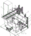
FIG. 1 is a schematic perspective view of the present invention;
FIG. 2 is a schematic block diagram of the present invention;
FIG. 3 is a block diagram of a specific deployment of the platform of the present invention;
FIG. 4 is a schematic diagram of a display sequence of a simulation display area of a central console device and a simulation display area of a top console device according to the present invention;
FIG. 5 is a schematic view of a display sequence of a primary flight instrument simulation display area, a front visor device simulation display area, and a view simulation display area of the present invention;
FIG. 6 is a side elevational view of the overall frame diagram of the present invention;
FIG. 7 is a schematic view of the gantry of the present invention;
FIG. 8 is a flow chart of the design of the frame display and control module;
FIG. 9 is a schematic view of the display contents of the front light shield apparatus simulation display area;
FIG. 10 is a diagram illustrating the content displayed in the simulation display area of the console device;
FIG. 11 is a schematic view of the display contents of the simulation display area of the top control panel device;
FIG. 12 is a flow chart of the control board simulation and display module design;
FIG. 13 is a schematic view of the display contents of the simulation display area of the primary flight instrument;
FIG. 14 is a CAS alarm module design flow diagram.
In the figures, the meaning of the reference numerals is as follows: 1. a base plate; 2. a rack; 3. a main flight instrument simulation display area; 4. a front light shield equipment simulation display area; 5. a central console equipment simulation display area; 6. a guide rail; 7. a steering wheel; 8. pedaling; 9. a top control board device simulation display area; 10. a top control bracket; 11. a seat; 12. a visual simulation display area; 13. a slide rail; 14. a bracket connecting piece; 15. a wheel; 16. a rotating shaft; 17. a cabinet area.
Detailed Description
In order to better understand the technical content of the present invention, specific embodiments are described below with reference to the accompanying drawings. In this disclosure, aspects of the present invention are described with reference to the accompanying drawings, in which a number of illustrative embodiments are shown. Embodiments of the present disclosure are not necessarily defined to include all aspects of the invention. It should be appreciated that the various concepts and embodiments described above, as well as those described in greater detail below, may be implemented in any of numerous ways, as the disclosed concepts and embodiments are not limited to any one implementation. In addition, some aspects of the present disclosure may be used alone, or in any suitable combination with other aspects of the present disclosure.
Referring to fig. 1-2, the present invention provides a technical solution: including a cabinet region 17 and a rack region,
the cabinet area 17 includes a cabinet, a power supply device, a switch, and a debugging display device. Wherein the cabinet is a standard 19-inch cabinet with a height of 38U. The power supply equipment is 220V/50Hz alternating current input power supply equipment, the switch is a 1 kilomega switch, the local area network is formed by the power supply equipment and 6 workstation computers together and used for data interaction, and the debugging display equipment is 1 KVM and used for debugging, displaying and controlling the 6 workstation industrial personal computers.
The platform area comprises a bottom plate 1, a platform 2, a main flight instrument simulation display area 3, a front light shield equipment simulation display area 4, a central console equipment simulation display area 5, a steering wheel 7, pedals 8, a top control board equipment simulation display area 9, a seat 11 and a visual simulation display area 12.
Wherein the cabinet area 17 and the equipment in the rack area are connected by test cables.
The system also comprises a master control module 101, a peripheral data acquisition module 102, a flight simulation excitation module 103, a visual simulation module 104, a control panel simulation and display module 105, an image display and control module 106 and a CAS alarm module 107.
The master control module 101 is used for overall management, coordination and control of other modules in the system.
The peripheral data acquisition module 102 is used for acquiring data of the steering wheel 7 and the pedals 8 and sending the data to the flight simulation excitation module.
The flight simulation excitation module 103 is configured to receive control data of the control panel simulation and display module 105 and excitation data of the peripheral data acquisition module 102, perform resolving of flight parameters, simulation of a flight phase, simulation of an airborne avionic system and a non-avionic system according to a built-in flight dynamics model, and send flight data and excitation data to the visual simulation module 104 and the picture display and control module 106.
The view simulation module 104 is configured to provide a synchronous view simulation during the simulated flight.
The control panel simulation and display module 105 is used for various control panel interfaces of the cockpit front light shield device, the central console and the top control panel to display and control simulation, and sends user control data to the flight simulation excitation module 103.
The image display and control module 106 is configured to receive flight data sent by the flight simulation excitation module 103, and drive the main flight instrument panel to display data of the image model.
The CAS alarm module 107 is configured to simulate a unit alarm logic and drive the screen display and control module 106 to display alarm information.
Each module has a distributed deployment function, and can be operated and displayed on a cabinet area 17 and a rack area 1-16 of the novel cockpit display system rapid prototyping verification platform hardware according to functional characteristics and the connection relation of display equipment.
The workstation computer is a 6-desktop industrial personal computer, and is respectively configured with a multi-screen independent display card, a peripheral data acquisition module 102 of platform software is deployed on the workstation 1, a flight simulation excitation module 103 and a visual simulation module 104 of the platform software are deployed on the workstation 2, a picture display and control module 106 of the platform software is deployed on the workstation 3, a control panel simulation and display module 105 of the platform software is deployed on the workstation 4, a CAS alarm module 107 of the platform software is deployed on the workstation 5, and a master control module 101 of the platform software is deployed on the workstation 6, as shown in fig. 3.
Wherein, the work station 1 is connected and controlled with a front and assistant driver seat steering wheel 7 and pedals 8 of the rack area through cables.
Wherein, the workstation 2 is connected and controlled with the visual simulation display area 12 device of the platform area through a cable.
The workstation 3 is connected and controlled with the main flight instrument simulation display area 3 equipment of the platform area through a cable.
The workstation 4 is connected and controlled with the front light shield device simulation display area 4, the central console device simulation display area 5 and the top control board device simulation display area 9 of the rack area through cables.
The workstation 5 is connected with the debugging display equipment in the cabinet area, and is configured with audio output equipment.
Wherein the workstation 6 is connected with the debugging display equipment of the cabinet area.
Wherein, bottom plate 1 is aluminum alloy or similar functional panel, installs the fixed rack 2 through the trompil above it, plays the effect of whole support.
Wherein, the bottom of the bottom plate 1 is provided with wheels 15, the position of the bottom plate is fixed by using a foot brake in a static state, and the whole structure can be translated back and forth and left and right by releasing the foot brake.
As shown in fig. 4, 5, 6 and 7, the rack 2 is made of an aluminum alloy section, the main flight instrument simulation display area 3 can be translated left and right through an aluminum alloy section four 2-04, the front light shield equipment simulation display area 4 can be translated left and right through an aluminum alloy section three 2-03, the top control bracket 10 can be adjusted up and down through an aluminum alloy section one 2-01, and the aluminum alloy section one 2-01 plays a role in connection and fixation.
Wherein, main flight instrument emulation display area 3 passes through support even 14 to be installed on rack 2, and main flight instrument emulation display area 3 includes 4 15.6 cun touch LCD: 3-01 parts of a display, 3-02 parts of a display, 3-03 parts of a display, 3-04 parts of a display and 3-05 parts of 1 23.8-inch touch liquid crystal display, wherein the 4 parts of 15.6-inch touch liquid crystal displays can be translated back and forth and adjusted in angle through a support connecting piece 14, the 23.8-inch touch liquid crystal display 3-05 is installed on a rack through a rotating shaft 16, and the 23.8-inch touch liquid crystal display 3-05 can be adjusted up and down and adjusted in angle through the self structure of the rotating shaft 16.
Wherein, preceding light shield equipment emulation display area 4 passes through support even 14 to be installed on the rack, and preceding light shield equipment emulation display area 4 includes 2 stations 12.1 cun touch LCD: display 4-01, display 4-06 still include 4 platforms 23.8 cun touch LCD: display 4-02, display 4-03, display 4-04, display 4-05, and also comprises an 8-inch touch liquid crystal display 4-07, which can be translated back and forth and adjusted in angle by bracket connection 14.
Wherein, top accuse board equipment emulation display area 9 is installed on top accuse support 10, and top accuse board equipment emulation display area 9 includes 3 27 cun touch-control LCD: the display 9-01, the display 9-02 and the display 9-03 can be translated back and forth through the aluminum alloy section five 2-05.
Wherein, central console equipment emulation display area 5 is installed on rack 2 through slide rail 13, and central console equipment emulation display area 5 includes 3 23.8 cun touch-control LCD: the display 5-01, the display 5-02 and the display 5-03 can be translated back and forth and adjusted up and down through the sliding rail 13.
The driving wheel and pedal assembly is mounted on the rack through the guide rail, and can be translated back and forth through the guide rail.
The steering wheel 7 is of a double-sided tension spring return structure, the left-right rotation angle is +/-60 degrees, the front-back push-pull angle is +/-30 degrees, and the height of the steering wheel 7 can be adjusted to adapt to different pilot visual angles.
The seat 11 is mounted on the bottom plate 1 and can translate back and forth, and the seat 11 itself can be finely adjusted back and forth and adjusted in height.
Wherein, the vision simulation display area 12 is installed on the rack 2 through the support connecting piece 14, and the vision simulation display area 12 is arranged above the front of the front driving seat and the front driving seat, and comprises 2 liquid crystal touch displays of 23.8 inches: the display 12-01 and the display 12-02 are used for displaying visual pictures, can be adjusted in a front-back angle through the support connecting piece 14, and can be translated left and right through the aluminum alloy section II 2-02.
The master control module 101 is deployed in the workstation 6, as shown in fig. 3, and can implement coordinated control of all other software modules, and can implement flexible configuration adjustment of a demonstration effect on the master control module 101 according to a prototype design of a cockpit display system.
The peripheral data acquisition module 102 is deployed in the workstation 1, and as shown in fig. 3, can acquire an operation instruction of the pilot to operate the steering wheel 7 and the foot pedals 8 in real time, and upload the operation instruction to the flight simulation excitation module 103.
The flight simulation excitation module 103 is deployed in the workstation 2, as shown in fig. 3, provides a flight mechanics modeling and simulation of the aircraft by using an open source flight dynamics software library JSBSim, simulates various data of an avionic simulation system and a non-avionic simulation system by using a self-developed Lua flight simulation engine, combines the various data with flight simulation data, and sends the combined data to the picture display and control module 106 and the view simulation module 104 through the ethernet. The JSBSim supports automatic flight simulation through parameter configuration and also supports manual flight through external input control instructions, and the data source includes the operating instructions of the steering wheel 7 and the foot pedal 8 acquired by the peripheral acquisition module and the operating instructions output by the control panel simulation and display module 105, as shown in fig. 3.
The vision simulation module 104 is deployed in the workstation 2, as shown in fig. 3, and pushes the display content to the vision simulation display area 12, and includes 2 display devices: the display 12-01 and the display 12-02 are, as shown in fig. 5, implemented by adopting mature open source flight simulation software FlightGear for displaying visual simulation, where the FlightGear supports receiving external excitation data for visual display driving, and the data source is flight data output by the flight simulation excitation module 103.
The image display and control module 106 is deployed in the workstation 3, as shown in fig. 3, and pushes the display content to the simulation display area 3 of the primary flight instrument, and includes 5 display devices: display 3-01, display 3-02, display 3-03, display 3-04, display 3-05, as shown in FIG. 5, provide a visual simulation of the following primary flight instrument panel, including: the system comprises a main flight display (PFD), a reference information display (REF), a Navigation Display (ND), an attended unit alarm display (EICAS), a simplified diagram page display, a Beidou short message display, an electronic inspection list display, a fire extinguishing information display, a flight management display (FMS), an airborne maintenance display and the like, wherein the initial picture display is shown in figure 13. The image display and control module 106 can receive the flight data of the flight simulation excitation module 103, the operation instruction of the control panel simulation and display module 105 and the alarm information of the CAS alarm module 107, and display the flight data, the operation instruction and the alarm information in the corresponding image of the simulation display area 3 of the primary flight instrument.
The control panel simulation and display module 105 supports the function of quickly reconstructing a simulation page, and supports the modification and distribution of page layout information or the modification of a page configuration file through the master control module 101 according to prototype design requirements, so that the display/hiding, position, size and other attributes of the panel can be flexibly adjusted, and for a single panel, the arrangement mode of internal controls can be adjusted in such a way. The specific design flow is as follows, as shown in fig. 12:
s201, selecting a picture prototype and a data processing script in a control panel element library, wherein the picture prototype defines the appearance and the state of a control, and the data processing script defines data sent by the control under different states;
s202, associating the picture prototype file with the data processing script to generate a control prototype;
s203, configuring control attributes, such as names, text display, states, value ranges and other information, and generating control instances, wherein each page comprises a plurality of control instances which can be from the same prototype or different prototypes;
s204, defining information such as position coordinates, sizes and the like of each control instance, and generating page instances, wherein each operation board is used as one page instance in general;
and S205, defining information such as position coordinates, resolution and the like of each page, and generating a control panel simulation interface.
The frame display and control module 106 supports the capability of rapidly building and reconstructing a frame display prototype, and according to the prototype design requirement, the master control module 101 modifies and distributes page layout information or modifies a page configuration file, so that the display/hiding, position, size and other attributes of the frame can be flexibly adjusted, and for a single frame, the arrangement mode of the internal controls can be adjusted in such a way. The difference from the control board simulation and display module 105 is that the screen display prototype also needs to receive external excitation data and display the external excitation data in the screen while maintaining the state switching of the screen display prototype and sending an operation instruction, and the specific design flow is as follows, as shown in fig. 8:
s101, according to design requirements and display element icons of a mainstream machine type, a display icon library is established in advance, and the icons are used for describing the appearance characteristics of the control;
and S102, selecting the icons in the icon library, adding basic logic, binding data and generating a control prototype. The control prototype comprises basic logics of the control, such as state change rules, picture display rules, data excitation rules, animation effects and the like;
s103, configuring control attributes, such as information of names, text display, states, value ranges and the like, and generating control instances, wherein each page comprises a plurality of control instances which can be from the same prototype or different prototypes;
s104, defining information such as position coordinates, sizes and the like of each control instance, generating a page prototype, and generally combining the control pieces related to functions into a page;
s105, binding a data processing interface for each page, acquiring data from the interface, binding the data into each control, driving the normal display of a picture, and enabling a page prototype binding the interface and the data to become a page example;
s106. the simulation display area 3 of the main flight instrument consists of 5 display screens, each display screen is divided into windows with different proportions of 1/2, 1/3, 2/3 and the like, and a single window comprises a plurality of page instances, so that the window instances are generated by configuring page layout information;
and S107, configuring the display position of each window according to the prototype design scheme of the cockpit display system, and generating a simulation picture of the main flight instrument.
The control panel simulation and display module 105 is disposed in the workstation 4, as shown in fig. 3, and pushes display contents to the front sunshade device simulation display area 4, the central console device simulation display area 5, and the top control panel device simulation display area 9, where the front sunshade device simulation display area 4 includes 7 display devices supporting touch screen input: the display 4-01, the display 4-02, the display 4-03, the display 4-04, the display 4-05, the display 4-06 and the display 4-07 are provided with simulation pictures of operation control panels such as an MCMW (micro controller molecular weight), a left and right Display Control Panel (DCP), a Flight Control Panel (FCP), a left and right side dimming control box and the like as shown in FIG. 5, and the picture layout is shown in FIG. 9; the simulation display area 5 of the central console device comprises 3 display devices supporting touch screen input: the display 5-01, the display 5-02 and the display 5-03 are provided with a conversion control panel (RCP), an Emission Control Panel (ECP), a multi-function keyboard (MKB), a Cursor Control Device (CCD), an accelerator stage, an engine control panel, a speed reduction plate handle and a flap and slat handle as shown in FIG. 4, and the picture layout is shown in FIG. 9; the simulation display area 9 of the top control panel device comprises 3 display devices supporting touch screen input: the display 9-01, the display 9-02 and the display 9-03 are provided with hydraulic control (HYD), external illumination, cockpit illumination, FUEL control (FUEL), Ground Proximity Warning (GPWS), engine electric gates (ENG 1/ENG 2), APU control and indication (APU) as shown in FIG. 4, and the screen layout is shown in FIG. 11. The simulation control elements of the front light shield device simulation display area 4, the central console device simulation display area 5 and the top control board device simulation display area 9 support a user to operate through a touch screen and send corresponding operation instructions to the flight simulation excitation module 103 and the picture display and control module 106.
The CAS alarm module 107 is disposed in the workstation 5, as shown in fig. 3, and pushes the audio alarm to the audio output device, and the CAS alarm module 107 mainly includes an alarm logic calculation function, an alarm management function, an alarm display function, a main visual alarm trigger function, an audio alarm management function, a flight phase calculation function, and an alarm control function. And the warning logic operation is supported according to the configured warning logic expression and the flight data output by the flight simulation excitation module 103, a warning result is generated, and the audio warning output and CAS warning image display in the image display and control module 106 are driven. The processing flow of the alarm module is as follows, as shown in fig. 14:
s301, firstly, an alarm test case is required to be imported, and relevant attributes of different types of alarm information are defined in the test case, wherein the relevant attributes comprise an alarm text, an alarm level, voice information, alarm logic, a suppression rule and the like;
s302, selecting a test case and extracting information such as attributes, alarm logic expressions, inhibition rules and the like, wherein the test case supports single or multiple test cases;
s303, acquiring appointed alarm logic parameters from the excitation data according to the ICD signal parameter name;
s304, according to the alarm logic expression and the alarm logic parameter, carrying out alarm logic calculation to obtain an alarm logic result;
s305, according to the suppression rule, performing alarm suppression information processing;
and S306, outputting the alarm information to the simulation display area 3 of the primary flight instrument or the audio equipment.
The rapid construction and reconstruction of the prototype verification platform of the cockpit display system are realized by adopting modular and modularized design; hardware equipment basically adopts a goods shelf type product, so that the occupation ratio of the customized equipment is greatly reduced, and the implementation period and the implementation cost of the whole platform are reduced. The structure rack of the customized design adopts universal aluminum alloy section bar raw materials, and the flexible adjustment of each component of the rack is realized through the design of the invention, so that the realization cost is reduced, and the structure rack can adapt to the structural requirement change and the rapid iteration of the early prototype design of the cockpit display system. The touch display screen is matched with software for simulation, the problems of high cost and long period of control panel physical simulation customization are solved, the simulation degree is high, the adaptability and the expansibility are good, the design can be landed by simply modifying the script and the configuration file, and the iteration period of control panel design change in the early prototype design of the cockpit display system is greatly shortened.
The pure software simulation control instrument and the main flight display picture are used, the picture is flexible and configurable, rapid reconstruction is supported, and the method can adapt to rapid iteration of the main flight picture scheme in the early prototype design of the cockpit display system. The software adopts a distributed design idea to ensure the flexibility of software deployment and support the rapid construction and reconstruction of the control panel and the display picture.
By using the implementation mode of the whole set of cockpit display system prototype verification platform provided by the invention, the simulation degree of the prototype implementation of the cockpit display system is ensured, the implementation period and the implementation cost of the prototype platform are reduced, and the prototype platform still has good universality and higher reusability aiming at the transformation or the upgrade of similar machine types due to good adaptability and expandability.
Although embodiments of the present invention have been shown and described, it will be appreciated by those skilled in the art that changes, modifications, substitutions and alterations can be made in these embodiments without departing from the principles and spirit of the invention, the scope of which is defined in the appended claims and their equivalents.
Although the present invention has been described with reference to the preferred embodiments, it is not intended to be limited thereto. Those skilled in the art can make various changes and modifications without departing from the spirit and scope of the invention. Therefore, the protection scope of the present invention should be determined by the appended claims.
Claims (10)
1. A simulation platform for design prototype verification of an aircraft cockpit display system is characterized in that: the method comprises the following steps:
the general control module (101), the general control module (101) is used for carrying out overall management, coordination and control on other modules in the simulation platform;
the system comprises a peripheral data acquisition module (102), wherein the peripheral data acquisition module (102) is used for acquiring peripheral data and sending the peripheral data to a flight simulation excitation module;
the flight simulation excitation module (103), the flight simulation excitation module (103) is used for receiving the control data of the control panel simulation and display module (105) and the excitation data of the peripheral data acquisition module (102), resolving flight parameters, simulating a flight phase and simulating an airborne avionic system and a non-avionic system according to a built-in flight dynamics model, and sending flight data and excitation data to the visual simulation module (104) and the picture display and control module (106);
a view simulation module (104), the view simulation module (104) being configured to provide a synchronized view simulation during a simulated flight;
the control panel simulation and display module (105) is used for various control panel interfaces of the front light shield equipment of the cockpit, the central console and the top control panel to display and control simulation, and sends user control data to the flight simulation excitation module (103);
the picture display and control module (106) is used for receiving flight data sent by the flight simulation excitation module (103) and driving data display of the simulation display area of the main flight instrument panel;
the CAS warning module (107), the CAS warning module (107) is used for simulating the unit warning logic and driving the picture display and control module (106) to display warning information.
2. The simulation platform for design prototype verification of an aircraft cockpit display system of claim 1 wherein: the outer part is provided with a steering wheel (7) and pedals (8).
3. The simulation platform for design prototype verification of an aircraft cockpit display system of claim 2 wherein: the master control module (101), the peripheral data acquisition module (102), the control panel simulation and display module (105), the picture display and control module (106) and the CAS alarm module (107) are respectively arranged on different industrial personal computers, and the visual simulation module (104) and the flight simulation excitation module (103) are arranged on the same industrial personal computer.
4. The simulation platform for design prototype verification of an aircraft cockpit display system of claim 3 wherein: the system also comprises a main flight instrument simulation display area (3), a front shading cover equipment simulation display area (4), a central console equipment simulation display area (5), a top control board equipment simulation display area (9), a visual simulation display area (12) and a cabinet area (17);
an industrial personal computer provided with an external data acquisition module (102) is connected with and controlled by a steering wheel (7) and pedals (8) through cables;
an industrial personal computer provided with a visual simulation module (104) and a flight simulation excitation module (103) is connected with and controlled by a visual simulation display area (12) through a cable;
the industrial personal computer provided with the picture display and control module (106) is connected and controlled with the simulation display area (3) of the main flight instrument through a cable;
an industrial personal computer provided with a control panel simulation and display module (105) is connected and controlled with the front shading cover equipment simulation display area (4), the central console equipment simulation display area (5) and the top control panel equipment simulation display area (9) through cables;
the industrial personal computers respectively provided with the master control module (101) and the CAS warning module (107) are connected with the cabinet area (17) through cables, and the industrial personal computers provided with the CAS warning module (107) are configured with audio output equipment.
5. The simulation platform for design prototype verification of an aircraft cockpit display system of claim 4 wherein: cabinet district (17) are including rack, power supply unit, switch and debugging display device, the rack is the 19 inch racks of standard, highly is 38U, power supply unit is 220V 50Hz AC input power supply unit, and the switch is 1 kilomega switch, with the industrial computer constitutes the local area network jointly and is used for the data interaction, the debugging display device is 1 KVM, is used for the debugging of industrial computer to show and control.
6. The simulation platform for design prototype verification of an aircraft cockpit display system of claim 4 wherein: the device also comprises a bottom plate (1) and a rack (2), wherein the rack (2) is fixed on the bottom plate (1);
the main flight instrument simulation display area (3) is arranged on the rack (2), the main flight instrument simulation display area (3) comprises 5 touch liquid crystal displays, wherein 4 touch liquid crystal displays are arranged on the rack (2) through a support connecting piece (14), the 4 touch liquid crystal displays are translated back and forth and adjusted in angle through the support connecting piece (14), 1 touch liquid crystal display is arranged on the rack (2) through a rotating shaft (16), and the 1 touch liquid crystal display can be adjusted up and down and adjusted in angle through the rotating shaft (16);
the front light shield equipment simulation display area (4) is arranged on the rack, the front light shield equipment simulation display area (4) comprises 7 touch liquid crystal displays, and the 7 touch liquid crystal displays can be translated forwards and backwards and adjusted in angle through the support connecting piece (14).
7. The simulation platform for design prototype verification of an aircraft cockpit display system of claim 6 wherein: the simulation display area (9) of the top control board equipment is arranged on the rack (2) through a top control bracket (10), the simulation display area (9) of the top control board equipment comprises 3 touch liquid crystal displays, the 3 touch liquid crystal displays are arranged on the rack (2), and the 3 touch liquid crystal displays can translate back and forth on the rack (2);
the central control platform equipment simulation display area (5) is arranged on the rack (2), the central control platform equipment simulation display area (5) comprises 3 touch liquid crystal displays, the 3 touch liquid crystal displays are arranged on the rack (2) through sliding rails (13), and the 3 touch liquid crystal displays can translate back and forth and adjust up and down through the sliding rails (13);
the visual simulation display area (12) is arranged on the rack (2), the visual simulation display area (12) is arranged in front of and above a front driving seat and a front and upper auxiliary driving seat, the visual simulation display area (12) comprises 2 liquid crystal touch displays for visual picture display, the 2 liquid crystal touch displays are arranged on the rack (2) through a support connecting piece (14), and the 2 liquid crystal touch displays can be adjusted in front and back angles through the support connecting piece (14) and can be translated on the rack (2) in a left-right mode;
the combined piece of the steering wheel (7) and the pedals (8) is arranged on the rack (2) through the guide rail (6), the combined piece can be translated back and forth through the guide rail (6), the steering wheel (7) adopts a double-sided tension spring return structure, the left and right rotation angles are +/-60 degrees, the front and back push-pull angles are +/-30 degrees, and the height of the steering wheel (7) can be adjusted to adapt to different pilot visual angles.
8. The simulation platform for design prototype verification of an aircraft cockpit display system of claim 7 wherein: the steps of the picture display and control module (106) for rapidly building and reconstructing the picture display prototype are as follows:
s101, according to design requirements and display element icons of a mainstream machine type, a display icon library is established in advance, and the icons are used for describing the appearance characteristics of the control;
s102, selecting the icons in the icon library, adding basic logic, binding data and generating a control prototype, wherein the control prototype comprises the basic logic of the control, and the basic logic comprises a state change rule, a picture display rule, a data excitation rule and an animation effect;
s103, configuring control attributes including name, text display, state and value range information, generating control instances, wherein each page comprises a plurality of control instances which can be from the same prototype or different prototypes;
s104, defining position coordinates and size information of each control instance, generating a page prototype, and combining the control pieces related to functions into a page;
s105, binding a data processing interface for each page, acquiring data from the interface, binding the data into each control, driving the normal display of a picture, and enabling a page prototype binding the interface and the data to become a page example;
s106, each touch liquid crystal display in the simulation display area of the primary flight instrument is divided into windows with different proportions, such as 1/2, 1/3, 2/3 and the like, and a single window comprises a plurality of page instances, so that the window instances need to be generated by configuring page layout information;
and S107, configuring the display position of each window according to the prototype design scheme of the cockpit display system, and generating a simulation picture of the main flight instrument.
9. The simulation platform for design prototype verification of an aircraft cockpit display system of claim 1 wherein: the steps of the control panel simulation and display module (105) for rapidly reconstructing the simulation page are as follows:
s201, selecting a picture prototype and a data processing script in a control panel element library, wherein the picture prototype defines the appearance and the state of a control, and the data processing script defines data sent by the control under different states;
s202, associating the picture prototype file with the data processing script to generate a control prototype;
s203, configuring control attributes which comprise information such as names, text display, states, value ranges and the like, generating control instances, wherein each page comprises a plurality of control instances which can be from the same prototype or different prototypes;
s204, defining information such as position coordinates, sizes and the like of each control instance, and generating page instances, wherein each operation board is used as one page instance in general;
and S205, defining information such as position coordinates, resolution and the like of each page, and generating a control panel simulation interface.
10. The simulation platform for design prototype verification of an aircraft cockpit display system of claim 7 wherein: the processing flow of the CAS warning module (107) is as follows;
s301, firstly, an alarm test case is required to be imported, and relevant attributes of different types of alarm information are defined in the test case, wherein the attributes comprise an alarm text, an alarm level, voice information, alarm logic and a suppression rule;
s302, selecting a test case and extracting attributes, alarm logic expressions and inhibition rule information, wherein the test case supports single or multiple test cases;
s303, acquiring appointed alarm logic parameters from the excitation data according to the ICD signal parameter name;
s304, according to the alarm logic expression and the alarm logic parameter, carrying out alarm logic calculation to obtain an alarm logic result;
s305, according to the suppression rule, performing alarm suppression information processing;
and S306, outputting the alarm information to the simulation display area (3) of the primary flight instrument or audio equipment.
Priority Applications (1)
| Application Number | Priority Date | Filing Date | Title |
|---|---|---|---|
| CN202111301410.6A CN113741220B (en) | 2021-11-04 | 2021-11-04 | A simulation platform for prototype verification of aircraft cockpit display system design |
Applications Claiming Priority (1)
| Application Number | Priority Date | Filing Date | Title |
|---|---|---|---|
| CN202111301410.6A CN113741220B (en) | 2021-11-04 | 2021-11-04 | A simulation platform for prototype verification of aircraft cockpit display system design |
Publications (2)
| Publication Number | Publication Date |
|---|---|
| CN113741220A true CN113741220A (en) | 2021-12-03 |
| CN113741220B CN113741220B (en) | 2022-03-29 |
Family
ID=78727453
Family Applications (1)
| Application Number | Title | Priority Date | Filing Date |
|---|---|---|---|
| CN202111301410.6A Active CN113741220B (en) | 2021-11-04 | 2021-11-04 | A simulation platform for prototype verification of aircraft cockpit display system design |
Country Status (1)
| Country | Link |
|---|---|
| CN (1) | CN113741220B (en) |
Cited By (3)
| Publication number | Priority date | Publication date | Assignee | Title |
|---|---|---|---|---|
| CN115497360A (en) * | 2022-08-26 | 2022-12-20 | 北京摩诘创新科技股份有限公司 | Visual display system of flight simulator and control method |
| CN116049974A (en) * | 2022-12-13 | 2023-05-02 | 商飞软件有限公司 | An aircraft warning logic design and simulation system and design and simulation method |
| CN116755355A (en) * | 2023-08-23 | 2023-09-15 | 商飞软件有限公司 | Comprehensive test system and test method of airborne flight management system |
Citations (8)
| Publication number | Priority date | Publication date | Assignee | Title |
|---|---|---|---|---|
| US5582518A (en) * | 1988-09-09 | 1996-12-10 | Thomson-Csf | System for restoring the visual environment of a pilot in a simulator |
| CN105427379A (en) * | 2015-12-02 | 2016-03-23 | 上海航空电器有限公司 | Flight visual simulation system for testing ground proximity warning system |
| CN107274747A (en) * | 2017-08-01 | 2017-10-20 | 中国航空工业集团公司西安飞机设计研究所 | A kind of aircraft cockpit ergonomic assessment system |
| CN109050948A (en) * | 2018-09-04 | 2018-12-21 | 中国商用飞机有限责任公司北京民用飞机技术研究中心 | The aobvious control distributing adjustment system of one kind |
| CN110187681A (en) * | 2019-05-09 | 2019-08-30 | 中国电子科技集团公司电子科学研究院 | Reconfigurable Cockpit Display Control System |
| CN112068831A (en) * | 2020-08-13 | 2020-12-11 | 中国航空无线电电子研究所 | Display system prototype configuration development tool |
| CN112287456A (en) * | 2020-10-29 | 2021-01-29 | 中国航空工业集团公司洛阳电光设备研究所 | Modularized configurable flight simulator for engineering |
| CN112598958A (en) * | 2020-12-17 | 2021-04-02 | 中国航空综合技术研究所 | Flexible simulation cabin man-machine work efficiency test system and evaluation method thereof |
-
2021
- 2021-11-04 CN CN202111301410.6A patent/CN113741220B/en active Active
Patent Citations (8)
| Publication number | Priority date | Publication date | Assignee | Title |
|---|---|---|---|---|
| US5582518A (en) * | 1988-09-09 | 1996-12-10 | Thomson-Csf | System for restoring the visual environment of a pilot in a simulator |
| CN105427379A (en) * | 2015-12-02 | 2016-03-23 | 上海航空电器有限公司 | Flight visual simulation system for testing ground proximity warning system |
| CN107274747A (en) * | 2017-08-01 | 2017-10-20 | 中国航空工业集团公司西安飞机设计研究所 | A kind of aircraft cockpit ergonomic assessment system |
| CN109050948A (en) * | 2018-09-04 | 2018-12-21 | 中国商用飞机有限责任公司北京民用飞机技术研究中心 | The aobvious control distributing adjustment system of one kind |
| CN110187681A (en) * | 2019-05-09 | 2019-08-30 | 中国电子科技集团公司电子科学研究院 | Reconfigurable Cockpit Display Control System |
| CN112068831A (en) * | 2020-08-13 | 2020-12-11 | 中国航空无线电电子研究所 | Display system prototype configuration development tool |
| CN112287456A (en) * | 2020-10-29 | 2021-01-29 | 中国航空工业集团公司洛阳电光设备研究所 | Modularized configurable flight simulator for engineering |
| CN112598958A (en) * | 2020-12-17 | 2021-04-02 | 中国航空综合技术研究所 | Flexible simulation cabin man-machine work efficiency test system and evaluation method thereof |
Cited By (4)
| Publication number | Priority date | Publication date | Assignee | Title |
|---|---|---|---|---|
| CN115497360A (en) * | 2022-08-26 | 2022-12-20 | 北京摩诘创新科技股份有限公司 | Visual display system of flight simulator and control method |
| CN116049974A (en) * | 2022-12-13 | 2023-05-02 | 商飞软件有限公司 | An aircraft warning logic design and simulation system and design and simulation method |
| CN116755355A (en) * | 2023-08-23 | 2023-09-15 | 商飞软件有限公司 | Comprehensive test system and test method of airborne flight management system |
| CN116755355B (en) * | 2023-08-23 | 2023-10-20 | 商飞软件有限公司 | Comprehensive test system and test method of airborne flight management system |
Also Published As
| Publication number | Publication date |
|---|---|
| CN113741220B (en) | 2022-03-29 |
Similar Documents
| Publication | Publication Date | Title |
|---|---|---|
| CN113741220B (en) | A simulation platform for prototype verification of aircraft cockpit display system design | |
| CA2052155C (en) | Glass trainer | |
| CN101251959B (en) | General-purpose aviation simulator based on virtual operation | |
| Shukla et al. | Virtual manufacturing: an overview | |
| CN100568317C (en) | Control apparatus for airplane synthetic guarantee simulated training system | |
| US5224861A (en) | Training device onboard instruction station | |
| CN112287456A (en) | Modularized configurable flight simulator for engineering | |
| US20150111180A1 (en) | Methods, systems, and computer readable media for cursor and text entry for aircraft interface simulation | |
| CN201242814Y (en) | Single-cargo single-seat airplane synthesis safeguard simulation training system control device | |
| Boring et al. | Digital full-scope mockup of a conventional nuclear power plant control room, Phase 1: installation of a utility simulator at the Idaho national laboratory | |
| CA2467008A1 (en) | Recurrent training machine | |
| Hoffmann et al. | Extending the desktop workplace by a portable virtual reality system | |
| Boring et al. | Analog, digital, or enhanced human-system interfaces? results of an operator-in-the-loop study on main control room modernization for a nuclear power plant | |
| Grandl | Virtual process week in the experimental vehicle build at BMW AG | |
| CN206249032U (en) | A kind of man-machine interactive system based on emulation aircraft | |
| Geiger et al. | A zoomable user interface for presenting hierarchical diagrams on large screens | |
| EP3023967A1 (en) | Methods, systems, and computer readable media for cursor and text entry for aircraft interface simulation | |
| Mayer et al. | Ten years of operating a center with large-scale virtual-reality installations: Developments and learnings | |
| Xiyun et al. | Application of virtual reality technology in nuclear power plant control room simulator | |
| Bass et al. | Constructing wearable computers for maintenance applications | |
| EP4564332A1 (en) | Virtualized avionics | |
| Roesler et al. | Video prototyping for interaction design across multiple displays in the commercial flight deck | |
| Theunissen | D3S-The Delphins Display Design System | |
| Panfilov | Integrating VR into aerospace simulation | |
| Kuang et al. | Civil Aircraft Cockpit Human Machine Interactive Dynamic Assessment Quality Improvement Based on System Engineering |
Legal Events
| Date | Code | Title | Description |
|---|---|---|---|
| PB01 | Publication | ||
| PB01 | Publication | ||
| SE01 | Entry into force of request for substantive examination | ||
| SE01 | Entry into force of request for substantive examination | ||
| GR01 | Patent grant | ||
| GR01 | Patent grant | ||
| CP03 | Change of name, title or address |
Address after: No. 2 Yongshun Road, Qinhuai District, Nanjing City, Jiangsu Province 211000 Patentee after: Jiangsu Juntian Electronic Technology Co.,Ltd. Country or region after: China Address before: 210000 fifth floor, teaching building, No. 14, Tiantang new village, Qinhuai District, Nanjing City, Jiangsu Province Patentee before: XINCHUANHUI ELECTRONIC TECHNOLOGY Co.,Ltd. Country or region before: China |
|
| CP03 | Change of name, title or address |