CN113680524A - Fe-PDMS composite material-based oil abrasive particle separation device and manufacturing method thereof - Google Patents

Fe-PDMS composite material-based oil abrasive particle separation device and manufacturing method thereof Download PDF

Info

Publication number
CN113680524A
CN113680524A CN202111117231.7A CN202111117231A CN113680524A CN 113680524 A CN113680524 A CN 113680524A CN 202111117231 A CN202111117231 A CN 202111117231A CN 113680524 A CN113680524 A CN 113680524A
Authority
CN
China
Prior art keywords
pdms
coating
permanent magnet
oil
channel
Prior art date
Legal status (The legal status is an assumption and is not a legal conclusion. Google has not performed a legal analysis and makes no representation as to the accuracy of the status listed.)
Pending
Application number
CN202111117231.7A
Other languages
Chinese (zh)
Inventor
王俊生
赵鹏璐
赵凯
Current Assignee (The listed assignees may be inaccurate. Google has not performed a legal analysis and makes no representation or warranty as to the accuracy of the list.)
Dalian Maritime University
Original Assignee
Dalian Maritime University
Priority date (The priority date is an assumption and is not a legal conclusion. Google has not performed a legal analysis and makes no representation as to the accuracy of the date listed.)
Filing date
Publication date
Application filed by Dalian Maritime University filed Critical Dalian Maritime University
Priority to CN202111117231.7A priority Critical patent/CN113680524A/en
Publication of CN113680524A publication Critical patent/CN113680524A/en
Pending legal-status Critical Current

Links

Images

Classifications

    • BPERFORMING OPERATIONS; TRANSPORTING
    • B03SEPARATION OF SOLID MATERIALS USING LIQUIDS OR USING PNEUMATIC TABLES OR JIGS; MAGNETIC OR ELECTROSTATIC SEPARATION OF SOLID MATERIALS FROM SOLID MATERIALS OR FLUIDS; SEPARATION BY HIGH-VOLTAGE ELECTRIC FIELDS
    • B03CMAGNETIC OR ELECTROSTATIC SEPARATION OF SOLID MATERIALS FROM SOLID MATERIALS OR FLUIDS; SEPARATION BY HIGH-VOLTAGE ELECTRIC FIELDS
    • B03C1/00Magnetic separation
    • B03C1/02Magnetic separation acting directly on the substance being separated
    • B03C1/025High gradient magnetic separators
    • B03C1/031Component parts; Auxiliary operations
    • B03C1/033Component parts; Auxiliary operations characterised by the magnetic circuit
    • B03C1/0332Component parts; Auxiliary operations characterised by the magnetic circuit using permanent magnets
    • BPERFORMING OPERATIONS; TRANSPORTING
    • B29WORKING OF PLASTICS; WORKING OF SUBSTANCES IN A PLASTIC STATE IN GENERAL
    • B29CSHAPING OR JOINING OF PLASTICS; SHAPING OF MATERIAL IN A PLASTIC STATE, NOT OTHERWISE PROVIDED FOR; AFTER-TREATMENT OF THE SHAPED PRODUCTS, e.g. REPAIRING
    • B29C39/00Shaping by casting, i.e. introducing the moulding material into a mould or between confining surfaces without significant moulding pressure; Apparatus therefor
    • B29C39/02Shaping by casting, i.e. introducing the moulding material into a mould or between confining surfaces without significant moulding pressure; Apparatus therefor for making articles of definite length, i.e. discrete articles
    • B29C39/10Shaping by casting, i.e. introducing the moulding material into a mould or between confining surfaces without significant moulding pressure; Apparatus therefor for making articles of definite length, i.e. discrete articles incorporating preformed parts or layers, e.g. casting around inserts or for coating articles
    • BPERFORMING OPERATIONS; TRANSPORTING
    • B29WORKING OF PLASTICS; WORKING OF SUBSTANCES IN A PLASTIC STATE IN GENERAL
    • B29CSHAPING OR JOINING OF PLASTICS; SHAPING OF MATERIAL IN A PLASTIC STATE, NOT OTHERWISE PROVIDED FOR; AFTER-TREATMENT OF THE SHAPED PRODUCTS, e.g. REPAIRING
    • B29C39/00Shaping by casting, i.e. introducing the moulding material into a mould or between confining surfaces without significant moulding pressure; Apparatus therefor
    • B29C39/22Component parts, details or accessories; Auxiliary operations
    • B29C39/26Moulds or cores
    • BPERFORMING OPERATIONS; TRANSPORTING
    • B29WORKING OF PLASTICS; WORKING OF SUBSTANCES IN A PLASTIC STATE IN GENERAL
    • B29CSHAPING OR JOINING OF PLASTICS; SHAPING OF MATERIAL IN A PLASTIC STATE, NOT OTHERWISE PROVIDED FOR; AFTER-TREATMENT OF THE SHAPED PRODUCTS, e.g. REPAIRING
    • B29C69/00Combinations of shaping techniques not provided for in a single one of main groups B29C39/00 - B29C67/00, e.g. associations of moulding and joining techniques; Apparatus therefore

Landscapes

  • Engineering & Computer Science (AREA)
  • Mechanical Engineering (AREA)
  • Physical Or Chemical Processes And Apparatus (AREA)

Abstract

本发明提供一种基于Fe‑PDMS复合材料的油液磨粒分离装置及其制作方法。装置,包括:玻璃基底、PDMS层、微通道、永磁体、Fe‑PDMS涂层。Fe‑PDMS复合材料保留了铁的铁磁性同时又具有PDMS的良好粘性与可塑性,可较容易的以小尺寸设置于微通道一侧,在永磁体的磁化下可在微通道内形成可观的磁场梯度。Fe‑PDMS涂层可在刮涂时选择不同凹状模具以形成不同结构,且外部永磁体与微通道的距离可调,可以灵活选择分离出油液中的磁性磨粒与非磁性磨粒,大尺寸磁性磨粒与小尺寸磁性磨粒。本发明通过一种新的复合材料Fe‑PDMS在微通道中产生磁场梯度,实现油液中不同大小、或磁性不同的磨粒的有效分离。该油液磨粒分离装置制作简单,效果明显,为后续油液中磨粒的计数与检测创造了有利条件。

Figure 202111117231

The invention provides an oil-liquid abrasive particle separation device based on Fe-PDMS composite material and a manufacturing method thereof. Device, including: glass substrate, PDMS layer, microchannel, permanent magnet, Fe-PDMS coating. The Fe-PDMS composite retains the ferromagnetism of iron and has the good viscosity and plasticity of PDMS. It can be easily arranged on one side of the microchannel with a small size, and a considerable magnetic field can be formed in the microchannel under the magnetization of the permanent magnet. gradient. Fe-PDMS coating can choose different concave molds to form different structures during blade coating, and the distance between the external permanent magnet and the microchannel can be adjusted, and the magnetic abrasive particles and non-magnetic abrasive particles in the oil can be flexibly separated. Size magnetic abrasive grains and small size magnetic abrasive grains. The invention generates a magnetic field gradient in the microchannel through a new composite material Fe-PDMS, so as to realize the effective separation of abrasive particles with different sizes or different magnetic properties in the oil. The oil-liquid abrasive particle separation device is simple to manufacture and has obvious effect, which creates favorable conditions for the counting and detection of abrasive particles in the subsequent oil liquid.

Figure 202111117231

Description

Fe-PDMS composite material-based oil abrasive particle separation device and manufacturing method thereof
Technical Field
The invention relates to the technical field of microparticle separation, in particular to an oil abrasive particle separation device based on a Fe-PDMS composite material and a manufacturing method thereof.
Background
In recent years, the detection of lubricating oils has become increasingly important in the transportation and manufacturing industries. The lubricating oil with the service life exceeding the effective service life causes frequent equipment failure, frequent oil change causes extremely high operation cost, and many enterprises need to find an ideal threshold value between cost reduction and equipment failure rate reduction, so that the lubricating oil detection technology is widely concerned. Wherein the accumulation of metal abrasive particles due to equipment wear is a major cause of equipment failure.
The micro-fluidic chip technology developed at a high speed in recent years provides a new platform for analysis and treatment of lubricating oil. The technology focuses the demands of some laboratories on a tiny platform, and has the advantages of miniaturization, high integration level, less sample consumption, rapid reaction time and the like. Among them, a common manipulation method of microparticles includes: optical, magnetic, thermal, chemical, acoustical, and electrical. The magnetophoresis has the characteristics of low cost, easiness in realization, non-hydrolysis of a magnetic field and the like, and is very suitable for separating magnetic and non-magnetic metal abrasive particles.
Magnetophoresis refers to the phenomenon of "swimming" certain particles in a magnetic field. The magnitude of the magnetophoretic force is proportional to the particle size of the particles, and the direction of the magnetophoretic force is determined by the difference in magnetic susceptibility between the particles and the surrounding medium. When the magnetic susceptibility of the particles is higher than that of the surrounding medium, the particles will move to the region with higher magnetic field gradient under the action of positive magnetophoresis force. Conversely, if the magnetic susceptibility of the particles is lower than that of the surrounding medium, they will be subjected to negative magnetophoretic forces and move towards regions of lower magnetic field gradient. By applying magnetophoretic force in the vertical direction of fluid flow, the metal abrasive particles with different characteristics are deflected to different degrees, so that the metal abrasive particles are separated.
Disclosure of Invention
According to the technical problem, an oil-liquid abrasive particle separation device based on the Fe-PDMS composite material and a manufacturing method thereof are provided. According to the invention, a magnetic field gradient is generated in the microchannel through a novel composite material Fe-PDMS, so that effective separation of abrasive particles with different sizes or different magnetism in oil can be realized. The oil abrasive particle separating device is simple to manufacture, obvious in effect and capable of creating favorable conditions for counting and detecting abrasive particles in subsequent oil.
The technical means adopted by the invention are as follows:
an oil abrasive particle separation device based on Fe-PDMS composite material comprises:
the glass substrate is used for blade coating the Fe-PDMS coating;
the PDMS layer is attached to the glass substrate to form a micro-channel;
a microchannel for flowing a fluid containing particles therethrough, the microchannel comprising two liquid inlets and three liquid outlets;
the permanent magnet is arranged on one side of the micro-channel and used for generating a magnetic field;
and the Fe-PDMS coating is arranged between the micro-channel and the permanent magnet.
Furthermore, one surface of the PDMS layer is provided with a concave flow channel, and the PDMS layer provided with the concave flow channel is attached to the glass substrate to form a micro-channel.
Further, a rectangular groove for embedding the Fe-PDMS coating is arranged at a position 30 micrometers away from the side surface of the microchannel.
Further, the Fe-PDMS coating is of a convex structure, and is a ferromagnetic material formed by mixing 1 micron spherical iron particles and PDMS according to a certain proportion.
Further, the area of the rectangular groove is larger than that of the Fe-PDMS coating.
Further, the distance between the permanent magnet and the microchannel is adjustable.
Further, the length of the permanent magnet is larger than that of the Fe-PDMS coating, and the permanent magnet is aligned with the center of the Fe-PDMS coating and is arranged on the same side of the microchannel.
Further, the height of the micro-channel is equal to that of the Fe-PDMS coating, so that the PDMS coating is tightly attached to the glass substrate, and the Fe-PDMS coating is aligned to the rectangular groove during attachment.
The invention also provides a manufacturing method of the oil-liquid abrasive particle separation device based on the Fe-PDMS composite material, which comprises the following steps:
s1, preparing PDMS gel, mixing PDMS with a curing agent and uniformly stirring, wherein the ratio of PDMS to the curing agent is 10: 1;
s2, preparing Fe-PDMS, mixing and stirring 1 micron spherical iron particles and PDMS gel for 20 minutes, and standing for 2 hours, wherein the mass fraction of the iron particles is 70%;
s3, pouring PDMS gel on the silicon wafer with the convex mould, taking off and cutting after shaping to form a PDMS layer with the micro-channel;
s4, blade-coating the well-placed Fe-PDMS on the glass substrate with the concave mould, and removing the concave mould after shaping to form an Fe-PDMS coating on the glass substrate;
s5, attaching the PDMS layer to the glass substrate, and embedding the Fe-PDMS coating into the rectangular groove on the PDMS layer;
s6, placing the permanent magnet on the glass substrate with the PDMS layer on the side of the Fe-PDMS coating, aligning the permanent magnet with the center of the Fe-PDMS coating, and non-permanently fixing the permanent magnet to enable the distance between the permanent magnet and the micro-channel to be adjustable.
Compared with the prior art, the invention has the following advantages:
1. according to the oil abrasive particle separation device provided by the invention, a new composite material Fe-PDMS generates a magnetic field gradient in the micro-channel, so that the effective separation of abrasive particles with different sizes or different magnetism in oil can be realized. The oil abrasive particle separating device is simple to manufacture, obvious in effect and capable of creating favorable conditions for counting and detecting abrasive particles in subsequent oil.
2. The oil abrasive particle separation device provided by the invention is simple in manufacturing method, and materials can be purchased and easily obtained. The novel Fe-PDMS composite material retains the ferromagnetism of iron, has good viscosity and plasticity of PDMS, can be easily arranged on one side of a micro-channel in a small size, and can form considerable magnetic field gradient in the micro-channel under the magnetization of a permanent magnet.
3. According to the oil abrasive particle separating device provided by the invention, different concave molds can be selected for forming different structures during blade coating of the Fe-PDMS coating, the distance between the external permanent magnet and the micro-channel is adjustable, and the magnetic abrasive particles and the non-magnetic abrasive particles in oil, namely large-size magnetic abrasive particles and small-size magnetic abrasive particles, can be flexibly selected and separated.
For the reasons, the invention can be widely popularized in the fields of microparticle separation and the like.
Drawings
In order to more clearly illustrate the embodiments of the present invention or the technical solutions in the prior art, the drawings needed to be used in the description of the embodiments or the prior art will be briefly introduced below, and it is obvious that the drawings in the following description are some embodiments of the present invention, and for those skilled in the art, other drawings can be obtained according to these drawings without creative efforts.
Fig. 1 is a schematic structural diagram of an oil-liquid abrasive particle separating device according to an embodiment of the present invention.
Fig. 2 is a schematic structural diagram of an oil-liquid abrasive particle separating device according to another embodiment of the present invention.
Fig. 3 is a schematic structural diagram of an oil-liquid abrasive particle separating device according to another embodiment of the present invention.
Fig. 4 is a partial top view of an oil-abrasive particle separator according to an embodiment of the present invention.
In the figure: 1. a glass substrate; 2. a PDMS layer; 3. a microchannel; 31. a first liquid inlet; 32. a second liquid inlet; 33. a first liquid outlet; 34. a second liquid outlet; 35. a third liquid outlet; 4. a permanent magnet; 41. a single-stage Fe-PDMS coating; 42. a two-stage Fe-PDMS coating; 43. a three-stage Fe-PDMS coating; D. distance of permanent magnet from microchannel.
Detailed Description
It should be noted that the embodiments and features of the embodiments may be combined with each other without conflict. The present invention will be described in detail below with reference to the embodiments with reference to the attached drawings.
In order to make the objects, technical solutions and advantages of the embodiments of the present invention clearer, the technical solutions in the embodiments of the present invention will be clearly and completely described below with reference to the drawings in the embodiments of the present invention, and it is obvious that the described embodiments are only a part of the embodiments of the present invention, and not all of the embodiments. The following description of at least one exemplary embodiment is merely illustrative in nature and is in no way intended to limit the invention, its application, or uses. All other embodiments, which can be derived by a person skilled in the art from the embodiments given herein without making any creative effort, shall fall within the protection scope of the present invention.
It is noted that the terminology used herein is for the purpose of describing particular embodiments only and is not intended to be limiting of exemplary embodiments according to the invention. As used herein, the singular forms "a", "an" and "the" are intended to include the plural forms as well, and it should be understood that when the terms "comprises" and/or "comprising" are used in this specification, they specify the presence of stated features, steps, operations, devices, components, and/or combinations thereof, unless the context clearly indicates otherwise.
The relative arrangement of the components and steps, the numerical expressions and numerical values set forth in these embodiments do not limit the scope of the present invention unless specifically stated otherwise. Meanwhile, it should be understood that the sizes of the respective portions shown in the drawings are not drawn in an actual proportional relationship for the convenience of description. Techniques, methods, and apparatus known to those of ordinary skill in the relevant art may not be discussed in detail but are intended to be part of the specification where appropriate. Any specific values in all examples shown and discussed herein are to be construed as exemplary only and not as limiting. Thus, other examples of the exemplary embodiments may have different values. It should be noted that: like reference numbers and letters refer to like items in the following figures, and thus, once an item is defined in one figure, further discussion thereof is not required in subsequent figures.
In the description of the present invention, it is to be understood that the orientation or positional relationship indicated by the directional terms such as "front, rear, upper, lower, left, right", "lateral, vertical, horizontal" and "top, bottom", etc., are generally based on the orientation or positional relationship shown in the drawings, and are used for convenience of description and simplicity of description only, and in the absence of any contrary indication, these directional terms are not intended to indicate and imply that the device or element so referred to must have a particular orientation or be constructed and operated in a particular orientation, and therefore should not be considered as limiting the scope of the present invention: the terms "inner and outer" refer to the inner and outer relative to the profile of the respective component itself.
Spatially relative terms, such as "above … …," "above … …," "above … …," "above," and the like, may be used herein for ease of description to describe one device or feature's spatial relationship to another device or feature as illustrated in the figures. It will be understood that the spatially relative terms are intended to encompass different orientations of the device in use or operation in addition to the orientation depicted in the figures. For example, if a device in the figures is turned over, devices described as "above" or "on" other devices or configurations would then be oriented "below" or "under" the other devices or configurations. Thus, the exemplary term "above … …" can include both an orientation of "above … …" and "below … …". The device may be otherwise variously oriented (rotated 90 degrees or at other orientations) and the spatially relative descriptors used herein interpreted accordingly.
It should be noted that the terms "first", "second", and the like are used to define the components, and are only used for convenience of distinguishing the corresponding components, and the terms have no special meanings unless otherwise stated, and therefore, the scope of the present invention should not be construed as being limited.
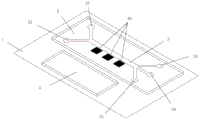
As shown in fig. 1 to 3, the present invention provides an oil abrasive particle separating device based on Fe-PDMS composite material, comprising:
the glass substrate 1 is used for blade coating of an Fe-PDMS coating;
the PDMS layer 2 is attached to the glass substrate 1 to form a micro-channel 3;
a microchannel 3 for flowing a fluid containing particles therethrough, including two liquid inlets and three liquid outlets; the two liquid inlets are respectively a first liquid inlet 31 for flowing sheath liquid and a second liquid inlet 32 for flowing oil liquid, and the three liquid outlets are respectively a first liquid outlet 33, a second liquid outlet 34 and a third liquid outlet 35 for flowing separated particles;
a permanent magnet 4 disposed at one side of the microchannel 3 for generating a magnetic field;
and the Fe-PDMS coating is arranged between the micro-channel 3 and the permanent magnet 4.
In a specific implementation, as a preferred embodiment of the present invention, a concave flow channel is disposed on one surface of the PDMS layer 2, and the PDMS layer 2 having the concave flow channel is bonded to the glass substrate 1 to form the micro channel 3.
In specific implementation, as a preferred embodiment of the present invention, a rectangular groove for embedding the Fe-PDMS coating is disposed at a position 30 μm away from the side surface of the microchannel 3.
In specific implementation, as a preferred embodiment of the present invention, the Fe-PDMS coating is a ferromagnetic material formed by mixing 1 μm spherical iron particles and PDMS according to a certain ratio. In the present embodiment, the Fe-PDMS coating includes a single-stage Fe-PDMS coating 41 as shown in FIG. 1, a two-stage Fe-PDMS coating 42 as shown in FIG. 2, and a three-stage Fe-PDMS coating 43 as shown in FIG. 3; a novel ferromagnetic composite material Fe-PDMS is arranged on one side of the micro-channel 3, the novel Fe-PDMS composite material retains the ferromagnetic property of iron and has good viscosity and plasticity of PDMS, and the Fe-PDMS forms a magnetic field gradient in the micro-channel 3 under the magnetization effect of the external permanent magnet 4. Under the action of the permanent magnet 4, a higher magnetic field gradient exists in the microchannel 3 close to the edge of the single-segment Fe-PDMS coating 41 shown in FIG. 1. The microchannel 3 will have a high magnetic field gradient near the edges and in one space of the two-segment Fe-PDMS coating 42 shown in fig. 2. The microchannel 3 has a high magnetic field gradient near the edge and two spaces of the three-stage Fe-PDMS coating 43 shown in FIG. 3. And when the Fe-PDMS coating is segmented more, more high magnetic field gradient areas are arranged on one side of the micro-channel 3 close to the Fe-PDMS coating.
In specific implementation, as a preferred embodiment of the present invention, the area of the rectangular groove is larger than the area of the Fe-PDMS coating.
In specific implementation, as a preferred embodiment of the present invention, the length of the permanent magnet is greater than the length of the Fe-PDMS coating, and the permanent magnet is aligned with the center of the Fe-PDMS coating and is disposed on the same side of the microchannel. To ensure full magnetization of the entire Fe-PDMS coating.
In specific implementation, as a preferred embodiment of the present invention, the distance between the permanent magnet and the microchannel is adjustable. The permanent magnet 4 should be non-permanently fixed on the glass substrate 1 to ensure that the distance D between the permanent magnet 4 and the micro-channel 3 is adjustable, and the distance D between the permanent magnet 4 and the micro-channel 3 is shown in fig. 4. When the distance D is increased, the permanent magnet 4 is farther away from the Fe-PDMS coating, the magnetic field gradient value in the micro-channel 3 is decreased, and when the distance D is decreased, the permanent magnet 4 is closer to the Fe-PDMS coating, and the magnetic field gradient value in the micro-channel 3 is larger.
The invention provides an oil-liquid abrasive particle separation device based on a Fe-PDMS composite material, which has the following working principle:
during separation, the oil liquid containing the metal abrasive particles flows in from the second liquid inlet 32 by using a syringe pump, the oil liquid containing no metal abrasive particles flows in from the first liquid inlet 31 to be used as sheath liquid, the flow speed of the first liquid inlet 31 is controlled to be higher than that of the second liquid inlet 32, and the abrasive particles flow out from the first liquid outlet 33 under the action of the permanent magnet 4, namely, under the condition of no magnetophoretic force. When the permanent magnet 4 acts, the magnetic metal abrasive particles deflect to the side of the microchannel 3 with the Fe-PDMS coating, because the magnetic susceptibility of the magnetic metal abrasive particles is usually larger than that of the oil liquid, the magnetic metal abrasive particles can move to the area with higher magnetic field gradient under the action of positive magnetophoresis force. The nonmagnetic metal abrasive particles are not influenced by the positive magnetophoretic force, do not deflect, and flow out of the first liquid outlet 33 along with the fluid. The metal abrasive particles having a smaller particle size, i.e., weaker in positive magnetophoresis force, are deflected to the Fe-PDMS coating side to a smaller extent, and finally flow out of the second liquid outlet 34. The metal abrasive particles with larger particle size, i.e. the metal abrasive particles with stronger positive magnetophoretic force, have larger deflection degree towards the Fe-PDMS coating side, and finally flow out from the third liquid outlet 35.
When the magnetic field gradient in the microchannel 3 is insufficient to deflect the more magnetic metal particles to the third outlet port 35 or the less magnetic metal particles to the second outlet port 34. The magnetic field gradient in the microchannel 3 can be enhanced by decreasing the distance D between the permanent magnet 4 and the microchannel 3, or the magnetic field gradient in the microchannel 3 can be weakened by increasing the distance D between the permanent magnet 4 and the microchannel 3 when the magnetic field gradient in the microchannel 3 is too strong. Due to process limitations, the distance D between the permanent magnet 4 and the microchannel 3 cannot be reduced without limitation. If the distance D between the permanent magnet 4 and the microchannel 3 reaches the minimum value in the process and a stronger magnetic field gradient is still needed to complete the separation, a two-section Fe-PDMS coating 42 or a three-section Fe-PDMS coating 43 can be selected during the manufacturing of the oil abrasive particle separation device, and the more sections of Fe-PDMS coatings can generate a higher magnetic field gradient value.
The magnetic field gradient in the micro-channel 3 can be flexibly controlled by adjusting the distance D between the permanent magnet 4 and the micro-channel 3 and the structure of the Fe-PDMS coating. The oil-liquid abrasive particle separation device can realize separation, but is not limited to the following situation, when the first liquid inlet 32 flows into the oil-liquid abrasive particle separation device containing two kinds of magnetic and non-magnetic metal abrasive particles, the non-magnetic metal abrasive particles flow out from the first liquid outlet 33 under the action of the sheath liquid, and the magnetic field gradient in the micro-channel 3 is controlled to enable the magnetic metal abrasive particles to flow out from the second liquid port 34 or the third liquid port 35 so as to realize separation. When two different sizes of metal abrasive particles with the same magnetic properties are fed into the first inlet 32, the larger metal abrasive particles will have a larger deflection, and the magnetic field gradient in the microchannel 3 is controlled to flow out from the outlet on the side closer to the Fe-PDMS coating layer to realize separation. When three kinds of metal abrasive particles including magnetic metal abrasive particles and non-magnetic metal abrasive particles with different particle sizes flow into the first liquid inlet 32, the non-magnetic metal abrasive particles flow out of the first liquid outlet 33, the magnetic field gradient in the micro-channel 3 is controlled to make the magnetic metal abrasive particles with smaller particle sizes flow out of the second liquid outlet 34, and the magnetic metal abrasive particles with larger particle sizes flow out of the third liquid outlet 35 to realize separation.
In summary, according to the oil abrasive particle separation device based on the Fe-PDMS composite material, the Fe-PDMS coating with a smaller size is designed on one side of the micro-channel, and the separation of the metal abrasive particles under various conditions can be flexibly realized by adjusting the distance D between the permanent magnet 4 and the micro-channel 3 and designing and selecting the structure of the Fe-PDMS coating.
The invention also provides a manufacturing method based on the oil abrasive particle separation device, which comprises the following steps:
s1, preparing PDMS gel, mixing PDMS with a curing agent and uniformly stirring, wherein the ratio of PDMS to the curing agent is 10: 1;
s2, preparing Fe-PDMS, mixing and stirring 1 micron spherical iron particles and PDMS gel for 20 minutes, and standing for 2 hours, wherein the mass fraction of the iron particles is 70%;
s3, pouring PDMS gel on the silicon wafer with the convex mould, taking off and cutting after shaping to form a PDMS layer with the micro-channel;
s4, blade-coating the well-placed Fe-PDMS on the glass substrate with the concave mould, and removing the concave mould after shaping to form an Fe-PDMS coating on the glass substrate;
s5, attaching the PDMS layer to the glass substrate, and embedding the Fe-PDMS coating into the rectangular groove on the PDMS layer;
s6, placing the permanent magnet on the glass substrate with the PDMS layer on the side of the Fe-PDMS coating, aligning the permanent magnet with the center of the Fe-PDMS coating, and non-permanently fixing the permanent magnet to enable the distance between the permanent magnet and the micro-channel to be adjustable.
Examples
Selecting an oil abrasive particle separating device with a proper Fe-PDMS coating structure, and putting the separating device into a plasma cleaning machine for cleaning for 45 seconds so as to facilitate liquid flow. Spherical iron particles with diameters of 15 microns and 4 microns and spherical aluminum particles with diameters of 15 microns are mixed into the lubricating oil, and the metal particles are uniformly distributed in the lubricating oil through pretreatment. The device is fixed on a microscope operating platform, lubricating oil mixed with metal particles is injected from the second liquid inlet 32 by using an injection pump, the lubricating oil without the metal particles is injected from the first liquid inlet 31 to serve as sheath liquid, and the flow velocity of the first liquid inlet 31 is controlled to be larger than that of the second liquid inlet 32. The distance D of the permanent magnet 4 from the microchannel 3 is adjusted and the trajectory of the metal particles is observed under a microscope. Finally, aluminum particles were collected at the first exit port 33, iron particles of 4 microns were collected at the second exit port 34, and iron particles of 15 microns were collected at the third exit port 35.
Finally, it should be noted that: the above embodiments are only used to illustrate the technical solution of the present invention, and not to limit the same; while the invention has been described in detail and with reference to the foregoing embodiments, it will be understood by those skilled in the art that: the technical solutions described in the foregoing embodiments may still be modified, or some or all of the technical features may be equivalently replaced; and the modifications or the substitutions do not make the essence of the corresponding technical solutions depart from the scope of the technical solutions of the embodiments of the present invention.

Claims (9)

1. The utility model provides an oil grit separator based on Fe-PDMS combined material which characterized in that includes:
the glass substrate is used for blade coating the Fe-PDMS coating;
the PDMS layer is attached to the glass substrate to form a micro-channel;
a microchannel for flowing a fluid containing particles therethrough, the microchannel comprising two liquid inlets and three liquid outlets;
the permanent magnet is arranged on one side of the micro-channel and used for generating a magnetic field;
and the Fe-PDMS coating is arranged between the micro-channel and the permanent magnet.
2. The device for separating the oil abrasive particles based on the Fe-PDMS composite material as claimed in claim 1, wherein one surface of the PDMS layer is provided with a concave flow channel, and the PDMS layer provided with the concave flow channel is attached to the glass substrate to form a micro-channel.
3. The Fe-PDMS composite-based oil abrasive particle separation device according to claim 1, wherein a rectangular groove for embedding the Fe-PDMS coating is provided at a position 30 μm away from the side surface of the micro-channel.
4. The device for separating the oil abrasive particles based on the Fe-PDMS composite material of claim 1, wherein the Fe-PDMS coating has a convex structure, and the Fe-PDMS coating is a ferromagnetic material formed by mixing 1 micron spherical iron particles and PDMS according to a certain ratio.
5. The Fe-PDMS composite-based oil abrasive particle separation device according to claim 3, wherein the area of the rectangular groove is larger than the area of the Fe-PDMS coating.
6. The Fe-PDMS composite-based oil abrasive particle separation device according to claim 1, wherein the distance between the permanent magnet and the micro-channel is adjustable.
7. The Fe-PDMS composite-based oil-abrasive-particle separation device of claim 6, wherein the length of the permanent magnet is longer than that of the Fe-PDMS coating, and the permanent magnet is aligned with the center of the Fe-PDMS coating and is disposed on the same side of the microchannel.
8. The Fe-PDMS composite-based oil-liquid abrasive particle separation device according to claim 1, wherein the height of the micro-channel is equal to the height of the Fe-PDMS coating, so as to ensure that the PDMS layer is tightly attached to the glass substrate, and the Fe-PDMS coating is aligned with the rectangular groove during attachment.
9. A method for manufacturing an oil abrasive particle separating device based on an Fe-PDMS composite material according to any one of claims 1 to 8, comprising the steps of:
s1, preparing PDMS gel, mixing PDMS with a curing agent and uniformly stirring, wherein the ratio of PDMS to the curing agent is 10: 1;
s2, preparing Fe-PDMS, mixing and stirring 1 micron spherical iron particles and PDMS gel for 20 minutes, and standing for 2 hours, wherein the mass fraction of the iron particles is 70%;
s3, pouring PDMS gel on the silicon wafer with the convex mould, taking off and cutting after shaping to form a PDMS layer with the micro-channel;
s4, blade-coating the well-placed Fe-PDMS on the glass substrate with the concave mould, and removing the concave mould after shaping to form an Fe-PDMS coating on the glass substrate;
s5, attaching the PDMS layer to the glass substrate, and embedding the Fe-PDMS coating into the rectangular groove on the PDMS layer;
s6, placing the permanent magnet on the glass substrate with the PDMS layer on the side of the Fe-PDMS coating, aligning the permanent magnet with the center of the Fe-PDMS coating, and non-permanently fixing the permanent magnet to enable the distance between the permanent magnet and the micro-channel to be adjustable.
CN202111117231.7A 2021-09-23 2021-09-23 Fe-PDMS composite material-based oil abrasive particle separation device and manufacturing method thereof Pending CN113680524A (en)

Priority Applications (1)

Application Number Priority Date Filing Date Title
CN202111117231.7A CN113680524A (en) 2021-09-23 2021-09-23 Fe-PDMS composite material-based oil abrasive particle separation device and manufacturing method thereof

Applications Claiming Priority (1)

Application Number Priority Date Filing Date Title
CN202111117231.7A CN113680524A (en) 2021-09-23 2021-09-23 Fe-PDMS composite material-based oil abrasive particle separation device and manufacturing method thereof

Publications (1)

Publication Number Publication Date
CN113680524A true CN113680524A (en) 2021-11-23

Family

ID=78586940

Family Applications (1)

Application Number Title Priority Date Filing Date
CN202111117231.7A Pending CN113680524A (en) 2021-09-23 2021-09-23 Fe-PDMS composite material-based oil abrasive particle separation device and manufacturing method thereof

Country Status (1)

Country Link
CN (1) CN113680524A (en)

Cited By (4)

* Cited by examiner, † Cited by third party
Publication number Priority date Publication date Assignee Title
CN114367377A (en) * 2021-12-15 2022-04-19 中国核工业电机运行技术开发有限公司 A magnetic field generating assembly for orderly separation and acquisition of particles and its separation method
CN115890975A (en) * 2022-10-21 2023-04-04 大连海事大学 A device and method for separating microplastic particles based on negative magnetophoresis technology
CN117563687A (en) * 2023-11-08 2024-02-20 大连海事大学 An oil abrasive particle separation device and method based on injection soft magnet
CN120662446A (en) * 2025-07-30 2025-09-19 上海迪化科技股份有限公司 Magnetic bead continuous separation device

Citations (9)

* Cited by examiner, † Cited by third party
Publication number Priority date Publication date Assignee Title
US20130189755A1 (en) * 2010-09-10 2013-07-25 Inje University Industry-Academic Cooperation Foundation Apparatus for separating fine particles using magnetophoresis, and method for separating fine particles using same
CN104194345A (en) * 2014-09-19 2014-12-10 大连海事大学 Polydimethylsiloxane with magnetic polarity and preparation method thereof
CN105784570A (en) * 2016-04-21 2016-07-20 大连海事大学 Particle online detection device and detection method based on microfluidic chip
DE102017008458A1 (en) * 2016-09-05 2018-03-08 Technische Universität Ilmenau Apparatus and method for the continuous separation of magnetically attractable particles from a flowing fluid
CN109212027A (en) * 2018-09-30 2019-01-15 大连海事大学 Surface acoustic wave-based device and method for separating abrasive particles in lubricating oil
CN110861119A (en) * 2019-12-02 2020-03-06 北京航空航天大学 A kind of polydimethylsiloxane/liquid metal composite material and its preparation method and application
CN112673118A (en) * 2018-07-12 2021-04-16 伯明翰大学 Aluminium purification
CN113083553A (en) * 2021-03-31 2021-07-09 神华神东煤炭集团有限责任公司 Preparation device and preparation method of ferrographic flexible music sheet based on spraying method
CN113262828A (en) * 2021-04-26 2021-08-17 大连海事大学 Hemocyte microfluidic separation device and method combining magnetophoresis and dielectrophoresis

Patent Citations (9)

* Cited by examiner, † Cited by third party
Publication number Priority date Publication date Assignee Title
US20130189755A1 (en) * 2010-09-10 2013-07-25 Inje University Industry-Academic Cooperation Foundation Apparatus for separating fine particles using magnetophoresis, and method for separating fine particles using same
CN104194345A (en) * 2014-09-19 2014-12-10 大连海事大学 Polydimethylsiloxane with magnetic polarity and preparation method thereof
CN105784570A (en) * 2016-04-21 2016-07-20 大连海事大学 Particle online detection device and detection method based on microfluidic chip
DE102017008458A1 (en) * 2016-09-05 2018-03-08 Technische Universität Ilmenau Apparatus and method for the continuous separation of magnetically attractable particles from a flowing fluid
CN112673118A (en) * 2018-07-12 2021-04-16 伯明翰大学 Aluminium purification
CN109212027A (en) * 2018-09-30 2019-01-15 大连海事大学 Surface acoustic wave-based device and method for separating abrasive particles in lubricating oil
CN110861119A (en) * 2019-12-02 2020-03-06 北京航空航天大学 A kind of polydimethylsiloxane/liquid metal composite material and its preparation method and application
CN113083553A (en) * 2021-03-31 2021-07-09 神华神东煤炭集团有限责任公司 Preparation device and preparation method of ferrographic flexible music sheet based on spraying method
CN113262828A (en) * 2021-04-26 2021-08-17 大连海事大学 Hemocyte microfluidic separation device and method combining magnetophoresis and dielectrophoresis

Cited By (4)

* Cited by examiner, † Cited by third party
Publication number Priority date Publication date Assignee Title
CN114367377A (en) * 2021-12-15 2022-04-19 中国核工业电机运行技术开发有限公司 A magnetic field generating assembly for orderly separation and acquisition of particles and its separation method
CN115890975A (en) * 2022-10-21 2023-04-04 大连海事大学 A device and method for separating microplastic particles based on negative magnetophoresis technology
CN117563687A (en) * 2023-11-08 2024-02-20 大连海事大学 An oil abrasive particle separation device and method based on injection soft magnet
CN120662446A (en) * 2025-07-30 2025-09-19 上海迪化科技股份有限公司 Magnetic bead continuous separation device

Similar Documents

Publication Publication Date Title
CN113680524A (en) Fe-PDMS composite material-based oil abrasive particle separation device and manufacturing method thereof
Han et al. Paramagnetic capture mode magnetophoretic microseparator for high efficiency blood cell separations
Gourikutty et al. Microfluidic immunomagnetic cell separation from whole blood
Lewpiriyawong et al. Continuous sorting and separation of microparticles by size using AC dielectrophoresis in a PDMS microfluidic device with 3‐D conducting PDMS composite electrodes
Zeng et al. Label-free separation of nanoscale particles by an ultrahigh gradient magnetic field in a microfluidic device
Han et al. Diamagnetic capture mode magnetophoretic microseparator for blood cells
Zhou et al. Microfluidic separation of magnetic particles with soft magnetic microstructures
Cheng et al. Three-dimensional and analytical modeling of microfluidic particle transport in magnetic fluids
US20100044232A1 (en) Particle-Based Microfluidic Device for Providing High Magnetic Field Gradients
Lewpiriyawong et al. AC-dielectrophoretic characterization and separation of submicron and micron particles using sidewall AgPDMS electrodes
Khashan et al. Microdevice for continuous flow magnetic separation for bioengineering applications
WO2010117458A1 (en) Manipulation of particles in channels
Liang et al. Three-dimensional diamagnetic particle deflection in ferrofluid microchannel flows
CN114100704A (en) Magnetic separation micro-fluidic chip and manufacturing method thereof
Zhou et al. Multiphase ferrofluid flows for micro-particle focusing and separation
CN114770800B (en) Micro-plastic particle screening and separating device and method combining deterministic lateral displacement and dielectrophoresis
Faivre et al. Magnetophoretic manipulation in microsystem using carbonyl iron-polydimethylsiloxane microstructures
US20060196772A1 (en) Microfluidic device including membrane having nano- to micro-sized pores and method of separating polarizable material using the same
Darabi et al. On-chip magnetophoretic isolation of CD4+ T cells from blood
Chung et al. Particles sorting in micro channel using designed micro electromagnets of magnetic field gradient
Fan et al. Continuous 3D particle focusing in a microchannel with curved and symmetric sharp corner structures
Dumas et al. Magnetic Microtweezers: A Tool for High‐Throughput Bioseparation in Sub‐Nanoliter Droplets
Wang et al. Tuning magnetofluidic spreading in microchannels
Jones et al. Microfluidic magnetic self-assembly at liquid–liquid interfaces
Eickenberg et al. Continuous-flow particle guiding based on dipolar coupled magnetic superstructures in rotating magnetic fields

Legal Events

Date Code Title Description
PB01 Publication
PB01 Publication
SE01 Entry into force of request for substantive examination
RJ01 Rejection of invention patent application after publication

Application publication date: 20211123