Disclosure of Invention
In order to solve the problems, the present disclosure provides a distribution-gas network distributed collaborative planning method and system considering the influence of a power transmission network, a Mixed Integer Quadratic Planning (MIQP) model of the power transmission network, the power distribution network and the gas distribution network is established, a distributed solving process based on an objective cascade Analysis (ATC) algorithm is established, and distributed collaborative planning of feeder lines of the power distribution network, gas distribution network pipelines, transformer substations and gas distribution stations in a plurality of distribution-gas networks is realized.
According to some embodiments, a first aspect of the present disclosure provides a distribution-grid distributed collaborative planning method considering grid influence, which adopts the following technical solutions:
a distribution-gas network distributed collaborative planning method considering transmission grid influence comprises the following steps:
acquiring a typical operation scene of a power distribution-gas network;
obtaining an optimal distributed collaborative planning scheme of the power distribution-gas network according to the obtained typical operation scene and a preset power distribution-gas network distributed collaborative planning model;
the power distribution-gas network distributed collaborative planning model comprises a power transmission network sub-problem mixed integer quadratic planning model, a power distribution network sub-problem mixed integer quadratic planning model and a gas distribution network sub-problem mixed integer quadratic planning model, and distributed iterative solution is sequentially carried out on the three mixed integer quadratic planning models by using a target cascade analysis algorithm.
As a further technical limitation, collecting the actual operation scene of the power distribution-gas network, and determining the typical operation scene of the power distribution-gas network through clustering analysis;
and generating typical scenes of photovoltaic output, wind power output and electric and gas loads when the power distribution-gas network normally operates by adopting a K-means clustering method, and determining the number of the clustering scenes by adopting an elbow method.
Further, the elbow method uses the ratio of the intra-class average distance nSE and the inter-class average distance wSE as an index of the clustering error, the real clustering data is set to k, and the elbow method model is expressed as:
wherein, delta
iDenotes class i, ks denotes delta
iThe sample of (1); m is
iRepresents delta
iThe sample mean of (1); kn represents delta
iThe number of samples in (1).
As a further technical limitation, in the construction process of the transmission network sub-problem mixed integer quadratic programming model, the operation cost and penalty term of the transmission network during investment are taken as objective functions, and the node power balance constraint, the direct current power flow constraint, the generator output upper and lower limit constraint and the line capacity constraint are taken as constraint conditions.
As a further technical limitation, in the construction process of the distribution network subproblem mixed integer quadratic programming model, the investment cost, the operation cost and the penalty term of the distribution network during the investment period are taken as objective functions, and the branch power flow constraint, the node power balance constraint, the construction variable logic constraint, the equipment capacity constraint, the node voltage upper and lower limit constraint and the radial topology constraint are taken as constraint conditions.
As a further technical limitation, in the construction process of the sub-problem mixed integer quadratic programming model of the distribution network, the investment cost, the operation cost and the penalty term of the distribution network during the investment period are used as objective functions, and the natural gas flow balance constraint of nodes, the construction variable logic constraint, the equipment capacity constraint and the radial topology constraint are used as constraint conditions.
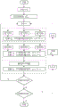
As a further technical limitation, the distributed iterative solution is sequentially performed on the three mixed integer quadratic programming models by using a target cascade analysis algorithm, and the specific process is as follows:
initializing Lagrange term coefficients and target variables, and transmitting initialized data information to a distribution network subproblem mixed integer quadratic programming model and a distribution network subproblem mixed integer quadratic programming model;
solving each sub-problem mixed integer quadratic programming model of the distribution network in parallel, updating response variables and transmitting the response variables to the corresponding sub-problem mixed integer quadratic programming model of the distribution network;
solving each sub-problem mixed integer quadratic programming model of the distribution network in parallel, updating target variables and transmitting the target variables to the corresponding sub-problem mixed integer quadratic programming model of the distribution network;
updating response variables and transmitting the response variables to the transmission network sub-problem mixed integer quadratic programming model, and solving the transmission network sub-problem mixed integer quadratic programming model;
updating target variables and transmitting the target variables to corresponding power distribution network subproblem mixed integer quadratic programming models;
judging inner circulation convergence, if the inner circulation convergence is judged, judging outer circulation convergence, and if the inner circulation convergence is judged, returning to the quadratic programming model for solving the sub-problem and the integral of the gas distribution network;
and judging outer loop convergence, if the outer loop convergence is judged, ending iteration and outputting the optimal distributed collaborative planning scheme of the power distribution-gas network, and otherwise, updating the Lagrangian coefficient loop solution again.
According to some embodiments, a second aspect of the present disclosure provides a distribution-grid distributed collaborative planning system considering grid influence, which adopts the following technical solutions:
a distribution-to-grid distributed collaborative planning system that accounts for grid effects, comprising:
the acquisition module is used for acquiring a typical operation scene of a power distribution-gas network;
the optimization module is used for obtaining an optimal distributed collaborative planning scheme of the power distribution-gas network according to the obtained typical operation scene and a preset power distribution-gas network distributed collaborative planning model;
the power distribution-gas network distributed collaborative planning model comprises a power transmission network sub-problem mixed integer quadratic planning model, a power distribution network sub-problem mixed integer quadratic planning model and a gas distribution network sub-problem mixed integer quadratic planning model, and distributed iterative solution is sequentially carried out on the three mixed integer quadratic planning models by using a target cascade analysis algorithm.
According to some embodiments, a third aspect of the present disclosure provides a computer-readable storage medium, which adopts the following technical solutions:
a computer readable storage medium having stored thereon a program which, when executed by a processor, carries out the steps of the method for distributed collaborative planning of a power distribution-gas grid taking into account grid effects according to the first aspect of the present disclosure.
According to some embodiments, a fourth aspect of the present disclosure provides an electronic device, which adopts the following technical solutions:
an electronic device comprising a memory, a processor and a program stored on the memory and executable on the processor, the processor implementing the steps of the method for distributed collaborative planning of a power distribution-gas grid taking into account grid effects as described in the first aspect of the present disclosure when executing the program.
Compared with the prior art, the beneficial effect of this disclosure is:
the distributed collaborative planning method for the power distribution-gas network considering the influence of the power transmission network, which is provided by the disclosure, realizes collaborative planning of a plurality of power distribution-gas networks connected to the same power transmission network. Compared with the traditional independent planning method, the collaborative planning can fully take the influence of the state of the power transmission network into consideration, and simultaneously, the multiple power distribution-gas networks are subjected to the expansion planning, so that the overall optimal configuration of system resources is realized, and a planning scheme with higher equipment utilization rate and better economy is obtained.
The distributed solving process based on the target cascade analysis algorithm is constructed, the sub-problem of the distribution network and the sub-problem of the transmission network are constructed to decouple the transmission network from the distribution network and the distribution network, the sub-problems of the distribution network and the distribution network can be calculated independently in parallel, and the calculation time is greatly reduced. And secondly, only the target variable t and the response variable r need to be exchanged between the power transmission network and the power distribution network and between the power distribution network and the gas distribution network in the iteration process, so that the privacy of a user is well protected, and the burden of a communication system and an information processor is reduced.
The specific implementation mode is as follows:
the present disclosure is further described with reference to the following drawings and examples.
It should be noted that the following detailed description is exemplary and is intended to provide further explanation of the disclosure. Unless defined otherwise, all technical and scientific terms used herein have the same meaning as commonly understood by one of ordinary skill in the art to which this disclosure belongs.
It is noted that the terminology used herein is for the purpose of describing particular embodiments only and is not intended to be limiting of example embodiments according to the present disclosure. As used herein, the singular forms "a", "an" and "the" are intended to include the plural forms as well, and it should be understood that when the terms "comprises" and/or "comprising" are used in this specification, they specify the presence of stated features, steps, operations, devices, components, and/or combinations thereof, unless the context clearly indicates otherwise.
The embodiments and features of the embodiments in the present disclosure may be combined with each other without conflict.
Example one
The first embodiment of the disclosure introduces a power distribution-gas network distributed collaborative planning method considering the influence of a power transmission network.
The power generation permeability of the distributed renewable energy sources in the power distribution network is improved, and the coupling degree between the power distribution network and the gas distribution network and between the power distribution network and the power transmission network is increased; the embodiment provides a power distribution-gas network distributed collaborative planning system and a method considering the influence of a power transmission network; a distributed solving process based on an ATC algorithm is constructed, and collaborative extension planning is carried out on a plurality of power distribution-gas networks, so that the optimal allocation of resources in the whole system is realized, and the economy of a planning scheme is improved.
A distribution-grid distributed collaborative planning method considering grid effects, as shown in fig. 1, includes the following steps:
acquiring a typical operation scene of a power distribution-gas network;
obtaining an optimal distributed collaborative planning scheme of the power distribution-gas network according to the obtained typical operation scene and a preset power distribution-gas network distributed collaborative planning model;
the power distribution-gas network distributed collaborative planning model comprises a power transmission network sub-problem mixed integer quadratic planning model, a power distribution network sub-problem mixed integer quadratic planning model and a gas distribution network sub-problem mixed integer quadratic planning model, and distributed iterative solution is sequentially carried out on the three mixed integer quadratic planning models by using a target cascade analysis algorithm.
And generating typical operation scenes of normal operation of the power distribution network by adopting a K-means clustering method, and determining the number of the clustering scenes by adopting an elbow method. The elbow method uses the ratio of the intra-class average distance (nSE) and the inter-class average distance (wSE) as an index of clustering error. Setting the true cluster number to k, the elbow method model can be expressed as:
in the formula: deltaiDenotes class i, ks denotes deltaiA middle sample; m isiRepresents deltaiMean value of the medium sample; kn represents deltaiNumber of samples in.
An electric-gas coupling network structure comprising a plurality of distribution networks is shown in fig. 2, and each distribution network and each gas distribution network purchase electric energy and natural gas from a transmission network and a gas transmission network respectively to meet the requirements of electric load and gas load in local areas; the P2G device can convert the surplus electric energy in the distribution network into natural gas, and is a coupling device between the distribution network and the distribution network. The collaborative planning model established in this embodiment simplifies the gas transmission network into a plurality of gas selling units, that is, each distribution network only generates a coupling relationship through the power transmission network.
For distributed solution of the multi-distribution network collaborative planning model, the electro-pneumatic coupling network in fig. 2 needs to be decomposed into a three-layer structure according to a network structure, as shown in fig. 3. In order to decouple each subproblem, shared variables such as active power and the like at adjacent nodes of each subproblem need to be further decomposed into a target variable tpqAnd a response variable rpq. Wherein, tpqFor the shared variable at layer p-1 sub-problem view, rpqIs a shared variable in the view of the p-th layer sub-problem. E.g. t21Sharing variables under the view angle of the layer 1 sub-problem, namely the sub-problem of the power transmission network, and decision variables in the sub-problem of the power transmission network; r is21And sharing variables in the view of the layer 2 sub-problem, namely the power distribution network sub-problem, and decision variables in the power distribution network sub-problem.
Target variable tpqAnd a response variable rpqTo share the formula of the variable among different sub-problems, the consistency constraint formula (4) should be satisfied when each sub-problem is solved independently. The invention relaxes the consistency constraint equation (4) by adding an augmented Lagrangian penalty function term (5) to each sub-problem objective function:
σpq=tpq-rpq=0 (4)
in the formula, σ
pqTo characterize t
pqAnd r
pqA column vector of auxiliary variables of the difference; v. of
pq、w
pqCoefficient column vectors which are respectively a first-order term and a second-order term of the penalty function; symbol
Representing the Hadamard product.
Active power exchanged between different layers is taken as a sharing variable, and the flow from the upper layer to the lower layer is taken as the positive direction of the exchange power. The shared variables between the transmission grid sub-problem and the distribution grid sub-problem can be modeled as:
in the formula (I), the compound is shown in the specification,
and
respectively, in a scene s, on a power transmission system side and a power distribution system side, active power is exchanged between a power transmission system and a qth power distribution system; ns is the typical number of scenes.
The shared variables between the distribution network subproblems and the distribution network subproblems can be modeled as:
in the formula (I), the compound is shown in the specification,
active power exchanged between the qth power distribution system and the gas distribution system through the c P2G device at the power distribution system side and the gas distribution system side respectively under the scene s;
are respectively composed of
A constructed row vector; nc is the number of P2G devices coupled between the qth distribution network and the distribution network.
The sub-problem of the power transmission network only considers the operation process, and the decision variables are the starting and stopping states of the power transmission network generator, the output power and the active power transmitted to each power distribution network in each scene. The optimization target of the power transmission network sub-problem is as follows:
in the formula (f)
11As an objective function of grid sub-problems, including operating costs
And a penalty function pi
11In which the running cost
The system consists of two parts, namely the power generation cost of a generator and the profit obtained by selling power to a power distribution network; h
sThe number of hours a typical scene s occurs in a year; c
G,i(.) is a power generation cost function of the generator at node i; p
G,i,sThe active power output by the generator at the node i in the scene s is obtained; c
eThe unit electricity purchasing cost; a is
G,i、b
G,i、c
G,iRespectively a generator cost function quadratic term, a primary term coefficient and a constant term at a node i; z
on,i,sThe method is characterized in that the starting and stopping states of a generator at a node i in a scene s are represented by 0-1 variables.
The constraint conditions of the power transmission network sub-problem can be expressed as formula (10) to formula (14):
in the formula, P
L,i,sThe active power of the load at the node i in the scene s; p
ij,sThe active power flowing through the line ij in the scene s; theta
i,sIs the phase angle of the voltage at node i in scene s; b
ijIs the susceptance of line ij;
the maximum value of the active output of the generator at the node i is obtained;
maximum value of active power allowed to flow through line ij;
the maximum value of the active power exchanged between the transmission network and the distribution network q is obtained; tb, Tl and Tg are respectively a transmission network node set, a line set and a generator set; d
11The power distribution network serial number set is connected with the power transmission network.
The formula (10) is a node power balance constraint, and the formula (11) is a line direct current power flow constraint; the formula (12), the formula (13) and the formula (14) respectively represent upper and lower limit constraints of the exchange power among the generator, the line and the transmission and distribution network.
The sub-problem of the power distribution network realizes the extension planning of the power distribution network line and the transformer substation, and the decision variables comprise: the method comprises the following steps of power distribution network line extension, new construction variables, substation extension variables, new energy unit output and active power exchanged with a power transmission network and a gas distribution network under each scene. The optimization target of the sub-problems of the power distribution network is as follows:
in the formula (15), f
2qFor the target function of the qth distribution network subproblem, based on investment cost
Running cost
And a penalty function pi
2qThe three parts are formed; the investment cost is reduced to one year, and the investment cost comprises the newly-built feeder line, the extension cost and the substation extension cost; the operating costs include the purchase cost of electricity to the superordinate grid and the profit gained by delivering energy to the distribution grid through the P2G device; the penalty function comprises penalty items caused by inconsistent sharing variables between the transmission network and the distribution network and between the distribution network and the distribution network.
In the formulas (16) and (17), Znf,ij、Zcf,ijThe variable is 0-1, and the variable respectively indicates whether a newly-built and expanded f-type feeder line exists at the power distribution network line ij; zsThe variable is 0-1, and whether the power distribution network substation is expanded to be of an s type or not is represented; cnf、Ccf、CsRespectively representing the new construction and extension cost of the f-type feeder line with unit length and the extension cost of the s-type transformer substation; l isijIs the length of line ij; kappa represents the annual investment cost conversion coefficient of the equipment; r represents annual interest rate; t represents the planning year; and Dl, Df, Ds and Dc respectively represent a line set, an alternative feeder type set, an alternative substation type set and a P2G device set of the q-th power distribution network.
The distribution network sub-problem constraints can be expressed as equations (18) - (28):
Vmin≤Vi,s≤Vmax (26)
in the formula (I), the compound is shown in the specification,
db is a power distribution network node set; db
sThe method comprises the following steps of (1) collecting power distribution network substation nodes, namely nodes connected with a power transmission network; v
i,sRepresenting the voltage magnitude of node i in a typical scenario s; v
refIs the reference node voltage;
respectively representing active power and reactive power flowing through a line ij in a typical scene s;
respectively representing active power generated by a distributed fan and a photovoltaic at a node i in a scene s and active power obtained by a transformer substation from a power transmission network,
is the corresponding reactive power;
represents the real power consumed by the P2G device at node i in scenario s; p
i load、
Respectively representing the active power base value and the reactive power base value of the load at the node i;
respectively representing normalized electric load, photovoltaic maximum output and wind power maximum output in a typical scene s; z
f,ijThe variable is 0-1, and indicates whether the f-type feeder line exists at the planned power distribution network line ij;
respectively representing the maximum capacity of the f-type feeder line and the s-type transformer substation;
for distributing electricityMaximum power of the c coupling node between the network and the distribution network, namely the c P2G device; b
ij,sTo assist with slack variables, when a line is not being constructed at line ij, b
ij,sIs at [ (V)
min-V
max),(V
max-V
min)](ii) auxiliary variables that vary randomly within the range, when the constraint (18) is relaxed; r is
f、x
fRespectively representing the resistance value and the reactance value of the f-type feeder line in unit length; l is
ijRepresents the length of line ij; v
max、V
minRespectively representing the maximum value and the minimum value of the node voltage;
respectively representing whether the line ij has a forward virtual power flow and a reverse virtual power flow.
Equation (18) is a linear Distflow power flow constraint, which represents the relationship between the voltage across the line and the line power flow. The formula (19) and the formula (20) are respectively node active power balance constraint and node reactive power balance constraint. Equation (21) is the auxiliary slack variable bij,sValue range constraint; equation (22) ensures that there is only one type of feeder at line ij and only one type of substation at the substation node. Formulas (23) to (26) are respectively line capacity constraint, transformer substation capacity constraint, new energy station output constraint and node voltage upper and lower limit constraint, and formula (27) is tree topology constraint to ensure that the planned power distribution network is a tree power distribution network. The formula (28) is the upper and lower limit constraint of energy exchange between the distribution network and the distribution network through the P2G device.
The sub-problem of the gas distribution network realizes the expansion planning of the gas distribution network pipeline and the gas distribution station, and the decision variables comprise: the method comprises the following steps of expanding and building pipelines of a gas distribution network, building variables, expanding variables of a gas distribution station, and the amount of natural gas obtained from a gas transmission network and a P2G device under various scenes. The optimization target of the distribution network sub-problem is as follows:
in formula (29), f
3qAs an objective function of the qth sub-problem of the distribution network, in terms of investment cost
Running cost
And a penalty function pi
3qThe three parts are formed; the investment cost is reduced to one year, including the new construction of pipelines, the extension cost and the extension cost of a gas distribution station; the operation cost comprises the electricity purchasing cost generated by the P2G device consuming electric energy and the gas purchasing cost generated by gas purchasing of the upper-level gas transmission network; the penalty function is a penalty item caused by inconsistency of shared variables of the power distribution network and the gas distribution network. In the formula (30), Zn
p,mn、Zc
p,mnThe variable is 0-1, and the variable respectively indicates whether a newly-built and expanded p-type pipeline exists at the mn part of the gas distribution network line; z
gThe variable is 0-1, and indicates whether a gas distribution station of a gas distribution network is expanded to be of a g type; cn
p、Cc
p、C
gRespectively representing the new construction and the extension cost of a p-type pipeline with unit length and the extension cost of a g-type gas distribution station; l is
mnIs the length of the line mn; gl, Gp and Gg respectively represent a line set, an alternative pipeline type set and an alternative gas distribution station type set of a qth gas distribution network; and Dc represents a P2G device set coupled between the qth distribution network and the distribution network.
The distribution network sub-problem constraint conditions can be expressed as formulas (31) to (37):
in the formula (I), the compound is shown in the specification,
gb is a distribution network node set; gb is
gA station node set of a gas distribution station of a gas distribution network is provided;
respectively representing the natural gas flow input by a gas distribution station at a node m and a P2G device in a scene s;
representing the natural gas flow through which the line mn flows in a typical scenario s;
representing the gas load basic value at the node m;
representing the normalized gas load in a typical scene s;
represents the real power consumed by the P2G device at node m in scenario s; ζ represents the conversion efficiency of the P2G apparatus; z
p,mnIs a variable of 0-1, and represents after planningWhether a p-type pipeline exists at the mn position of the gas distribution network line;
respectively representing the maximum flow of the P-type pipeline and the g-type gas distribution station and the maximum power of a P2G device at a node m; l is
mnRepresents the length of the line mn;
respectively representing whether the forward and reverse virtual natural gas flow rates exist in the line mn.
Equation (31) is the node natural gas flow balance constraint. Equation (32) represents the conversion relationship between the active power of the P2G device at node m and the natural gas flow. Equation (33) ensures that there is only one type of conduit at the line mn and only one type of distribution station at the distribution station node; equations (34) - (36) are respectively the pipeline flow constraint, the gas distribution station flow constraint, and the upper and lower power limits of the P2G device. Equation (37) is a tree topology constraint.
The ATC algorithm-based solving process is shown in fig. 4, and the specific process is as follows:
the first step is as follows: setting the number of external cycles L and the number of internal cycles L to zero, namely setting L to be 0 and K to be 0; setting an initial value of a Lagrange coefficient
With initial value of target variable
The second step is that: setting the number of times of the internal circulation K to K +1, and starting the K-th internal circulation;
the third step: solving the sub-problems of each distribution network in parallel and updating response variables
And transmitting to the corresponding distribution network sub-problem;
the fourth step: solving the sub-problems of each distribution network in parallel and updating the target variable
And transmits the result to the corresponding sub-problem of the distribution network to update the response variable
And transmitting to the transmission network;
the fifth step: solving the sub-problem of the transmission network and updating the target variable
And transmitting to the corresponding distribution network sub-problem;
and a sixth step: judging whether an inner loop convergence condition formula (38) is established or not; if the formula (38) is true, executing the seventh step; otherwise, returning to the second step;
in the formula (I), the compound is shown in the specification,
calculating an objective function of the qth sub-problem of the p layer obtained for the nth internal circulation; epsilon
1Is an inner loop convergence gap;
the seventh step: judging whether the outer loop convergence condition formula (39) is simultaneously established or not; if the two distribution networks are simultaneously established, finishing iteration and outputting the distribution network planning schemes; otherwise, executing the eighth step.
In the formula (I), the compound is shown in the specification,
calculating the obtained shared variable difference value for the L-th outer loop; epsilon
2、ε
3The outer loop convergence gap.
Eighth step: and setting the external circulation times L as L + 1. Updating the penalty function coefficient according to the formula (40) and the formula (41)
In the formula, beta is a constant larger than 1 and represents the weight increasing rate of the penalty function; gamma takes a typical value of 0.25.
The ninth step: device for placing
And returning to the second step.
Example two
The second embodiment of the disclosure introduces a power distribution-gas network distributed collaborative planning system considering the influence of a power transmission network.
A distribution-grid distributed collaborative planning system considering grid effects, as shown in fig. 5, includes:
the acquisition module is used for acquiring a typical operation scene of a power distribution-gas network;
the optimization module is used for obtaining an optimal distributed collaborative planning scheme of the power distribution-gas network according to the obtained typical operation scene and a preset power distribution-gas network distributed collaborative planning model;
the power distribution-gas network distributed collaborative planning model comprises a power transmission network sub-problem mixed integer quadratic planning model, a power distribution network sub-problem mixed integer quadratic planning model and a gas distribution network sub-problem mixed integer quadratic planning model, and distributed iterative solution is sequentially carried out on the three mixed integer quadratic planning models by using a target cascade analysis algorithm.
As shown in fig. 6, the grid is a dual-machine six-node system, and three distribution-gas networks and a constant load are connected to the grid. The three power distribution-gas network topology structures to be planned are the same, only the distributed power sources in the power distribution network are different, and only the structure of the No. 1 power distribution-gas network to be planned is shown in detail in the figure. The power distribution network to be planned is a 23-node system, and 4 existing lines are represented by black solid lines; the alternative lines 31 are shown in dotted gray lines. The gas distribution network to be planned is a 30-node system, and 10 existing lines are represented by black solid lines; the alternate route 27 is shown in gray dashed lines.
The detailed steps are the same as those of the distribution-gas network distributed collaborative planning method considering the influence of the power transmission network provided in the first embodiment, and are not described herein again.
EXAMPLE III
A third embodiment of the present disclosure provides a computer-readable storage medium, on which a program is stored, where the program, when executed by a processor, implements the steps in the distribution-grid distributed collaborative planning method considering grid effects according to the first embodiment of the present disclosure.
The detailed steps are the same as those of the distribution-gas network distributed collaborative planning method considering the influence of the power transmission network provided in the first embodiment, and are not described herein again.
Example four
The fourth embodiment of the present disclosure provides an electronic device, which includes a memory, a processor, and a program stored in the memory and executable on the processor, where the processor executes the program to implement the steps in the distribution-grid distributed collaborative planning method considering the influence of the power transmission grid according to the first embodiment of the present disclosure.
The detailed steps are the same as those of the distribution-gas network distributed collaborative planning method considering the influence of the power transmission network provided in the first embodiment, and are not described herein again.
The above description is only a preferred embodiment of the present disclosure and is not intended to limit the present disclosure, and various modifications and changes may be made to the present disclosure by those skilled in the art. Any modification, equivalent replacement, improvement and the like made within the spirit and principle of the present disclosure should be included in the protection scope of the present disclosure.
Although the present disclosure has been described with reference to specific embodiments, it should be understood that the scope of the present disclosure is not limited thereto, and those skilled in the art will appreciate that various modifications and changes can be made without departing from the spirit and scope of the present disclosure.