CN113489117A - Battery management system with hybrid switching devices capable of being expanded in parallel - Google Patents

Battery management system with hybrid switching devices capable of being expanded in parallel Download PDF

Info

Publication number
CN113489117A
CN113489117A CN202111035636.6A CN202111035636A CN113489117A CN 113489117 A CN113489117 A CN 113489117A CN 202111035636 A CN202111035636 A CN 202111035636A CN 113489117 A CN113489117 A CN 113489117A
Authority
CN
China
Prior art keywords
switch
module
battery
branch
controller
Prior art date
Legal status (The legal status is an assumption and is not a legal conclusion. Google has not performed a legal analysis and makes no representation as to the accuracy of the status listed.)
Pending
Application number
CN202111035636.6A
Other languages
Chinese (zh)
Inventor
毛珂
Current Assignee (The listed assignees may be inaccurate. Google has not performed a legal analysis and makes no representation or warranty as to the accuracy of the list.)
Chengdu Uni Link Energy Co ltd
Original Assignee
Chengdu Uni Link Energy Co ltd
Priority date (The priority date is an assumption and is not a legal conclusion. Google has not performed a legal analysis and makes no representation as to the accuracy of the date listed.)
Filing date
Publication date
Application filed by Chengdu Uni Link Energy Co ltd filed Critical Chengdu Uni Link Energy Co ltd
Priority to CN202111035636.6A priority Critical patent/CN113489117A/en
Publication of CN113489117A publication Critical patent/CN113489117A/en
Pending legal-status Critical Current

Links

Images

Classifications

    • HELECTRICITY
    • H02GENERATION; CONVERSION OR DISTRIBUTION OF ELECTRIC POWER
    • H02JELECTRIC POWER NETWORKS; CIRCUIT ARRANGEMENTS OR SYSTEMS FOR SUPPLYING OR DISTRIBUTING ELECTRIC POWER; SYSTEMS FOR STORING ELECTRIC ENERGY
    • H02J7/00Circuit arrangements for charging or discharging batteries or for supplying loads from batteries
    • H02J7/80Circuit arrangements for charging or discharging batteries or for supplying loads from batteries including monitoring or indicating arrangements
    • HELECTRICITY
    • H01ELECTRIC ELEMENTS
    • H01MPROCESSES OR MEANS, e.g. BATTERIES, FOR THE DIRECT CONVERSION OF CHEMICAL ENERGY INTO ELECTRICAL ENERGY
    • H01M10/00Secondary cells; Manufacture thereof
    • H01M10/42Methods or arrangements for servicing or maintenance of secondary cells or secondary half-cells
    • H01M10/4207Methods or arrangements for servicing or maintenance of secondary cells or secondary half-cells for several batteries or cells simultaneously or sequentially
    • HELECTRICITY
    • H01ELECTRIC ELEMENTS
    • H01MPROCESSES OR MEANS, e.g. BATTERIES, FOR THE DIRECT CONVERSION OF CHEMICAL ENERGY INTO ELECTRICAL ENERGY
    • H01M10/00Secondary cells; Manufacture thereof
    • H01M10/42Methods or arrangements for servicing or maintenance of secondary cells or secondary half-cells
    • H01M10/425Structural combination with electronic components, e.g. electronic circuits integrated to the outside of the casing
    • HELECTRICITY
    • H02GENERATION; CONVERSION OR DISTRIBUTION OF ELECTRIC POWER
    • H02HEMERGENCY PROTECTIVE CIRCUIT ARRANGEMENTS
    • H02H7/00Emergency protective circuit arrangements specially adapted for specific types of electric machines or apparatus or for sectionalised protection of cable or line systems, and effecting automatic switching in the event of an undesired change from normal working conditions
    • H02H7/18Emergency protective circuit arrangements specially adapted for specific types of electric machines or apparatus or for sectionalised protection of cable or line systems, and effecting automatic switching in the event of an undesired change from normal working conditions for batteries; for accumulators
    • HELECTRICITY
    • H02GENERATION; CONVERSION OR DISTRIBUTION OF ELECTRIC POWER
    • H02JELECTRIC POWER NETWORKS; CIRCUIT ARRANGEMENTS OR SYSTEMS FOR SUPPLYING OR DISTRIBUTING ELECTRIC POWER; SYSTEMS FOR STORING ELECTRIC ENERGY
    • H02J7/00Circuit arrangements for charging or discharging batteries or for supplying loads from batteries
    • H02J7/40Circuit arrangements for charging or discharging batteries or for supplying loads from batteries characterised by the exchange of charge or discharge related data
    • H02J7/44Circuit arrangements for charging or discharging batteries or for supplying loads from batteries characterised by the exchange of charge or discharge related data between battery management systems and power sources
    • HELECTRICITY
    • H02GENERATION; CONVERSION OR DISTRIBUTION OF ELECTRIC POWER
    • H02JELECTRIC POWER NETWORKS; CIRCUIT ARRANGEMENTS OR SYSTEMS FOR SUPPLYING OR DISTRIBUTING ELECTRIC POWER; SYSTEMS FOR STORING ELECTRIC ENERGY
    • H02J7/00Circuit arrangements for charging or discharging batteries or for supplying loads from batteries
    • H02J7/50Circuit arrangements for charging or discharging batteries or for supplying loads from batteries acting upon multiple batteries simultaneously or sequentially
    • H02J7/52Circuit arrangements for charging or discharging batteries or for supplying loads from batteries acting upon multiple batteries simultaneously or sequentially for charge balancing, e.g. equalisation of charge between batteries
    • H02J7/56Active balancing, e.g. using capacitor-based, inductor-based or DC-DC converters
    • HELECTRICITY
    • H02GENERATION; CONVERSION OR DISTRIBUTION OF ELECTRIC POWER
    • H02JELECTRIC POWER NETWORKS; CIRCUIT ARRANGEMENTS OR SYSTEMS FOR SUPPLYING OR DISTRIBUTING ELECTRIC POWER; SYSTEMS FOR STORING ELECTRIC ENERGY
    • H02J7/00Circuit arrangements for charging or discharging batteries or for supplying loads from batteries
    • H02J7/60Circuit arrangements for charging or discharging batteries or for supplying loads from batteries including safety or protection arrangements
    • H02J7/62Circuit arrangements for charging or discharging batteries or for supplying loads from batteries including safety or protection arrangements against overcurrent
    • HELECTRICITY
    • H02GENERATION; CONVERSION OR DISTRIBUTION OF ELECTRIC POWER
    • H02JELECTRIC POWER NETWORKS; CIRCUIT ARRANGEMENTS OR SYSTEMS FOR SUPPLYING OR DISTRIBUTING ELECTRIC POWER; SYSTEMS FOR STORING ELECTRIC ENERGY
    • H02J7/00Circuit arrangements for charging or discharging batteries or for supplying loads from batteries
    • H02J7/60Circuit arrangements for charging or discharging batteries or for supplying loads from batteries including safety or protection arrangements
    • H02J7/663Circuit arrangements for charging or discharging batteries or for supplying loads from batteries including safety or protection arrangements using battery or load disconnect circuits
    • HELECTRICITY
    • H02GENERATION; CONVERSION OR DISTRIBUTION OF ELECTRIC POWER
    • H02JELECTRIC POWER NETWORKS; CIRCUIT ARRANGEMENTS OR SYSTEMS FOR SUPPLYING OR DISTRIBUTING ELECTRIC POWER; SYSTEMS FOR STORING ELECTRIC ENERGY
    • H02J7/00Circuit arrangements for charging or discharging batteries or for supplying loads from batteries
    • H02J7/80Circuit arrangements for charging or discharging batteries or for supplying loads from batteries including monitoring or indicating arrangements
    • H02J7/82Control of state of charge [SOC]
    • HELECTRICITY
    • H01ELECTRIC ELEMENTS
    • H01MPROCESSES OR MEANS, e.g. BATTERIES, FOR THE DIRECT CONVERSION OF CHEMICAL ENERGY INTO ELECTRICAL ENERGY
    • H01M10/00Secondary cells; Manufacture thereof
    • H01M10/42Methods or arrangements for servicing or maintenance of secondary cells or secondary half-cells
    • H01M10/425Structural combination with electronic components, e.g. electronic circuits integrated to the outside of the casing
    • H01M2010/4271Battery management systems including electronic circuits, e.g. control of current or voltage to keep battery in healthy state, cell balancing
    • HELECTRICITY
    • H01ELECTRIC ELEMENTS
    • H01MPROCESSES OR MEANS, e.g. BATTERIES, FOR THE DIRECT CONVERSION OF CHEMICAL ENERGY INTO ELECTRICAL ENERGY
    • H01M10/00Secondary cells; Manufacture thereof
    • H01M10/42Methods or arrangements for servicing or maintenance of secondary cells or secondary half-cells
    • H01M10/425Structural combination with electronic components, e.g. electronic circuits integrated to the outside of the casing
    • H01M2010/4278Systems for data transfer from batteries, e.g. transfer of battery parameters to a controller, data transferred between battery controller and main controller
    • YGENERAL TAGGING OF NEW TECHNOLOGICAL DEVELOPMENTS; GENERAL TAGGING OF CROSS-SECTIONAL TECHNOLOGIES SPANNING OVER SEVERAL SECTIONS OF THE IPC; TECHNICAL SUBJECTS COVERED BY FORMER USPC CROSS-REFERENCE ART COLLECTIONS [XRACs] AND DIGESTS
    • Y02TECHNOLOGIES OR APPLICATIONS FOR MITIGATION OR ADAPTATION AGAINST CLIMATE CHANGE
    • Y02EREDUCTION OF GREENHOUSE GAS [GHG] EMISSIONS, RELATED TO ENERGY GENERATION, TRANSMISSION OR DISTRIBUTION
    • Y02E60/00Enabling technologies; Technologies with a potential or indirect contribution to GHG emissions mitigation
    • Y02E60/10Energy storage using batteries

Landscapes

  • Engineering & Computer Science (AREA)
  • Power Engineering (AREA)
  • Manufacturing & Machinery (AREA)
  • Chemical & Material Sciences (AREA)
  • Chemical Kinetics & Catalysis (AREA)
  • Electrochemistry (AREA)
  • General Chemical & Material Sciences (AREA)
  • Microelectronics & Electronic Packaging (AREA)
  • Charge And Discharge Circuits For Batteries Or The Like (AREA)
  • Secondary Cells (AREA)

Abstract

本发明公开了一种混合式开关器件可并联扩展的电池管理系统,包括总线控制单元和支线控制单元;总线控制单元包括主控制器和第一开关模组;支线控制单元包括电池模组、第二开关模组、支线控制器和检测模块;支线控制器与主控制器连接,支线控制器将采集到的电池物理信息上传至主控制器;主控制器根据获取的信息向支线控制器下发控制指令。本发明的主控制器获取支线控制器的状态和信号,通过检测采集到的信息进行判断,控制供电总回路的通断状态;同时,支线控制器能够根据检测到的信息通过第二开关模组来控制电池模组的通断状态,使得本发明的电池管理系统具有双重保障,提高了安全性。

Figure 202111035636

The invention discloses a battery management system that can be expanded in parallel with a hybrid switch device, comprising a bus control unit and a branch line control unit; the bus control unit includes a main controller and a first switch module; the branch line control unit includes a battery module, a branch line control unit Two switch modules, branch line controller and detection module; the branch line controller is connected with the main controller, the branch line controller uploads the collected battery physical information to the main controller; the main controller sends the information to the branch line controller according to the acquired information Control instruction. The main controller of the present invention obtains the state and signal of the branch line controller, makes judgment by detecting the collected information, and controls the on-off state of the general power supply circuit; at the same time, the branch line controller can pass the second switch module according to the detected information. To control the on-off state of the battery module, the battery management system of the present invention has double guarantees and improves safety.

Figure 202111035636

Description

Battery management system with hybrid switching devices capable of being expanded in parallel
Technical Field
The invention relates to the technical field of battery management, in particular to a battery management system with hybrid switching devices capable of being expanded in parallel.
Background
As the battery capacity required in the fields of motor homes, yachts, household energy storage and the like is increasingly large, a relatively large current needs to be supported at a relatively low voltage level. For example, the current demand of a 12v power supply system of a motor home can be as high as 300A or more, and the battery system presents a situation where both the capacity and the current demand increase.
In this case, the conventional battery system and the battery management system BMS scheme thereof cannot guarantee high reliability and high safety.
Disclosure of Invention
The invention aims to provide a battery management system with hybrid switching devices capable of being expanded in parallel.
To achieve the above object, in one embodiment of the present invention, a battery management system with hybrid switching devices expandable in parallel is provided, including:
the system comprises a bus control unit and a branch control unit;
the bus control unit comprises a main controller and a first switch module; the main controller is connected with the first switch module and controls the working condition of the first switch module; the first switch module is connected in series to the power supply main loop and used for controlling the on-off state of the power supply main loop;
the first switch module comprises a charging protection switch K1 and a discharging protection switch K2; the main controller cuts off the charging protection switch K1 when charging overcurrent and cuts off the discharging protection switch K2 when discharging overcurrent;
the power supply main loop is connected with a plurality of branch control units in parallel, and each branch control unit comprises a battery module, a second switch module, a branch controller and a detection module;
the second switch module comprises a shunt circuit breaker Bk1, the branch controller controls the on-off state of the second switch module, and the second switch module is connected in series between the battery module and the power supply main loop;
the detection module of the branch control unit is used for detecting and acquiring the physical information of the battery;
the branch controller is connected with the main controller and uploads the acquired physical information of the battery to the main controller; and the main controller sends a control command to the branch controller according to the acquired information to control the working states of the battery module and the second switch module.
In a preferred scheme of the invention, the power supply main loop comprises a positive pole loop and a negative pole loop, and the first switch module is connected in series into the negative pole loop.
In a preferred scheme of the invention, the charging protection switch K1 comprises a charging diode and a charging protection relay Q1, and the discharging protection switch K2 comprises a discharging diode and a discharging protection relay Q2; the charging diode and the discharging diode are connected in series in an opposite direction, the charging protection relay Q1 is connected with the charging diode in parallel, and the discharging protection relay Q2 is connected with the discharging diode in parallel; the main controller is connected with the charging protection relay Q1 and the discharging protection relay Q2 and controls the working conditions of the charging protection relay Q1 and the discharging protection relay Q2.
In the preferred scheme of the invention, the second switch module is provided with a shunt coil and a shunt release matched with the shunt coil, and the branch controller controls the on-off state of the shunt coil; an auxiliary switch S1 is connected in series on the shunt coil, the auxiliary switch S1 is connected with the shunt release, the auxiliary switch S1 is driven to be disconnected when the shunt release is disconnected, and the auxiliary switch S1 is driven to be closed when the shunt release is closed.
In a preferred scheme of the invention, the detection module of the branch line control unit comprises a voltage detection module, a temperature detection module and an electric quantity detection module.
In the preferred scheme of the invention, the branch controller transmits the signal to the main controller through a CAN bus, a 485 bus or a WIFI communication mode.
In the preferred scheme of the invention, the branch control unit comprises a battery equalizer, the battery equalizer is connected with the battery module and the branch controller, and the branch controller controls the equalization mode of the battery equalizer according to the instruction of the main controller.
In a preferred embodiment of the present invention, the balancing method of the spur controller includes:
(1) the main controller acquires the battery physical information of each battery module through the branch controllers, compares the voltage difference among the battery modules, and charges each battery monomer in the battery module with lower voltage through the active equalization circuit, so that the voltage of the whole battery module is gradually increased, and the inter-touch equalization is realized;
(2) and comparing the voltage difference between each battery monomer in each battery module, and charging the battery monomer with lower voltage through the active equalization circuit.
In summary, the invention has the following advantages:
1. the main controller of the invention acquires the states and signals of all branch controllers, judges through detecting the acquired information, and then can control the on-off state of the main power supply loop through the main controller; meanwhile, each branch control unit is provided with a branch controller, and the branch controller can control the on-off state of the battery module through the second switch module according to the detected information, so that the battery management system has double guarantees and improves the safety.
2. The power supply main loop is provided with a first switch module, wherein the first switch module is formed by reversely connecting two MOS body diodes in series to form a charging protection switch K1 and a discharging protection switch K2; the MOS switch has the advantage of high speed, can realize the functions of short-circuit protection and overcurrent protection, and can automatically recover after the fault is relieved.
3. The invention adopts a dual protection structure, thereby realizing dual redundancy, and when malignant accidents such as mos tube breakdown, direct connection fault and relay adhesion are caused, the second switch module adopts a pure physical structure to reliably break the current, thereby ensuring the system safety.
4. The invention can select any battery module to be connected in parallel, thereby realizing the parallel expansion of the battery capacity.
Drawings
FIG. 1 is a circuit diagram of a battery management system in accordance with one embodiment of the present invention; wherein P-is a negative circuit, and P + is a positive circuit; the three parallel long and short lines connected in series represent the battery modules;
FIG. 2 is a diagram illustrating a plurality of branch control units connected in parallel according to an embodiment of the present invention; wherein the first switch module is omitted; wherein B1 is a first branch control unit, B2 is a second branch control unit, and BN is an Nth branch control unit;
FIG. 3 is a schematic diagram of a second switch module incorporated into a power supply main circuit according to an embodiment of the present invention; wherein the branch controller controls the on-off state of the shunt coil.
Detailed Description
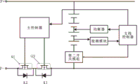
Referring to fig. 1 to 3, the present invention provides a battery management system with hybrid switching devices expandable in parallel, including a bus control unit and a branch control unit.
The bus control unit comprises a main controller and a first switch module; the main controller is connected with the first switch module and controls the working condition of the first switch module; the first switch module is connected in series to the power supply main loop and used for controlling the on-off state of the power supply main loop. And the main controller judges according to the acquired data after obtaining the battery related data from the branch controllers so as to judge whether the battery is abnormal or not and performs related actions after corresponding conditions occur.
The first switch module comprises a charging protection switch K1 and a discharging protection switch K2; the main controller cuts off the charging protection switch K1 when charging overcurrent and cuts off the discharging protection switch K2 when discharging overcurrent, the charging current information can be summarized according to the information uploaded by the branch controllers, and similarly, the discharging current information is judged according to the information uploaded by the branch controllers.
For example, when the battery is overcharged, the charging overheat occurs, when the charging overcurrent occurs, the charging protection switch K1 is turned off, and when the battery is overdischarged, the discharging overheat occurs; therefore, the discharge protection switch K2 is cut off in case of discharge overcurrent and short circuit.
Referring to fig. 2, a power supply main loop is connected in parallel with a plurality of branch control units, and each branch control unit includes a battery module, a second switch module, a branch controller, and a detection module. Each branch control unit is connected in parallel to the power supply main loop, so that the capacity expansion can be realized by increasing the number of the branch control units.
Referring to fig. 3, the second switch module comprises a shunt breaker Bk1, and the branch controller controls the on/off state of the second switch module, and the second switch module is connected in series between the battery module and the main power supply loop. When the branch controller detects that the state of the related battery exceeds the threshold value through the detection module, the connection between the battery module of the branch control unit and the power supply main loop can be cut off by controlling the second switch module. The branch controller can control the connection or disconnection of the battery module and the power supply main loop through the second switch module, so that the safety of a battery system can be protected, and the influence on the whole battery management system caused by the problem of a certain battery module can be avoided; the auxiliary cutting can be performed when the operation such as maintenance is performed.
The second switch module is a shunt circuit breaker Bk1, which comprises an overcurrent protection switch, a thermal protection switch, a leakage protection switch, a shunt release, a shunt coil and an auxiliary switch S1. The overcurrent protection switch, the thermal protection switch and the leakage protection switch can realize the functions of short-circuit protection, high-temperature protection, leakage protection and the like. For example, when a short circuit or temperature rise and current and voltage overrun are found, the switch is automatically switched off. The shunt circuit breaker Bk1 can also be provided with a shunt release on the basis, and the shunt release is realized through a shunt coil so as to achieve other protection purposes.
The shunt circuit breaker Bk1 can be trip-protected in three ways:
(1) the branch controller energizes the shunt coil, and the shunt release triggers tripping;
(2) short-circuit current flows through the shunt circuit breaker Bk1 to trigger the magnetic tripping mechanism, so that short-circuit protection tripping is realized;
(3) when the current through the shunt breaker Bk1 exceeds the rated value, the accumulated heat triggers a thermal trip.
The detection module of the branch control unit is used for detecting and acquiring the physical information of the battery; the branch controller is connected with the main controller, and the branch controller transmits signals to the main controller through a CAN bus, a 485 bus or a WIFI communication mode.
The branch controller uploads the collected physical information of the battery to the main controller; and the main controller sends a control command to the branch controller according to the acquired information to control the working states of the battery module and the second switch module. The detection module of the branch control unit comprises a voltage detection module, a temperature detection module and an electric quantity detection module.
In an embodiment of the present invention, the power supply main circuit includes a positive circuit and a negative circuit, and the first switch module is connected in series to the negative circuit.
In order to implement the present invention, any one of the charge protection switch K1 and the discharge protection switch K2 that can realize charge/discharge protection may be selected.
For example, referring to fig. 2, the charge protection switch K1 includes a charge diode and a charge protection relay Q1, and the discharge protection switch K2 includes a discharge diode and a discharge protection relay Q2; the charging diode and the discharging diode are connected in series in an opposite direction, the charging protection relay Q1 is connected with the charging diode in parallel, and the discharging protection relay Q2 is connected with the discharging diode in parallel; the main controller is connected with the charging protection relay Q1 and the discharging protection relay Q2 and controls the working conditions of the charging protection relay Q1 and the discharging protection relay Q2.
For example, the first switch module is formed by connecting two MOS body diodes in series in reverse to form a charging protection switch K1 and a discharging protection switch K2.
In a specific embodiment of the invention, the second switch module is provided with a shunt coil and a shunt release matched with the shunt coil, and the branch controller controls the on-off state of the shunt coil; an auxiliary switch S1 is connected in series on the shunt opening coil, the auxiliary switch S1 is mechanically connected with the shunt opening release, the shunt opening release drives the auxiliary switch S1 to be opened when being opened, the shunt opening release drives the auxiliary switch S1 to be closed when being manually restored to be closed, the auxiliary switch S1 is used for protecting the shunt opening coil, and the auxiliary switch S1 can be opened after the shunt opening coil is powered off.
Shunt opening coil can not be circular telegram for a long time, otherwise burns out easily, consequently protects through auxiliary switch S1, after shunt opening coil circular telegram, will trigger shunt opening release for second switch module Bk1 disconnection, and then the disconnection of disconnection battery module and power supply total return circuit, however after shunt opening release, if do not have auxiliary switch, shunt opening coil will be circular telegram always this moment, must be burnt out. Therefore, the auxiliary switch is arranged to be linked with the shunt release, so that when the shunt breaker is disconnected, the shunt coil is also disconnected.
The shunt coils need to be independently powered, so that the branch controller controls the input current of the shunt coils, the negative poles of the shunt coils can be connected with a negative pole loop, and an auxiliary switch S1 is connected between the shunt coils and the branch controller in series.
In the embodiment of the invention, the branch control unit comprises a battery equalizer, the battery equalizer is connected with the battery module and the branch controller, and the branch controller controls the equalization mode of the battery equalizer according to the instruction of the main controller.
The battery equalizer is an outsourced electronic component, is a HA01 battery equalizer and is used for keeping the charge-discharge balance among storage batteries in a storage battery pack connected in series.
The balancing mode of the branch controller comprises the following steps:
(1) the main controller acquires the battery physical information of each battery module through the branch controllers, compares the voltage difference among the battery modules, and charges each battery monomer in the battery module with lower voltage through the active equalization circuit, so that the voltage of the whole battery module is gradually increased, and the inter-touch equalization is realized;
(2) and comparing the voltage difference between each battery monomer in each battery module, and charging the battery monomer with lower voltage through the active equalization circuit.
While the present invention has been described in detail with reference to the illustrated embodiments, it should not be construed as limited to the scope of the present patent. Various modifications and changes may be made by those skilled in the art without inventive step within the scope of the appended claims.

Claims (7)

1. A hybrid switching device parallel scalable battery management system, comprising:
the system comprises a bus control unit and a branch control unit;
the bus control unit comprises a main controller and a first switch module; the main controller is connected with the first switch module and controls the working condition of the first switch module; the first switch module is connected in series to the power supply main loop and used for controlling the on-off state of the power supply main loop;
the first switch module comprises a charging protection switch K1 and a discharging protection switch K2; the main controller cuts off the charging protection switch K1 when charging overcurrent and cuts off the discharging protection switch K2 when discharging overcurrent;
the power supply main loop is connected with a plurality of branch control units in parallel, and each branch control unit comprises a battery module, a second switch module, a branch controller and a detection module;
the second switch module comprises a shunt circuit breaker Bk1, the branch controller controls the on-off state of the second switch module, and the second switch module is connected in series between the battery module and the power supply main loop;
the detection module of the branch control unit is used for detecting and acquiring physical information of the battery;
the branch controller is connected with the main controller and uploads the collected physical information of the battery to the main controller; and the main controller sends a control command to the branch controller according to the acquired information to control the working states of the battery module and the second switch module.
2. A hybrid switching device parallel scalable battery management system as recited in claim 1, wherein: the power supply main loop comprises a positive pole loop and a negative pole loop, and the first switch module is connected into the negative pole loop in series.
3. A hybrid switching device parallel scalable battery management system as recited in claim 1, wherein: the charging protection switch K1 comprises a charging diode and a charging protection relay Q1, and the discharging protection switch K2 comprises a discharging diode and a discharging protection relay Q2; the charging diode and the discharging diode are connected in series in an opposite direction, the charging protection relay Q1 is connected with the charging diode in parallel, and the discharging protection relay Q2 is connected with the discharging diode in parallel; the main controller is connected with the charging protection relay Q1 and the discharging protection relay Q2 and controls the working conditions of the charging protection relay Q1 and the discharging protection relay Q2.
4. A hybrid switching device parallel scalable battery management system as recited in claim 1, wherein: the second switch module is provided with a shunt coil and a shunt release matched with the shunt coil, and the branch controller controls the on-off state of the shunt coil; an auxiliary switch S1 is connected in series on the shunt coil, the auxiliary switch S1 is connected with the shunt release, the auxiliary switch S1 is driven to be disconnected when the shunt release is disconnected, and the auxiliary switch S1 is driven to be closed when the shunt release is closed.
5. A hybrid switching device parallel scalable battery management system as recited in claim 1, wherein: the detection module of the branch control unit comprises a voltage detection module, a temperature detection module and an electric quantity detection module.
6. A hybrid switching device parallel scalable battery management system as recited in claim 1, wherein: and the branch controller transmits signals to the main controller through a CAN bus or a 485 bus.
7. A hybrid switching device parallel scalable battery management system as recited in claim 1, wherein: the branch control unit comprises a battery equalizer, the battery equalizer is connected with the battery module and the branch controller, and the branch controller controls the battery equalizer according to the instruction of the main controller.
CN202111035636.6A 2021-09-06 2021-09-06 Battery management system with hybrid switching devices capable of being expanded in parallel Pending CN113489117A (en)

Priority Applications (1)

Application Number Priority Date Filing Date Title
CN202111035636.6A CN113489117A (en) 2021-09-06 2021-09-06 Battery management system with hybrid switching devices capable of being expanded in parallel

Applications Claiming Priority (1)

Application Number Priority Date Filing Date Title
CN202111035636.6A CN113489117A (en) 2021-09-06 2021-09-06 Battery management system with hybrid switching devices capable of being expanded in parallel

Publications (1)

Publication Number Publication Date
CN113489117A true CN113489117A (en) 2021-10-08

Family

ID=77947201

Family Applications (1)

Application Number Title Priority Date Filing Date
CN202111035636.6A Pending CN113489117A (en) 2021-09-06 2021-09-06 Battery management system with hybrid switching devices capable of being expanded in parallel

Country Status (1)

Country Link
CN (1) CN113489117A (en)

Cited By (1)

* Cited by examiner, † Cited by third party
Publication number Priority date Publication date Assignee Title
CN118928042A (en) * 2024-08-30 2024-11-12 比亚迪股份有限公司 Battery systems and vehicles

Citations (7)

* Cited by examiner, † Cited by third party
Publication number Priority date Publication date Assignee Title
CN101924377A (en) * 2009-06-15 2010-12-22 上海市电力公司 A distributed modular DC charging system for electric vehicles
CN102761148A (en) * 2011-04-29 2012-10-31 比亚迪股份有限公司 Battery pack management system
CN104104137A (en) * 2014-07-23 2014-10-15 山东大学 Lithium iron phosphate power battery management system and management method
CN106486976A (en) * 2016-11-23 2017-03-08 宇龙计算机通信科技(深圳)有限公司 Battery protecting apparatus and battery protecting method
CN107658919A (en) * 2015-08-03 2018-02-02 成都宇能通能源开发有限公司 A kind of battery pack parallel circuit
CN111585330A (en) * 2020-07-02 2020-08-25 深圳市欧力普能源与自动化技术有限公司 A high-current lithium battery protection device and battery protection method
CN113315201A (en) * 2021-06-02 2021-08-27 清华大学 Battery energy storage system

Patent Citations (7)

* Cited by examiner, † Cited by third party
Publication number Priority date Publication date Assignee Title
CN101924377A (en) * 2009-06-15 2010-12-22 上海市电力公司 A distributed modular DC charging system for electric vehicles
CN102761148A (en) * 2011-04-29 2012-10-31 比亚迪股份有限公司 Battery pack management system
CN104104137A (en) * 2014-07-23 2014-10-15 山东大学 Lithium iron phosphate power battery management system and management method
CN107658919A (en) * 2015-08-03 2018-02-02 成都宇能通能源开发有限公司 A kind of battery pack parallel circuit
CN106486976A (en) * 2016-11-23 2017-03-08 宇龙计算机通信科技(深圳)有限公司 Battery protecting apparatus and battery protecting method
CN111585330A (en) * 2020-07-02 2020-08-25 深圳市欧力普能源与自动化技术有限公司 A high-current lithium battery protection device and battery protection method
CN113315201A (en) * 2021-06-02 2021-08-27 清华大学 Battery energy storage system

Cited By (2)

* Cited by examiner, † Cited by third party
Publication number Priority date Publication date Assignee Title
CN118928042A (en) * 2024-08-30 2024-11-12 比亚迪股份有限公司 Battery systems and vehicles
CN118928042B (en) * 2024-08-30 2025-11-04 比亚迪股份有限公司 Battery systems and vehicles

Similar Documents

Publication Publication Date Title
US11677232B2 (en) Quick battery disconnect system for high current circuits
CN102457084B (en) Battery fault tolerant architecture for cell failure modes parallel bypass circuit
RU2500062C2 (en) High-speed switching device for high-power accumulator battery in isolated dc circuit
EP2602904B1 (en) Secondary battery pack connection control method, power storage system, and secondary battery pack
CN110571883B (en) Lithium battery charging current limiting system
CN103972990B (en) Lithium iron phosphate battery energy storage system
JPWO2012050210A1 (en) Power storage system and control device
KR101698401B1 (en) Energy storing device with cooling elements, and method for cooling energy storing cells
JP2001309563A (en) Building power supply system and battery device
KR20150119905A (en) Detection and prevention of short formation in battery packs
CN112701745A (en) Lithium battery management system and control method thereof
CN110932357A (en) Energy storage device
CN109228874A (en) A kind of power battery protection system and electric car
AU2023209311A1 (en) Energy storage system
JP6397673B2 (en) Control method of power supply control device
CN113612288A (en) A Dual Redundancy and High Reliability Battery Management System
CN113489117A (en) Battery management system with hybrid switching devices capable of being expanded in parallel
TWI233228B (en) Secondary batteries having a bypass resistance and the protective method of the secondary battery
CN108155695B (en) Parallel charging and discharging system and protection method for single battery cabinet group
CN111095719A (en) battery device
JP2007110887A (en) Battery charge / discharge switch system
CN115411824A (en) Power supply protection method and device, power supply and electric energy device
CN216162436U (en) Battery management system with dual redundancies and high reliability
CN116683574A (en) Energy storage device and method for controlling disconnection of energy storage device
CN223378924U (en) Pre-charging circuit and energy storage device

Legal Events

Date Code Title Description
PB01 Publication
PB01 Publication
SE01 Entry into force of request for substantive examination
RJ01 Rejection of invention patent application after publication

Application publication date: 20211008