CN113487510A - Method, system and equipment for detecting needle point position for automatic liquid preparation of robot - Google Patents
Method, system and equipment for detecting needle point position for automatic liquid preparation of robot Download PDFInfo
- Publication number
- CN113487510A CN113487510A CN202110803839.9A CN202110803839A CN113487510A CN 113487510 A CN113487510 A CN 113487510A CN 202110803839 A CN202110803839 A CN 202110803839A CN 113487510 A CN113487510 A CN 113487510A
- Authority
- CN
- China
- Prior art keywords
- world
- needle
- image
- coordinates
- roi
- Prior art date
- Legal status (The legal status is an assumption and is not a legal conclusion. Google has not performed a legal analysis and makes no representation as to the accuracy of the status listed.)
- Pending
Links
Images


Classifications
-
- G—PHYSICS
- G06—COMPUTING OR CALCULATING; COUNTING
- G06T—IMAGE DATA PROCESSING OR GENERATION, IN GENERAL
- G06T5/00—Image enhancement or restoration
- G06T5/70—Denoising; Smoothing
-
- G—PHYSICS
- G06—COMPUTING OR CALCULATING; COUNTING
- G06T—IMAGE DATA PROCESSING OR GENERATION, IN GENERAL
- G06T5/00—Image enhancement or restoration
- G06T5/20—Image enhancement or restoration using local operators
-
- G—PHYSICS
- G06—COMPUTING OR CALCULATING; COUNTING
- G06T—IMAGE DATA PROCESSING OR GENERATION, IN GENERAL
- G06T5/00—Image enhancement or restoration
- G06T5/40—Image enhancement or restoration using histogram techniques
-
- G—PHYSICS
- G06—COMPUTING OR CALCULATING; COUNTING
- G06T—IMAGE DATA PROCESSING OR GENERATION, IN GENERAL
- G06T7/00—Image analysis
- G06T7/10—Segmentation; Edge detection
- G06T7/11—Region-based segmentation
-
- G—PHYSICS
- G06—COMPUTING OR CALCULATING; COUNTING
- G06T—IMAGE DATA PROCESSING OR GENERATION, IN GENERAL
- G06T7/00—Image analysis
- G06T7/10—Segmentation; Edge detection
- G06T7/13—Edge detection
-
- G—PHYSICS
- G06—COMPUTING OR CALCULATING; COUNTING
- G06T—IMAGE DATA PROCESSING OR GENERATION, IN GENERAL
- G06T7/00—Image analysis
- G06T7/70—Determining position or orientation of objects or cameras
-
- G—PHYSICS
- G06—COMPUTING OR CALCULATING; COUNTING
- G06T—IMAGE DATA PROCESSING OR GENERATION, IN GENERAL
- G06T7/00—Image analysis
- G06T7/80—Analysis of captured images to determine intrinsic or extrinsic camera parameters, i.e. camera calibration
Landscapes
- Engineering & Computer Science (AREA)
- Physics & Mathematics (AREA)
- General Physics & Mathematics (AREA)
- Theoretical Computer Science (AREA)
- Computer Vision & Pattern Recognition (AREA)
- Length Measuring Devices By Optical Means (AREA)
Abstract
本发明属于图像检测领域,具体涉及一种用于机器人自动配液的针尖位置检测方法、系统、设备,旨在解决现有的配液机器人在配液的过程中,因无法确定针头位置而对机械臂进行正确引导,造成针头对西林瓶瓶口扎偏,进而导致配液效率较低甚至配液失败的问题。本方法包括采集待检测的针头图像;对图像进行预处理;提取图像的ROI区域;通过边缘检测方法获取ROI区域中针头的边缘轮廓,并通过角点检测确定针尖的位置,得到针尖的像素坐标;结合两个不同方位的针尖的像素坐标,通过预设第一位姿求解方法得到针尖对应的世界三维坐标;根据获取的世界三维坐标进行配液。本发明降低了针头的扎取误差,提高了配液机器人的配液效率以及准确性。

The invention belongs to the field of image detection, and in particular relates to a needle tip position detection method, system and equipment for automatic liquid dispensing by a robot. The correct guidance of the robotic arm causes the needle to stick to the mouth of the vial, which leads to the problem of low dispensing efficiency or even failure of dispensing. The method includes collecting the image of the needle to be detected; preprocessing the image; extracting the ROI area of the image; obtaining the edge contour of the needle in the ROI area by an edge detection method, and determining the position of the needle tip through corner point detection to obtain the pixel coordinates of the needle tip ; Combining the pixel coordinates of the needle tips in two different orientations, the world three-dimensional coordinates corresponding to the needle tip are obtained by the preset first pose solution method; the liquid is dispensed according to the obtained world three-dimensional coordinates. The invention reduces the needle sticking error and improves the liquid dispensing efficiency and accuracy of the liquid dispensing robot.
Description
技术领域technical field
本发明属于图像检测领域,具体涉及一种用于机器人自动配液的针尖位置检测方法、系统、设备。The invention belongs to the field of image detection, and in particular relates to a needle tip position detection method, system and equipment for automatic liquid dispensing by a robot.
背景技术Background technique
在配液机器人中,针筒扎向西林瓶、安瓿瓶、输液袋等药品是必要的一个过程。但市面上的针管规格种类繁多,针头种类也各有不同,并且由于普通医用针筒与针尖的材质较软,导致在机械臂夹取甚至是自然状态下,针头存在扭曲变形的情况,很容易在扎取西林瓶时产生误差。而西林瓶可扎取的瓶口直径在1-2mm之间,这就导致机械臂携针管在扎向西林瓶的时候,非常容易扎偏,取液不成功。目前国内外的配液机器人,例如深圳的卫邦公司的WEINAS,大都是采用特制的某种针管抽取药液。这种针管作为医疗耗材,势必增加了医院及患者不必要的医疗成本。基于此,本发明提出了一种用于机器人自动配液的针尖位置检测方法。In the dispensing robot, it is a necessary process for the syringe to pierce the medicines such as vials, ampoules, and infusion bags. However, there are many types of needles on the market, and the types of needles are also different. Moreover, due to the soft materials of ordinary medical syringes and needle tips, the needles may be twisted and deformed under the grip of the robotic arm or even in a natural state, which is very easy. Errors occurred when taking vials. The diameter of the bottle mouth that can be pierced from the vial is between 1-2mm, which leads to the fact that when the robotic arm carries the needle tube, it is very easy to pierce the vial, and the liquid extraction is unsuccessful. At present, liquid dispensing robots at home and abroad, such as WEINAS of Weibang Company in Shenzhen, mostly use a special needle tube to extract liquid medicine. As a medical consumable, this kind of needle tube is bound to increase unnecessary medical costs for hospitals and patients. Based on this, the present invention proposes a needle tip position detection method for automatic liquid dispensing by a robot.
发明内容SUMMARY OF THE INVENTION
为了解决现有技术中的上述问题,即为了解决现有的配液机器人在配液的过程中,因无法确定针头位置而对机械臂进行正确引导,造成针头对西林瓶瓶口扎偏,进而导致配液效率较低甚至配液失败的问题,本发明第一方面,提出了一种用于机器人自动配液的针尖位置检测方法,该方法包括:In order to solve the above problems in the prior art, that is, in order to solve the problem that the existing liquid dispensing robot can not determine the position of the needle during the dispensing process, the robot arm can be correctly guided, causing the needle to stick to the mouth of the vial, and then In the first aspect of the present invention, a method for detecting the position of a needle tip for automatic liquid dispensing by a robot is proposed, which includes:
S10,通过两个不同方位的相机在设定颜色种类光源以及设定光源照明方向下采集待检测的针头图像,作为输入图像;S10, collecting the image of the needle to be detected under the setting of the color type light source and the setting of the lighting direction of the light source through two cameras in different orientations, as an input image;
S20,对所述输入图像进行预处理,得到预处理图像;所述预处理包括去噪、二值化以及直方图均衡化处理;S20, preprocessing the input image to obtain a preprocessing image; the preprocessing includes denoising, binarization, and histogram equalization;
S30,采用预设的基于角点的ROI提取方法提取所述预处理图像中的ROI区域;S30, using a preset corner-based ROI extraction method to extract the ROI region in the preprocessed image;
S40,通过边缘检测方法获取所述ROI区域中针头的边缘轮廓,并通过角点检测确定针尖的位置,进而得到针尖的像素坐标;S40, obtain the edge contour of the needle tip in the ROI area through an edge detection method, and determine the position of the needle tip through corner point detection, and then obtain the pixel coordinates of the needle tip;
S50,结合两个不同方位的针尖的像素坐标,通过预设第一位姿求解方法得到针尖对应的世界三维坐标;所述第一位姿求解方法为根据两幅图像的位姿结果求解像素点的世界坐标的方法;S50, combining the pixel coordinates of the needle tips in two different orientations, obtain the three-dimensional world coordinates corresponding to the needle tip through a preset first pose solution method; the first pose solution method is to solve the pixel points according to the pose results of the two images method of world coordinates;
S60,计算步骤S50获取的世界三维坐标与机器人在开始配液前的计算的标准世界三维坐标的误差,并根据该误差纠正步骤S50获取的世界三维坐标,进而机器人基于纠正后的世界三维坐标进行配液。S60, calculating the error between the world three-dimensional coordinates obtained in step S50 and the standard world three-dimensional coordinates calculated by the robot before starting the liquid dispensing, and correcting the world three-dimensional coordinates obtained in step S50 according to the error, and then the robot performs the correction based on the corrected world three-dimensional coordinates. Dosing.
在一些优选的实施方式中,在步骤S10之前还包括标定板规格的选取、相机内外参标定的步骤:In some preferred embodiments, before step S10, it also includes the steps of selecting the specification of the calibration board and calibrating the internal and external parameters of the camera:
选取行为偶数列为奇数或行为奇数列为偶数的棋盘格作为标定板,且当相机采集到清晰的标定板图像时标定板的面积至少是可用像素面积的一半;所述可用像素面积为采集的整张标定板图像的像素面积;Select a checkerboard with an even-numbered column as an odd number or an odd-numbered column with an even number as the calibration board, and when the camera collects a clear calibration board image, the area of the calibration board is at least half of the available pixel area; the available pixel area is the collected pixel area. The pixel area of the entire calibration plate image;
选取了标定板的规格后,基于世界坐标系、相机坐标系、像素坐标系之间的转换关系,利用Opencv进行相机内参和外参标定;After selecting the specifications of the calibration board, based on the conversion relationship between the world coordinate system, the camera coordinate system, and the pixel coordinate system, use Opencv to calibrate the camera's internal and external parameters;
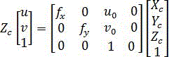
其中,世界坐标系、相机坐标系、像素坐标系之间的转换关系为:Among them, the conversion relationship between the world coordinate system, the camera coordinate system, and the pixel coordinate system is:


其中,


在一些优选的实施方式中,所述设定颜色种类光源以及设定光源照明方向为:In some preferred embodiments, the setting of the color type light source and the setting of the lighting direction of the light source are:
所述设定颜色种类光源为红色光源;The set color type light source is a red light source;
所述设定光源照明方向为背向照明。The set light source lighting direction is back lighting.
在一些优选的实施方式中,“通过预设的基于角点的ROI提取方法提取所述预处理图像中的ROI区域”,其方法为:In some preferred embodiments, "the ROI region in the preprocessed image is extracted by a preset corner-based ROI extraction method", and the method is:
通过角点检测函数对预处理图像进行角点检测,并将所有角点对应的最小外接矩形,作为ROI区域。Corner detection is performed on the preprocessed image through the corner detection function, and the minimum circumscribed rectangle corresponding to all corners is used as the ROI area.
在一些优选的实施方式中,所述边缘检测方法Canny算子边缘检测方法。In some preferred embodiments, the edge detection method is a Canny operator edge detection method.
在一些优选的实施方式中,“通过边缘检测方法获取所述ROI区域中针头的边缘轮廓,并通过角点检测确定针尖的位置”,其方法为:In some preferred embodiments, "acquiring the edge contour of the needle in the ROI area by an edge detection method, and determining the position of the needle tip by detecting a corner point", the method is:
通过边缘检测方法获取所述ROI区域中针头的边缘轮廓;Obtain the edge contour of the needle in the ROI area by an edge detection method;
提取边缘轮廓中的竖直线,并计算水平方向竖直线之间的最大距离;Extract the vertical lines in the edge contour, and calculate the maximum distance between the vertical lines in the horizontal direction;
判断所述最大距离是否大于设定的距离阈值,若大于,则将该水平方向以上的ROI区域删除;Determine whether the maximum distance is greater than the set distance threshold, and if it is greater, delete the ROI area above the horizontal direction;
提取未删除的ROI区域中的竖直线并进行角点检测,将未删除的ROI区域中最长竖直线的最下方的角点作为针尖的位置。Extract the vertical line in the undeleted ROI area and perform corner detection, and use the bottom corner of the longest vertical line in the undeleted ROI area as the position of the needle tip.
在一些优选的实施方式中,所述第一位姿求解方法中像素点的世界三维坐标为两直线的最近点坐标的中点。In some preferred embodiments, the world three-dimensional coordinate of the pixel point in the first pose solution method is the midpoint of the coordinates of the closest points of the two straight lines.
本发明的第二方面,提出了一种用于机器人自动配液的针尖位置检测系统,该系统包括:图像获取模块、预处理模块、ROI区域提取模块、检测模块、世界三维坐标求解模块、配液模块;In the second aspect of the present invention, a needle tip position detection system for automatic liquid dispensing by a robot is proposed. The system includes: an image acquisition module, a preprocessing module, an ROI region extraction module, a detection module, a world three-dimensional coordinate solution module, and a configuration module. liquid module;
所述图像获取模块,配置为通过两个不同方位的相机在设定颜色种类光源以及设定光源照明方向下采集待检测的针头图像,作为输入图像;The image acquisition module is configured to collect the image of the needle to be detected as the input image through two cameras in different orientations under the set color type light source and the set light source illumination direction;
所述预处理模块,配置为对所述输入图像进行预处理,得到预处理图像;所述预处理包括去噪、二值化以及直方图均衡化处理;The preprocessing module is configured to preprocess the input image to obtain a preprocessed image; the preprocessing includes denoising, binarization and histogram equalization;
所述ROI区域提取模块,配置为采用预设的基于角点的ROI提取方法提取所述预处理图像中的ROI区域;The ROI region extraction module is configured to use a preset corner-based ROI extraction method to extract the ROI region in the preprocessed image;
所述检测模块,配置为通过边缘检测方法获取所述ROI区域中针头的边缘轮廓,并通过角点检测确定针尖的位置,进而得到针尖的像素坐标;The detection module is configured to obtain the edge contour of the needle tip in the ROI area through an edge detection method, and determine the position of the needle tip through corner detection, thereby obtaining the pixel coordinates of the needle tip;
所述世界三维坐标求解模块,配置为结合两个不同方位的针尖的像素坐标,通过预设第一位姿求解方法得到针尖对应的世界三维坐标;所述第一位姿求解方法为根据两幅图像的位姿结果求解像素点的世界坐标的方法;The world three-dimensional coordinate solving module is configured to combine the pixel coordinates of the needle tips in two different orientations, and obtain the world three-dimensional coordinates corresponding to the needle tip through a preset first pose solution method; the first pose solution method is based on two images. The method of solving the world coordinate of the pixel point from the pose result of the image;
所述配液模块,配置为计算世界三维坐标求解模块获取的世界三维坐标与机器人在开始配液前的计算的标准世界三维坐标的误差,并根据该误差纠正世界三维坐标求解模块获取的世界三维坐标,进而机器人基于纠正后的世界三维坐标进行配液。The liquid dispensing module is configured to calculate the error between the world three-dimensional coordinates obtained by the world three-dimensional coordinate solving module and the standard world three-dimensional coordinates calculated by the robot before starting liquid dispensing, and correct the world three-dimensional coordinates obtained by the world three-dimensional coordinate solving module according to the error. coordinates, and then the robot dispenses liquid based on the corrected three-dimensional coordinates of the world.
本发明的第三方面,提出了一种电子设备,至少一个处理器;以及与至少一个所述处理器通信连接的存储器;其中,所述存储器存储有可被所述处理器执行的指令,所述指令用于被所述处理器执行以实现权利要求上述的用于机器人自动配液的针尖位置检测方法。A third aspect of the present invention provides an electronic device, at least one processor; and a memory communicatively connected to at least one of the processors; wherein, the memory stores instructions executable by the processor, The instructions are used to be executed by the processor to implement the needle tip position detection method for automatic liquid dispensing by a robot as claimed in the preceding claims.
本发明的第四方面,提出了一种计算机可读存储介质,所述计算机可读存储介质存储有计算机指令,所述计算机指令用于被所述计算机执行以实现权利要求上述的用于机器人自动配液的针尖位置检测方法。In a fourth aspect of the present invention, a computer-readable storage medium is provided, where computer instructions are stored in the computer-readable storage medium, and the computer instructions are used to be executed by the computer to realize the above-mentioned automatic application for robots in the claims. A method for detecting the position of the needle tip for liquid dispensing.
本发明的有益效果:Beneficial effects of the present invention:
本发明降低了针头的扎取误差,提高了配液机器人的配液效率以及准确性。The invention reduces the needle sticking error and improves the liquid dispensing efficiency and accuracy of the liquid dispensing robot.
本发明在完成针尖位置的检测后,计算出弯曲的针尖相较于正常扎取的针尖的位置偏差,为机器人机械手在扎取药瓶提供引导性数据,正确精准地抽取液体,为整个机器人系统准确而有序地运行提供强有力的保证。从而实现节约人力,节约医疗耗材,剂量精确的全自动配液过程。After the detection of the position of the needle tip is completed, the present invention calculates the position deviation of the curved needle tip compared with the needle tip that is normally plucked, so as to provide guiding data for the robot manipulator to pluck the medicine bottle, extract the liquid correctly and accurately, and provide the whole robot system with guiding data. Accurate and orderly operation provides a strong guarantee. So as to save manpower, save medical consumables, and achieve a fully automatic liquid dispensing process with accurate dosage.
附图说明Description of drawings
通过阅读参照以下附图所做的对非限制性实施例所做的详细描述,本申请的其他特征、目的和优点将会变得更明显。Other features, objects and advantages of the present application will become more apparent upon reading the detailed description of non-limiting embodiments taken with reference to the following drawings.
图1是本发明一种实施例的用于机器人自动配液的针尖位置检测方法的流程示意图;1 is a schematic flowchart of a needle tip position detection method for automatic liquid dispensing by a robot according to an embodiment of the present invention;
图2是本发明一种实施例的用于机器人自动配液的针尖位置检测系统的框架示意图;2 is a schematic diagram of the frame of a needle tip position detection system for automatic liquid dispensing by a robot according to an embodiment of the present invention;
图3是本发明一种实施例的针尖位置纠正的简略流程示意图;3 is a schematic flow chart of a needle tip position correction according to an embodiment of the present invention;
图4是本发明一种实施例的针尖位置确定的流程示意图;FIG. 4 is a schematic flow chart of needle tip position determination according to an embodiment of the present invention;
图5(a)是本发明一种实施例的相机内外参标定的流程示意图;FIG. 5( a ) is a schematic flowchart of the calibration of internal and external parameters of a camera according to an embodiment of the present invention;
图5(b)是本发明一种实施例的两个相机分别拍摄的标定版的示意图;Fig. 5(b) is a schematic diagram of a calibration plate shot by two cameras respectively according to an embodiment of the present invention;
图6是本发明一种实施例的前向照明和背向照明的示意图;6 is a schematic diagram of forward lighting and back lighting according to an embodiment of the present invention;
图7(a)是本发明一种实施例的去噪、直方图均衡化后的针头图像的示意图;Figure 7(a) is a schematic diagram of a needle image after denoising and histogram equalization according to an embodiment of the present invention;
图7(b)是本发明一种实施例的二值化后的针头图像的示意图;Figure 7(b) is a schematic diagram of a binarized needle image according to an embodiment of the present invention;
图7(c)是本发明一种实施例的提取的ROI区域的示意图;Fig. 7(c) is a schematic diagram of an extracted ROI region according to an embodiment of the present invention;
图8(a)是本发明一种实施例的边缘检测后的感兴趣区域的示意图;FIG. 8( a ) is a schematic diagram of a region of interest after edge detection according to an embodiment of the present invention;
图8(b)是本发明一种实施例的提取边缘检测后的感兴趣区域中的竖直线的示意图;FIG. 8( b ) is a schematic diagram of extracting vertical lines in the region of interest after edge detection according to an embodiment of the present invention;
图8(c)是本发明一种实施例的缩小范围的边缘图像的示意图;FIG. 8( c ) is a schematic diagram of a reduced-range edge image according to an embodiment of the present invention;
图8(d)是本发明一种实施例的检测到的针尖位置的示意图;Figure 8(d) is a schematic diagram of the detected needle tip position according to an embodiment of the present invention;
图9(a)是本发明一种实施例的由两相机求公共点的坐标原理示意图;Fig. 9(a) is a schematic diagram of the coordinate principle of finding a common point by two cameras according to an embodiment of the present invention;
图9(b)是本发明一种实施例的点
图9(c)是本发明一种实施例的两直线角点的示意图;Fig. 9(c) is a schematic diagram of two straight line corner points according to an embodiment of the present invention;
图10是本发明一种实施例的适于用来实现本申请实施例的电子设备的计算机系统的结构示意图。FIG. 10 is a schematic structural diagram of a computer system suitable for implementing the electronic device of the embodiment of the present application according to an embodiment of the present invention.
具体实施方式Detailed ways
为使本发明的目的、技术方案和优点更加清楚,下面将结合附图对本发明实施例中的技术方案进行清楚、完整地描述,显然,所描述的实施例是本发明一部分实施例,而不是全部的实施例。基于本发明中的实施例,本领域普通技术人员在没有做出创造性劳动前提下所获得的所有其他实施例,都属于本发明保护的范围。In order to make the objectives, technical solutions and advantages of the present invention clearer, the technical solutions in the embodiments of the present invention will be clearly and completely described below with reference to the accompanying drawings. Obviously, the described embodiments are part of the embodiments of the present invention, not All examples. Based on the embodiments of the present invention, all other embodiments obtained by those of ordinary skill in the art without creative efforts shall fall within the protection scope of the present invention.
下面结合附图和实施例对本申请作进一步的详细说明。可以理解的是,此处所描述的具体实施例仅用于解释相关发明,而非对该发明的限定。另外还需要说明的是,为了便于描述,附图中仅示出了与有关发明相关的部分。The present application will be further described in detail below with reference to the accompanying drawings and embodiments. It should be understood that the specific embodiments described herein are only used to explain the related invention, but not to limit the invention. In addition, it should be noted that, for the convenience of description, only the parts related to the related invention are shown in the drawings.
需要说明的是,在不冲突的情况下,本申请中的实施例及实施例中的特征可以相互组合。It should be noted that the embodiments in the present application and the features of the embodiments may be combined with each other in the case of no conflict.
本发明的一种用于机器人自动配液的针尖位置检测方法,如图1所示,该方法包括:A method for detecting the position of a needle tip for automatic liquid dispensing by a robot of the present invention, as shown in FIG. 1 , includes:
S10,通过两个不同方位的相机在设定颜色种类光源以及设定光源照明方向下采集待检测的针头图像,作为输入图像;S10, collecting the image of the needle to be detected under the setting of the color type light source and the setting of the lighting direction of the light source through two cameras in different orientations, as an input image;
S20,对所述输入图像进行预处理,得到预处理图像;所述预处理包括去噪、二值化以及直方图均衡化处理;S20, preprocessing the input image to obtain a preprocessing image; the preprocessing includes denoising, binarization, and histogram equalization;
S30,采用预设的基于角点的ROI提取方法提取所述预处理图像中的ROI区域;S30, using a preset corner-based ROI extraction method to extract the ROI region in the preprocessed image;
S40,通过边缘检测方法获取所述ROI区域中针头的边缘轮廓,并通过角点检测确定针尖的位置,进而得到针尖的像素坐标;S40, obtain the edge contour of the needle tip in the ROI area through an edge detection method, and determine the position of the needle tip through corner point detection, and then obtain the pixel coordinates of the needle tip;
S50,结合两个不同方位的针尖的像素坐标,通过预设第一位姿求解方法得到针尖对应的世界三维坐标;所述第一位姿求解方法为根据两幅图像的位姿结果求解像素点的世界坐标的方法;S50, combining the pixel coordinates of the needle tips in two different orientations, obtain the three-dimensional world coordinates corresponding to the needle tip through a preset first pose solution method; the first pose solution method is to solve the pixel points according to the pose results of the two images method of world coordinates;
S60,计算步骤S50获取的世界三维坐标与机器人在开始配液前的计算的标准世界三维坐标的误差,并根据该误差纠正步骤S50获取的世界三维坐标,进而机器人基于纠正后的世界三维坐标进行配液。S60, calculating the error between the world three-dimensional coordinates obtained in step S50 and the standard world three-dimensional coordinates calculated by the robot before starting the liquid dispensing, and correcting the world three-dimensional coordinates obtained in step S50 according to the error, and then the robot performs the correction based on the corrected world three-dimensional coordinates. Dosing.
为了更清晰地对本发明用于机器人自动配液的针尖位置检测方法进行说明,下面结合附图对本发明方法一种实施例中各步骤进行展开详述。In order to more clearly describe the needle tip position detection method for robot automatic liquid dispensing of the present invention, each step in an embodiment of the method of the present invention will be described in detail below with reference to the accompanying drawings.
S10,通过两个不同方位的相机在设定颜色种类光源以及设定光源照明方向下采集待检测的针头图像,作为输入图像;S10, collecting the image of the needle to be detected under the setting of the color type light source and the setting of the lighting direction of the light source through two cameras in different orientations, as an input image;
在本实施例中,通过相机获取针头图像前,先进行棋盘格(即标定板)的规格选取,再对相机进行相机内外参标定,即基于世界坐标系、相机坐标系、像素坐标系之间的转换关系,通过OpenCV进行相机内参和外参标定。In this embodiment, before the needle image is acquired by the camera, the specifications of the checkerboard (that is, the calibration board) are selected first, and then the camera is calibrated with the internal and external parameters of the camera, that is, based on the world coordinate system, the camera coordinate system, and the pixel coordinate system. The conversion relationship of the camera is calibrated by OpenCV.
标定板在机器视觉、图像测量、摄影测量、三维重建等应用中,为校正镜头畸变,确定物理尺寸和像素间的换算关系,以及确定空间物体表面某点的三维几何位置与其在图像中对应点之间的相互关系,建立相机成像的几何模型提供了重要的参考信息。The calibration board is used in machine vision, image measurement, photogrammetry, three-dimensional reconstruction and other applications to correct lens distortion, determine the conversion relationship between physical size and pixels, and determine the three-dimensional geometric position of a point on the surface of a space object and its corresponding point in the image. The relationship between them provides important reference information for establishing the geometric model of camera imaging.
棋盘格是最流行、最常见的图案设计,如图5(b)中的黑白相间的图案。一般先通过对摄像机(或相机)图像进行二值化并找到棋盘角点的候选点,过滤保留那些满足特定大小标准的四边形,并组织在一个规则的网格结构中,网格结构的尺寸与用户指定的尺寸匹配。在对标定板进行初步检测后,可以以非常高的精度确定角点位置。这是因为角(数学上:鞍点)基本上是无限小的,因此在透视变换或镜头失真下是无偏的。Checkerboard is the most popular and common pattern design, such as the black and white pattern in Figure 5(b). Generally, by binarizing the camera (or camera) image and finding candidate points for the corners of the checkerboard, filtering and retaining those quadrilaterals that meet certain size criteria, and organizing them in a regular grid structure, the size of the grid structure is the same as User-specified size matches. After a preliminary inspection of the calibration plate, the position of the corner points can be determined with very high accuracy. This is because angles (mathematically: saddle points) are essentially infinitesimally small and therefore unbiased under perspective transformation or lens distortion.
因为相机需要聚焦在特定的距离上标定,所以标定板的物理尺寸是一个重要的考虑因素。为了精确的标定,当摄像机看到标定目标填充大部分图像时,摄像机模型最好是受到约束的。Because the camera needs to be focused at a specific distance for calibration, the physical size of the calibration plate is an important consideration. For accurate calibration, the camera model is preferably constrained when the camera sees the calibration target filling most of the image.
根据经验,为了尽可能减小相机标定的误差,棋盘格的规格选取应参考以下几点:According to experience, in order to reduce the error of camera calibration as much as possible, the selection of checkerboard specifications should refer to the following points:
(1)当正面观察到清晰的标定板图像时,标定板的面积至少应该是可用像素面积(通常就是采集的整张图像像素面积)的一半;(1) When a clear calibration plate image is observed from the front, the area of the calibration plate should be at least half of the available pixel area (usually the pixel area of the entire image collected);
(2)为了保持旋转不变,行数必须是偶数,列数必须是奇数,或者相反。例如,如果两者都是偶数,则存在180度旋转的歧义。对于单台相机的校准,这不是一个问题,但如果相同的点需要由两个或更多的相机识别(对于立体校准),这种模糊性必须不存在;(2) To keep the rotation constant, the number of rows must be even, and the number of columns must be odd, or vice versa. For example, if both are even, there is an ambiguity of a 180 degree rotation. For single-camera calibration, this is not a problem, but if the same point needs to be recognized by two or more cameras (for stereo calibration), this ambiguity must not exist;
综上所述,并且根据真实情况相机距离针尖的位置在5-20cm左右,为了精确地标定相机的内外参数,我们选定7*5的棋盘格标定板,每个格子边长为12mm。To sum up, and according to the real situation, the distance between the camera and the needle tip is about 5-20cm. In order to accurately calibrate the internal and external parameters of the camera, we select a 7*5 checkerboard calibration board, and the side length of each grid is 12mm.
选取好标定板的规格后,通过OpenCV进行相机内参和外参标定,如图5(a)、5(b)所示。具体标定过程如下:After selecting the specifications of the calibration board, use OpenCV to calibrate the camera's internal and external parameters, as shown in Figures 5(a) and 5(b). The specific calibration process is as follows:
a)内参标定。根据相机到拍摄物的实际距离,调整好两个相机(或摄像机)的焦距后,利用相机,采集标定板在相机各个方位、形态下的图片,利用OpenCV获取相机的内参;a) Internal parameter calibration. According to the actual distance from the camera to the subject, after adjusting the focal lengths of the two cameras (or cameras), use the camera to collect pictures of the calibration board in various orientations and shapes of the camera, and use OpenCV to obtain the internal parameters of the camera;
b) 固定相机。针头保持竖直状态,以针头的理想竖直方向作为Z轴方向,两个相机的中轴线都垂直于Z轴,并且两个相机中轴线的夹角为90度,并且拍摄平面与Z轴方向平行,即调整相机机位;b) Fix the camera. The needle is kept vertical, the ideal vertical direction of the needle is taken as the Z-axis direction, the central axes of the two cameras are perpendicular to the Z-axis, and the angle between the central axes of the two cameras is 90 degrees, and the shooting plane is in the Z-axis direction. Parallel, that is, adjust the camera position;
c) 外参标定。在与Z轴方向垂直的下方放置标定版,让两个相机都能同时拍摄到标定版和针头,然后用OpenCV对两个方向的相机进行外参标定,获取两个相机的外参,并与机器人的机械臂统一坐标系。c) External parameter calibration. Place the calibration plate perpendicular to the Z-axis direction, so that both cameras can capture the calibration plate and the needle at the same time, and then use OpenCV to calibrate the external parameters of the cameras in both directions, obtain the external parameters of the two cameras, and combine them with The robotic arm of the robot has a unified coordinate system.
其中,世界坐标系、相机坐标系、像素坐标系之间的转换关系为:Among them, the conversion relationship between the world coordinate system, the camera coordinate system, and the pixel coordinate system is:

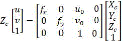


其中,


在小孔模型中,一条直线在成像平面上的向应该仍为直线,但是在实际拍摄过程中,由于拍摄设备均用到了透镜,往往将直线投影为曲线,越靠近图像的边缘越明显。透镜往往是中心对称的,以至于这种不规则的畸变通常是径向对称的,统称径向畸变。In the pinhole model, the direction of a straight line on the imaging plane should still be a straight line, but in the actual shooting process, since the shooting equipment uses lenses, the straight line is often projected as a curve, and the closer it is to the edge of the image, the more obvious it is. Lenses tend to be centrosymmetric, so that this irregular distortion is usually radially symmetric, collectively referred to as radial distortion.
本申请在标定内参时,还包括畸变消除步骤,设


其中,

径向畸变的中心位置与相机的主心位置相同,有:The center position of the radial distortion is the same as the camera's main center position, as follows:

其中,


设

即:which is:

设有n个图像,每个图像有m个点,则有2mn个径向畸变像素坐标,畸变像素坐标矩阵为:There are n images, each image has m points, then there are 2mn radial distortion pixel coordinates, and the distortion pixel coordinate matrix is:

其中,


基于所述畸变像素坐标矩阵,通过最小二乘法获得畸变系数:Based on the distorted pixel coordinate matrix, the distortion coefficients are obtained by the least squares method:

目标函数采用最小化重投影误差,将空间坐标按照估计的投影方程投影到图像上,使像素估计值与实际观测值之间的误差最小,通过最大似然估计方法优化目标函数:The objective function is to minimize the reprojection error, and the spatial coordinates are projected onto the image according to the estimated projection equation, so that the error between the pixel estimated value and the actual observed value is minimized, and the objective function is optimized by the maximum likelihood estimation method:

其中,


基于所述目标函数,通过LM算法,以畸变系数的解作为初始值进行迭代获得目标函数的最优解。Based on the objective function, through the LM algorithm, the optimal solution of the objective function is obtained iteratively with the solution of the distortion coefficient as the initial value.
通过最大似然估计和LM算法对目标函数进行迭代优化,得到最优解,能减少因噪声带来的标定误差,获取更精确的相机内外参数,提高最终求取世界坐标的精度。The objective function is iteratively optimized by maximum likelihood estimation and LM algorithm, and the optimal solution is obtained, which can reduce the calibration error caused by noise, obtain more accurate internal and external parameters of the camera, and improve the accuracy of the final calculation of the world coordinates.
获取相机的内参和外参过程,都需要尽量减小其标定误差,提高最后计算三维坐标的精度。除上述介绍的,根据相机的焦距、物体到相机的距离,选取合适的标定板规格,能相应减小标定误差,还有一些其他途径,也能从其他方面,减小标定误差。In the process of obtaining the internal and external parameters of the camera, it is necessary to minimize the calibration error and improve the accuracy of the final calculation of the three-dimensional coordinates. In addition to the above introduction, according to the focal length of the camera and the distance from the object to the camera, selecting the appropriate calibration plate specifications can reduce the calibration error accordingly, and there are other ways to reduce the calibration error from other aspects.
本发明中减小标定误差的途径主要还有:The ways to reduce the calibration error in the present invention mainly include:
(1)标定板平面保持平整。标定板是一个二维的图像,无论是手动打印还是现有的标定板,都需要将所有的棋盘格保持在同一个平面上;(1) The plane of the calibration plate should be kept flat. The calibration board is a two-dimensional image, whether it is manually printed or an existing calibration board, all checkerboards need to be kept on the same plane;
(2)内参标定拍摄图片时,相机最好要从标定板不同的视角进行拍摄,拍摄照片要覆盖标定板的每一个位置,图片数量在20张以上;(2) When taking pictures with internal parameter calibration, it is better for the camera to take pictures from different perspectives of the calibration board, and the photos should cover every position of the calibration board, and the number of pictures should be more than 20;
(3)标定内参时,剔除重投影(即通过获取到的相机内外参数,将世界坐标系的点转换为像素坐标)误差较大(即大于设定误差阈值)的标定图像。标定图像的重投影误差用来判定标定效果,重投影误差较大的标定图像,往往角点检测不太准确从而影响标定。(3) When calibrating the internal parameters, the re-projection (that is, converting the points of the world coordinate system into pixel coordinates through the acquired internal and external parameters of the camera) is excluded from the calibration images with large errors (that is, greater than the set error threshold). The re-projection error of the calibration image is used to determine the calibration effect. The calibration image with a large re-projection error is often inaccurate in corner detection, which affects the calibration.
另外,三维客观世界中的物体经由摄像机,利用光学成像原理形成影像并把其处理为计算机能够识别格式的过程称之为图像的采集。在图像采集过程中,光照起着重要作用,它可以直接影响形成图像的质量和图像的应用效率。光源从大类上可分为普通自然光和人造光源,由光照强度、色温及光源的几何形状来描述。为使采集到的图像达到高质量的要求,需要依据待检测目标的颜色、材质和形状,考虑所需光源的强度、光路和光谱等特性。In addition, the process of forming images of objects in the three-dimensional objective world by using the principle of optical imaging and processing them into a format that can be recognized by computers is called image acquisition. In the process of image acquisition, illumination plays an important role, which can directly affect the quality of the formed image and the application efficiency of the image. Light sources can be classified into ordinary natural light and artificial light sources, which are described by light intensity, color temperature and the geometry of the light source. In order to make the collected images meet the high-quality requirements, it is necessary to consider the intensity, light path and spectrum of the required light source according to the color, material and shape of the target to be detected.
视觉光源有白色、蓝色、红色、绿色、红外、紫外等颜色,每种颜色的波长各不相同,也适用于不同的场景下使用。白色光源通常光源适用性广,亮度高,更多地使用在拍摄彩色图像场景中。蓝色光源广泛用于金属材质的产品。红色光源可以透过一些比较暗的物体,常常用来提高对比度。绿色光源主要针红色、银色背景产品。红外光属于不可见光,但其有较强的透过力,一般在LCD屏检测、视频监控行业应用的比较普遍。紫外光穿透力强,主要应用于证件检测、触摸屏ITO检测、布料表面破损、点胶溢胶检测等方面,金属表面划痕检测等领域。The visual light source has white, blue, red, green, infrared, ultraviolet and other colors. The wavelength of each color is different, and it is also suitable for use in different scenarios. White light sources are usually light sources with wide applicability and high brightness, and are more often used in the scene of shooting color images. Blue light sources are widely used in metal products. Red light sources can pass through some darker objects and are often used to improve contrast. The green light source mainly needles red and silver background products. Infrared light belongs to invisible light, but it has strong transmittance, and it is generally used in LCD screen detection and video surveillance industries. Ultraviolet light has strong penetrating power and is mainly used in document detection, touch screen ITO detection, cloth surface damage, glue spill detection, etc., metal surface scratch detection and other fields.
机器视觉照明系统最常用的照明方式有前向照明和背向照明两种,如图6所示。前向照明光源置于物体前面,主要用于照射物体的表面缺陷以及细节特征。而背向照明光源置于物体后面,提高目标物与周边环境的对比度,能突显物体的轮廓及液面位置,主要用于精密测量系统中。The most commonly used lighting methods for machine vision lighting systems are forward lighting and back lighting, as shown in Figure 6. The forward illumination light source is placed in front of the object and is mainly used to illuminate the surface defects and detailed features of the object. The back-illuminated light source is placed behind the object to improve the contrast between the target and the surrounding environment, and can highlight the contour of the object and the position of the liquid level. It is mainly used in precision measurement systems.
在配液室内采集到的针头图像,往往会有很多背景元素的干扰,而针尖本身就是比较小的目标,因此优选采用红色背光源对针筒针头进行打光,消除背景杂乱物体的干扰,同时突出针头的轮廓。即在相机内外参标定好后,通过两个不同方位的相机在设定颜色种类光源以及设定光源照明方向下采集待检测的针头图像,作为输入图像。The needle image collected in the dosing room is often disturbed by many background elements, and the needle tip itself is a relatively small target. Therefore, it is preferable to use a red backlight to illuminate the needle of the syringe to eliminate the interference of background cluttered objects, and at the same time Highlight the outline of the needle. That is, after the internal and external parameters of the camera are calibrated, two cameras with different orientations are used to collect the image of the needle to be detected under the set color type light source and the set light source illumination direction as the input image.
S20,对所述输入图像进行预处理,得到预处理图像;所述预处理包括去噪、二值化以及直方图均衡化处理;S20, preprocessing the input image to obtain a preprocessing image; the preprocessing includes denoising, binarization, and histogram equalization;
摄像机中的图像传感器、图像信号的传输过程、以及采集现场种光源、背景的复杂性,都会导致采集到的图片有很多噪声点,因此在图像预处理时,我们需要先对图像去噪。而此视觉检测方案中,针尖的检测需要用到边缘检测,是非常重要的一个环节,因此为了在去噪过程中,尽量保留边缘信息。因此在本实施例中,采用了双边滤波的方法对针头图像进行去噪,能在保持边界清晰的情况下有效的去除噪音。The image sensor in the camera, the transmission process of the image signal, and the complexity of the light source and background in the collection site will all lead to a lot of noise in the collected image. Therefore, during image preprocessing, we need to denoise the image first. In this visual detection scheme, edge detection is required for the detection of the needle tip, which is a very important link. Therefore, in order to preserve the edge information as much as possible during the denoising process. Therefore, in this embodiment, the bilateral filtering method is used to denoise the needle image, which can effectively remove noise while keeping the boundary clear.
去噪后,对针头图像进行均衡化处理。在均衡化处理时,同样考虑到边界信息的保留,因此,在本实施例中,会对针头图像进行直方图均衡化。均衡化后的图像如图7(a)所示。After denoising, the needle image is equalized. During the equalization process, the preservation of boundary information is also considered. Therefore, in this embodiment, histogram equalization is performed on the needle image. The equalized image is shown in Fig. 7(a).
另外,在配液图像处理中,我们更关注的是物体的边缘信息,二值化图像已经可以满足要求,并且基于二值化图像的各种处理速度也有很大的提升。在本发明中我们采用的是OpenCV中动态阈值法,该方法在考虑像素的坐标位置关系的前提下,对不同像素自动选择不同阈值,实现动态阈值法。动态阈值二值化结果如图7(b)所示。In addition, in the processing of liquid dispensing images, we pay more attention to the edge information of objects. Binarized images can already meet the requirements, and various processing speeds based on binary images have also been greatly improved. In the present invention, we use the dynamic threshold method in OpenCV, which automatically selects different thresholds for different pixels under the premise of considering the coordinate position relationship of the pixels to realize the dynamic threshold method. The dynamic threshold binarization results are shown in Fig. 7(b).
S30,采用预设的基于角点的ROI提取方法提取所述预处理图像中的ROI区域;S30, using a preset corner-based ROI extraction method to extract the ROI region in the preprocessed image;
在本实施例中,只有针头部位才是我们需要关注的区域。ROI的提取,既在一定程度上减少了背景区域特征的干扰,又提高了检测算法的效率。从灰度图7(b)我们能看出,背光源区域内是我们所想提取的图像,即光源的四个角点组成的区域。In this embodiment, only the needle site is the area we need to pay attention to. The extraction of ROI not only reduces the interference of the background area features to a certain extent, but also improves the efficiency of the detection algorithm. From the grayscale image 7(b), we can see that the area of the backlight source is the image we want to extract, that is, the area composed of the four corners of the light source.
在本发明中,采用预设的基于角点的ROI提取方法提取所述预处理图像中的ROI区域,其原理就是图像的灰度在垂直于背光源角点两个边缘的两个方向上变化都较大,找到这样的角点,然后就可以描绘出图像的 ROI 区域,即利用OpenCV中的角点检测函数获取角点,然后求所有角点对应的最小外接矩形,则可以提取到基于角点的ROI区域,提取结果如图7(c)。此方法可以根据实际应用场景,自适应地提取ROI区域。In the present invention, a preset corner-based ROI extraction method is used to extract the ROI region in the preprocessed image. The principle is that the grayscale of the image changes in two directions perpendicular to the two edges of the corners of the backlight source. If such corner points are found, then the ROI area of the image can be drawn, that is, the corner points are obtained by using the corner detection function in OpenCV, and then the minimum circumscribed rectangle corresponding to all the corner points can be obtained. The ROI area of the point, the extraction result is shown in Figure 7(c). This method can adaptively extract the ROI area according to the actual application scenario.
S40,通过边缘检测方法获取所述ROI区域中针头的边缘轮廓,并通过角点检测确定针尖的位置,进而得到针尖的像素坐标;S40, obtain the edge contour of the needle tip in the ROI area through an edge detection method, and determine the position of the needle tip through corner point detection, and then obtain the pixel coordinates of the needle tip;
边缘检测就是简化图像信息,使用边缘线代表图像所携带的信息。而针头位置的边缘检测,是针尖位置确定的关键。Edge detection is to simplify image information and use edge lines to represent the information carried by the image. The edge detection of the needle position is the key to determine the needle position.
边缘检测本质上也是一种滤波算法,不同的算子有不同的提取效果,区别在于滤波器的选择。传统的边缘检测算子有Sobel 算子、Robert 算子、Prewitt 算子、LOG 算子、Canny算子等。Canny边缘算子是边缘检测算自重最为常用的一种,也通常被认为最优秀的边缘检测算子。它是一个多级边缘检测算法,提出了边缘检测优劣评判的三条标准:高的检测率、精确定位、明确的响应。因此我们采用OpenCV中Canny算子边缘检测,找到针头部位的边缘,如图8(a)所示。Edge detection is essentially a filtering algorithm. Different operators have different extraction effects, and the difference lies in the selection of filters. Traditional edge detection operators include Sobel operator, Robert operator, Prewitt operator, LOG operator, Canny operator, etc. The Canny edge operator is one of the most commonly used edge detection operators, and is generally considered to be the best edge detection operator. It is a multi-level edge detection algorithm, which proposes three criteria for the evaluation of edge detection: high detection rate, precise positioning, and clear response. Therefore, we use the Canny operator edge detection in OpenCV to find the edge of the needle, as shown in Figure 8(a).
对于针头部位,只需要关注细长的针的部位,并且轮廓基本上是竖直的线条,因此根据竖直线的检测,参考图8(b),大致确定细长针的范围,结果如图8(c),同时去除过多背景元素的干扰。最后利用角点检测,确定最下方的角点即为针尖,结果如图8(d)所示。具体过程如下:For the needle part, only need to pay attention to the slender needle part, and the outline is basically a vertical line, so according to the detection of the vertical line, referring to Figure 8(b), roughly determine the range of the slender needle, and the result is shown in the figure 8(c), while removing the distraction of too many background elements. Finally, using corner detection, it is determined that the bottom corner is the needle tip, and the result is shown in Figure 8(d). The specific process is as follows:
通过边缘检测方法获取所述ROI区域中针头的边缘轮廓;Obtain the edge contour of the needle in the ROI area by an edge detection method;
提取边缘轮廓中的竖直线,并计算水平方向竖直线之间的最大距离;Extract the vertical lines in the edge contour, and calculate the maximum distance between the vertical lines in the horizontal direction;
判断所述最大距离是否大于设定的距离阈值,若大于,则将该水平方向以上的ROI区域删除;Determine whether the maximum distance is greater than the set distance threshold, and if it is greater, delete the ROI area above the horizontal direction;
提取未删除的ROI区域中的竖直线并进行角点检测,将未删除的ROI区域中最长竖直线的最下方的角点作为针尖的位置。Extract the vertical line in the undeleted ROI area and perform corner detection, and use the bottom corner of the longest vertical line in the undeleted ROI area as the position of the needle tip.
S50,结合两个不同方位的针尖的像素坐标,通过预设第一位姿求解方法得到针尖对应的世界三维坐标;所述第一位姿求解方法为根据两幅图像的位姿结果求解像素点的世界坐标的方法;S50, combining the pixel coordinates of the needle tips in two different orientations, obtain the three-dimensional world coordinates corresponding to the needle tip through a preset first pose solution method; the first pose solution method is to solve the pixel points according to the pose results of the two images method of world coordinates;
根据两幅图像的位姿结果求解像素点的世界坐标的方法具体如下:The method of solving the world coordinates of the pixel points according to the pose results of the two images is as follows:
根据两条直线确定一个点的原理,在二维平面中只要知道两条相交直线的方程,
就可以解出它们的交点坐标。现在假设我们是在二维平面中拍照的,如图9(a),其中


到三维空间中,原理跟二维是一样的,只是两条直线从二维空间升到了三维空间。
同样通过解PNP求出了相机两次拍摄的空间位置


待求点


此时我们得到了


为了抵消旋转对


两个方向的相机都进行相机坐标系和世界坐标系的转换,分别得到两条直线A、B,
求出两条直线的交点坐标,即为点P。通常由于误差的存在,A与B相交的可能性几乎不存在,
因此在计算时,求两条之间的最近点坐标的中点

在本实施例中,结合两个不同方位的针尖的像素坐标,通过根据两幅图像的位姿结果求解像素点的世界坐标的方法得到针尖对应的世界三维坐标。In this embodiment, combining the pixel coordinates of the needle tips in two different orientations, the world three-dimensional coordinates corresponding to the needle tip are obtained by solving the world coordinates of the pixel points according to the pose results of the two images.
S60,计算步骤S50获取的世界三维坐标与机器人在开始配液前的计算的标准世界三维坐标的误差,并根据该误差纠正步骤S50获取的世界三维坐标,进而机器人基于纠正后的世界三维坐标进行配液。S60, calculating the error between the world three-dimensional coordinates obtained in step S50 and the standard world three-dimensional coordinates calculated by the robot before starting the liquid dispensing, and correcting the world three-dimensional coordinates obtained in step S50 according to the error, and then the robot performs the correction based on the corrected world three-dimensional coordinates. Dosing.
在本实施例中,机器人在开始配液前,则基于步骤S10-步骤S50,计算针尖的世界
三维坐标,作为标准世界三维坐标。机器人开始配液后,计算当前次的世界三维坐标(

本发明第二实施例的一种用于机器人自动配液的针尖位置检测系统,如图2所示,具体包括以:图像获取模块100、预处理模块200、ROI区域提取模块300、检测模块400、世界三维坐标求解模块500、配液模块600;As shown in FIG. 2 , a needle tip position detection system for automatic liquid dispensing by a robot according to the second embodiment of the present invention specifically includes: an
所述图像获取模块100,配置为通过两个不同方位的相机在设定颜色种类光源以及设定光源照明方向下采集待检测的针头图像,作为输入图像;The
所述预处理模块200,配置为对所述输入图像进行预处理,得到预处理图像;所述预处理包括去噪、二值化以及直方图均衡化处理;The
所述ROI区域提取模块300,配置为采用预设的基于角点的ROI提取方法提取所述预处理图像中的ROI区域;The ROI
所述检测模块400,配置为通过边缘检测方法获取所述ROI区域中针头的边缘轮廓,并通过角点检测确定针尖的位置,进而得到针尖的像素坐标;The
所述世界三维坐标求解模块500,配置为结合两个不同方位的针尖的像素坐标,通过预设第一位姿求解方法得到针尖对应的世界三维坐标;所述第一位姿求解方法为根据两幅图像的位姿结果求解像素点的世界坐标的方法;The world three-dimensional coordinate solving
所述配液模块600,配置为计算世界三维坐标求解模块获取的世界三维坐标与机器人在开始配液前的计算的标准世界三维坐标的误差,并根据该误差纠正世界三维坐标求解模块获取的世界三维坐标,进而机器人基于纠正后的世界三维坐标进行配液。The
所述技术领域的技术人员可以清楚的了解到,为描述的方便和简洁,上述描述的系统具体的工作过程及有关说明,可以参考前述方法实施例中的对应过程,在此不再赘述。Those skilled in the technical field can clearly understand that, for the convenience and brevity of description, for the specific working process and related description of the system described above, reference may be made to the corresponding process in the foregoing method embodiments, which will not be repeated here.
需要说明的是,上述实施例提供的用于机器人自动配液的针尖位置检测系统,仅以上述各功能模块的划分进行举例说明,在实际应用中,可以根据需要而将上述功能分配由不同的功能模块来完成,即将本发明实施例中的模块或者步骤再分解或者组合,例如,上述实施例的模块可以合并为一个模块,也可以进一步拆分成多个子模块,以完成以上描述的全部或者部分功能。对于本发明实施例中涉及的模块、步骤的名称,仅仅是为了区分各个模块或者步骤,不视为对本发明的不当限定。It should be noted that the needle tip position detection system for automatic liquid dispensing by the robot provided in the above embodiment is only illustrated by the division of the above functional modules. In practical applications, the above functions can be allocated by different The modules or steps in the embodiments of the present invention are further decomposed or combined. For example, the modules in the above-mentioned embodiments can be combined into one module, or can be further split into multiple sub-modules to complete all the above-described or some functions. The names of the modules and steps involved in the embodiments of the present invention are only for distinguishing each module or step, and should not be regarded as an improper limitation of the present invention.
本发明第三实施例的一种电子设备,至少一个处理器;以及与至少一个所述处理器通信连接的存储器;其中,所述存储器存储有可被所述处理器执行的指令,所述指令用于被所述处理器执行以实现权利要求上述的用于机器人自动配液的针尖位置检测方法。An electronic device according to a third embodiment of the present invention, at least one processor; and a memory communicatively connected to at least one of the processors; wherein the memory stores instructions executable by the processor, the instructions The method is used for being executed by the processor to realize the method for detecting the position of the needle tip for automatic liquid dispensing by the robot as claimed above.
本发明第四实施例的一种计算机可读存储介质,所述计算机可读存储介质存储有计算机指令,所述计算机指令用于被所述计算机执行以实现权利要求上述的用于机器人自动配液的针尖位置检测方法。A computer-readable storage medium according to a fourth embodiment of the present invention stores computer instructions, and the computer instructions are used to be executed by the computer to realize the automatic liquid dispensing for robots described in the claims. The needle tip position detection method.
所述技术领域的技术人员可以清楚的了解到,未描述的方便和简洁,上述描述的设备、计算机可读存储介质的具体工作过程及有关说明,可以参考前述方法实例中的对应过程,在此不再赘述。Those skilled in the technical field can clearly understand that the undescribed convenience and brevity, the specific working process and related description of the above-described device and computer-readable storage medium, can refer to the corresponding process in the foregoing method example, here. No longer.
下面参考图10,其示出了适于用来实现本申请系统、方法、设备实施例的服务器的计算机系统的结构示意图。图10示出的服务器仅仅是一个示例,不应对本申请实施例的功能和使用范围带来任何限制。Referring to FIG. 10 below, it shows a schematic structural diagram of a computer system suitable for implementing the server of the system, method, and device embodiments of the present application. The server shown in FIG. 10 is only an example, and should not impose any limitations on the functions and scope of use of the embodiments of the present application.
如图10所示,计算机系统包括中央处理单元(CPU,Central Processing Unit)1001,其可以根据存储在只读存储器(ROM,Read Only Memory)1002中的程序或者从存储部分1008加载到随机访问存储器(RAM,Random Access Memory)1003中的程序而执行各种适当的动作和处理。在RAM1003中,还存储有系统操作所需的各种程序和数据。CPU1001、ROM1002以及RAM1003通过总线1004彼此相连。输入/输出(I/O,Input/Output)接口1005也连接至总线1004。As shown in FIG. 10 , the computer system includes a central processing unit (CPU, Central Processing Unit) 1001, which can be loaded into a random access memory according to a program stored in a read only memory (ROM, Read Only Memory) 1002 or from a storage part 1008 (RAM, Random Access Memory) 1003 executes various appropriate operations and processes. In the
以下部件连接至I/O接口1005:包括键盘、鼠标等的输入部分1006;包括诸如阴极射线管、液晶显示器等以及扬声器等的输出部分1007;包括硬盘等的存储部分1008;以及包括诸如局域网卡、调制解调器等的网络接口卡的通讯部分1009。通讯部分1009经由诸如因特网的网络执行通讯处理。驱动器1010也根据需要连接至I/O接口1005。可拆卸介质1011,诸如磁盘、光盘、磁光盘、半导体存储器等等,根据需要安装在驱动器1010上,以便于从其上读出的计算机程序根据需要被安装入存储部分1008。The following components are connected to the I/O interface 1005: an
特别地,根据本公开的实施例,上文参考流程图描述的过程可以被实现为计算机软件程序。例如,本公开的实施例包括一种计算机程序产品,其包括承载在计算机可读介质上的计算机程序,该计算机程序包含用于执行流程图所示的方法的程序代码。在这样的实施例中,该计算机程序可以通过通讯部分1009从网络上被下载和安装,和/或从可拆卸介质1011被安装。在该计算机程序被CPU1001执行时,执行本申请的方法中限定的上述功能。需要说明的是,本申请上述的计算机可读介质可以是计算机可读信号介质或者计算机可读存储介质或者是上述两者的任意组合。计算机可读存储介质例如可以是但不限于:电、磁、光、电磁、红外线、或半导体的系统、装置或器件,或者任意以上的组合。计算机可读存储介质的更具体的例子可以包括但不限于:具有一个或多个导线的电连接、便携式计算机磁盘、硬盘、RAM、ROM、可擦式可编程只读存储器(EPROM或闪存)、光纤、便携式紧凑磁盘只读存储器(CD-ROM)、光存储器件、磁存储器件、或者上述的任意合适的组合。在本申请中,计算机可读存储介质可以是任何包含或存储程序的有形介质,该程序可以被指令执行系统、装置或者器件使用或者与其结合使用。而在本申请中,计算机可读的信号介质可以包括在基带中或者作为载波一部分传播的数据信号,其中承载了计算机可读的程序代码。这种传播的数据信号可以采用多种形式,包括但不限于电磁信号、光信号或上述的任意合适的组合。计算机可读的信号介质还可以是计算机可读存储介质以外的任何计算机可读介质,该计算机可读介质可以发送、传播或者传输用于由指令执行系统、装置或者器件使用或者与其结合使用的程序。计算机可读介质上包含的程序代码可以用任何适当的介质传输,包括但不限于:无线、电线、光缆等等,或者上述的任意合适的组合。In particular, according to embodiments of the present disclosure, the processes described above with reference to the flowcharts may be implemented as computer software programs. For example, embodiments of the present disclosure include a computer program product comprising a computer program carried on a computer-readable medium, the computer program containing program code for performing the method illustrated in the flowchart. In such an embodiment, the computer program may be downloaded and installed from the network via the
可以以一种或多种程序设计语言或其组合来编写用于执行本申请的操作的计算机程序代码,上述程序设计语言包括面向对象的程序设计语言,如Java、Smalltalk、C++,还包括常规的过程式程序设计语言,如C语言或类似的程序设计语言。程序代码可以完全地在用户计算机上执行、部分地在用户计算机上执行、作为一个独立的软件包执行、部分在用户计算机上部分在远程计算机上执行、或者完全在远程计算机或服务器上执行。在涉及远程计算机的情形中,远程计算机可以通过任意种类的网络,包括局域网或广域网连接到用户计算机,或者可以连接到外部计算机(例如利用因特网服务提供商来通过因特网连接)。Computer program code for performing the operations of the present application may be written in one or more programming languages, including object-oriented programming languages such as Java, Smalltalk, C++, and conventional A procedural programming language, such as C or a similar programming language. The program code may execute entirely on the user's computer, partly on the user's computer, as a stand-alone software package, partly on the user's computer and partly on a remote computer, or entirely on the remote computer or server. Where a remote computer is involved, the remote computer may be connected to the user computer through any kind of network, including a local or wide area network, or may be connected to an external computer (eg, using an Internet service provider to connect through the Internet).
附图中的流程图和框图,图示了按照本申请各种实施例的系统、方法和计算机程序产品的可能实现的体系架构、功能和操作。在这点上,流程图或框图中的每个方框可以代表一个模块、程序段、或代码的一部分,该模块、程序段、或代码的一部分包含一个或多个用于实现规定的逻辑功能的可执行指令。也应当注意,在有些作为替换的实现中,方框中所标注的功能也可以以不同于附图中所标注的顺序发生。例如,两个接连表示的方框实际上可以基本并行地执行,它们有时也可以按相反的顺序执行,这依所涉及的功能而定。也要注意的是,框图和/或流程图中的每个方框、以及框图和/或流程图中的方框的组合,可以用执行规定的功能或操作的专用的基于硬件的系统来实现,或者可以用专用硬件与计算机指令的组合来实现。The flowchart and block diagrams in the Figures illustrate the architecture, functionality, and operation of possible implementations of systems, methods and computer program products according to various embodiments of the present application. In this regard, each block in the flowchart or block diagrams may represent a module, segment, or portion of code that contains one or more logical functions for implementing the specified functions executable instructions. It should also be noted that, in some alternative implementations, the functions noted in the blocks may occur out of the order noted in the figures. For example, two blocks shown in succession may, in fact, be executed substantially concurrently, or the blocks may sometimes be executed in the reverse order, depending upon the functionality involved. It is also noted that each block of the block diagrams and/or flowchart illustrations, and combinations of blocks in the block diagrams and/or flowchart illustrations, can be implemented in dedicated hardware-based systems that perform the specified functions or operations , or can be implemented in a combination of dedicated hardware and computer instructions.
术语“第一”、“第二”等是用于区别类似的对象,而不是用于描述或表示特定的顺序或先后次序。The terms "first," "second," etc. are used to distinguish between similar objects, and are not used to describe or indicate a particular order or sequence.
术语“包括”或者任何其它类似用语旨在涵盖非排他性的包含,从而使得包括一系列要素的过程、方法、物品或者设备/装置不仅包括那些要素,而且还包括没有明确列出的其它要素,或者还包括这些过程、方法、物品或者设备/装置所固有的要素。The term "comprising" or any other similar term is intended to encompass a non-exclusive inclusion such that a process, method, article or device/means comprising a list of elements includes not only those elements but also other elements not expressly listed, or Also included are elements inherent to these processes, methods, articles or devices/devices.
至此,已经结合附图所示的优选实施方式描述了本发明的技术方案,但是,本领域技术人员容易理解的是,本发明的保护范围显然不局限于这些具体实施方式。在不偏离本发明的原理的前提下,本领域技术人员可以对相关技术特征作出等同的更改或替换,这些更改或替换之后的技术方案都将落入本发明的保护范围之内。So far, the technical solutions of the present invention have been described with reference to the preferred embodiments shown in the accompanying drawings, however, those skilled in the art can easily understand that the protection scope of the present invention is obviously not limited to these specific embodiments. Without departing from the principle of the present invention, those skilled in the art can make equivalent changes or substitutions to the relevant technical features, and the technical solutions after these changes or substitutions will fall within the protection scope of the present invention.
Claims (10)



Priority Applications (1)
| Application Number | Priority Date | Filing Date | Title |
|---|---|---|---|
| CN202110803839.9A CN113487510A (en) | 2021-07-16 | 2021-07-16 | Method, system and equipment for detecting needle point position for automatic liquid preparation of robot |
Applications Claiming Priority (1)
| Application Number | Priority Date | Filing Date | Title |
|---|---|---|---|
| CN202110803839.9A CN113487510A (en) | 2021-07-16 | 2021-07-16 | Method, system and equipment for detecting needle point position for automatic liquid preparation of robot |
Publications (1)
| Publication Number | Publication Date |
|---|---|
| CN113487510A true CN113487510A (en) | 2021-10-08 |
Family
ID=77938961
Family Applications (1)
| Application Number | Title | Priority Date | Filing Date |
|---|---|---|---|
| CN202110803839.9A Pending CN113487510A (en) | 2021-07-16 | 2021-07-16 | Method, system and equipment for detecting needle point position for automatic liquid preparation of robot |
Country Status (1)
| Country | Link |
|---|---|
| CN (1) | CN113487510A (en) |
Cited By (9)
| Publication number | Priority date | Publication date | Assignee | Title |
|---|---|---|---|---|
| CN114429465A (en) * | 2022-01-26 | 2022-05-03 | 北京柏惠维康科技有限公司 | Method, device and equipment for calibrating needle point position of surgical navigation probe and readable medium |
| CN115115813A (en) * | 2022-03-03 | 2022-09-27 | 中国人民解放军总医院第四医学中心 | Intelligent construction method for standard body position of human skeleton |
| CN115690067A (en) * | 2022-11-10 | 2023-02-03 | 四川制药制剂有限公司 | A kind of detection method and detection device of amoxicillin sodium aluminum cap crimping for injection |
| CN116071358A (en) * | 2023-03-07 | 2023-05-05 | 江西省智能产业技术创新研究院 | Automobile chassis detection method and readable storage medium |
| CN116934692A (en) * | 2023-07-06 | 2023-10-24 | 深圳市维谱科技有限公司 | Head offset determination method for automation device, and storage medium |
| CN117274264A (en) * | 2023-11-22 | 2023-12-22 | 苏州易来科得科技有限公司 | Intelligent assembling method and device for mechanical parts of secondary battery |
| CN117372513A (en) * | 2022-06-30 | 2024-01-09 | 北京极智嘉科技股份有限公司 | Container positioning method, device, container access equipment and storage medium |
| CN117516485A (en) * | 2024-01-04 | 2024-02-06 | 东北大学 | A position and attitude visual measurement method for automatic guidance and installation of aircraft engines |
| CN119887702A (en) * | 2024-12-30 | 2025-04-25 | 四川深瑞视科技有限公司 | Method, device, equipment and medium for detecting inclination of tray lens |
Citations (5)
| Publication number | Priority date | Publication date | Assignee | Title |
|---|---|---|---|---|
| CN109069855A (en) * | 2016-04-19 | 2018-12-21 | Oh & Lee医疗机器人公司 | Utilize the laser irradiation device and method of mechanical arm |
| CN110619660A (en) * | 2019-08-21 | 2019-12-27 | 深圳市优必选科技股份有限公司 | Object positioning method and device, computer readable storage medium and robot |
| CN111243032A (en) * | 2020-01-10 | 2020-06-05 | 大连理工大学 | Full-automatic checkerboard angular point detection method |
| CN112258455A (en) * | 2020-09-28 | 2021-01-22 | 上海工程技术大学 | Detection method for detecting spatial position of part based on monocular vision |
| CN113001564A (en) * | 2021-03-11 | 2021-06-22 | 中国科学院自动化研究所 | Automatic liquid distribution system and method based on industrial robot |
-
2021
- 2021-07-16 CN CN202110803839.9A patent/CN113487510A/en active Pending
Patent Citations (5)
| Publication number | Priority date | Publication date | Assignee | Title |
|---|---|---|---|---|
| CN109069855A (en) * | 2016-04-19 | 2018-12-21 | Oh & Lee医疗机器人公司 | Utilize the laser irradiation device and method of mechanical arm |
| CN110619660A (en) * | 2019-08-21 | 2019-12-27 | 深圳市优必选科技股份有限公司 | Object positioning method and device, computer readable storage medium and robot |
| CN111243032A (en) * | 2020-01-10 | 2020-06-05 | 大连理工大学 | Full-automatic checkerboard angular point detection method |
| CN112258455A (en) * | 2020-09-28 | 2021-01-22 | 上海工程技术大学 | Detection method for detecting spatial position of part based on monocular vision |
| CN113001564A (en) * | 2021-03-11 | 2021-06-22 | 中国科学院自动化研究所 | Automatic liquid distribution system and method based on industrial robot |
Non-Patent Citations (5)
| Title |
|---|
| 刘晶晶: ""基于双目立体视觉的三维定位技术研究"", 《中国知网文献知网节》 * |
| 李超 等: ""基于Matlab的相机内参和畸变参数优化方法"", 《电子科技》 * |
| 英红: "《基于视觉的水泥路面病害检测方法》", 31 October 2014, 成都:电子科技大学出版社 * |
| 陈素霞: ""图像感兴趣区域提取技术研究"", 《中国优秀博硕士学位论文全文数据库(硕士) 信息科技辑》 * |
| 雷海兵: ""双目立体视觉在全针测量系统中的应用研究"", 《中国优秀博硕士学位论文全文数据库(硕士) 信息科技辑》 * |
Cited By (12)
| Publication number | Priority date | Publication date | Assignee | Title |
|---|---|---|---|---|
| CN114429465A (en) * | 2022-01-26 | 2022-05-03 | 北京柏惠维康科技有限公司 | Method, device and equipment for calibrating needle point position of surgical navigation probe and readable medium |
| CN115115813A (en) * | 2022-03-03 | 2022-09-27 | 中国人民解放军总医院第四医学中心 | Intelligent construction method for standard body position of human skeleton |
| CN115115813B (en) * | 2022-03-03 | 2023-08-22 | 中国人民解放军总医院第四医学中心 | Intelligent Construction Method of Standard Body Position of Human Skeleton |
| CN117372513A (en) * | 2022-06-30 | 2024-01-09 | 北京极智嘉科技股份有限公司 | Container positioning method, device, container access equipment and storage medium |
| CN115690067A (en) * | 2022-11-10 | 2023-02-03 | 四川制药制剂有限公司 | A kind of detection method and detection device of amoxicillin sodium aluminum cap crimping for injection |
| CN116071358A (en) * | 2023-03-07 | 2023-05-05 | 江西省智能产业技术创新研究院 | Automobile chassis detection method and readable storage medium |
| CN116934692A (en) * | 2023-07-06 | 2023-10-24 | 深圳市维谱科技有限公司 | Head offset determination method for automation device, and storage medium |
| CN117274264A (en) * | 2023-11-22 | 2023-12-22 | 苏州易来科得科技有限公司 | Intelligent assembling method and device for mechanical parts of secondary battery |
| CN117274264B (en) * | 2023-11-22 | 2024-03-26 | 苏州易来科得科技有限公司 | Intelligent assembling method and device for mechanical parts of secondary battery |
| CN117516485A (en) * | 2024-01-04 | 2024-02-06 | 东北大学 | A position and attitude visual measurement method for automatic guidance and installation of aircraft engines |
| CN117516485B (en) * | 2024-01-04 | 2024-03-22 | 东北大学 | Pose vision measurement method for automatic guiding and mounting of aircraft engine |
| CN119887702A (en) * | 2024-12-30 | 2025-04-25 | 四川深瑞视科技有限公司 | Method, device, equipment and medium for detecting inclination of tray lens |
Similar Documents
| Publication | Publication Date | Title |
|---|---|---|
| CN113487510A (en) | Method, system and equipment for detecting needle point position for automatic liquid preparation of robot | |
| CN110427917B (en) | Method and device for detecting key points | |
| CN107155341B (en) | Three-dimensional scanning system and frame | |
| US9544577B2 (en) | Method of capturing three-dimensional (3D) information on a structure | |
| US7733404B2 (en) | Fast imaging system calibration | |
| CN102129680B (en) | Real-time geometry-aware projection and fast recalibration | |
| US9129435B2 (en) | Method for creating 3-D models by stitching multiple partial 3-D models | |
| WO2021115071A1 (en) | Three-dimensional reconstruction method and apparatus for monocular endoscope image, and terminal device | |
| US11430191B2 (en) | Systems and methods of augmented reality guided image capture | |
| US20170059305A1 (en) | Active illumination for enhanced depth map generation | |
| CN114697623B (en) | Projection surface selection and projection image correction method, device, projector and medium | |
| CN113516702B (en) | Automatic liquid dispensing ampoule liquid level detection method, system and liquid proportion detection method | |
| US10552984B2 (en) | Capture device calibration methods and systems | |
| CN106683068A (en) | Three-dimensional digital image acquisition method and equipment thereof | |
| CN101751672A (en) | Image processing system | |
| CN107358577B (en) | Rapid splicing method of cubic panoramic image | |
| CN111160261A (en) | Sample image labeling method and device for automatic sales counter and storage medium | |
| WO2020024684A1 (en) | Method and device for modeling three-dimensional scene, electronic device, readable storage medium, and computer apparatus | |
| CN112433641B (en) | Implementation method for automatic calibration of desktop prop interaction system of multiple RGBD depth sensors | |
| CN109191516A (en) | The rotation AA method, apparatus and readable storage medium storing program for executing of structure optical mode group | |
| CN120318306A (en) | A large panel size measurement method and system with multi-camera joint automatic calibration | |
| CN111510713B (en) | A board testing method, device, terminal and system | |
| Chierchia et al. | SALVE: A 3D Reconstruction Benchmark of Wounds from Consumer-Grade Videos | |
| JP2015052972A (en) | Measuring computer program, measuring device, and measuring method | |
| CN116258846A (en) | Image correction method, device, computer equipment and storage medium |
Legal Events
| Date | Code | Title | Description |
|---|---|---|---|
| PB01 | Publication | ||
| PB01 | Publication | ||
| SE01 | Entry into force of request for substantive examination | ||
| SE01 | Entry into force of request for substantive examination | ||
| TA01 | Transfer of patent application right |
Effective date of registration: 20221228 Address after: No. 95, Zhongguancun East Road, Haidian District, Beijing 100086 Applicant after: INSTITUTE OF AUTOMATION, CHINESE ACADEMY OF SCIENCES Applicant after: Zhongke smart medical technology development (Nanjing) Co.,Ltd. Address before: 100190 No. 95 East Zhongguancun Road, Beijing, Haidian District Applicant before: INSTITUTE OF AUTOMATION, CHINESE ACADEMY OF SCIENCES Applicant before: TIANJIN INTELLIGENT TECH. INSTITUTE OF CASIA Co.,Ltd. Applicant before: Zhongke smart medical technology development (Nanjing) Co.,Ltd. |
|
| TA01 | Transfer of patent application right | ||
| RJ01 | Rejection of invention patent application after publication |
Application publication date: 20211008 |
|
| RJ01 | Rejection of invention patent application after publication |