Multidirectional fixing device for plate processing and implementation method thereof
Technical Field
The invention relates to the technical field of metal plate processing, in particular to a multidirectional fixing device for plate processing and an implementation method thereof.
Background
The plate is a flat rectangular building material plate with standard size, which is applied to the building industry, is used as a component of a wall, a ceiling or a floor, and is also a metal plate which is forged, rolled or cast.
When sheet metal processing operation, if it is unidirectional fixed only, make sheet metal produce the skew in the in-process of processing easily and influence the machining precision, when sheet metal multi-direction is fixed, operating personnel need make a round trip to operate the fixed establishment who adjusts each position, also comparatively troublesome during the use, influences holistic work efficiency.
Therefore, a multidirectional fixing device for plate processing and an implementation method thereof are provided.
Disclosure of Invention
The invention aims to provide a multidirectional fixing device for processing a plate and an implementation method thereof, when the plate is placed at the upper end of a bottom plate, an operator can rotate a locking screw rod through a handle to drive a fixing plate to move towards one side far away from a vertical plate, when the fixing plate moves, the plate is pushed to extrude towards an elastic abutting piece, so that two sides of the plate can be limited, when the fixing plate moves, the connecting plate drives a poking plate to move to drive a turnplate to rotate, when the turnplate rotates, a push plate at the upper end is driven to rotate and press downwards, when the push plate presses downwards, the push plate presses tightly against the upper end of an inclined plane lug, when the push plate presses downwards, the inclined plane lug drives a right-angle toothed plate to move synchronously, when the right-angle toothed plate moves, the convex teeth at the bottom end are driven to synchronously move to be meshed with a rotating gear to drive the rotating gear to rotate, when the rotating gear rotates, the cam on one side is driven to synchronously rotate, the protruding end of the cam is tightly abutted to the upper end of the semicircular top cover, the semicircular top cover drives the connecting rod to descend with the pressing plate, and the pressing plate can be extruded to press and fix the upper end of the plate, so that the problems in the background are solved.
In order to achieve the purpose, the invention provides the following technical scheme: a multidirectional fixing device for plate processing comprises a supporting mechanism and a fixing mechanism, wherein the fixing mechanism is installed at the upper end of the supporting mechanism, the supporting mechanism comprises a bottom plate, a vertical plate, a locking nut, a limiting groove, an elastic abutting piece and an L-shaped side plate, the vertical plate is installed on one side of the bottom plate, the locking nut is installed at the upper end of one side, away from the bottom plate, of the vertical plate, the limiting groove is formed in the middle of the upper end of the bottom plate, the elastic abutting piece is installed at the upper end of one side, away from the vertical plate, of the bottom plate, and the L-shaped side plate is installed at one side, away from the vertical plate, of the elastic abutting piece;
the fixing mechanism comprises a locking screw, a transmission assembly, an inclined plane lug, a translation assembly, a rotating assembly and a pressing assembly, the locking screw penetrates through the middle of the locking nut and the vertical plate, the transmission assembly is installed on one side of the upper end of the locking screw, the inclined plane lug is installed on one side, away from the locking nut, of the vertical plate, the translation assembly is installed on one side of the upper end of the inclined plane lug and located at the upper end of the transmission assembly, the rotating assembly is installed at the lower end, away from the inclined plane lug, of the translation assembly and located at the upper end of the L-shaped side plate, the pressing assembly is installed at the lower end of the rotating assembly, and the pressing assembly penetrates through the upper end of the L-shaped side plate;
the L type curb plate includes backup pad, guide way, through-hole and permanent magnet A, and the backup pad is installed to the top both sides of L type curb plate, and drive assembly installs in the centre of backup pad with rotating assembly, and the guide way has been seted up to one side outer wall of backup pad, has seted up the through-hole in the middle of the top of L type curb plate, and permanent magnet A is installed to the top both sides of L type curb plate, and permanent magnet A is located the both sides of through-hole.
Further, locking screw includes handle, fixed plate, connecting plate and stopper, and locking screw keeps away from one side of bottom plate and installs the handle, and locking screw keeps away from one side of handle and installs the fixed plate, installs the connecting plate in the middle of the top of fixed plate, and the stopper is installed to one side that the connecting plate was kept away from to the fixed plate, and stopper and spacing groove swing joint.
Further, the transmission assembly comprises an installation plate, a bearing seat, a transmission shaft and a rotary table, the installation plate is welded at the bottom end of one side, away from the L-shaped side plate, of the support plate, the bearing seat is installed on the surface of the installation plate, the transmission shaft is installed in the middle of the bearing seat and penetrates through the rotary table, and the rotary table is located between the transmission shaft and the bearing seat.
Furthermore, the carousel includes push pedal, balancing weight and stirring board, and the push pedal is installed to the upper end of carousel, and the balancing weight is installed to the carousel one end of keeping away from the push pedal, and the welding of one side outer wall of carousel has the stirring board, and the carousel passes through stirring board and connecting plate swing joint.
Further, the inclined plane lug includes elastic component, locating piece and locating lever, and the elastic component is installed to one side of inclined plane lug, and the inclined plane lug passes through elastic component and riser fixed connection, and the locating piece is installed to the bottom of inclined plane lug, and the locating lever runs through the locating piece, and one side of locating lever and the outer wall welding of riser.
Further, the translation subassembly includes right-angled toothed plate, dogtooth, support and direction slide, and right-angled toothed plate is installed to upper end one side of inclined plane lug, and the dogtooth is installed to one side bottom that inclined plane lug was kept away from to right-angled toothed plate, and the support is installed to the both sides of right-angled toothed plate, and the direction slide is installed to lower extreme one side of support, and the support passes through direction slide and guide way sliding connection.
Further, the rotating assembly comprises a rotating shaft seat, a connecting shaft, a rotating gear and a cam, the rotating shaft seat is installed on one side, away from the mounting plate, of the supporting plate, the connecting shaft is installed in the middle of the rotating shaft seat, the connecting shaft penetrates through the middle of the rotating gear, the rotating gear is located at the lower end of the right-angle toothed plate and meshed with the convex teeth, and the cam is installed on one side, away from the rotating shaft seat, of the rotating gear.
Further, the pressing assembly comprises a connecting rod, a pressing plate, abutting columns and a rubber pad, the connecting rod penetrates through the through hole, the pressing plate is installed at the bottom end of the connecting rod, the abutting columns are installed on two sides of the upper end of the pressing plate, the rubber pad is installed at one end, far away from the pressing plate, of the abutting columns, and the abutting columns are movably connected with the bottom end of the L-shaped side plate through the rubber pad.
Further, the connecting rod includes half dome lid, symmetry sideboard and permanent magnet B, and half dome lid is installed to the one end that the clamp plate was kept away from to the connecting rod, and half dome lid and cam swing joint, and the symmetry sideboard is installed to the both sides of connecting rod, and the symmetry sideboard is located the upper end of L type curb plate, and permanent magnet B is installed to the bottom of symmetry sideboard, and permanent magnet B aligns with permanent magnet A.
The invention provides another technical scheme that: an implementation method of a multidirectional fixing device for plate processing comprises the following steps:
s1: when the plate is placed at the upper end of the bottom plate, an operator can rotate the locking screw rod through the handle, so that the locking screw rod drives the fixing plate to move towards one side away from the vertical plate, and when the fixing plate moves, the plate is pushed to be extruded towards the elastic abutting part;
s2: when the fixed plate moves, the connecting plate drives the shifting plate to move, so that the shifting plate drives the turntable to rotate, and when the turntable rotates, the push plate at the upper end is driven to rotate and press downwards;
s3: when the push plate is pressed downwards, the push plate is tightly abutted to the upper end of the inclined plane lug, so that the inclined plane lug drives the right-angle toothed plate to synchronously move, and when the right-angle toothed plate moves, the convex teeth at the bottom end are driven to synchronously move to be meshed with the rotating gear to drive the rotating gear to rotate;
s4: when the rotating gear rotates, the cam on one side is driven to synchronously rotate, and the protruding end of the cam is tightly abutted against the upper end of the semicircular top cover, so that the semicircular top cover drives the connecting rod to descend with the pressing plate, and the pressing plate can be extruded to be pressed and fixed at the upper end of the plate;
s5: when the plate is machined, only the locking screw is required to be rotated to restore the plate to the initial position, the two sides of the plate are not limited by pressure, and the pressing plate moves upwards to be separated from the upper end of the plate when the locking screw moves.
Compared with the prior art, the invention has the following beneficial effects:
1. the invention provides a multidirectional fixing device for processing a plate and an implementation method thereof, when the plate is placed at the upper end of a bottom plate, an operator can rotate a locking screw rod through a handle, so that the locking screw rod drives a fixing plate to move towards one side far away from a vertical plate, the fixing plate slides at the inner side of a limiting groove through a limiting block at the bottom end, when the fixing plate moves, the plate is pushed to extrude towards an elastic abutting part, so that the two sides of the plate can be limited, simultaneously, when the fixing plate moves, a connecting plate at the upper end drives a stirring plate to move, when the stirring plate is pushed by the connecting plate, a turntable is driven to rotate, so that the turntable drives a push plate at the upper end to rotate to press downwards, when the push plate presses downwards, the push plate abuts against the upper end of an inclined plane lug, so that the inclined plane lug is abutted against the push plate to move towards the vertical plate to extrude the elastic part, when the inclined plane lug moves, a positioning block at the bottom end of the inclined plane lug penetrates through a positioning rod, the inclined plane lug is kept parallel when moving, and the inclined plane lug is prevented from shifting when moving.
2. The invention provides a multidirectional fixing device for processing a plate and an implementation method thereof, wherein a right-angle toothed plate is driven to synchronously move when an inclined plane convex block moves, brackets on two sides of the right-angle toothed plate slide in a limiting way on the inner side of a guide groove through a guide sliding plate when the right-angle toothed plate moves, a convex tooth on the bottom end is driven to synchronously move and is meshed with a rotating gear to drive the rotating gear to rotate when the right-angle toothed plate moves, the rotating gear rotates in the middle of a rotating shaft seat through a connecting shaft, a cam on one side is driven to synchronously rotate when the rotating gear rotates, when one protruding end of the cam rotates to the lower end, the protruding end of the cam abuts against the upper end of a semicircular top cover, a semicircular top movable connecting rod and a pressing plate descend, so that the pressing plate can be extruded at the upper end of the plate, the two sides of the plate are limited, and the upper end of the plate is also pressed and fixed, make operating personnel only need rotate locking screw alright with fixed to the plate multidirectional, need not to make a round trip the fixed establishment of operation regulation each position, it is simple convenient.
3. The invention provides a multidirectional fixing device for processing a plate and an implementation method thereof, wherein a permanent magnet B at the bottom end of a symmetrical side plate is aligned with a permanent magnet A, homopolarity of the permanent magnet B and homopolarity of the permanent magnet A are oppositely repelled, so that a pressure plate and a connecting rod can be jacked upwards by the permanent magnet A, after the plate is processed, only a locking screw needs to be rotated to restore the original position, two sides of the plate are not limited by pressure, meanwhile, a rotary table is not driven by a connecting plate, a balancing weight at the bottom end drives the rotary table to rotate back to the original position by means of inertia, simultaneously, a push plate also separates from the upper end of an inclined plane lug along with the rotation of the rotary table after the rotary table rotates, the upper end of the inclined plane lug is propped tightly by no pressure, and is also driven by the resilience of an elastic piece to drive a right-angle toothed plate to translate to the original position, when the right-angle toothed plate translates back, a convex tooth at the bottom end is meshed with a rotating gear to drive the rotating gear to rotate clockwise, make the running gear can drive the cam and get back to initial position, will break away from the upper end of half dome cover after the cam gets back to initial position, the upper end of half dome cover is because there is not pressure to support tightly, will be by permanent magnet A jack-up upwards, makes half dome cover move the upper end that connecting rod and clamp plate rebound break away from the plate, the tight post of support that sets up will also follow the connecting rod rebound and support tightly spacing in the bottom of L type curb plate to be convenient for the quick plate that will process the completion of operating personnel takes out.
Drawings
FIG. 1 is a schematic view of the overall structure of the present invention;
FIG. 2 is a schematic structural diagram of the supporting mechanism of the present invention;
FIG. 3 is a side view of the locking screw of the present invention;
FIG. 4 is a schematic view of the mounting plate and transmission assembly of the present invention;
FIG. 5 is a schematic view of a bevel bump structure according to the present invention;
figure 6 is a schematic view of the rectangular toothed plate structure of the present invention;
FIG. 7 is a schematic view of a rotary shaft seat according to the present invention;
FIG. 8 is a schematic view of a push-down assembly according to the present invention.
In the figure: 1. a support mechanism; 11. a base plate; 12. a vertical plate; 13. locking the nut; 14. a limiting groove; 15. an elastic abutting piece; 16. an L-shaped side plate; 161. a support plate; 162. a guide groove; 163. a through hole; 164. a permanent magnet A; 2. a fixing mechanism; 21. locking the screw rod; 211. a grip; 212. a fixing plate; 213. a connecting plate; 214. a limiting block; 22. a transmission assembly; 221. mounting a plate; 222. a bearing seat; 223. a drive shaft; 224. a turntable; 2241. pushing the plate; 2242. a balancing weight; 2243. a poking plate; 23. a bevel projection; 231. an elastic member; 232. positioning blocks; 233. positioning a rod; 24. a translation assembly; 241. a rectangular toothed plate; 242. a convex tooth; 243. a support; 244. a guide slide plate; 25. a rotating assembly; 251. a rotating shaft seat; 252. a connecting shaft; 253. a rotating gear; 254. a cam; 26. pressing the assembly; 261. a connecting rod; 2611. a half dome cover; 2612. symmetrical side plates; 2613. a permanent magnet B; 262. pressing a plate; 263. tightly abutting against the column; 264. and (7) a rubber pad.
Detailed Description
The technical solutions in the embodiments of the present invention will be clearly and completely described below with reference to the drawings in the embodiments of the present invention, and it is obvious that the described embodiments are only a part of the embodiments of the present invention, and not all of the embodiments. All other embodiments, which can be derived by a person skilled in the art from the embodiments given herein without making any creative effort, shall fall within the protection scope of the present invention.
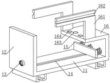
Referring to fig. 1-2, a multidirectional fixing device for processing a plate comprises a supporting mechanism 1 and a fixing mechanism 2, wherein the fixing mechanism 2 is installed at the upper end of the supporting mechanism 1, the supporting mechanism 1 comprises a bottom plate 11, a vertical plate 12, a locking nut 13, a limiting groove 14, an elastic abutting piece 15 and an L-shaped side plate 16, the vertical plate 12 is installed at one side of the bottom plate 11, the locking nut 13 is installed at the upper end of the vertical plate 12 far away from the bottom plate 11, the limiting groove 14 is formed in the middle of the upper end of the bottom plate 11, the elastic abutting piece 15 is installed at the upper end of the bottom plate 11 far away from the vertical plate 12, the L-shaped side plate 16 is installed at one side of the elastic abutting piece 15 far away from the vertical plate 12, the fixing mechanism 2 comprises a locking screw 21, a transmission assembly 22, an inclined plane lug 23, a translation assembly 24, a rotation assembly 25 and a pressing assembly 26, the locking screw 21 penetrates through the middle of the locking nut 13 and the vertical plate 12, a transmission component 22 is installed on one side of the upper end of the locking screw 21, an inclined plane convex block 23 is installed on one side of the upper end of the vertical plate 12 far away from the locking nut 13, a translation component 24 is installed on one side of the upper end of the inclined plane convex block 23, the translation component 24 is located on the upper end of the transmission component 22, a rotating component 25 is installed on the lower end of one side of the translation component 24 far away from the inclined plane convex block 23, the rotating component 25 is located on the upper end of the L-shaped side plate 16, a pressing component 26 is installed on the lower end of the rotating component 25, the pressing component 26 penetrates through the upper end of the L-shaped side plate 16, the L-shaped side plate 16 comprises a support plate 161, a guide groove 162, a through hole 163 and a permanent magnet A164, support plates 161 are installed on two sides of the top end of the L-shaped side plate 16, the transmission component 22 and the rotating component 25 are installed in the middle of the support plate 161, the guide groove 162 is opened on the outer wall of one side of the support plate 161, the through hole 163 is opened in the middle of the top end of the L-shaped side plate 16, permanent magnets a164 are mounted on both sides of the top end of the L-shaped side plate 16, and the permanent magnets a164 are located on both sides of the through hole 163.
Referring to fig. 3-5, a multidirectional fixing device for plate processing, a locking screw 21 includes a handle 211, a fixing plate 212, a connecting plate 213 and a limiting block 214, the handle 211 is installed on one side of the locking screw 21 away from a bottom plate 11, the fixing plate 212 is installed on one side of the locking screw 21 away from the handle 211, the connecting plate 213 is installed in the middle of the top end of the fixing plate 212, the limiting block 214 is installed on one side of the fixing plate 212 away from the connecting plate 213, and the limiting block 214 is movably connected with a limiting groove 14, a transmission assembly 22 includes a mounting plate 221, a bearing block 222, a transmission shaft 223 and a turntable 224, the mounting plate 221 is welded at the bottom end of one side of the support plate 161 away from the L-shaped side plate 16, the bearing block 222 is installed on the surface of the mounting plate 221, the transmission shaft 223 is installed in the middle of the bearing block 222, the transmission shaft 223 penetrates through the turntable 224, and the turntable 224 is located between the transmission shaft 223 and the bearing block 222, carousel 224 includes push pedal 2241, balancing weight 2242 and dial plate 2243, push pedal 2241 is installed to carousel 224's upper end, carousel 224 keeps away from the one end of push pedal 2241 and installs balancing weight 2242, the welding of one side outer wall of carousel 224 has dial plate 2243, and carousel 224 passes through dial plate 2243 and connecting plate 213 swing joint, inclined plane lug 23 includes elastic component 231, locating piece 232 and locating lever 233, elastic component 231 is installed to one side of inclined plane lug 23, and inclined plane lug 23 passes through elastic component 231 and riser 12 fixed connection, locating piece 232 is installed to the bottom of inclined plane lug 23, locating lever 233 runs through locating piece 232, and the outer wall welding of one side of locating lever 233 and riser 12.
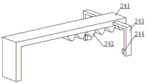
Referring to fig. 6-7, in the multi-directional fixing device for plate processing, the translation assembly 24 includes a rectangular toothed plate 241, a convex tooth 242, a bracket 243 and a guide sliding plate 244, the rectangular toothed plate 241 is installed on one side of the upper end of the inclined plane protrusion 23, the convex tooth 242 is installed on the bottom end of the rectangular toothed plate 241 far away from the inclined plane protrusion 23, the brackets 243 are installed on two sides of the rectangular toothed plate 241, the guide sliding plate 244 is installed on one side of the lower end of the bracket 243, and the bracket 243 is connected with the guide groove 162 through the guide sliding plate 244 in a sliding manner, the rotating assembly 25 includes a rotating shaft seat 251, a connecting shaft 252, a rotating gear 253 and a cam 254, the rotating shaft seat 251 is installed at one side of the support plate 161 away from the installation plate 221, the connecting shaft 252 is installed in the middle of the rotating shaft seat 251, the connecting shaft 252 penetrates through the middle of the rotating gear 253, and the rotating gear 253 is positioned at the lower end of the right-angle toothed plate 241 and is meshed with the convex teeth 242, and a cam 254 is installed at one side of the rotating gear 253, which is far away from the rotating shaft seat 251.
Referring to fig. 8, a multi-directional fixing device for processing a plate, a pressing assembly 26 includes a connecting rod 261, a pressing plate 262, a fastening column 263 and a rubber pad 264, the connecting rod 261 penetrates through a through hole 163, the pressing plate 262 is installed at the bottom end of the connecting rod 261, the fastening column 263 is installed at two sides of the upper end of the pressing plate 262, the rubber pad 264 is installed at one end of the fastening column 263 far away from the pressing plate 262, the fastening column 263 is movably connected with the bottom end of an L-shaped side plate 16 through the rubber pad 264, the connecting rod 261 includes a semicircular top cover 2611, a symmetrical side plate 2612 and a permanent magnet B2613, the end of the connecting rod 261 far away from the pressing plate 262 is installed with a semicircular top cover 2611, the semicircular top cover 2611 is movably connected with a cam 254, the symmetrical side plates 2612 are installed at two sides of the connecting rod 261, the symmetrical side plate 2612 is located at the upper end of the L-shaped side plate 16, the permanent magnet B2613 is installed at the bottom end of the symmetrical side plate 2612, and the permanent magnet B2613 is aligned with the permanent magnet a 164.
In order to better show a multidirectional fixing device for processing a plate, the embodiment provides an implementation method of the multidirectional fixing device for processing the plate, which comprises the following steps:
the method comprises the following steps: after the plate is placed at the upper end of the bottom plate 11, an operator can rotate the locking screw 21 through the handle 211, so that the locking screw 21 drives the fixing plate 212 to move towards the side away from the vertical plate 12, and when the fixing plate 212 moves, the plate is pushed to be extruded towards the elastic abutting part 15;
step two: when the fixed plate 212 moves, the connecting plate 213 drives the toggle plate 2243 to move, so that the toggle plate 2243 drives the rotary disc 224 to rotate, and when the rotary disc 224 rotates, the push plate 2241 at the upper end is driven to rotate and press down;
step three: when the push plate 2241 is pressed downwards, the push plate is tightly abutted against the upper end of the inclined plane lug 23, so that the inclined plane lug 23 drives the right-angle toothed plate 241 to synchronously move, and when the right-angle toothed plate 241 moves, the convex teeth 242 at the bottom end are driven to synchronously move to be meshed with the rotating gear 253 to drive the rotating gear 253 to rotate;
step four: when the rotating gear 253 rotates, the cam 254 on one side is driven to synchronously rotate, and the protruding end of the cam 254 is tightly abutted to the upper end of the semicircular top cover 2611, so that the semicircular top cover 2611 drives the connecting rod 261 and the pressing plate 262 to descend, and the pressing plate 262 can be extruded to press and fix the upper end of the plate;
step five: when the plate is machined, only the locking screw 21 is rotated to restore the plate to the original position, the two sides of the plate are not limited by pressure, and the pressing plate 262 moves upwards to be separated from the upper end of the plate when the locking screw 21 moves.
In summary, the following steps: the invention provides a multidirectional fixing device for processing a plate and an implementation method thereof, when the plate is placed at the upper end of a bottom plate 11, an operator can rotate a locking screw 21 through a handle 211, so that the locking screw 21 drives a fixing plate 212 to move towards one side far away from the vertical plate 12, the fixing plate 212 slides at the inner side of a limiting groove 14 through a limiting block 214 at the bottom end, when the fixing plate 212 moves, the plate is pushed to extrude towards an elastic abutting piece 15, so that two sides of the plate can be limited, simultaneously, when the fixing plate 212 moves, a connecting plate 213 at the upper end drives a poking plate 2243 to move, when the poking plate 2243 is pushed by the connecting plate 213, the turntable 224 is driven to rotate, so that the push plate 2241 at the upper end is driven to rotate to press downwards, when the push plate 2241 presses downwards, the upper end of an inclined lug 23 tightly, so that the inclined lug 23 is pressed by the push plate 2241 to move towards the vertical plate 12 to extrude the elastic piece 231, when the inclined protrusion 23 moves, the positioning block 232 at the bottom end of the inclined protrusion 23 is penetrated by the positioning rod 233, so that the inclined protrusion 23 is kept parallel when moving, and the inclined protrusion 23 is prevented from shifting when moving, the inclined protrusion 23 drives the right-angle toothed plate 241 to move synchronously when moving, the brackets 243 at two sides of the right-angle toothed plate 241 slide in a limited manner on the inner side of the guide slot 162 through the guide sliding plate 244 when moving, when the right-angle toothed plate 241 moves, the protruding tooth 242 at the bottom end is driven to move synchronously to be engaged with the rotating gear 253 to drive the rotating gear 253 to rotate, the rotating gear 253 rotates in the middle of the rotating shaft seat 251 through the connecting shaft 252, when the rotating gear 253 rotates, the cam 254 at one side is driven to rotate synchronously, when the protruding end of the cam 254 rotates to the lower end, the protruding end of the cam 254 abuts against the upper end of the semicircular top cover 2611, so that the semicircular top cover 2611 drives the connecting rod 261 and the pressing plate 262 to descend, the pressing plate 262 can be extruded at the upper end of the plate, so that the two sides of the plate are limited, and simultaneously, the upper end of the plate is also pressed and fixed, so that an operator can fix the plate in multiple directions by rotating the locking screw 21 without back and forth operating the fixing mechanism 2 for adjusting each direction, the operation is simple and convenient, the permanent magnet B2613 at the bottom end of the symmetrical side plate 2612 is aligned with the permanent magnet A164, and homopolarity of the permanent magnet B2613 and the permanent magnet A164 is mutually repelled, so that the pressing plate 262 and the connecting rod 261 can be jacked upwards by the permanent magnet A164, after the plate is processed, the locking screw 21 is only required to be rotated to recover to the original position, the two sides of the plate are not limited by pressure, meanwhile, the rotary table 224 is not driven by the connecting plate 213, the counter weight 2242 at the bottom end drives the rotary table 224 to rotate to the original position by means of inertia, and simultaneously, the push plate 2241 can also separate from the upper end of the inclined plane lug 23 along with the rotation of the rotary table 224 after the rotary table 224 is rotated, the upper end of the inclined plane protruding block 23 is tightly abutted without pressure, and is also rebounded by the elastic member 231 to drive the right-angle toothed plate 241 to translate to the initial position, when the right-angle toothed plate 241 translates back, the protruding tooth 242 at the bottom end is meshed with the rotating gear 253 to drive the rotating gear 253 to rotate clockwise, so that the rotating gear 253 can drive the cam 254 to return to the initial position, the cam 254 returns to the initial position and then is separated from the upper end of the semicircular top cover 2611, the upper end of the semicircular top cover 2611 is tightly abutted without pressure and is upwards jacked up by the permanent magnet a164, so that the semicircular top cover 2611 drives the connecting rod 261 and the pressing plate 262 to move upwards to separate from the upper end of the plate, the set tightly abutting column 263 also moves upwards to abut against the bottom end of the L-shaped side plate 16 to limit, and thus an operator can rapidly take out the processed plate.
It is noted that, herein, relational terms such as first and second, and the like may be used solely to distinguish one entity or action from another entity or action without necessarily requiring or implying any actual such relationship or order between such entities or actions. Also, the terms "comprises," "comprising," or any other variation thereof, are intended to cover a non-exclusive inclusion, such that a process, method, article, or apparatus that comprises a list of elements does not include only those elements but may include other elements not expressly listed or inherent to such process, method, article, or apparatus.
Although embodiments of the present invention have been shown and described, it will be appreciated by those skilled in the art that changes, modifications, substitutions and alterations can be made in these embodiments without departing from the principles and spirit of the invention, the scope of which is defined in the appended claims and their equivalents.