CN113440228A - Interventional needle fixing device for tumor treatment - Google Patents
Interventional needle fixing device for tumor treatment Download PDFInfo
- Publication number
- CN113440228A CN113440228A CN202110763261.9A CN202110763261A CN113440228A CN 113440228 A CN113440228 A CN 113440228A CN 202110763261 A CN202110763261 A CN 202110763261A CN 113440228 A CN113440228 A CN 113440228A
- Authority
- CN
- China
- Prior art keywords
- block
- rod
- needle
- fixing device
- clutch
- Prior art date
- Legal status (The legal status is an assumption and is not a legal conclusion. Google has not performed a legal analysis and makes no representation as to the accuracy of the status listed.)
- Withdrawn
Links
- 206010028980 Neoplasm Diseases 0.000 title claims abstract description 17
- 230000005540 biological transmission Effects 0.000 claims abstract description 40
- 238000002560 therapeutic procedure Methods 0.000 claims description 9
- 230000001105 regulatory effect Effects 0.000 claims description 4
- 238000003780 insertion Methods 0.000 description 5
- 230000037431 insertion Effects 0.000 description 5
- 238000010586 diagram Methods 0.000 description 3
- 230000007246 mechanism Effects 0.000 description 3
- 238000000034 method Methods 0.000 description 2
- 241000255925 Diptera Species 0.000 description 1
- 230000009471 action Effects 0.000 description 1
- 230000009286 beneficial effect Effects 0.000 description 1
- 230000007547 defect Effects 0.000 description 1
- 201000010099 disease Diseases 0.000 description 1
- 208000037265 diseases, disorders, signs and symptoms Diseases 0.000 description 1
- 238000003384 imaging method Methods 0.000 description 1
- 238000012544 monitoring process Methods 0.000 description 1
- 230000036285 pathological change Effects 0.000 description 1
- 231100000915 pathological change Toxicity 0.000 description 1
- 230000008569 process Effects 0.000 description 1
- 238000000926 separation method Methods 0.000 description 1
- 239000007787 solid Substances 0.000 description 1
- 125000003003 spiro group Chemical group 0.000 description 1
Images







Classifications
-
- A—HUMAN NECESSITIES
- A61—MEDICAL OR VETERINARY SCIENCE; HYGIENE
- A61B—DIAGNOSIS; SURGERY; IDENTIFICATION
- A61B17/00—Surgical instruments, devices or methods
- A61B17/34—Trocars; Puncturing needles
- A61B17/3403—Needle locating or guiding means
-
- A—HUMAN NECESSITIES
- A61—MEDICAL OR VETERINARY SCIENCE; HYGIENE
- A61B—DIAGNOSIS; SURGERY; IDENTIFICATION
- A61B50/00—Containers, covers, furniture or holders specially adapted for surgical or diagnostic appliances or instruments, e.g. sterile covers
- A61B50/10—Furniture specially adapted for surgical or diagnostic appliances or instruments
- A61B50/13—Trolleys, e.g. carts
-
- A—HUMAN NECESSITIES
- A61—MEDICAL OR VETERINARY SCIENCE; HYGIENE
- A61B—DIAGNOSIS; SURGERY; IDENTIFICATION
- A61B17/00—Surgical instruments, devices or methods
- A61B17/34—Trocars; Puncturing needles
- A61B17/3403—Needle locating or guiding means
- A61B2017/3405—Needle locating or guiding means using mechanical guide means
Landscapes
- Health & Medical Sciences (AREA)
- Life Sciences & Earth Sciences (AREA)
- Surgery (AREA)
- Heart & Thoracic Surgery (AREA)
- Engineering & Computer Science (AREA)
- Biomedical Technology (AREA)
- Nuclear Medicine, Radiotherapy & Molecular Imaging (AREA)
- Medical Informatics (AREA)
- Molecular Biology (AREA)
- Animal Behavior & Ethology (AREA)
- General Health & Medical Sciences (AREA)
- Public Health (AREA)
- Veterinary Medicine (AREA)
- Pathology (AREA)
- Infusion, Injection, And Reservoir Apparatuses (AREA)
Abstract
The invention belongs to the technical field of interventional devices, and particularly relates to an interventional needle fixing device for tumor treatment, which comprises a support frame, wherein the support frame is rotatably connected with a fixing device; the fixing device comprises a rotating cavity which is rotatably connected with the support frame, a transmission cavity is connected to the rotating cavity, and a needle inlet cylinder is rotatably connected to the transmission cavity; the transmission cavity is internally provided with a power structure, the power structure is connected with an upper clutch structure and a lower clutch structure which are coaxially arranged and have opposite working states to the upper clutch structure, and the transmission cavity is also internally provided with a switching structure for switching the working states of the upper clutch structure and the lower clutch structure; the upper clutch structure is connected with a forward rotation structure and a reverse rotation structure corresponding to the forward rotation structure, the forward rotation of the upper clutch structure drives the forward rotation structure to work, and the reverse rotation of the upper clutch structure drives the reverse rotation structure to work; the invention effectively solves the problem that the prior interventional needle fixing device effectively adjusts the puncture angle and the puncture depth of the interventional needle.
Description
Technical Field
The invention belongs to the technical field of interventional devices, relates to an interventional needle fixing device, and particularly relates to an interventional needle fixing device for tumor treatment.
Background
The whole interventional therapy is conducted under the guidance and monitoring of the imaging equipment, can accurately and directly reach the local part of a pathological change, and has no large wound, so that the interventional therapy has the advantages of accuracy, safety, high efficiency, wide application range, few complications and the like, and is a preferred treatment method for some diseases. When using the intervention needle, in order to prevent when medical personnel operate for a long time, hand fatigue appears, holds the condition of not the mosquito of needle and takes place, uses intervention needle fixing device to fix the intervention needle more, improves the stability of interveneeing the needle puncture.
When the existing interventional needle fixing device is used, the puncture angle of the interventional needle cannot be effectively adjusted according to the condition of a patient, so that the smooth puncture is influenced; in addition, when puncture is carried out, due to different lengths of puncture needles, the existing interventional needle fixing device cannot effectively adjust the length of an inserted needle according to the length of the interventional needle when in use, and if misoperation occurs, the situation that the interventional needle is punctured too deeply is easily caused, so that great harm is caused to a patient.
Disclosure of Invention
In view of the above situation, in order to overcome the defects of the prior art, the invention provides an interventional needle fixing device for tumor treatment, which effectively solves the problem that the conventional interventional needle fixing device effectively adjusts the puncture angle and the puncture depth of an interventional needle.
In order to achieve the purpose, the invention adopts the following technical scheme: an interventional needle fixing device for tumor treatment comprises a support frame, wherein a fixing device is rotatably connected to the support frame; the fixing device comprises a rotating cavity which is rotatably connected with the support frame, a transmission cavity is connected to the rotating cavity, and a needle inlet cylinder is rotatably connected to the transmission cavity; the transmission cavity is internally provided with a power structure, the power structure is connected with an upper clutch structure and a lower clutch structure which are coaxially arranged and have opposite working states to the upper clutch structure, and the transmission cavity is also internally provided with a switching structure for switching the working states of the upper clutch structure and the lower clutch structure;
the upper clutch structure is connected with a forward rotation structure and a reverse rotation structure corresponding to the forward rotation structure, the forward rotation of the upper clutch structure drives the forward rotation structure to work, and the reverse rotation of the upper clutch structure drives the reverse rotation structure to work; the forward rotation structure is connected with a driving structure for driving the needle feeding cylinder to rotate along the transmission cavity, and the reverse rotation structure is connected with a rotating structure for driving the rotating cavity to rotate along the supporting frame; the lower clutch structure is connected with a universal joint, the universal joint is connected with a needle inserting structure, and the needle inserting structure is connected with a fixing structure.
Furthermore, the power structure comprises a motor fixedly connected with the transmission cavity, the output end of the motor is connected with a spline, and the upper clutch structure and the lower clutch structure are both in sliding connection with the spline; the upper clutch structure and the lower clutch structure both comprise driving clutch blocks in sliding connection with the splines, and driven clutch blocks corresponding to the driving clutch blocks are rotatably connected in the transmission cavity.
Furthermore, the switching structure comprises a U-shaped rod, a push block is connected to the U-shaped rod, and two ends of the U-shaped rod are both connected with a rotating drum which is rotatably connected with the active clutch block; the transmission cavity is also internally provided with a supporting plate, a traction rod is rotatably connected to the supporting plate, one end of the traction rod, which is far away from the U-shaped rod, is provided with a traction spring, and the other end of the traction spring is connected with the middle part of the U-shaped rod.
Furthermore, the positive rotation structure comprises a main shaft connected with a driven clutch block of the upper clutch structure, and a lower rotating disc is connected to the main shaft; the transmission intracavity rotates and is connected with lower ratchet, rotates on the lower rotary disk to be connected with lower ratchet matched with lower pawl, is equipped with the spring corresponding with lower pawl on the lower rotary disk.
Furthermore, the driving structure comprises a lower worm coaxially and fixedly connected with the lower ratchet wheel, and a lower worm wheel meshed with the lower worm is rotatably connected in the transmission cavity; the lower worm wheel is coaxially and fixedly connected with a crank, the needle inlet cylinder is connected with a driving rod, and the crank is rotatably connected with a connecting rod which is rotatably connected with the driving rod.
Furthermore, the reverse rotation structure comprises an upper rotating disc fixedly connected with the main shaft, an upper ratchet wheel corresponding to the upper rotating disc is rotatably connected in the transmission cavity, and the tooth directions of the upper ratchet wheel and the lower ratchet wheel are opposite; the upper rotating disc is rotatably connected with an upper pawl matched with the upper ratchet wheel, and the upper rotating disc is provided with a spring corresponding to the upper pawl.
Furthermore, the rotating structure comprises a first bevel gear set coaxially and fixedly connected with the upper ratchet wheel, and the output end of the first bevel gear set is connected with a second bevel gear set; the output end of the second bevel gear set is connected with a third bevel gear set, the output end of the third bevel gear set is connected with an upper worm, and an upper worm wheel meshed with the upper worm is fixedly connected to the support frame.
Furthermore, the needle inserting structure comprises a screw rod connected with the universal joint, and a screw connecting cylinder is screwed on the screw rod; the screw connection barrel is rotatably connected with a sliding block, and the sliding block is connected with a guide rod and a guide rod which are connected with a fixed structure; the sliding block is connected with a reset rod in a sliding mode, the reset rod is connected with an insert block, a reset spring matched with the insert block is further arranged on the reset rod, and a slot matched with the insert block is formed in the screw connection barrel; the sliding block is also connected with a driving block corresponding to the inserting block in a sliding manner, the driving block is provided with a driving chute with a V-shaped structure, and the inserting block is provided with a pin shaft matched with the driving chute; the needle inserting cylinder is connected with an adjusting block corresponding to the driving block in a sliding mode, and a self-locking assembly corresponding to the adjusting block is arranged on the needle inserting cylinder.
Furthermore, the self-locking assembly comprises a guide block fixedly connected with the adjusting block, and a rotating block is rotatably connected to the guide block; a clamping rod is arranged on the rotating block, and a ratchet bar matched with the clamping rod is arranged on the needle inserting cylinder; the clamping rod is connected with an operation block, and a guide chute matched with the clamping rod is arranged on the guide block; the guide block is provided with a spring plate, and the rotating block is provided with a front clamping groove matched with the spring plate and a rear clamping groove corresponding to the front clamping groove.
Furthermore, the fixing structure comprises a connecting cylinder connected with the guide rod, and a supporting block is connected to the connecting cylinder; the supporting block is provided with a fixing hole, and a plurality of clamping blocks corresponding to the fixing hole are connected to the supporting block in a sliding manner; the nut has been gone up the spiro union to the connecting cylinder, rotates on the nut to be connected with connecting cylinder sliding connection's push rod, rotates on the push rod to be connected with a plurality of supporting rods, and the supporting rod other end rotates with the grip block to be connected.
Compared with the prior art, the invention has the following beneficial effects:
when the needle inserting mechanism is used, the working states of the upper clutch structure and the lower clutch structure are switched through the switching structure, and the forward rotation structure and the reverse rotation structure are matched, so that the needle inserting structure, the rotation structure and the driving structure respectively act, and the use of power cost can be effectively reduced; rotating-structure and drive structure cooperate and adjust the angle of needle inserting structure, and after adjusting, lower separation and reunion structure cooperatees with needle inserting structure and punctures the intervention needle on the fixed knot structure into the patient internal, through the use of needle inserting structure, can effectually guarantee to intervene the stability of needle.
Drawings
FIG. 1 is a schematic structural view of the present invention;
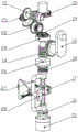
FIG. 2 is a schematic view of the fixing device of the present invention;
FIG. 3 is a schematic view showing the internal structure of the fixing device of the present invention;
FIG. 4 is a schematic diagram showing the matching states of the power structure, the upper clutch structure, the lower clutch structure, the switching structure, the forward rotation structure, the reverse rotation structure and the rotation structure in the present invention;
FIG. 5 is a schematic diagram showing the matching states of the power structure, the upper clutch structure, the lower clutch structure and the switching structure in the present invention;
FIG. 6 is a schematic view showing the engagement state of the forward rotation structure, the reverse rotation structure and the lower worm in the present invention;
FIG. 7 is a schematic diagram showing the cooperation of the forward rotation structure and the reverse rotation structure;
FIG. 8 is a schematic view showing a structure of a rotating structure according to the present invention;
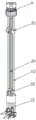
FIG. 9 is a schematic view showing the engagement between the needle insertion structure and the fixing structure in the present invention;
FIG. 10 is a schematic view showing the internal structure of the needle inserting structure and the fixing structure according to the present invention;
FIG. 11 is a schematic view showing the fitting state of the slider and the screw cylinder according to the present invention;
FIG. 12 is a schematic view of the engagement between the driving block and the insertion block;
FIG. 13 is a schematic view showing the engagement between the adjusting block and the self-locking assembly;
FIG. 14 is a schematic structural view of the self-locking assembly of the present invention;
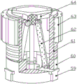
FIG. 15 is a schematic structural view of a fixing structure in the present invention;
FIG. 16 is a schematic view showing the structure of a connection structure in the present invention;
in the figure: 1. a base, 2, a vertical telescopic rod, 3, a connecting structure, 4, a transverse telescopic rod, 5, a fixing device, 6, a fixing structure, 7, a needle inserting structure, 8, a driving rod, 9, a transmission cavity, 10, a connecting rod, 11, a rotating cavity, 12, a crank, 13, a rotating structure, 14, a lower worm wheel, 15, a universal joint, 16, a lower clutch structure, 17, a motor, 18, an upper clutch structure, 19, a first bevel gear set, 20, an upper worm wheel, 21, an upper worm, 22, a second bevel gear set, 23, a third bevel gear set, 24, an upper ratchet wheel, 25, a needle inserting cylinder, 26, a lower ratchet wheel, 27, a U-shaped rod, 28, a pushing block, 29, a driven clutch block, 30, a driving clutch block, 31, a spline, 32, a rotating cylinder, 33, a supporting plate, 34, a traction rod, 35, a traction spring, 36, a lower rotating disc, 37, an upper rotating disc, 38, an upper pawl, 39 and a lower rotating disc, 40. the device comprises a main shaft, 41, a ratchet bar, 42, a sliding block, 43, a guide rod, 44, a screw rod, 45, an adjusting block, 46, a bolt connection cylinder, 47, an insertion block, 48, a driving block, 49, a return spring, 50, a return rod, 51, a driving sliding chute, 52, a pin shaft, 53, an operation block, 54, a guide block, 55, a guiding sliding chute, 56, a rotating block, 57, a clamping rod, 58, an elastic sheet, 59, a clamping block, 60, a supporting block, 61, a connecting cylinder, 62, a clamping rod, 63, a nut, 64, a push rod, 65, a sliding cylinder, 66, an upper supporting plate, 67, a fixing plate, 68, a nut pressing sleeve, 69 and a fixed screw rod.
Detailed Description
An interventional needle fixing device for tumor treatment, as shown in fig. 1-16, comprises a support frame, a fixing device 5 is rotatably connected on the support frame; the fixing device 5 comprises a rotating cavity 11 which is rotatably connected with the support frame, a transmission cavity 9 is connected on the rotating cavity 11, and a needle inlet cylinder 25 is rotatably connected on the transmission cavity 9; a power structure is arranged in the transmission cavity 9, the power structure is connected with an upper clutch structure 18 and a lower clutch structure 16 which are coaxially arranged and have the working state opposite to that of the upper clutch structure 18, and a switching structure for switching the working state of the upper clutch structure 18 and the working state of the lower clutch structure 16 is also arranged in the transmission cavity 9;
the upper clutch structure 18 is connected with a forward rotation structure and a reverse rotation structure corresponding to the forward rotation structure, the forward rotation structure is driven to work by the upper clutch structure 18, and the reverse rotation structure is driven to work by the upper clutch structure 18; the forward rotation structure is connected with a driving structure for driving the needle feeding cylinder 25 to rotate along the transmission cavity 9, and the reverse rotation structure is connected with a rotating structure 13 for driving the rotating cavity 11 to rotate along the supporting frame; the lower clutch structure 16 is connected with a universal joint 15, the universal joint 15 is connected with a needle inserting structure 7, and the needle inserting structure 7 is connected with a fixing structure 6.
When the needle inserting device is used, the working states of the upper clutch structure 18 and the lower clutch structure 16 are switched through the switching structure, and the forward rotation structure and the reverse rotation structure are matched, so that the needle inserting structure 7, the rotation structure 13 and the driving structure respectively act, and the use of power cost can be effectively reduced; rotating-structure 13 and drive structure cooperate and adjust the angle of needle inserting structure 7, and after adjusting, lower clutch structure 16 cooperatees with needle inserting structure 7 and punctures the intervention needle on the fixed knot constructs 6 into the patient internal, through needle inserting structure 7's use, can effectually guarantee the stability of intervention needle.
Further, as shown in fig. 5, the power structure includes a motor 17 fixedly connected to the transmission cavity 9, an output end of the motor 17 is connected to a spline 31, and both the upper clutch structure 18 and the lower clutch structure 16 are slidably connected to the spline 31; the upper clutch structure 18 and the lower clutch structure 16 both comprise a driving clutch block 30 connected with a spline 31 in a sliding manner, and a driven clutch block 29 corresponding to the driving clutch block 30 is rotationally connected in the transmission cavity 9; the motor 17 synchronously drives the driving clutch block 30 to rotate through the spline 31, and the driving clutch block 30 drives the corresponding driven clutch block 29 to rotate according to the meshing with the driven clutch block; through the arrangement of the upper clutch structure 18 and the lower clutch structure 16, the motor 17 drives the needle inserting structure 7 and the corresponding structure for adjusting the angle of the needle inserting structure 7 to act respectively.
Further, as shown in fig. 5, the switching structure includes a U-shaped rod 27, a pushing block 28 is connected to the U-shaped rod 27, and a rotating cylinder 32 rotatably connected to the driving clutch block 30 is connected to both ends of the U-shaped rod 27; a supporting plate 33 is further arranged in the transmission cavity 9, a traction rod 34 is rotatably connected to the supporting plate 33, a traction spring 35 is arranged at one end of the traction rod 34, which is far away from the U-shaped rod 27, and the other end of the traction spring 35 is connected with the middle part of the U-shaped rod 27; the U-shaped rod 27 is connected with the pair of rotary drums 32, the push block 28 and the U-shaped rod 27 are matched to synchronously drive the rotary drums 32 to move towards one direction, one driving clutch block 30 is separated from the driven clutch block 29, the other driving clutch block 30 is closed to the driven clutch block 29, and the operation convenience of the application is improved.
Further, the forward rotation structure comprises a main shaft 40 connected with the driven clutch block 29 of the upper clutch structure 18, and the main shaft 40 is connected with the lower rotating disk 36; a lower ratchet wheel 26 is rotationally connected in the transmission cavity 9, a lower pawl 39 matched with the lower ratchet wheel 26 is rotationally connected on the lower rotating disk 36, and a spring corresponding to the lower pawl 39 is arranged on the lower rotating disk 36; as shown in fig. 2 and 3, the driving structure includes a lower worm coaxially fixed with the lower ratchet 26, and a lower worm wheel 14 engaged with the lower worm is rotatably connected in the transmission cavity 9; the lower worm wheel 14 is coaxially and fixedly connected with a crank 12, the needle feeding cylinder 25 is connected with a driving rod 8, the driving rod 8 is arranged at the rotation center of the needle feeding cylinder 25 and the transmission cavity 9, and the crank 12 is rotatably connected with a connecting rod 10 which is rotatably connected with the driving rod 8. When the driven clutch block 29 rotates forwards, the lower rotating disk 36 is driven to rotate through the main shaft 40, the lower rotating disk 36 drives the lower ratchet wheel 26 to rotate through the lower pawl 39, and the lower ratchet wheel 26 drives the lower worm to rotate; the lower worm drives the crank 12 to rotate through the lower worm wheel 14, and the crank 12 drives the syringe 25 to rotate through the connecting rod 10 and the driving rod 8.
Further, the reverse rotation structure comprises an upper rotating disc 37 fixedly connected with the main shaft 40, an upper ratchet wheel 24 corresponding to the upper rotating disc 37 is rotatably connected in the transmission cavity 9, and the tooth directions of the upper ratchet wheel 24 and the lower ratchet wheel 26 are opposite; an upper pawl 38 matched with the upper ratchet wheel 24 is rotatably connected to the upper rotating disc 37, and a spring corresponding to the upper pawl 38 is arranged on the upper rotating disc 37; as shown in fig. 8, the rotating structure 13 includes a first bevel gear set 19 coaxially fixed to the upper ratchet 24, and a second bevel gear set 22 is connected to an output end of the first bevel gear set 19; the output end of the second bevel gear set 22 is connected with a third bevel gear set 23, the output end of the third bevel gear set 23 is connected with an upper worm 21, and an upper worm wheel 20 meshed with the upper worm 21 is fixedly connected to the support frame. When the driven clutch block 29 rotates reversely, the upper rotating disc 37 is driven to rotate through the main shaft 40, the upper rotating disc 37 drives the first bevel gear set 19 to move through the upper pawl 38 and the upper ratchet wheel 24, the first bevel gear set 19 drives the upper worm 21 to rotate through the second bevel gear set 22 and the third bevel gear set 23, and the upper worm 21 drives the rotating cavity 11 to rotate along the upper worm gear 20 as the upper worm gear 20 is fixedly connected with the support frame; at the same time, the lower pawl 39 slides along the back of the lower ratchet 26; namely, the upper ratchet wheel 24 and the upper pawl 38 are matched with the lower ratchet wheel 26 and the lower pawl 39 for use, so that the motor 17 drives the driving structure to act when rotating forwards, and the motor 17 drives the rotating structure 13 to act when rotating backwards, namely, the angle of the needle feeding cylinder 25 is adjusted through the forward and reverse rotation of the motor 17, and the use of a power structure is reduced.
Further, as shown in fig. 10 and 11, the needle inserting structure 7 includes a screw 44 connected to the universal joint 15, and a screw cylinder 46 is screwed on the screw 44; the screw cylinder 46 is rotatably connected with a sliding block 42, the sliding block 42 is connected with a guide rod 43, and the guide rod 43 is connected with the fixed structure 6; the slide block 42 is connected with a reset rod 50 in a sliding manner, the reset rod 50 is connected with an insert block 47, the reset rod 50 is also provided with a reset spring 49 matched with the insert block 47, and the bolt connection barrel 46 is provided with a slot matched with the insert block 47; the slide block 42 is also connected with a driving block 48 corresponding to the inserting block 47 in a sliding manner, the driving block 48 is provided with a driving chute 51 with a V-shaped structure, and the inserting block 47 is provided with a pin shaft 52 matched with the driving chute 51; the needle feeding cylinder 25 is connected with an adjusting block 45 corresponding to the driving block 48 in a sliding mode, and the needle feeding cylinder 25 is provided with a self-locking assembly corresponding to the adjusting block 45.
When the needle inserting structure 7 is used, the adjusting block 45 is adjusted according to the length of an interventional needle and the puncture depth, and the adjusting block 45 is locked by using a self-locking assembly; the screw rod 44 drives the sliding block 42 to slide through the screw connection cylinder 46 and the insertion block 47, and the sliding block 42 drives the fixing structure 6 and the intervention needle to puncture through the guide rod 43; when the driving block 48 is in contact with the adjusting block 45, the driving block 48 slides along the sliding block 42, the driving block 48 drives the inserting block 47 to slide along the sliding block 42 through the matching of the driving sliding groove 51 and the pin shaft 52, so that the inserting block 47 is separated from the inserting groove, the screw rod 44 drives the screw connecting cylinder 46 to rotate, and the sliding block 42 is not moved; through adjusting block 45's setting, can effectually carry out spacingly to the intervention degree of depth of interveneeing the needle, improve the security of this application.
Further, as shown in fig. 13 and 14, the self-locking assembly includes a guide block 54 fixedly connected to the adjusting block 45, and a rotating block 56 is rotatably connected to the guide block 54; a clamping rod 57 is arranged on the rotating block 56, and a ratchet bar 41 matched with the clamping rod 57 is arranged on the needle inlet cylinder 25; the clamping rod 57 is connected with an operation block 53, and the guide block 54 is provided with a guide sliding groove 55 matched with the clamping rod 57; the guide block 54 is provided with a spring plate 58, and the rotating block 56 is provided with a front clamping groove matched with the spring plate 58 and a rear clamping groove corresponding to the front clamping groove; the adjusting block 45 is locked by the matching of the ratchet rack 41 and the clamping rod 57; when the adjusting block 45 is locked, the elastic sheet 58 is positioned in the front clamping groove, as shown in fig. 14; when the regulating block 45 needs to be moved, the clamping rod 57 is driven to rotate along the guide sliding groove 55 through the operating block 53, so that the elastic sheet 58 is positioned in the rear clamping groove, the clamping rod 57 can be effectively prevented from rotating due to the action of the elastic sheet 58 when the regulating block 45 is moved, and the convenience in operation of the application is improved.
Further, as shown in fig. 15, the fixing structure 6 includes a connecting cylinder 61 connected to the guide rod 43, and the supporting block 60 is connected to the connecting cylinder 61; a fixing hole is formed in the supporting block 60, and a plurality of clamping blocks 59 corresponding to the fixing hole are connected to the supporting block 60 in a sliding mode; a nut 63 is screwed on the connecting cylinder 61, a push rod 64 connected with the connecting cylinder 61 in a sliding manner is rotatably connected on the nut 63, a plurality of clamping rods 62 are rotatably connected on the push rod 64, and the other ends of the clamping rods 62 are rotatably connected with the clamping blocks 59; fixed knot constructs 6 and will intervene the needle and put into the fixed orifices when fixed to intervene the needle, rotates nut 63, and nut 63 passes through push rod 64, holding rod 62 and drives grip block 59 and slide along supporting shoe 60, and grip block 59 carries out the centre gripping to intervene the needle, and this fixed knot constructs 6 can adapt to the intervention needle of different thicknesses, improves the practicality of this application.
Further, as shown in fig. 1, the support frame includes a base 1, and a universal wheel with a service brake is arranged on the base 1; the base 1 is provided with a vertical telescopic rod 2, the transverse telescopic rod 4 and the vertical telescopic rod 2 are both electric telescopic rods, and the vertical telescopic rod 2 is connected with a connecting structure 3 in a sliding manner; the telescopic end of the vertical telescopic rod 2 is connected with a transverse telescopic rod 4, and an upper worm wheel 20 is fixedly connected with the telescopic end of the transverse telescopic rod 4; transversely adjust fixing device 5 through horizontal telescopic link 4, adjust fixing device 5's vertical through vertical telescopic link 2, fix this application on the puncture bed through connection structure 3.
Further, as shown in fig. 16, the connecting structure 3 includes a sliding cylinder 65 slidably connected to the vertical telescopic rod 2, the sliding cylinder 65 is provided with a fastening screw corresponding to the vertical telescopic rod 2, and the sliding cylinder 65 is connected to a connecting plate; two ends of the connecting plate are respectively connected with an upper supporting plate 66 and a lower supporting plate 33 corresponding to the upper supporting plate 66, the lower supporting plate 33 is rotatably connected with a fixed screw rod 69, a knob is arranged on the fixed screw rod 69, and a nut pressing sleeve 68 is screwed on the fixed screw rod 69; a fixing plate 67 matched with the upper supporting plate 66 is fixedly connected to the nut pressing sleeve 68, and the fixing plate 67 is connected with the connecting plate in a sliding mode; connection structure 3 drives fixed screw 69 through the knob and rotates when using, and fixed screw 69 passes through the screw and presses cover 68 to drive fixed plate 67 to slide along the connecting plate, realizes fixing this application on the puncture bed.
The working process of the invention is as follows:
when the puncture outfit is used, the puncture outfit is moved to the side of a puncture bed through the base 1 and the universal wheels; according to the angle of the patient needing puncturing, the pushing block 28 and the U-shaped rod 27 are matched to synchronously drive the rotating cylinder 32 to move upwards, the U-shaped rod 27 drives the driving clutch block 30 on the upper clutch structure 18 to be meshed with the driven clutch block 29, and the driving clutch block 30 of the lower clutch mechanism is separated from the driven clutch block 29; the motor 17 rotates forwards, the motor 17 drives the driving clutch block 30 to rotate through the spline 31, and the driving clutch block 30 drives the main shaft 40 to rotate through the driven clutch block 29; the main shaft 40 drives the lower rotating disk 36 to rotate, the lower rotating disk 36 drives the lower ratchet wheel 26 to rotate through the lower pawl 39, and the lower ratchet wheel 26 drives the lower worm to rotate; the lower worm drives the crank 12 to rotate through the lower worm wheel 14, and the crank 12 drives the syringe 25 to rotate through the connecting rod 10 and the driving rod 8.
When the motor 17 rotates reversely, the upper rotating disc 37 is driven to rotate by the main shaft 40, the upper rotating disc 37 drives the first bevel gear set 19 to act by the upper pawl 38 and the upper ratchet wheel 24, the first bevel gear set 19 drives the upper worm 21 to rotate by the second bevel gear set 22 and the third bevel gear set 23, and the upper worm 21 drives the rotating cavity 11, the transmission cavity 9 and the needle inserting cylinder 25 to rotate along the upper worm gear 20 as the upper worm gear 20 is fixedly connected with the support frame; at the same time, the lower pawl 39 slides along the back of the lower ratchet 26; drive solid fixed screw 69 through the knob and rotate, gu fixed screw 69 passes through screw pressure cover 68 and drives fixed plate 67 and slide along the connecting plate, realizes fixing this application on the puncture bed.
Putting the interventional needle into the fixing hole, rotating the nut 63, driving the clamping block 59 to slide along the supporting block 60 by the nut 63 through the push rod 64 and the clamping rod 62, and clamping the interventional needle by the clamping block 59; the adjusting block 45 is adjusted according to the length of the interventional needle and the puncture depth, and the operation block 53 drives the clamping rod 57 to rotate along the guide sliding groove 55, so that the elastic sheet 58 is positioned in the rear clamping groove; the clamping rod 57 is moved to a corresponding position, and the adjusting block 45 is fixed between the clamping rod 57 and the adjacent ratchet teeth by rotating; the pushing block 28 and the U-shaped rod 27 are matched to synchronously drive the rotating drum 32 to move downwards, the U-shaped rod 27 drives the driving clutch block 30 on the lower clutch structure 16 to be meshed with the driven clutch block 29, and the driving clutch block 30 of the upper clutch mechanism is separated from the driven clutch block 29.
The motor 17 drives the universal joint 15 to rotate through the spline 31, the driving clutch block 30 and the driven clutch block 29, and the universal joint 15 drives the screw rod 44 to rotate; the screw rod 44 drives the sliding block 42 to slide through the screw connection cylinder 46 and the insertion block 47, and the sliding block 42 drives the fixing structure 6 and the intervention needle to puncture through the guide rod 43; when the driving block 48 is in contact with the adjusting block 45, the driving block 48 slides along the sliding block 42, the driving block 48 drives the inserting block 47 to slide along the sliding block 42 through the matching of the driving sliding groove 51 and the pin shaft 52, so that the inserting block 47 is separated from the inserting groove, the screw rod 44 drives the screw connecting cylinder 46 to rotate, and the sliding block 42 is fixed.
Claims (10)
1. The utility model provides a tumour treatment is with interveneeing needle fixing device which characterized in that: comprises a supporting frame, wherein a fixing device (5) is rotatably connected on the supporting frame; the fixing device (5) comprises a rotating cavity (11) which is rotatably connected with the support frame, a transmission cavity (9) is connected on the rotating cavity (11), and a needle feeding cylinder (25) is rotatably connected on the transmission cavity (9); a power structure is arranged in the transmission cavity (9), an upper clutch structure (18) and a lower clutch structure (16) which are coaxially arranged are connected to the power structure, the working state of the upper clutch structure (18) is opposite to that of the lower clutch structure (16), and a switching structure for switching the working state of the upper clutch structure (18) and the working state of the lower clutch structure (16) is further arranged in the transmission cavity (9);
the upper clutch structure (18) is connected with a forward rotation structure and a reverse rotation structure corresponding to the forward rotation structure, the forward rotation of the upper clutch structure (18) drives the forward rotation structure to work, and the reverse rotation of the upper clutch structure (18) drives the reverse rotation structure to work; the forward rotation structure is connected with a driving structure which drives the needle inlet cylinder (25) to rotate along the transmission cavity (9), and the reverse rotation structure is connected with a rotation structure (13) which drives the rotation cavity (11) to rotate along the support frame; the lower clutch structure (16) is connected with a universal joint (15), the universal joint (15) is connected with a needle inserting structure (7), and the needle inserting structure (7) is connected with a fixing structure (6).
2. The interventional needle fixing device for tumor therapy according to claim 1, wherein: the power structure comprises a motor (17) fixedly connected with the transmission cavity (9), the output end of the motor (17) is connected with a spline (31), and the upper clutch structure (18) and the lower clutch structure (16) are in sliding connection with the spline (31); the upper clutch structure (18) and the lower clutch structure (16) both comprise a driving clutch block (30) in sliding connection with the spline (31), and a driven clutch block (29) corresponding to the driving clutch block (30) is rotationally connected in the transmission cavity (9).
3. The interventional needle fixing device for tumor treatment as set forth in claim 2, wherein: the switching structure comprises a U-shaped rod (27), a push block (28) is connected to the U-shaped rod (27), and two ends of the U-shaped rod (27) are connected with a rotating drum (32) which is rotatably connected with the driving clutch block (30); the transmission cavity (9) is also internally provided with a supporting plate (33), the supporting plate (33) is rotatably connected with a traction rod (34), one end of the traction rod (34) far away from the U-shaped rod (27) is provided with a traction spring (35), and the other end of the traction spring (35) is connected with the middle part of the U-shaped rod (27).
4. The interventional needle fixing device for tumor therapy according to any one of claims 2 or 3, wherein: the forward rotation structure comprises a main shaft (40) connected with a driven clutch block (29) of the upper clutch structure (18), and the main shaft (40) is connected with a lower rotating disc (36); the transmission cavity (9) is rotatably connected with a lower ratchet wheel (26), the lower rotating disk (36) is rotatably connected with a lower pawl (39) matched with the lower ratchet wheel (26), and a spring corresponding to the lower pawl (39) is arranged on the lower rotating disk (36).
5. The interventional needle fixing device for tumor therapy according to claim 4, wherein: the driving structure comprises a lower worm coaxially and fixedly connected with a lower ratchet wheel (26), and a lower worm wheel (14) meshed with the lower worm is rotationally connected in the transmission cavity (9); the lower worm wheel (14) is coaxially and fixedly connected with a crank (12), the needle inlet cylinder (25) is connected with a driving rod (8), and the crank (12) is rotatably connected with a connecting rod (10) rotatably connected with the driving rod (8).
6. The interventional needle fixing device for tumor therapy according to any one of claims 2 or 5, wherein: the reverse rotation structure comprises an upper rotating disc (37) fixedly connected with the main shaft (40), an upper ratchet wheel (24) corresponding to the upper rotating disc (37) is rotatably connected in the transmission cavity (9), and the tooth directions of the upper ratchet wheel (24) and the lower ratchet wheel (26) are opposite; the upper rotating disc (37) is rotatably connected with an upper pawl (38) matched with the upper ratchet wheel (24), and the upper rotating disc (37) is provided with a spring corresponding to the upper pawl (38).
7. The interventional needle fixing device for tumor therapy according to claim 6, wherein: the rotating structure (13) comprises a first bevel gear set (19) coaxially and fixedly connected with an upper ratchet wheel (24), and the output end of the first bevel gear set (19) is connected with a second bevel gear set (22); the output end of the second bevel gear set (22) is connected with a third bevel gear set (23), the output end of the third bevel gear set (23) is connected with an upper worm (21), and an upper worm wheel (20) meshed with the upper worm (21) is fixedly connected to the support frame.
8. The interventional needle fixing device for tumor treatment as set forth in claim 2, wherein: the needle inserting structure (7) comprises a screw rod (44) connected with the universal joint (15), and a screw connecting cylinder (46) is screwed on the screw rod (44); the screw connecting cylinder (46) is rotatably connected with a sliding block (42), the sliding block (42) is connected with a guide rod (43), and the guide rod (43) is connected with the fixed structure (6); the sliding block (42) is connected with a reset rod (50) in a sliding mode, the reset rod (50) is connected with an insert block (47), a reset spring (49) matched with the insert block (47) is further arranged on the reset rod (50), and a slot matched with the insert block (47) is formed in the bolt connection barrel (46); the sliding block (42) is also connected with a driving block (48) corresponding to the inserting block (47) in a sliding manner, a driving sliding groove (51) with a V-shaped structure is formed in the driving block (48), and a pin shaft (52) matched with the driving sliding groove (51) is formed in the inserting block (47); the needle feeding cylinder (25) is connected with a regulating block (45) corresponding to the driving block (48) in a sliding mode, and the needle feeding cylinder (25) is provided with a self-locking assembly corresponding to the regulating block (45).
9. The interventional needle fixing device for tumor therapy according to claim 8, wherein: the self-locking assembly comprises a guide block (54) fixedly connected with the adjusting block (45), and a rotating block (56) is rotatably connected to the guide block (54); a clamping rod (57) is arranged on the rotating block (56), and a ratchet rack (41) matched with the clamping rod (57) is arranged on the needle inlet cylinder (25); the clamping rod (57) is connected with an operation block (53), and the guide block (54) is provided with a guide sliding groove (55) matched with the clamping rod (57); the guide block (54) is provided with an elastic sheet (58), and the rotating block (56) is provided with a front clamping groove matched with the elastic sheet (58) and a rear clamping groove corresponding to the front clamping groove.
10. The interventional needle fixing device for tumor therapy according to claim 9, wherein: the fixing structure (6) comprises a connecting cylinder (61) connected with the guide rod (43), and a supporting block (60) is connected to the connecting cylinder (61); the supporting block (60) is provided with a fixing hole, and the supporting block (60) is connected with a plurality of clamping blocks (59) corresponding to the fixing hole in a sliding manner; the connecting cylinder (61) is connected with a nut (63) in a threaded mode, a push rod (64) connected with the connecting cylinder (61) in a sliding mode is connected to the nut (63) in a rotating mode, a plurality of clamping rods (62) are connected to the push rod (64) in a rotating mode, and the other end of each clamping rod (62) is connected with a clamping block (59) in a rotating mode.
Priority Applications (1)
| Application Number | Priority Date | Filing Date | Title |
|---|---|---|---|
| CN202110763261.9A CN113440228A (en) | 2021-07-06 | 2021-07-06 | Interventional needle fixing device for tumor treatment |
Applications Claiming Priority (1)
| Application Number | Priority Date | Filing Date | Title |
|---|---|---|---|
| CN202110763261.9A CN113440228A (en) | 2021-07-06 | 2021-07-06 | Interventional needle fixing device for tumor treatment |
Publications (1)
| Publication Number | Publication Date |
|---|---|
| CN113440228A true CN113440228A (en) | 2021-09-28 |
Family
ID=77815186
Family Applications (1)
| Application Number | Title | Priority Date | Filing Date |
|---|---|---|---|
| CN202110763261.9A Withdrawn CN113440228A (en) | 2021-07-06 | 2021-07-06 | Interventional needle fixing device for tumor treatment |
Country Status (1)
| Country | Link |
|---|---|
| CN (1) | CN113440228A (en) |
Citations (7)
| Publication number | Priority date | Publication date | Assignee | Title |
|---|---|---|---|---|
| DE3108766A1 (en) * | 1981-03-07 | 1982-09-23 | GMS, Gesellschaft für medizinische Sondentechnik mbH, 2300 Kiel | Medical puncture probe measuring device |
| CN103386928A (en) * | 2012-07-04 | 2013-11-13 | 江苏理工学院 | Intelligent Adjustment System of Automobile Rearview Mirror |
| CN104196917A (en) * | 2014-08-25 | 2014-12-10 | 中科华核电技术研究院有限公司 | Backstop device and control rod driving mechanism provided with same |
| CN106195895A (en) * | 2016-08-22 | 2016-12-07 | 平阳创迷电子商务有限公司 | A kind of rotating street lamp |
| CN111588466A (en) * | 2020-05-15 | 2020-08-28 | 上海导向医疗系统有限公司 | Accurate automatic puncture system |
| CN111820954A (en) * | 2020-07-24 | 2020-10-27 | 纪翠霞 | An obstetric amniotic fluid detection and sampling device |
| US20210000499A1 (en) * | 2019-07-04 | 2021-01-07 | Aaron Fenster | Biopsy apparatus |
-
2021
- 2021-07-06 CN CN202110763261.9A patent/CN113440228A/en not_active Withdrawn
Patent Citations (7)
| Publication number | Priority date | Publication date | Assignee | Title |
|---|---|---|---|---|
| DE3108766A1 (en) * | 1981-03-07 | 1982-09-23 | GMS, Gesellschaft für medizinische Sondentechnik mbH, 2300 Kiel | Medical puncture probe measuring device |
| CN103386928A (en) * | 2012-07-04 | 2013-11-13 | 江苏理工学院 | Intelligent Adjustment System of Automobile Rearview Mirror |
| CN104196917A (en) * | 2014-08-25 | 2014-12-10 | 中科华核电技术研究院有限公司 | Backstop device and control rod driving mechanism provided with same |
| CN106195895A (en) * | 2016-08-22 | 2016-12-07 | 平阳创迷电子商务有限公司 | A kind of rotating street lamp |
| US20210000499A1 (en) * | 2019-07-04 | 2021-01-07 | Aaron Fenster | Biopsy apparatus |
| CN111588466A (en) * | 2020-05-15 | 2020-08-28 | 上海导向医疗系统有限公司 | Accurate automatic puncture system |
| CN111820954A (en) * | 2020-07-24 | 2020-10-27 | 纪翠霞 | An obstetric amniotic fluid detection and sampling device |
Similar Documents
| Publication | Publication Date | Title |
|---|---|---|
| CN115068188A (en) | Orthopedics-based auxiliary traction device for orthopedics doctor | |
| CN117883154A (en) | A single body puncture depth control mechanism and control driving mechanism thereof | |
| CN113440228A (en) | Interventional needle fixing device for tumor treatment | |
| CN112057223B (en) | Lumbar disc herniation treatment device | |
| CN201841521U (en) | Device for assembling spring on spring shaft | |
| DE102004006368A1 (en) | linear unit | |
| CN213189991U (en) | CT puncture guide | |
| CN210750622U (en) | Infusion device for severe burns | |
| CN220558157U (en) | Orthopedics external fixation support | |
| CN221759076U (en) | Anti-deformation flat press for adhesive tape production | |
| CN217119052U (en) | Micro-injection pump | |
| CN217090790U (en) | Ratchet transmission type stepless automatic adjustment surgical retractor | |
| CN213489190U (en) | Clinical piercing depth of cardiovascular internal medicine | |
| CN213310687U (en) | Traction bed | |
| CN211214276U (en) | Vertebra nursing device | |
| CN213372348U (en) | Puncture needle structure for cardiology | |
| CN114916266A (en) | Portable intelligent rooter | |
| CN109157316B (en) | Leg fracture tractor | |
| CN221512043U (en) | Multi-part hemostat for hematology department | |
| CN223009300U (en) | Tongue blocking device for orthodontics | |
| CN221411895U (en) | Injection positioner that obstetrical operation anesthesia was used | |
| CN222055680U (en) | Animal doctor struts ware with domestic animals oral cavity | |
| CN220277864U (en) | Seamless steel tube sizing structure | |
| CN215193053U (en) | Medical treatment operation flatcar | |
| CN217608435U (en) | Pushing type forage grass bundling equipment gradually |
Legal Events
| Date | Code | Title | Description |
|---|---|---|---|
| PB01 | Publication | ||
| PB01 | Publication | ||
| SE01 | Entry into force of request for substantive examination | ||
| SE01 | Entry into force of request for substantive examination | ||
| WW01 | Invention patent application withdrawn after publication |
Application publication date: 20210928 |
|
| WW01 | Invention patent application withdrawn after publication |