Detailed Description
Fig. 1 is an illustration of a patient 102 wearing a scalp cap 104 for use with a cooling system. The scalp cap 104 may be silicon or other material that is thermally conductive, but is a single piece of material without cuts or trim lines. Because the nature of the material does not conform to the patient's scalp, the scalp cap 104 does not allow for a full fit. The shape of the patient's scalp can present problems when constructing the scalp cap 104 according to one size that fits all models. To provide effective cooling, the scalp cap 104 must maintain maximum contact with the patient's scalp, which is not possible with a normal or fixed set of scalp cap 104 versions because each patient 102 has a unique scalp contour. With existing designs, the temperature difference between the scalp and the scalp cap 104 can exceed eighteen (18) degrees celsius.
Fig. 2 is an illustration of a patient 202 with a thermal cap 206 (or intermediate covering) used with a cooling system in at least one embodiment. The thermal cap 206 may be constructed of a heat resistant or heat reflective material such as cotton, ceramic, fiberglass, aluminized, silicone, silica, aramid, vermiculite, Z-block, acrylic, PTFE fabric, or impregnated fabric. In at least one embodiment, the thermal cap 206 is made of cotton or other fabric. The patient 202 may use the thermal cap 206 to prevent or reduce the amount of cooling lost to the room. For example, the hot cap 206 may be used to increase the cooling effect of the cooling system and a headgear (not shown).
Fig. 3A is an illustration of a patient 302 applying a stationary cap 308 (or external scalp covering) on a hot cap (not shown) and/or scalp cap (not shown) for use with a cooling system. The retaining cap 308 may include at least one retaining mechanism 310 to increase pressure on the thermal cap (not shown) and/or scalp cap (not shown). The at least one securing mechanism 310 may utilize a securing wire 311, and the securing wire 311 may be tightened or released by the at least one securing mechanism. In some embodiments, at least one securing mechanism 310 can be pressed or knocked in and rotated to tighten the securing wire 311, and at least one securing mechanism 310 can be pulled or knocked out to loosen the securing wire 311. In other embodiments, the at least one securing mechanism 310 can be pulled or knocked out and rotated to tighten the securing wire 311, and the at least one securing mechanism 310 can be pressed or knocked in to loosen the securing wire 311. In at least one example, retaining cap 308 applies pressure or a fixed pressure to a thermal cap (not shown) and a scalp cap (not shown) to ensure that the scalp cap is as close to and/or maintains as much contact with the scalp as possible to increase the amount of cooling of the patient's scalp and/or hairline.
Fig. 3B is an illustration of a patient 302 securing a retaining cap 308 (or outer covering) on a hot cap (not shown) and/or scalp cap (not shown) for use with a cooling system. In at least one form, the retaining cap 308 can include a plurality of retaining mechanisms 310. The securing mechanism 310 may provide for engagement or disengagement of the patient 302 with the securing mechanism, which may include tightening or loosening of the thermal cap (not shown) and/or scalp cap (not shown) by the securing cap 308. The at least one securing mechanism 310 may utilize a securing wire 311 that may be tightened or released by the at least one securing mechanism. In some embodiments, at least one fixation mechanism 310 may have a knob that can be pressed or knocked in and rotated to tighten the fixation wire 311, and at least one fixation mechanism 310 may have a knob that can be pulled or knocked out to loosen the fixation wire 311. In other embodiments, at least one fixation mechanism 310 may have a knob that can be pulled or knocked out and rotated to tighten fixation wire 311, and at least one fixation mechanism 310 may have a knob that can be pressed or knocked in to loosen fixation wire 311. In some embodiments, the securing cap 308 may have a chin strap 301 or a connecting strap. The chin strap 301 may have a buckle 303 or other fastening mechanism such as, but not limited to, buttons, clips, straps, or hook and loop fastening mechanisms.
Fig. 4A is an illustration of a perspective view angled retaining
cap 408. Fig. 4B is an illustration of the securing
cap 408 from a side view angle. With respect to fig. 4A and 4B, the patient 402 may place the securing
cap 408 on the head for securing and/or applying pressure to other caps below the securing
cap 408. In at least one form, the securing
cap 408 can include at least two securing
mechanisms 410. The at least two
fixation mechanisms 410 may be placed on the left side 403A and the right side 403A of the patient's head. The
securing mechanism 410 may be placed on a
securing pad 412. The
securing pad 412 may provide for displacement of the
securing mechanism 410 when the
securing mechanism 410 is engaged or disengaged. This displacement allows for variations in the contour or size of the head of the patient 402, allowing the retaining
cap 408 and/or the
retaining mechanism 410 to provide a secure and comfortable fit. In at least one example, the
securing mechanism 410 may be
The ratchet mechanism of brand.
The securing mechanisms 410 may each have a securing wire 414 passing through securing rings 416A, 416B, 416C, 416D, and/or 416E (collectively 416). The securing ring 416 may be attached by threads, fasteners (such as, but not limited to, hooks and loops), glue, adhesive, or other similar and similar methods of attachment and/or connection to the securing cap 408. There may be additional retaining rings 416 or fewer retaining rings 416 based on the size and/or position of the retaining mechanism 410 relative to the retaining cap 408. In at least one form of the securing cap 408, a strap retainer 418 and/or chin strap 420 can be utilized to increase the safety of the securing cap 408. The strap mount 418 and/or chin strap 420 may allow adjustability of the securing cap 408 under the chin and/or around the face of the patient.
Fig. 5A is a perspective view of a scanned header 522 used in the parameterization process 500A. In at least one version of the parameterization process 500A, at least one axis is provided. Axes 524A, 524B and/or 524C provide a reference for the size of the scanned patient's head. The scan may be performed using a 3D scanner, an image of the patient, X-rays, CAT scan, MIR imaging, or other imaging and/or measurement methods.
Fig. 5B is a side view of scanned head 522 used for parameterization process 500B. In at least one version of the parameterization process 500B, at least one axis is provided. Axes 524D and/or 524E provide a reference for the size of the patient's head being scanned. A parameterized model may be developed from the scanned header 522. During development of the parameterized model, the user may rotate or change the perspective of the scanned head 522 to allow different details to be seen or analyzed. With respect to fig. 5A and 5B, a process may be utilized to transform an image, set of images, or imaging output for use with a process that allows for the creation of a personalized scalp cap (not shown). For example, the data may be in a format such as, but not limited to, Comma Separated Values (CSV), or excel format XSL or XSLX, or other data formats for a particular program or system, such as a 3D or three-dimensional scanner. If the scan provides data in an unavailable format, a program that can convert or transform the data into an available format must be used. Any computer, processor, or computing device can be utilized to generate, create, process, and/or develop parameterized models.
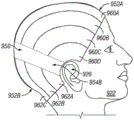
Fig. 6 is a side view illustration of a scanned head 622 for parameterization process 600. In at least one version, the parameterization process 600 may include establishing a hairline for the scanned head 622 and may include a neck line 628A and brow line 628B (collectively 628) that personalize the scalp cap (not shown). Some other factors to consider are the creation of ear cutouts 630 to allow a scalp cap (not shown) to fit snugly over and/or behind the patient's ear 626. The neck line 628A and brow line 628B and ear cutouts 630 may be calculated and/or generated by a computing device, processor, or program. In some examples, one or more of the cervical line 628A, the brow line 628B, or the ear cutouts 630 may be manually selected, and the remainder calculated and/or generated by a computing device, processor, or program. In at least one embodiment, the computing device, processor or program automatically determines and/or calculates the cervical line 628A, brow line 628B, and ear cutouts 630 based on data provided during the scanning or parameterization processing step. A Graphical User Interface (GUI) may be used to illustrate the determinations and/or calculations performed by the computing device, processor or program. In the event that the determination and/or calculation is incorrect due to problems with data provided to the computing device, processor, or program, or problems from abnormal scalp or head contours, the GUI and/or computing device, processor, or program may allow the physician or user to select one or more of the cervical line 628A, brow line 628B, and/or ear cut 630 to manually adjust or reset these lines. If the lines have been adjusted and/or reset, all remaining lines may be determined and/or calculated again by the computing device, processor, or program.
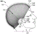
Fig. 7 is a side view illustration of a scanned head 722 for parameterization process 700. After the hairline 728 and ear cut 730 around and/or behind the ear 726 are generated, a polar grid 732 may be generated. The polar grid 732 allows for meridians (longitudinal lines) 734A, 734B, 734C (collectively 734) and latitudes (latitudinal lines) 736A, 736B, 736C (collectively 736). Warp 734 and weft 736 allow for conversion from a parameterization process to polar coordinates and incorporate any variations and/or differences in scanned head 722. Polar coordinates also allow a parameterized model to follow the curvature of the human head. In at least one version, the parameterization process 700 generates a parameterized model that sets the meridian 734 at a fixed angle from the centroid point 735, and the latitudes at a fixed distance 733 from each other (starting from the centroid point 735). In at least one example, the center of mass point 735 can be the center of the ear 726. While in other examples, the center of mass point 735 may be offset from the ear 726. In some versions, the warp 734 and/or the weft 736 may include or be generated from a finite element method analysis and/or finite element method mesh. In other versions, dimensional analysis may be used to generate a parameterized model of the scanned head 722.
Fig. 8 is an illustration of a scanned head 822 for parameterization process 800. After the parameterized model has been generated, the overlay 839 may be generated from the parameterized model. The cover 839 may provide brow lines 838A, neck lines 838B, and/or connecting lines 840 from the ears 826 of the patient or scanned head 822 to the opposite ears (not shown). The interpolated or modified parameterized model may be remapped to a fixed value line or connecting line 840 using an angle variable 841, generating a set of equidistant lines or sections. The pitch of the lines or portions may be calculated so that the variation in line spacing is less than the provided value. The change value may also be used to set the connecting line 840, which in at least one version may be set closer to the cervical line 838B than the brow line 838A. In at least one example, the covering can further include forward radial portions 842A, 842B, 842C, and/or 842D (collectively 842), and/or rearward radial portions 844A, 844B, 844C, and/or 844D (collectively 844). Overlay 839 may also be an interpolated remap of the parameterized model. The overlay 839 may then be used to generate a design file. The design file may be generated automatically by a computing device, processor, or program, or may be semi-automatically generated by some selection by a physician or other user. In some examples, the covering 839 may be calculated and/or generated based on the position of the x-axis and/or symmetry around the x-axis.
FIG. 9A is an illustration of design file output 951 from parameterization process 900A. In at least one version, design file output 951 may include a connection section 950, a front central section 952A, a rear central section 952B, a first set of forward radial sections 958A, 958B, 958C, and/or 958D (collectively 958), a second set of forward radial sections 960A, 960B, 960C, and/or 960D (collectively 960), a first set of rearward radial sections 956A, 956B, and/or 956C (collectively 956), and a second set of radial sections 962A, 962B, and/or 962C (collectively 962). Design file output 951 may be generated from an interpolated parameterized model or a modified parameterized model. The lower clearance angle 949 and/or the upper clearance angle 947 may be calculated for the forward radial portion and the aft radial portion to allow for proper division and interaction of the various portions.
The connecting portion 950 may have a first end 954A and a second end 954B that are distal to each other. In at least one version, the side of the first end 954A is connected to the connecting portion, and the radius opposite that side may be set during one of the processing steps to provide a suitable radial angle to allow for ear cutouts. The first end 954A may also be connected to a first forward radial portion 958A of the first set of forward radial portions 958 and/or a first rearward radial portion 956A of the first set of rearward radial portions 956. Similarly, the side of the second end 954B that is, or is connected to, the connecting portion, the radius opposite that side may be set during one of the processing steps to provide the proper radial angle to allow for the ear cutouts. The second end 954B may also be connected to the first forward radial portion 960A of the second set of forward radial portions 960 and/or the first rearward radial portion 962A of the second set of rearward radial portions 962.
The first set of forward radial portions 958, the second set of forward radial portions 960, and the forward central portion 952A may be connected to the connecting portion 950 by threads, fasteners such as, but not limited to, hooks and loops, glue, adhesive, or other similar or similar attachment and/or connecting methods. Similarly, the first set of rearward radial portions 956, the second set of rearward radial portions 962, and the rear central portion 952B may be connected to the connecting portion 950 by threads, fasteners such as, but not limited to, hooks and loops, glue, adhesive, or other similar or similar attachment and/or connecting methods.
Fig. 9B is an illustration of design file output 951 from parameterization 900A placed on the head of patient 922. Design file output 951 may also be exported to a printer, a printer (stamp), a 3D printer, a fabric, sewing, heat or high frequency welding, and/or other methods or processes for manufacturing or creating headgear. The connecting portion 950 may connect a set of forward radial portions 960A, 960B, 960C, and/or 960D (collectively 960) with a set of rearward radial portions 962A, 962B, and/or 962C (collectively 962). The end 954B of the connecting portion 950 allows for a first forward radial portion 960D, and a first rearward radial portion 962A to appropriately allow for an incision around the ear 926 of the patient 922. The radial portions 960/962 may fit together or with the connecting portion 950 to provide a unique and/or personalized fit for each patient 922. In at least one version, each of the radial portion 960/962, the central portion 952, and the connecting portion 950 may have cooling channels therethrough. Cooling channels may be used for each individual section, each section having its own input and output, while in other embodiments there may be one single channel, with a portion of the channel dedicated to each section. In at least one example, the fluid will flow from the inlet at the right rear side through the channel at the right rear side of the scalp cap, then through the channel at the right side of the scalp cap, then through the channel at the top of the scalp cap, then through the channel at the left side of the scalp cap, then through the channel at the left rear side of the scalp cap, and then out the outlet at the left side of the rear of the scalp cap.
Fig. 9C is an illustration of scalp cap 905 generated from a parameterization process. The scalp cap 905 may have at least one cooling channel (collectively 951), shown as cooling channel input 951A and cooling channel output 951B. The cooling channel 951 allows cooling fluid 953 to flow and/or be pumped through the scalp cap 905. The rearward radial portions 956A, 956B and/or 956C (collectively 956), the forward radial portions 958A, 958B and/or 958C (collectively 958), the forward central portion 952A and the rearward central portion 952B may each have their own independent cooling channels, which may intersect and/or connect to the previous portion, or fluidly connect to the cooling channel input and/or cooling channel output 951. The portions 952, 956 and/or 958, respectively, may each be individually separated by a cutting or separating channel 955, which cutting or separating channel 955 allows each individual portion to increase the tightness with the scalp. The cutting or separating channel 955 can be a point or portion along the scalp cap 905 in which one or more portions are separated, including but not limited to a separation such as shown by the upper clearance angle 947 of fig. 9A. The central connection channel 950 may allow the front and rear portions to align with and conform to the scalp and/or head of a patient, respectively. Scalp cap 905 allows for a temperature difference between the scalp and scalp cap 905 of less than sixteen (16) degrees celsius. Ideally, a temperature difference of zero degrees is the best result. The fluid pumped through the scalp cap 905 will typically have a temperature range of 0-5 degrees celsius. In at least one embodiment, the pressure of the fluid will be about 0.20 bar or less and the flow rate may be 1.5 liters per minute or less.
FIG. 10 is an illustration of an alternative design output 1070 from parameterization process 1000. Design output 1070 may include a front central portion 1072A and a rear central portion 1072B. In at least one example, the central portion 1072 is pointed or arrowhead shaped to allow for tilting of the remaining portions to provide a proper fit. The first front flap portion 1074 may have two branches 1076A and 1076B. Similarly, the second front lobe 1090 may have a first branch 1092A and a second branch 1092B. The rear petals 1080 and 1084 each have two branches 1082A, 1082B and 1086A, 1086B. Side flap portions 1078 and 1088 each have a cut 1079/1089 to allow design output 1070 to fit around a patient's ear.
Fig. 11 is a diagram of a cooling system 1100. The cooling system 1100 may include a scalp cap 1105, a hot cap 1106, a stationary cap 1108, a cooling channel 1195/1196, and a cooling device 1193, which may have an input 1197 and/or an output 1198. The cooling device 1193 may be connected to a computing device configured to generate control signals and/or evaluate or analyze the effectiveness of the cooling system 1100. In at least one version, a patient or provider (not shown) may place each of the caps 1105, 1106, and/or 1108 on the head, thereby connecting the cooling passage 1165/1166 from the scalp cap 1105 to the cooling device 1193. The cooling fluid may pass through the cooling passages 1195/1196, and/or through the passages of the scalp cap 1105 to provide a cooling effect to the scalp and/or hairline of a patient (not shown). The cooling fluid may include water and other fluids 1194 capable of transferring a temperature differential. The cooling fluid may be passed through a cooling device that serves to cool the temperature of the fluid while keeping the fluid above 0 degrees celsius or frozen. The cooling device may be operated with an alcohol-based fluid, which may be pumped by at least one fluid pump. The fluid pump may also be connected to a sensor, such as a temperature sensor, which may trigger a change in the operation of the pump or the fluid cooling mechanism of the cooling device. The cooling device in at least one embodiment may be C3 Dignicap.
The present disclosure may also include a computing device that may include any one of an Application Specific Integrated Circuit (ASIC), a microprocessor, a microcontroller, a Digital Signal Processor (DSP), a Field Programmable Gate Array (FPGA), or an equivalent discrete or integrated logic circuit. In some examples, the system may include multiple components, such as any combination of one or more microprocessors, one or more microcontrollers, one or more DSPs, one or more ASICs, or one or more FPGAs. It will also be appreciated that multiple circuits, processors or controllers may be used in combination or in series or multi-threading.
The components of the present disclosure may include any discrete and/or integrated electronic circuit components implementing analog and/or digital circuits capable of producing the functionality of the modules pertaining thereto. For example, these components may include analog circuitry, such as amplification circuitry, filtering circuitry, and/or other signal conditioning circuitry. Components may also include digital circuits such as combinational or sequential logic circuits, memory devices, and the like. Further, a module may include memory that may include computer readable instructions that, when executed, cause the module to perform various functions attributed to the module herein.
The memory may include any volatile, non-volatile, magnetic, or dielectric medium, such as Random Access Memory (RAM), Dynamic Random Access Memory (DRAM), Static Random Access Memory (SRAM), Read Only Memory (ROM), non-volatile RAM (nvram), electrically erasable programmable ROM (eeprom), flash memory, a hard disk, or any other digital medium. There may also be a tangible, non-transitory computer-readable medium that contains machine instructions for execution by internal logic of a computing device, such as a hard disk drive (portable or internally mounted), a flash drive, an optical disk, a DVD, a compact drive, a floppy disk, an optical medium, a magnetic medium, or any other number of possible drives or diskettes. It will be understood that a tangible, non-transitory computer-readable medium may also be considered to be in the form of a memory or storage medium.
Fig. 12 is an illustration of a method of manufacturing the scalp covering 1200. A scalp cap or scalp covering (not shown) may be prepared by a scanning procedure that includes the use of a system or device such as, but not limited to, a 3D scan, X-ray, CAT scan, MIR, or other imaging system or device for scanning the scalp of a patient to generate a scan data set 1201. The data acquired from the scan may be used as a scan data set for a program (or a program executed by a computer-related medium), a processor, or a computing device. In at least one version, the scan data set may be imported by a computing device, processor, or program 1202. The importing step may further include converting the scan data set from a first file format to a second file format. In some examples, the rendering of the scan data set may be performed during the importing step. The rendering may include at least one axis to provide a context reference or a size reference for the rendered data.
In at least one version, the step 1203 of creating a parameterized model from the scan data set includes: the criteria for each individual patient, the center of mass point of the patient's head, the minimum azimuth along the patient's nape, the maximum azimuth of the patient's forehead, and the angular radius around the patient's ears are determined. In some examples, one of these criteria is manually selected to allow calculation of the remaining necessary criteria, while in other examples, all criteria may be calculated by a computing device, processor, or program. A parameterized model may then be created from the determined or calculated criteria and the scan data set.
The parameterized model may then be interpolated 1204. The step of interpolating the parameterized model may further comprise interpolating a radial dimension of the patient's head, interpolating at least one surface point of the patient's head, interpolating a normal vector of the patient's head, interpolating a cross-line distance of a particular set of points on the patient's head, interpolating a distance from the back of the neck forward along a constant angle from the particular set of points on the patient's head, interpolating an azimuth angle at an intermediate location between the back of the neck and the forehead of the patient. These interpolations and calculations may be stored as part of the parameterized model or a modified parameterized model.
The remapping of the parameterized model or the modified parameterized model 1205 may allow the parameterized model or the modified parameterized model to be divided into a front portion, a back portion, and a connecting portion. The remapping allows that angles calculated and/or generated as part of the parametric model or the modified parametric model may be used to generate fixed angles and/or fixed lines or distances. A specific part of the scanned head of the patient may then be divided into fixed parts with a fixed angle and/or a fixed line or distance. These portions may have any number of shapes and/or sizes based on the size of the scanned head of the patient. The shapes and/or sizes may be based on the ratio, minimum and/or maximum sizes of the parameterized model that allow remapping within certain design specifications, which may be preprogrammed or specified during the remapping step to reduce variation.
The remapped parameterized file may then be used to generate design file 1206. Design files may be generated to reduce the number of front and rear portions. The number of portions may be based on the variation value and/or the azimuth angle of the respective portion. In at least one version, a connecting portion connecting the front portion and the rear portion may be created at a position closer to the neck line than the eyebrow line. In other versions, the location of the connecting portion may be generated based on symmetry above and/or below the x-axis of the scanned patient's head. The portions may also include a front gap and/or a rear gap depending on the number of individual portions and/or the angles used in the design file.
The design file may also include a multi-faceted segmentation surface created by a function utilizing the front or rear landmarks, the individual portion angle landmarks, and/or the position landmarks. In at least one version, the flag may also include a set of values. The design file may then be exported as a data file or sent directly to a manufacturing system or device. The design data file may be output 1207 in any number of data formats, including but not limited to JPG, PNG, TIFF, STL, CAD, CSV, XLSX, or other similar data formats.
Fig. 13 is an illustration of a method of use for scalp covering system 1300. The patient may place an internal scalp covering on their scalp 1301. The inner scalp covering may also be fluidly connected to the cooling device or system by a cooling channel. The internal scalp covering device may then be covered by the intermediate scalp covering 1302. The intermediate scalp covering may also include a heat resistant material to help maintain a cooling effect along the patient's scalp. The outer scalp covering may interface with the middle scalp covering and the inner scalp covering 1303. The external scalp covering may have at least one securing mechanism. The fixation of the external scalp covering to the scalp of the patient may be accomplished by utilizing at least two fixation mechanisms connected to the external scalp covering 1304. Patients may also wet their hair to provide a better fit and/or cooling effect for the cooling device and/or system.
While the present disclosure has been particularly shown and described with reference to a preferred embodiment, it will be understood by those skilled in the art that various changes in form and detail may be made therein without departing from the spirit and scope of the invention. The inventors expect skilled artisans to employ such variations as appropriate, and the inventors intend for the invention to be practiced otherwise than as specifically described herein. Accordingly, this disclosure includes all modifications and equivalents of the subject matter recited in the claims appended hereto as permitted by applicable law. Moreover, this disclosure encompasses any combination of the above-described elements in all possible variations thereof unless otherwise indicated herein or otherwise clearly contradicted by context.
While various embodiments in accordance with the principles disclosed herein have been described above, they have been presented by way of example only, and not limitation. Thus, the breadth and scope of the present disclosure should not be limited by any of the above-described exemplary embodiments, but should be defined only in accordance with any claims and their equivalents that issue from the present disclosure. Moreover, the above advantages and features are provided in described embodiments, but the application of such issued claims should not be limited to processes and structures accomplishing any or all of the above advantages.
Additionally, the section headings provided herein are for consistency with or to otherwise provide organizational cues as suggested under 37 c.f.r.1.77. These headings should not be used to limit or characterize the invention as set forth in any claims that may issue from this disclosure. In particular, and by way of example, although the headings refer to a "technical field," the claims should not be limited by the language chosen under this heading to describe the so-called field. Furthermore, the description of technology as background information should not be construed as an admission that certain technology is prior art to any embodiments in this disclosure. Nor should the "brief summary" be viewed as a representation of the embodiments set forth in the issued claims. Furthermore, any reference in this disclosure to "invention" in the singular should not be used to argue that there is only one point of novelty in this disclosure. Multiple embodiments may be set forth according to the limitations of the multiple claims issuing from this disclosure, and such claims accordingly define the embodiment or embodiments protected thereby and their equivalents. In all cases, the scope of these claims should be considered in light of the present disclosure, in its own right and advantages, and should not be limited by the headings set forth herein.