Disclosure of Invention
In order to solve the problems in the prior art, the invention provides a high-speed ultrafine coaxial connector assembly, which realizes full-surrounding shielding in a male-female terminal plugging area, improves the stability of signal transmission and is beneficial to realizing the high-speed performance of a connector.
The purpose of the invention and the technical problem to be solved are realized by adopting the following technical scheme. The high-speed superfine coaxial connector component comprises a male end connector and a female end connector which are matched and spliced, wherein the male end connector comprises a male end shielding shell, a male end insulator, a male end terminal and a coaxial cable; the wiring ends of each row of the male end terminals are positioned on the same plane, wire cores in the coaxial cables are horizontally lapped on the wiring ends of the corresponding male end terminals and are welded with the male end terminals, the shielding layers in each row of the coaxial cables are welded between the upper conductive strips and the lower conductive strips, the upper conductive strips are in contact conduction with the male end shielding shell, the lower conductive strips are in contact conduction with the shielding sheets, and the shielding sheets are installed on the male end insulators;
the female end connector comprises a female end insulator, a female end shielding shell installed on the female end insulator and female end terminals arranged in the female end insulator in a row, wherein one end of each female end terminal extending out of the female end insulator is a welding end electrically connected with the PCB, and the other end of each female end terminal is a contact end;
under the male end connector and the female end connector are in an inserting state, the inserting end of the male end terminal is correspondingly contacted and conducted with the contact end of the female end terminal, and the shielding sheet is in shielding contact and conduction with the female end shielding shell.
Further, both sides all have the shielding curb plate that extends to the PCB board direction around female end shielding shell, every shielding curb plate bottom all be equipped with the PCB board on the ground structure looks welded ground connection pin.
Furthermore, the female-end insulator is provided with spacing ribs extending along the length direction, the spacing ribs separate terminal jacks and shielding jacks formed in the female-end insulator, and contact ends of the female-end terminals are arranged in the terminal jacks in a hanging manner; one side of the female-end shielding shell extends into the shielding jack to form an inner side plate, at least one female-end shielding elastic claw is arranged on the inner side plate, and a male-end shielding elastic claw is arranged at one end of the shielding sheet; after the male end connector and the female end connector are inserted, the male end shielding elastic claw on the shielding sheet enters the shielding jack and is in elastic contact conduction with the female end shielding elastic claw.
Further, the left and right sides symmetry of female end shielding shell sets up the fixed plate, and the both sides of every fixed plate are equipped with the barb, and the fixed orifices pore wall interference fit on barb and the female end insulator to it is fixed to realize female end shielding shell's the dress by force.
Furthermore, a tail insulating sleeve is fixedly arranged at the tail of the male end insulator, and the coaxial cable is arranged in the tail insulating sleeve in a penetrating mode.
Furthermore, an insulating guard plate is arranged in the male end insulator, and the insulating guard plate covers the wiring end of the male end terminal and is used for protecting the wiring end and a welding spot of the wire core.
Furthermore, the wiring end is perpendicular to the plugging end.
Furthermore, a clamping jaw is arranged on the shielding sheet, a clamping jaw groove corresponding to the clamping jaw is formed in the male end insulator, and the shielding sheet is fixed below the male end insulator through interference fit of the clamping jaw and the clamping jaw groove.
Furthermore, the shielding sheet is convexly provided with a plurality of first conductive elastic sheets towards the direction of the lower conductive strip; after the shielding sheet is installed in place, the first conductive elastic sheet is in elastic contact with the lower conductive strip.
Furthermore, the male-end shielding shell is convexly provided with a plurality of second conductive elastic pieces in the direction of the upward conductive strip, and the second conductive elastic pieces are used for elastically contacting with the upper conductive strip.
The invention also provides a male end connector, which is the male end connector in any one of the high-speed ultrafine coaxial connector components.
The invention has the beneficial effects that:
1. public end terminal, female end terminal all are installed inside corresponding end connector with the mode in bank, can satisfy the high-speed transmission performance of connector, and save connector inner space, do benefit to the miniaturization of connector size.
2. The shielding layer in the public end terminal that sets up in rows all shields the expert with upper and lower busbar welding to realized all public end terminal's common ground, promoted the transmission stability and the anti-interference ability of connector.
3. After the male-female double-end connector is plugged, the male/female end terminal is in elastic contact conduction in the terminal jack, the male/female end shielding elastic claw is in elastic shielding contact conduction in the shielding jack, and the spacing rib separates the terminal jack from the shielding jack, so that the mistaken contact between the grounding contact element and the signal contact element is avoided.
4. After the male-female dual-end connector is inserted and closed, the male-end shielding shell is in shielding contact with the female-end shielding shell to be conducted, so that three-dimensional full-surrounding type shielding is formed around the male-female terminal insertion area, the shielding grounding capacity of the connector assembly is greatly improved, and stable high-speed performance is favorably realized.
The foregoing description is only an overview of the technical solutions of the present invention, and in order to make the technical solutions of the present invention more clearly understood, the present invention may be implemented according to the content of the description, and in order to make the above and other objects, features, and advantages of the present invention more clearly understood, the following preferred embodiments are described in detail with reference to the accompanying drawings.
Drawings
FIG. 1 is a schematic representation of a male end connector and a female end connector of the present invention prior to insertion.
Fig. 2 is a schematic diagram of the male end connector and the female end connector of the present invention after being inserted and locked.
Fig. 3 is a schematic view of the latch before it is installed on the male insulator.
Fig. 4 is a schematic view of the latch after it is installed on the male insulator.
Fig. 5 is a perspective view of the latch.
Figure 6 is a perspective view of the female end connector.
Fig. 7 is an enlarged view of a portion a in fig. 2.
Figure 8 is an exploded view of the female end connector.
Figure 9 is a top view of the female end connector.
Figure 10 is a cross-sectional view of the female end connector.
Fig. 11 is a forced fit of the female end shield shell and the female end insulator.
Fig. 12 is a perspective view of the female terminal.
FIG. 13 is a schematic view of a locating pin.
Fig. 14 is an exploded view of the male end connector.
Fig. 15 is an internal view of the male connector with the male shield removed.
Fig. 16 is an enlarged view of a portion B in fig. 15.
Fig. 17 is an exploded view of the shield blades prior to installation in the male end insulator.
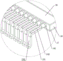
Fig. 18 is a schematic view of the connection of a coaxial cable to a male terminal.
Fig. 19 is an enlarged view of a portion C in fig. 18.
Detailed Description
The following detailed description is to be read in connection with the drawings and the preferred embodiments.
An embodiment of a high-speed micro coaxial connector assembly, as shown in fig. 1 to 19, includes a male terminal connector 1 and a female terminal connector 2 that are adapted to be plugged, where the male terminal connector 1 includes a male terminal shielding shell 11, a male terminal insulator 12 disposed in the male terminal shielding shell 11, male terminals 13 disposed in the male terminal insulator 12 in a row, and coaxial cables 14 connected to the male terminals 13 in a one-to-one correspondence; the diameter of the coaxial cable is 0.30mm, but the invention is not limited to this, and the diameter of the coaxial cable can be adaptively adjusted according to actual needs. Female end connector 2 includes female end insulator 21, female end shielding shell 22 and sets up in female end terminal 23 in female end insulator in a row, female end shielding shell 22 is installed on female end insulator 21, and female end connector 2 is installed on the PCB board, sets up the pad on the PCB board, and the pad corresponds with female end terminal to be connected.
In this embodiment, the female terminal 23 is integrally injection-molded with the female insulator 21 in an Insert Molding (Insert Molding) manner, so that the female terminal 23 can be orderly arranged in the female insulator 21, the coplanarity of all the terminals is extremely high, dense arrangement of the terminals is facilitated, and the high-speed transmission performance of the connector can be improved under the condition of effectively reducing the overall size of the connector. Referring to fig. 12, the female terminal 23 includes a soldering terminal 231, a fixing portion 232, and a contact terminal 233 connected in sequence; the welding end is horizontally extended and arranged and is used for being electrically connected with a welding pad on the PCB, the fixing part is U-shaped, the fixing part is integrally embedded in the female end insulator, the direction shown in the figure 10 is taken as a reference, and the fixing part of the U-shaped structure enables the female end terminal to form a stable limit matching relation with the female end insulator in the up-down direction, the left-right direction and the left-right direction, so that the stability of the female end terminal is ensured, and the problem of terminal looseness in a frequent plugging scene is avoided; in other embodiments, the fixing portion may have an S-shape or a continuous S-shape. The fixed part 232 is connected to the one end of contact end 233, and the other end is the free end to make the contact end form shell fragment structure, possess the elastic contact ability, contact end 233 wholly hangs and sets up in the terminal jack 3 that opens and establish in female end insulator 21. Preferably, the contact end 233 is S-shaped with a spring contact 234 in contact with the male terminal.
The female-end shielding shell 22 is fixedly assembled on the female-end insulator 21 in a forced assembly manner, as shown in fig. 8 and 11, the female-end shielding shell is of a rectangular frame structure, the left side and the right side of the female-end shielding shell 22 are provided with fixing plates 221 extending along the plugging and unplugging direction of the connector, barbs 2211 are symmetrically arranged on two sides of each fixing plate, and the barbs are in interference fit with the hole walls of the fixing holes 215 preset on the female-end insulator so as to realize the positioning of the female-end shielding shell; furthermore, the female end shielding shell is provided with a convex shoulder 2212 positioned above the barb, and the convex shoulder and the female end insulator are in stop fit in the forced installation direction, so that the mounting and limiting of the female end shielding shell are realized. Female end shielding shell is rectangle frame rack construction, as shown in fig. 8, both sides have the shielding curb plate 222 that extends to the downward bending (extend towards the PCB board direction) around female end shielding shell 22, and two relative distribution's shielding curb plate are connected between the fixed part of the left and right sides, and shielding curb plate bottom has a plurality of shielding pins 223 that distribute the setting, shielding pin be used for with the ground connection hole or the ground connection pad welding on the PCB board. In order to further improve the installation stability of the female-end shielding shell, the left side and the right side of the female-end shielding shell 22 are provided with inserting pieces 224, correspondingly, slots 211 are formed in the female-end insulator 21, interference convex points matched with the inner walls of the slots are arranged on two sides of the inserting pieces, and the inserting pieces are in forced fit with the slots to achieve auxiliary positioning of the female-end shielding shell.
Female end insulator 21 is last to set up interval rib 4 along length direction extension, and one side of interval rib 4 is above-mentioned terminal jack 3, and the opposite side is shielding jack 5, and interval rib 4 separates terminal jack 3 and shielding jack 5 to the terminal that will be responsible for transmitting coaxial signal and the structure of being responsible for shielding ground connection keep apart each other, avoid the mistake to touch. One side of female end shielding shell 22 extends towards in shielding jack 5 and forms interior curb plate 225, be equipped with a plurality of female end shielding elastic claw 226 on the interior curb plate 225, constitute the centre gripping chamber between the shielding curb plate of interior curb plate and its place side, the mutual grafting cooperation of edge rib 2120 of centre gripping chamber and shielding jack 5 one side, set up on the edge rib and shield the corresponding hole 212 of dodging of elastic claw position with female end, dodge hole 212 and be used for holding female end shielding elastic claw 226 when female end shielding elastic claw is pegged graft with public end shielding elastic claw.
The both sides of public end insulator 12 are equipped with hasp 6 respectively, and corresponding sets up the locked groove 7 with hasp 6 one-to-one snap-fit in the both sides of female end shielding shell 22, and open the both sides of female end insulator 21 in addition is equipped with hasp and keeps away hole 210, and the hasp keeps away the hole and lies in one side of the locked groove of homonymy to supply when inserting to close locking the hasp gets into the hasp and keeps away the hole. Referring to fig. 5, the latch 6 includes a movable portion 61 and a fixed portion 62 connected to each other, one end of the movable portion 61 is connected to the fixed portion 62 to make the latch have a U-shaped plate structure, that is, the movable portion and the fixed portion are parallel to each other, and the connecting portion of the movable portion and the fixed portion is a bending section; the male end insulator 12 is provided with a mounting groove 121 for mounting the lock catch, two sides of the fixing part 62 are oppositely provided with interference protrusions 621, and the interference protrusions 621 are in interference fit with the inner wall 1211 of the mounting groove 121 to realize the fixed assembly of the lock catch; the outer wall of the movable part 61 is convexly provided with a locking part 63, and the locking part is used for being matched with the locking groove in a blocking mode in the direction deviating from the insertion direction, so that male and female locking limiting is achieved. The other end of the movable part 61 is provided with an unlocking part 64, the unlocking part 64 is formed by bending and extending the top end of the movable part obliquely outwards and then bending and extending upwards, so that the distance between the unlocking part and the fixed part is greater than the distance between the movable part and the fixed part, and the force application unlocking is facilitated. When unlocking, the unlocking part 64 is pressed to drive the movable part to elastically deform inwards, so that the locking part 63 is separated from the locking groove 7, and unlocking is realized. Preferably, the lower end of the locking part is provided with a guide inclined surface 631, so that when the male end connector is inserted, the movable part is compressed inwards under the acting force of the female end shielding shell, and after the movable part reaches the locking position, the movable part is elastically deformed and enters the locking groove; the upper end of the unlocking part is a plane 632 to avoid mistaken unlocking. Further, two sides of the fixing portion 62 are symmetrically provided with a retaining shoulder 622, and the retaining shoulders are located above the interference protrusion 621 on the corresponding side; the mounting groove 121 is provided with steps 1212 corresponding to the shoulders one by one, and when the lock catch is mounted, the shoulders and the steps are matched in a blocking manner in the lock catch mounting direction, so that the mounting and limiting of the lock catch 6 are realized.
Preferably, a positioning pin 213 is convexly disposed on a surface of the female terminal insulator 21 facing the PCB, and the positioning pin 213 is engaged with a positioning hole preset on the PCB to achieve guiding and positioning of the female terminal connector. Female end insulator 21 still sets up a plurality of auxiliary positioning key 214 along the ascending front and back side of length direction, sets up auxiliary positioning groove 227 on the shielding curb plate of female end shielding shell 22, realizes the guide assembly and the assembly spacing of female end shielding shell through the keyway cooperation.
In this embodiment, the male terminal 13 is preferably formed integrally with the male insulator 12 by insert molding, so as to ensure stability and coplanarity of the male terminal in the case of high-density terminal deployment. Referring to fig. 14, the male shielding shell 11 is a flattened rectangular conductive shell, and the male insulator is inserted into the male shielding shell for fixation, and the two are either interference fit or connected and positioned by a snap structure. Coaxial cable 14 is arranged in one row, and all coaxial cable 14 all wear to adorn in afterbody insulating sleeve 15, and afterbody insulating sleeve 15 is fixed in the rear end of public end insulator 12, not only realizes that public end connector afterbody is sealed, can also provide certain tensile ability for coaxial cable 14. After the connecting end of the coaxial cable 14 is penetrated through the tail insulator, the coaxial cable is peeled off to expose the shielding layer 141 inside the coaxial cable, and then the shielding layer 141 is soldered between the upper conductive strip 16 and the lower conductive strip 17. As shown in fig. 19, soldering tin is disposed on the opposite surfaces of the upper and lower conductive strips, and then a row of shielding layers are soldered and fixed in the soldering tin layer 18 between the two conductive strips after heating, so that the shielding layers of all coaxial cables are electrically connected to each other. Further, the connection end of the coaxial cable has a core 142 stripped off, and the core 142 is soldered to the upper surface of the terminal 131 of the male terminal 13. The male terminal is of an L-shaped sheet structure and comprises a wiring terminal 131 and an inserting terminal 132 which are perpendicular to each other, the wiring terminal and the inserting terminal are bent and transited, the inserting terminal and the wiring terminal are fixedly embedded in the male terminal insulator, and the inserting terminal 132 is used for being in contact with a contact end 233 of the female terminal after the male connector and the female connector are inserted.
The lower extreme of public end insulator 12 is equipped with shielding piece 19, and shielding piece 19 both sides are equipped with jack catch 191, offer on the public end insulator 12 with jack catch interference fit's jack catch groove 122, shielding piece 19 fixes in public end insulator 12 below with the help of the jack catch mode of forced fit. The shielding plate 19 is provided with a plurality of first conductive elastic pieces 192 protruding toward the lower conductive strip 17, and after the shielding plate 19 is installed in place, the first conductive elastic pieces 192 elastically contact the lower conductive strip 17, so as to realize shielding conduction between the shielding plate and the lower conductive strip. One end of the shielding plate 19 is provided with a plurality of male shielding elastic claws 193, the male shielding elastic claws 193 are distributed along the length direction of the shielding plate, the male shielding elastic claws are formed by bending one end of the shielding plate downwards and extending and then bending the end of the shielding plate upwards to form U-shaped male shielding elastic claws, and the male shielding elastic claws 193 are used for being in elastic contact conduction with the female shielding elastic claws 226. As shown in fig. 17, two rows of distributed contacts are disposed on the male end connector, one row is a male end terminal, the other row is a male end shielding spring claw, and the two rows of contacts form two rows of plug structures, which correspond to the terminal jacks and the shielding jacks in the female end connector one to one.
Preferably, in order to protect the welding point position where the male terminal is welded with the core of the coaxial cable, an insulating protection plate 110 is fixedly arranged in the male terminal insulator, and the insulating protection plate 110 covers the upper part of the terminal. As a further improvement, one side of the insulating protective plate 110 facing the wiring end is provided with a row of wire core grooves, and each wire core groove is internally provided with a wire core of a coaxial cable. In this embodiment, the insulating protection plate 110 is made of UV glue, and is fixed to the male end insulator by adhesion. In addition, the tail insulating sleeve 15 is formed after the UV glue is cured. In addition, the male-end shielding shell is convexly provided with a plurality of second conductive elastic sheets 111 towards the direction of the upper conductive strip, and the second conductive elastic sheets are elastically contacted with the upper conductive strip 16 to realize the shielding conduction between the male-end shielding shell and the shielding layer of the coaxial cable; furthermore, the contact position of the second conductive elastic sheet and the upper conductive strip is welded, so that the contact stability of the male-end shielding shell and the upper conductive strip can be improved, and the positioning of the male-end shielding shell is facilitated; similarly, the first conductive elastic sheet can be soldered by tin penetration.
As shown in fig. 10, preferably, the top end of the spacing rib 4 is provided with a limiting platform 41 protruding towards the contact end 233 direction of the female terminal, the limiting platform 41 is provided with a row of guiding through grooves 42 along the length direction thereof, as shown in fig. 9, the number of the guiding through grooves is consistent with the number of the female terminal, and the contact end of the female terminal is located under the corresponding guiding through groove, in the inserting and combining process of the male and female connectors, the male terminal firstly passes through the guiding through groove and then elastically contacts with the corresponding female terminal, and the guiding through groove plays a role in guiding and inserting and combining the male terminal. In addition, the setting height of spacing platform is higher than female end shielding shell, inserts to close when locking with public end insulator butt and also can realize the spacing effect of inserting of public end connector.
After the male end connector is inserted into the female end connector, the male end terminal and the female end terminal are in mutual elastic contact in the terminal jack, and transmission of coaxial signals is achieved; public end shielding elastic claw and female end shielding elastic claw each other elastic contact in the shielding jack realizes the shielding ground connection of public female bi-polar and switches on, and public end shielding shell and female end shielding shell each other contact have further promoted the shielding effect of high-speed superfine coaxial connector subassembly simultaneously for transmission signal's in-process forms three-dimensional full enclosure shield in the circumference of public, female terminal cooperation district, has ensured the high speed performance of connector subassembly.
In other embodiments, two or more rows of male terminal terminals may be arranged at intervals in the male terminal connector along the front-back direction, at this time, coaxial cables of corresponding rows are arranged, the coaxial cables of adjacent rows are stacked up and down, and each row of coaxial cables are arranged in parallel along the width direction from the tail of the male terminal connector; to achieve common grounding of the rows of male terminals, the conductive bars belonging to adjacent rows may be connected by welding or by contact overlap.
The specific structure of the embodiment of the male end connector in the present invention, that is, the male end connector described in the above-mentioned high-speed ultrafine coaxial connector assembly, is not described herein again.
The above description is only a preferred embodiment of the present invention, and any person skilled in the art can make any simple modification, equivalent change and modification to the above embodiments according to the technical essence of the present invention without departing from the scope of the present invention, and still fall within the scope of the present invention.