CN113376401A - Flow-controllable tracer molecule adding device and adding method thereof - Google Patents
Flow-controllable tracer molecule adding device and adding method thereof Download PDFInfo
- Publication number
- CN113376401A CN113376401A CN202110464867.2A CN202110464867A CN113376401A CN 113376401 A CN113376401 A CN 113376401A CN 202110464867 A CN202110464867 A CN 202110464867A CN 113376401 A CN113376401 A CN 113376401A
- Authority
- CN
- China
- Prior art keywords
- liquid
- gas
- mixing chamber
- pressure
- flow
- Prior art date
- Legal status (The legal status is an assumption and is not a legal conclusion. Google has not performed a legal analysis and makes no representation as to the accuracy of the status listed.)
- Granted
Links
Images


Classifications
-
- G—PHYSICS
- G01—MEASURING; TESTING
- G01P—MEASURING LINEAR OR ANGULAR SPEED, ACCELERATION, DECELERATION, OR SHOCK; INDICATING PRESENCE, ABSENCE, OR DIRECTION, OF MOVEMENT
- G01P5/00—Measuring speed of fluids, e.g. of air stream; Measuring speed of bodies relative to fluids, e.g. of ship, of aircraft
- G01P5/18—Measuring speed of fluids, e.g. of air stream; Measuring speed of bodies relative to fluids, e.g. of ship, of aircraft by measuring the time taken to traverse a fixed distance
- G01P5/20—Measuring speed of fluids, e.g. of air stream; Measuring speed of bodies relative to fluids, e.g. of ship, of aircraft by measuring the time taken to traverse a fixed distance using particles entrained by a fluid stream
-
- B—PERFORMING OPERATIONS; TRANSPORTING
- B01—PHYSICAL OR CHEMICAL PROCESSES OR APPARATUS IN GENERAL
- B01D—SEPARATION
- B01D46/00—Filters or filtering processes specially modified for separating dispersed particles from gases or vapours
- B01D46/10—Particle separators, e.g. dust precipitators, using filter plates, sheets or pads having plane surfaces
-
- B—PERFORMING OPERATIONS; TRANSPORTING
- B01—PHYSICAL OR CHEMICAL PROCESSES OR APPARATUS IN GENERAL
- B01L—CHEMICAL OR PHYSICAL LABORATORY APPARATUS FOR GENERAL USE
- B01L7/00—Heating or cooling apparatus; Heat insulating devices
Landscapes
- Chemical & Material Sciences (AREA)
- Chemical Kinetics & Catalysis (AREA)
- Health & Medical Sciences (AREA)
- Clinical Laboratory Science (AREA)
- Engineering & Computer Science (AREA)
- Aviation & Aerospace Engineering (AREA)
- Physics & Mathematics (AREA)
- General Physics & Mathematics (AREA)
- Indicating Or Recording The Presence, Absence, Or Direction Of Movement (AREA)
- Organic Low-Molecular-Weight Compounds And Preparation Thereof (AREA)
Abstract
The invention discloses a flow-controllable tracer molecule adding device and a flow-controllable tracer molecule adding method, and belongs to the field of molecular marker flow fields. According to the tracer molecule adding device, the tracer molecules are added into the main flow field by utilizing the bypass gas, and the gas-liquid contact area can be increased by the metal corrugated plate in the mixing chamber, so that the partial pressure of the tracer molecules in the gas flow can reach the saturated vapor pressure of the tracer molecules; heating devices are arranged in the heating chamber and the mixing chamber, the heating devices can heat the missing molecular liquid, and the arranged temperature sensor and the pressure sensor can acquire corresponding data to provide data for accurate control of the realized quantity; and finally, adding the tracer molecules into the main stream by using the high-pressure blowing spray pipe, and fully mixing the tracer molecules with the main stream. The tracer molecule adding device has the advantages of simple structure, convenience in processing, small device volume, convenience in carrying, suitability for adding tracer molecules in flow fields of various complex equipment and strong adaptability.
Description
Technical Field
The invention belongs to the technical field of molecular marker speed measurement, and particularly relates to a flow-controllable tracer molecule adding device and a flow-controllable tracer molecule adding method.
Background
In the field of modern aerospace, high-precision measurement of flow velocity has great significance for design and theoretical research of engines. The high-precision and reliable flow field parameter measurement technology plays a key role in the research of combustion basic problems, the analysis of flow field characteristics and the research and development of engines, can provide experimental data for the research of fluid dynamics, combustion chemical reaction dynamics and numerical simulation calculation, and is also an indispensable means for the parameter test of engine models and the performance evaluation of engines. In recent years, with the rapid development of laser technology, spectrum and image acquisition technology, molecular marker speed measurement technology has been developed well. By adding the tracer molecules into the main flow field, the tracer molecules are excited by laser with specific wavelength to generate fluorescence or phosphorescence to mark and trace the flow field, and then the flow field speed is obtained based on the displacement-time relation of the tracer molecules. Wherein, the reasonable addition of the tracer molecules in the main flow field plays a key role in the measurement of the velocity field.
For the addition of the tracer molecule reagent, a common method is to utilize a bypass auxiliary airflow to carry the tracer molecules into a flow field to be measured, and for the tracer molecule reagent which is liquid at normal temperature, the requirement of measuring the speed of a main flow field cannot be met only by the volatility of the tracer molecules, in addition, when the bypass is not arranged properly, the tracer molecules can be caused to enter the flow field to be measured in a liquid drop mode, so that the accurate measurement of the speed field in the main flow field is influenced, meanwhile, a large amount of waste of the tracer molecules can be caused, and the problem that the wide application of the tracer molecule speed measuring technology is limited at present is also one of the problems. Therefore, an appropriate adding device for the tracer molecules is urgently needed, and accurate adding and control of the tracer molecules in the main flow field can be realized.
Disclosure of Invention
The invention aims to overcome the defect that the amount of tracer molecules added into a flow field to be detected is uncontrollable, and provides a flow-controllable tracer molecule adding device and a flow-controllable tracer molecule adding method.
In order to achieve the purpose, the invention adopts the following technical scheme to realize the purpose:
a flow-controllable tracer molecule adding device comprises a heating chamber, a liquid removing chamber and a mixing chamber;
a liquid filling opening is formed in the heating chamber, a first temperature sensor is arranged in the heating chamber, the heating chamber is communicated with the mixing chamber through a liquid conveying pipe, and an automatic liquid level control switch is arranged on the liquid conveying pipe;
an air inlet pipe is arranged on the mixing chamber, and an automatic air inlet control switch is arranged on the air inlet pipe;
the lower part of the mixing chamber is provided with a gas distributor, and the gas distributor is provided with a plurality of metal corrugated plates;
the gas distributor is also provided with a baffle, the baffle is attached to the inner wall of the mixing chamber, a second pressure sensor is arranged in the baffle and the inner wall of the mixing chamber, and a first pressure sensor is arranged at the upper part of the mixing chamber;
the inner wall of the mixing chamber is provided with a heating resistance wire, and the top of the mixing chamber is communicated with the liquid removing chamber through a communicating pipe;
the inside of the liquid removing chamber is provided with a wire mesh filter, the top of the liquid removing chamber is provided with an exhaust pipe, and the tail end of the exhaust pipe is provided with a high-pressure blowing nozzle.
Further, the heating chamber is communicated with the liquid removing chamber through a vent pipe.
Further, a second temperature sensor is arranged on the inner wall of the mixing chamber below the gas distributor;
the bottom of the mixing chamber is provided with a liquid outlet.
Further, the air inlet pipe is a bent pipe.
A flow-controllable tracer molecule adding method is carried out based on the flow-controllable tracer molecule adding device, and negative feedback adjustment is carried out by using an automatic air inlet control switch, so that the outlet flow of a high-pressure air blowing nozzle is controlled;
the temperature is controlled through negative feedback regulation, so that the mole fraction of the tracer molecules in the airflow at the outlet of the high-pressure blowing nozzle is controlled;
the liquid level height is controlled between the preset ranges by negative feedback regulation by using the liquid level automatic control switch.
Further, an automatic air inlet control switch is used for negative feedback adjustment, so that the process of controlling the flow of the outlet of the high-pressure air blowing nozzle is as follows:
establishing a mathematical relationship between the high pressure blowing nozzle outlet flow and the gas pressure inside the mixing chamber based on fluid dynamics;
acquiring the gas pressure of the mixing chamber measured by the first pressure sensor, and acquiring the corresponding outlet flow of the high-pressure blowing nozzle;
and the automatic air inlet control switch is used for negative feedback adjustment to control the air pressure of the mixing chamber, so that the control of the outlet flow of the high-pressure air blowing nozzle is realized.
Further, the temperature control is realized by negative feedback regulation, so that the process of controlling the mole fraction of the tracer molecules in the outlet gas flow comprises the following steps:
calculating the partial pressure p of the tracer molecule according to the gas pressure in the mixing chamber and the mole fraction of the tracer moleculev;
Heating the tracer molecule liquid to a saturation temperature at said partial pressure to bring the tracer molecule gas pressure in the mixing chamber to said partial pressure;
acquiring the gas pressure of a mixing chamber measured by a first pressure sensor, and comparing the partial pressure with the gas pressure of the mixing chamber to obtain the mole fraction of the tracer molecules in the mixed gas;
temperature control is achieved through negative feedback regulation, and therefore the mole fraction of the tracer molecules in the outlet gas stream is controlled.
Further, the process of controlling the liquid level height between the preset ranges by utilizing the liquid level automatic control switch through negative feedback adjustment comprises the following steps:
acquiring data measured by a first pressure sensor and a second pressure sensor, wherein the first pressure sensor measures the gas pressure in the mixing chamber, and the second pressure sensor measures the liquid pressure;
calculating the liquid level height in the mixing chamber based on the pressure difference between the first pressure sensor and the second pressure sensor;
the liquid level height is controlled between the preset ranges by negative feedback regulation by using the liquid level automatic control switch.
Further, the method comprises the following operations:
adding the tracer molecule liquid into the heating chamber through a liquid filling port, heating the tracer molecule liquid to the saturation temperature by the heating plate, and allowing the tracer molecule liquid to flow into the mixing chamber through the automatic liquid level control switch and the liquid conveying pipe;
the tracer molecule liquid in the heating resistance wire in the mixing chamber is reheated;
the bypass gas respectively enters the mixing chamber through the gas inlet pipe and the automatic gas inlet control switch, the entering gas forms initial distribution of the gas through the gas distributor, and then the gas flows upwards and flows through the metal corrugated plate;
evaporating the heated liquid portion of the tracer molecule, the evaporated tracer molecule gas contacting and mixing with the flowing gas;
the mixed gas in the mixing chamber enters the liquid removing chamber through the communicating pipe, when the mixed gas enters the liquid removing chamber, the cross section of the airflow is suddenly increased, and the liquid in the airflow falls off from the airflow under the action of self gravity, falls into the liquid removing chamber and then flows back to the mixing chamber through the communicating pipe;
the mixed gas in the liquid removing chamber flows through a wire mesh filter to remove fine liquid drops, and a heating resistance wire on the wire mesh filter reheats the mixed gas;
the reheated mixed gas flows out of the liquid removing chamber through the exhaust pipe and enters the high-pressure blowing nozzle, and the mixed gas containing the tracer molecule gas is sprayed into the main flow field through the high-pressure blowing nozzle.
Compared with the prior art, the invention has the following beneficial effects:
according to the flow-controllable tracer molecule adding device, the tracer molecules are added into the main flow field by utilizing the bypass gas, the contact area of gas and liquid can be increased by the metal corrugated plate in the mixing chamber, the mass transfer and heat transfer between the gas and the liquid are enhanced, and the partial pressure of the tracer molecules in the gas flow can reach the saturated vapor pressure; heating devices are arranged in the heating chamber and the mixing chamber, the heating devices can heat the missing molecular liquid, and the arranged temperature sensor and the pressure sensor can acquire corresponding data to provide data for accurate control of the realized quantity; and finally, the tracer molecules are added into the main stream by using the high-pressure blowing spray pipe, so that the tracer molecules and the main stream can be fully mixed, the initial distribution of the tracer molecules in a main stream field is enhanced, and the flow characteristics of the flow field can be further detected by a molecular marker testing technology. The tracer molecule adding device has the advantages of simple structure, convenience in processing, small device volume, convenience in carrying, suitability for adding tracer molecules in flow fields of various complex equipment and strong adaptability.
Further, the heating chamber is communicated with the liquid removing chamber through the vent pipe, the liquid removing chamber is communicated with the mixing chamber through the communicating pipe, the pressure inside the liquid removing chamber and the pressure inside the mixing chamber are equal, and the situation that liquid in the heating chamber cannot flow into the mixing chamber when the pressure in the mixing chamber is higher than the pressure in the heating chamber is avoided.
Further, the return bend is set to the intake pipe, can effectively prevent that device from taking place the backward flow in start-up stage or stop stage mixing chamber liquid to avoid the waste of tracer molecule.
Further, the existence of the liquid removing chamber can remove small liquid drops existing in the air flow, and the efficiency of the blowing nozzle is improved.
The flow-controllable tracer molecule adding method disclosed by the invention is based on the fluid dynamics principle and the thermophysical properties of the tracer molecules, and realizes the mole fraction control, the flow control and the liquid level control of the tracer molecules. On one hand, the mole fraction of the tracer molecules in the outlet gas flow can be accurately controlled, so that the precise addition of the tracer molecules in the main flow field is realized; on the other hand, the device can be prevented from running in the air due to the depletion of the tracer molecules, the reliability of the device is ensured, and the problems of tracer molecule addition in a complex flow field and the like are solved.
Drawings
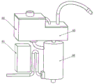
FIG. 1 is a block diagram of the present invention;
FIG. 2 is a cross-sectional view of the present invention;
FIG. 3 is a block diagram of a gas distributor of the present invention;
fig. 4 is a structural view of a corrugated metal plate, in which fig. 4(a) is a flat plate structure and fig. 4(b) is a structure punched out into a spiral;
fig. 5 is a schematic view of a metal corrugated plate in a hybrid loading mode.
Wherein: 01-a control room; 02-a heating chamber; 03-a deliquoring chamber; 04-a mixing chamber; 1, an air inlet pipe; 2-a transfusion tube; 3-automatic liquid level control switch; 4-heating the plate; 5-a first temperature sensor; 6-a liquid adding port; 7-a breather pipe; 8-high pressure blowing nozzle; 9-an exhaust pipe; 10-wire mesh filter; 11-communicating tube; 12-a first pressure sensor; 13-a baffle; 14-heating resistance wires; 15-a second pressure sensor; 16-a second temperature sensor; 17-a gas distributor; 18-a liquid drain port; 19-corrugated metal plate; 20-automatic air inlet control switch.
Detailed Description
In order to make the technical solutions of the present invention better understood, the technical solutions in the embodiments of the present invention will be clearly and completely described below with reference to the drawings in the embodiments of the present invention, and it is obvious that the described embodiments are only a part of the embodiments of the present invention, and not all of the embodiments. All other embodiments, which can be derived by a person skilled in the art from the embodiments given herein without making any creative effort, shall fall within the protection scope of the present invention.
It should be noted that the terms "first," "second," and the like in the description and claims of the present invention and in the drawings described above are used for distinguishing between similar elements and not necessarily for describing a particular sequential or chronological order. It is to be understood that the data so used is interchangeable under appropriate circumstances such that the embodiments of the invention described herein are capable of operation in sequences other than those illustrated or described herein. Furthermore, the terms "comprises," "comprising," and "having," and any variations thereof, are intended to cover a non-exclusive inclusion, such that a process, method, system, article, or apparatus that comprises a list of steps or elements is not necessarily limited to those steps or elements expressly listed, but may include other steps or elements not expressly listed or inherent to such process, method, article, or apparatus.
The invention is described in further detail below with reference to the accompanying drawings:
referring to fig. 1 and 2, fig. 1 and 2 are a structural view and a sectional view, respectively, of a flow-controllable tracer molecule adding device of the present invention, which includes a control chamber 01, a heating chamber 02, a liquid removing chamber 03, and a mixing chamber 04; the control chamber 01 is used for controlling the flow of the whole device, the heating temperature of the tracer molecules and the liquid level of the mixing chamber according to the data of the first pressure sensor 4, the second pressure sensor 13, the first temperature sensor 10 and the second temperature sensor 14; the heating plate 3 is arranged at the bottom of the heating chamber 02, and can be used for preliminarily heating the tracer molecule liquid to reach the saturation temperature; the mixing chamber 04 can fully mix gas and liquid, enhance mass and heat transfer between gas and liquid, and the inner wall surface of the mixing chamber is provided with an electric heating resistance wire with the diameter of 0.25mm, so that liquid can be reheated, and the temperature of the liquid is ensured to reach the saturation temperature; the metal wire mesh filter 9 is used in the liquid removing chamber 03 to further remove small liquid drops in the air flow, so that the high-efficiency work of the high-pressure blowing nozzle is guaranteed, and the accurate addition of the tracer molecules in the main flow field is realized. Wherein, the heating chamber 02 is box-shaped, and the size is 120mm multiplied by 100 mm; the mixing chamber 04 is hollow cylindrical, the diameter is 80mm, and the height is 150 mm; the liquid removing chamber 03 is box-shaped, and the size is 100mm multiplied by 120mm multiplied by 55 mm; .
Control system design
1) Flow control
According to the designed high-pressure stainless steel blowing nozzle 8 and the characteristics of the inner flow channel, the relation between the outlet flow and the pressure in the mixing chamber is established on the basis of fluid dynamics, and according to the numerical value of the first pressure sensor 12, the automatic air inlet control switch 20 is utilized to determine the mixed internal pressure through negative feedback adjustment, so that the outlet flow is accurately controlled.
2) Temperature control
Calculating the partial pressure p of the tracer molecule from the pressure inside the mixing chamber and the mole fraction of the tracer moleculev(pv=px,pvIs the partial pressure of the tracer molecule, p is the total pressure of the mixing chamber and x is the mole fraction of tracer molecule in the outlet gas stream). According to the thermophysical property of the tracer molecules, the heating plate 4 in the mixing chamber and the heating resistance wire 14 of the heating chamber are utilized to heat the tracer molecule liquid to the saturation temperature under the partial pressure, and the accurate control of the temperature is realized through negative feedback regulation, so that the molar quantity of the tracer molecules in the outlet airflow is ensuredAnd (4) scoring.
3) Liquid level control
In order to ensure the mixing degree of gas and liquid in the mixing chamber, the liquid level needs to be kept to a certain height, and a liquid level control system is designed. The baffle 13 is designed in the mixing chamber, and simultaneously, due to the action of the gas distributor 17, no gas flows in the baffle 13, and the measurement of the pressure of the second sensor 15 is not influenced; secondly, monitoring the liquid level height (Δ p ═ ρ gh) in the mixing chamber in real time according to the pressure difference between the first pressure sensor 12 and the second pressure sensor 15; finally, the liquid level height is controlled to be between 100mm and 120mm through negative feedback adjustment by using the liquid level automatic control switch 3, if the liquid level height is lower than 100mm, the switch is turned on to supplement the liquid level height to 120mm, and then is turned off until tracer molecules in the heating chamber are exhausted; when the liquid level is lower than 60mm, the tracer liquid is exhausted, and the equipment stops working. Meanwhile, in order to ensure that the liquid in the heating chamber can be added into the mixing chamber under the action of self gravity, the vent pipe 7 is adopted to indirectly communicate the liquid.
Structural design
1) Gas distributor
The primary purpose of the gas distributor 15 is to redistribute the gas entering the mixing chamber so that the gas and liquid are mixed more evenly in the mixing chamber and also to provide a support for the corrugated metal plate 19. The gas distributor 15 is regularly opened with the through-hole that the diameter is 3mm on a metal sheet that thickness is 2mm, in order to guarantee that gas does not get into in the middle of baffle 17, avoids influencing the measurement of pressure simultaneously, does not open the through-hole in support baffle department. Referring to fig. 3, fig. 3 is a structural diagram of the gas distributor, it can be seen that a plurality of gas holes are distributed on a disk-shaped base body, and a part of the periphery of the base body is not provided with the gas holes, and is used for installing a baffle 13.
2) Structure of corrugated metal plate
In order to enhance the mass and heat transfer process between gas and liquid, a metal corrugated plate 19 is designed according to the flow characteristic of the gas and liquid in the mixing chamber between two phases, so that the contact area between the gas and the liquid is increased. Referring to fig. 4, fig. 4 is a flat plate structure, and fig. 4 is a structure punched into a spiral.
The metal corrugated plates are regularly filled in the gas distributor 15 according to the mode of figure 5, and in figure 5, the metal corrugated plates 19 can be arranged on the air holes of the gas distributor 15, so that the contact area between gas and liquid phases can be increased to a great extent.
3) Wire mesh filter 10 structural design
The use method of the flow-controllable tracer molecule adding device comprises the following specific steps:
adding tracer molecule liquid (such as diacetyl and acetone) into a heating chamber 01 through a liquid adding port 6, heating the tracer molecule liquid to the saturation temperature by a heating plate 4 of the heating chamber 01, and allowing the tracer molecule liquid to flow into a mixing chamber 04 through an automatic liquid level control switch 3 and a liquid conveying pipe 2; a heating resistance wire 14 in the mixing chamber 04 reheats the entering tracer molecule liquid;
the heating chamber 02 is communicated with the liquid removing chamber 03 through the vent pipe 7, and the liquid removing chamber 03 is communicated with the mixing chamber 04 through the communicating pipe 11, so that the heating chamber 02 and the mixing chamber 04 are communicated, the pressure inside the heating chamber 02 and the mixing chamber 04 is ensured to be equal, and the situation that liquid in the heating chamber 02 cannot flow into the mixing chamber 04 when the pressure in the mixing chamber 04 is higher than that of the heating chamber 02 is avoided;
meanwhile, bypass gas respectively enters the mixing chamber 04 through the gas inlet pipe 1 and the automatic gas inlet control switch 20, the entering gas forms initial distribution of the gas after passing through the gas distributor 17 at the bottom of the mixing chamber 04, then the gas flows upwards and flows through the corrugated metal plate 19, the flowing gas is fully contacted with the tracer molecule liquid, a part of tracer molecule solution is subjected to phase change and is fully mixed with the gas, and the concentration of the tracer molecule solution can reach the saturated vapor pressure of the tracer molecule;
the gas in the mixing chamber 04 enters the liquid removing chamber 03 through the communicating pipe 11, when the gas enters the liquid removing chamber 03, the cross section of the gas flow is suddenly increased, the liquid in the gas flow falls off from the gas flow under the action of the gravity of the liquid in the gas flow, falls into the liquid removing chamber 03 and then flows back to the mixing chamber 04 through the communicating pipe 11;
the gas in the liquid removal chamber 03 flows through the wire mesh filter 10 to remove fine liquid drops contained in the gas flow, and the heating resistance wire on the wire mesh filter 10 reheats the gas to prevent the tracer molecule gas in the gas from condensing;
the reheated tracer molecule gas flows out of the liquid removing chamber 03 through the exhaust pipe 9 and enters the blowing nozzle 8 made of high-pressure stainless steel, and the blowing nozzle 8 sprays the gas flow containing the tracer molecule gas into the main flow field to realize the accurate addition of the tracer molecules;
after the experiment is finished, the liquid outlet 18 is adopted to recycle the solution, so that the cyclic utilization of the tracer molecule liquid is realized.
The above-mentioned contents are only for illustrating the technical idea of the present invention, and the protection scope of the present invention is not limited thereby, and any modification made on the basis of the technical idea of the present invention falls within the protection scope of the claims of the present invention.
Claims (9)
1. A flow-controllable tracer molecule adding device is characterized by comprising a heating chamber (02), a liquid removing chamber (03) and a mixing chamber (04);
a liquid filling opening (6) is formed in the heating chamber (02), a first temperature sensor (5) is arranged in the heating chamber (02), the heating chamber (02) is communicated with the mixing chamber (04) through a liquid conveying pipe (2), and an automatic liquid level control switch (3) is arranged on the liquid conveying pipe (2);
an air inlet pipe (1) is arranged on the mixing chamber (04), and an automatic air inlet control switch (20) is arranged on the air inlet pipe (1);
a gas distributor (17) is arranged at the lower part of the mixing chamber (04), and a plurality of metal corrugated plates (19) are arranged on the gas distributor (17);
a baffle (13) is further arranged on the gas distributor (17), the baffle (13) is attached to the inner wall of the mixing chamber (04), a second pressure sensor (15) is arranged in the baffle (13) and the inner wall of the mixing chamber (04), and a first pressure sensor (12) is arranged at the upper part of the mixing chamber (04);
a heating resistance wire (14) is arranged on the inner wall of the mixing chamber (04), and the top of the mixing chamber (04) is communicated with the liquid removing chamber (03) through a communicating pipe (11);
a wire mesh filter (10) is arranged in the liquid removing chamber (03), an exhaust pipe (9) is arranged at the top of the liquid removing chamber (03), and a high-pressure blowing nozzle (8) is arranged at the tail end of the exhaust pipe (9).
2. The flow-controllable tracer molecule adding device according to claim 1, wherein the heating chamber (02) is communicated with the liquid removing chamber (03) through a vent pipe (7).
3. The flow-controllable tracer molecule adding device according to claim 1, wherein a second temperature sensor (16) is disposed on an inner wall of the mixing chamber (04) below the gas distributor (17);
the bottom of the mixing chamber (04) is provided with a liquid outlet (18).
4. Flow-controllable tracer molecule addition device according to claim 1, wherein the inlet pipe (1) is a bent pipe.
5. A flow-controllable tracer molecule adding method is characterized in that the flow-controllable tracer molecule adding method is carried out based on the flow-controllable tracer molecule adding device of claim 1, 2, 3 or 4, and negative feedback adjustment is carried out by using an automatic air inlet control switch (20) so as to control the outlet flow of a high-pressure air blowing nozzle (8);
the temperature is controlled through negative feedback regulation, so that the mole fraction of the tracer molecules in the airflow at the outlet of the high-pressure blowing nozzle (8) is controlled;
the liquid level height is controlled between the preset ranges by negative feedback regulation by using the liquid level automatic control switch (3).
6. The flow-controllable tracer molecule addition method according to claim 5, wherein negative feedback adjustment is performed by using an automatic air inlet control switch (20), so that the process of controlling the outlet flow of the high-pressure blowing nozzle (8) comprises the following steps:
establishing a mathematical relationship between the outlet flow of the high-pressure blowing nozzle (8) and the gas pressure inside the mixing chamber (04) on the basis of fluid dynamics;
the gas pressure of the mixing chamber (04) measured by the first pressure sensor (12) is obtained, and the corresponding outlet flow of the high-pressure blowing nozzle (8) can be obtained;
negative feedback adjustment is carried out by using an automatic air inlet control switch (20) to control the air pressure of the mixing chamber (04), thereby realizing the control of the outlet flow of the high-pressure air blowing nozzle (8).
7. A flow-controlled tracer molecule addition method according to claim 5, wherein the temperature control is achieved by negative feedback regulation, such that the process of controlling the mole fraction of tracer molecules in the outlet gas stream comprises:
calculating the partial pressure p of the tracer molecule from the gas pressure inside the mixing chamber (04) and the mole fraction of the tracer moleculev;
Heating the tracer molecule liquid to a saturation temperature at said partial pressure to bring the tracer molecule gas pressure in the mixing chamber (04) to said partial pressure;
acquiring the gas pressure of a mixing chamber (04) measured by a first pressure sensor (12), and comparing the partial pressure with the gas pressure of the mixing chamber (04) to obtain the mole fraction of the tracer molecules in the mixed gas;
temperature control is achieved through negative feedback regulation, and therefore the mole fraction of the tracer molecules in the outlet gas stream is controlled.
8. The flow-controllable tracer molecule adding method according to claim 5, wherein the process of controlling the liquid level height between the preset ranges by negative feedback adjustment by using the automatic liquid level control switch (3) comprises the following steps:
acquiring data measured by a first pressure sensor (12) and a second pressure sensor (15), wherein the first pressure sensor (12) measures the gas pressure inside the mixing chamber (04), and the second pressure sensor (15) measures the liquid pressure;
calculating the liquid level in the mixing chamber (04) based on the pressure difference between the first pressure sensor (12) and the second pressure sensor (15);
the liquid level height is controlled between the preset ranges by negative feedback regulation by using the liquid level automatic control switch (3).
9. Flow-controlled tracer molecule addition method according to claim 5, characterized in that it comprises the following operations:
adding the tracer molecule liquid into a heating chamber (01) through a liquid filling port (6), heating the tracer molecule liquid to the saturation temperature by a heating plate (4), and allowing the tracer molecule liquid to flow into a mixing chamber (04) through an automatic liquid level control switch (3) and a liquid conveying pipe (2);
the tracer molecule liquid in the heating resistance wire (14) in the mixing chamber (04) is reheated;
the bypass gas enters a mixing chamber (04) through an air inlet pipe (1) and an automatic air inlet control switch (20), the entering gas forms initial distribution of the gas through a gas distributor (17), and then the gas flows upwards and flows through a metal corrugated plate (19);
evaporating the heated liquid portion of the tracer molecule, the evaporated tracer molecule gas contacting and mixing with the flowing gas;
the mixed gas in the mixing chamber (04) enters the liquid removing chamber (03) through the communicating pipe (11), when the mixed gas enters the liquid removing chamber, the cross section of the airflow is suddenly increased, and the liquid in the airflow falls off from the airflow under the action of self gravity and falls into the liquid removing chamber (03), and then flows back to the mixing chamber (04) through the communicating pipe (11);
the mixed gas in the liquid removing chamber (03) flows through the wire mesh filter (10) to remove fine liquid drops, and the heating resistance wire on the wire mesh filter (10) reheats the mixed gas;
the reheated mixed gas flows out of the liquid removing chamber (03) through the exhaust pipe (9) and enters the high-pressure blowing nozzle (8), and the mixed gas containing the tracer gas is sprayed into the main flow field through the high-pressure blowing nozzle (8).
Priority Applications (1)
| Application Number | Priority Date | Filing Date | Title |
|---|---|---|---|
| CN202110464867.2A CN113376401B (en) | 2021-04-28 | 2021-04-28 | Flow-controllable tracer molecule adding device and adding method thereof |
Applications Claiming Priority (1)
| Application Number | Priority Date | Filing Date | Title |
|---|---|---|---|
| CN202110464867.2A CN113376401B (en) | 2021-04-28 | 2021-04-28 | Flow-controllable tracer molecule adding device and adding method thereof |
Publications (2)
| Publication Number | Publication Date |
|---|---|
| CN113376401A true CN113376401A (en) | 2021-09-10 |
| CN113376401B CN113376401B (en) | 2022-12-09 |
Family
ID=77570719
Family Applications (1)
| Application Number | Title | Priority Date | Filing Date |
|---|---|---|---|
| CN202110464867.2A Expired - Fee Related CN113376401B (en) | 2021-04-28 | 2021-04-28 | Flow-controllable tracer molecule adding device and adding method thereof |
Country Status (1)
| Country | Link |
|---|---|
| CN (1) | CN113376401B (en) |
Cited By (1)
| Publication number | Priority date | Publication date | Assignee | Title |
|---|---|---|---|---|
| CN114740222A (en) * | 2022-03-15 | 2022-07-12 | 西安交通大学 | Device and method for measuring uniformity of three-dimensional velocity field between moving blade and static blade grids |
Citations (17)
| Publication number | Priority date | Publication date | Assignee | Title |
|---|---|---|---|---|
| WO1990010149A1 (en) * | 1989-02-21 | 1990-09-07 | Bvm Triebwerkstechnik Gmbh | Process for optimising fuel combustion with the minimum co emission and device for implementing it |
| US5002389A (en) * | 1988-12-22 | 1991-03-26 | Honeywell Inc. | Pulsed fluorescence velocimeter |
| US5830417A (en) * | 1993-09-24 | 1998-11-03 | Duquesne University Of The Holy Ghost | Method and apparatus for microwave assisted chemical reactions |
| US20040072355A1 (en) * | 2001-09-05 | 2004-04-15 | Coleman Dennis D. | Continuous tracer generation method |
| CN1683063A (en) * | 2004-02-27 | 2005-10-19 | 赫多特普索化工设备公司 | device for mixing fluid streams |
| CN102435769A (en) * | 2011-11-21 | 2012-05-02 | 上海交通大学 | Method and device for spreading trace particles in supersonic PIV (Particle Image Velocimetry) flow field testing experiment |
| WO2012061068A2 (en) * | 2010-10-25 | 2012-05-10 | Diversey, Inc. | Method of using a tracer for monitoring water treatment agents in a wet air scrubber |
| CN103412143A (en) * | 2013-08-13 | 2013-11-27 | 中国航空工业集团公司北京长城计量测试技术研究所 | Supercharged type tracer particle generator |
| CN103940573A (en) * | 2014-05-06 | 2014-07-23 | 大连理工大学 | A tracer particle distributing device and distributing method in a small-scale PIV flow field test experiment |
| CN104718438A (en) * | 2012-09-21 | 2015-06-17 | 皮德罗菲奥伦蒂尼有限公司 | System for measuring gas flow rate and method for determining flowmeter error using said measuring system under normal operation and without disconnection from pipeline |
| CN105021367A (en) * | 2015-07-27 | 2015-11-04 | 中国航空工业集团公司哈尔滨空气动力研究所 | Portable tracer particle generator apparatus based on pressure atomization and generation method |
| CN105548100A (en) * | 2015-12-07 | 2016-05-04 | 哈尔滨工业大学 | Device and method for production and injection of PLIF flow field diagnosis tracer |
| CN106841661A (en) * | 2017-01-12 | 2017-06-13 | 中国科学院工程热物理研究所 | A kind of trace displaying particle generator |
| CN107486046A (en) * | 2017-08-31 | 2017-12-19 | 中国计量科学研究院 | High-enriched organics normal mixture body generating means and its application method |
| CN108072156A (en) * | 2016-11-09 | 2018-05-25 | 中国辐射防护研究院 | A kind of sustainable jet system for realizing steady pressure, temperature and relative humidity |
| CN108827833A (en) * | 2018-06-25 | 2018-11-16 | 山东大学 | Indoor tracer test system based on karst dielectric attribute inverting |
| CN109813519A (en) * | 2019-03-11 | 2019-05-28 | 中国人民解放军国防科技大学 | Supersonic wind tunnel tracing medium adding mechanism, wind tunnel test device and adding method |
-
2021
- 2021-04-28 CN CN202110464867.2A patent/CN113376401B/en not_active Expired - Fee Related
Patent Citations (17)
| Publication number | Priority date | Publication date | Assignee | Title |
|---|---|---|---|---|
| US5002389A (en) * | 1988-12-22 | 1991-03-26 | Honeywell Inc. | Pulsed fluorescence velocimeter |
| WO1990010149A1 (en) * | 1989-02-21 | 1990-09-07 | Bvm Triebwerkstechnik Gmbh | Process for optimising fuel combustion with the minimum co emission and device for implementing it |
| US5830417A (en) * | 1993-09-24 | 1998-11-03 | Duquesne University Of The Holy Ghost | Method and apparatus for microwave assisted chemical reactions |
| US20040072355A1 (en) * | 2001-09-05 | 2004-04-15 | Coleman Dennis D. | Continuous tracer generation method |
| CN1683063A (en) * | 2004-02-27 | 2005-10-19 | 赫多特普索化工设备公司 | device for mixing fluid streams |
| WO2012061068A2 (en) * | 2010-10-25 | 2012-05-10 | Diversey, Inc. | Method of using a tracer for monitoring water treatment agents in a wet air scrubber |
| CN102435769A (en) * | 2011-11-21 | 2012-05-02 | 上海交通大学 | Method and device for spreading trace particles in supersonic PIV (Particle Image Velocimetry) flow field testing experiment |
| CN104718438A (en) * | 2012-09-21 | 2015-06-17 | 皮德罗菲奥伦蒂尼有限公司 | System for measuring gas flow rate and method for determining flowmeter error using said measuring system under normal operation and without disconnection from pipeline |
| CN103412143A (en) * | 2013-08-13 | 2013-11-27 | 中国航空工业集团公司北京长城计量测试技术研究所 | Supercharged type tracer particle generator |
| CN103940573A (en) * | 2014-05-06 | 2014-07-23 | 大连理工大学 | A tracer particle distributing device and distributing method in a small-scale PIV flow field test experiment |
| CN105021367A (en) * | 2015-07-27 | 2015-11-04 | 中国航空工业集团公司哈尔滨空气动力研究所 | Portable tracer particle generator apparatus based on pressure atomization and generation method |
| CN105548100A (en) * | 2015-12-07 | 2016-05-04 | 哈尔滨工业大学 | Device and method for production and injection of PLIF flow field diagnosis tracer |
| CN108072156A (en) * | 2016-11-09 | 2018-05-25 | 中国辐射防护研究院 | A kind of sustainable jet system for realizing steady pressure, temperature and relative humidity |
| CN106841661A (en) * | 2017-01-12 | 2017-06-13 | 中国科学院工程热物理研究所 | A kind of trace displaying particle generator |
| CN107486046A (en) * | 2017-08-31 | 2017-12-19 | 中国计量科学研究院 | High-enriched organics normal mixture body generating means and its application method |
| CN108827833A (en) * | 2018-06-25 | 2018-11-16 | 山东大学 | Indoor tracer test system based on karst dielectric attribute inverting |
| CN109813519A (en) * | 2019-03-11 | 2019-05-28 | 中国人民解放军国防科技大学 | Supersonic wind tunnel tracing medium adding mechanism, wind tunnel test device and adding method |
Non-Patent Citations (5)
| Title |
|---|
| FONG NGAN: "《The evaluation of mixing methods in HYSPLIT using measurements from controlled tracer experiments》", 《ATMOSPHERIC ENVIRONMENT》 * |
| LUIS G. HERNÁNDEZ: "《Tracers used in granular systems: Review》", 《POWDER TECHNOLOGY》 * |
| PAN ZHANG: "《CFD Study of Power and Mixing Time in a Vessel Agitated by Large Height Diameter Ratio Cylinder Stirrer》", 《2009 INTERNATIONAL CONFERENCE ON ENGINEERING COMPUTATION》 * |
| 张海滨: "《横流中单喷嘴雾化形态与两相掺混特性研究》", 《西安交通大学学报》 * |
| 张龙喜: "《基于理论计算的筛选过滤吸收器漏毒检测示踪气体研究》", 《中国测试》 * |
Cited By (1)
| Publication number | Priority date | Publication date | Assignee | Title |
|---|---|---|---|---|
| CN114740222A (en) * | 2022-03-15 | 2022-07-12 | 西安交通大学 | Device and method for measuring uniformity of three-dimensional velocity field between moving blade and static blade grids |
Also Published As
| Publication number | Publication date |
|---|---|
| CN113376401B (en) | 2022-12-09 |
Similar Documents
| Publication | Publication Date | Title |
|---|---|---|
| CN102507428B (en) | Condensed fluid corrosion simulation test device in automobile exhaust system | |
| JP4430083B2 (en) | Highly efficient direct contact condensation method and apparatus | |
| CN102778410A (en) | Method and device for rude oil on-line phase-changing water-containing detection | |
| CN113376401A (en) | Flow-controllable tracer molecule adding device and adding method thereof | |
| CN102360006B (en) | Method for measuring trace water in oil | |
| CN105115775A (en) | A cover cap/oil-gas separator separation efficiency test single-body testing stand | |
| CN113707916A (en) | Fuel cell humidity estimation method and estimation system | |
| CN102166426A (en) | Combined type multifunctional experiment tower and experiment device thereof | |
| KR20160087665A (en) | System for measuring atmosphere environment | |
| CN104650950A (en) | An experimental device and experimental method for superheated steam distillation of heavy oil | |
| CN213181193U (en) | Multi-environment salt fog test machine | |
| CN206408187U (en) | Purifying device for natural gas, natural gas processing system | |
| CN114259846A (en) | Desulfurization flue gas water lift system | |
| CN221238661U (en) | Testing device for gas-liquid separator | |
| CN101330950A (en) | Vaporizing separator for liquid medium and the like | |
| CN102641699A (en) | Potassium chloride aerosol generation method and potassium chloride aerosol generation device | |
| CN218011196U (en) | High-efficiency supercritical equipment | |
| CN205898520U (en) | Portable automatic sampling device of SO3 in thermal power plant's flue gas | |
| CN114272646B (en) | High efficiency supercritical equipment | |
| CN203678021U (en) | Two-stage oil online vacuum purifying equipment | |
| CN214010996U (en) | An on-line measurement device for aerosol precursors emitted from industrial sources | |
| CN101007230A (en) | Digital experiment method of bag dust-collector pulse jetting cleaning performance | |
| CN104950081A (en) | On-line cleaning rate test method and device for shell-and-tube heat exchanger | |
| CN219496246U (en) | Solid material's metal ion separates out content testing arrangement | |
| CN206489221U (en) | A kind of fog conductivity detector |
Legal Events
| Date | Code | Title | Description |
|---|---|---|---|
| PB01 | Publication | ||
| PB01 | Publication | ||
| SE01 | Entry into force of request for substantive examination | ||
| SE01 | Entry into force of request for substantive examination | ||
| GR01 | Patent grant | ||
| GR01 | Patent grant | ||
| CF01 | Termination of patent right due to non-payment of annual fee |
Granted publication date: 20221209 |