CN113315426B - Driving device of stepping motor and motor system - Google Patents
Driving device of stepping motor and motor system Download PDFInfo
- Publication number
- CN113315426B CN113315426B CN202110667690.6A CN202110667690A CN113315426B CN 113315426 B CN113315426 B CN 113315426B CN 202110667690 A CN202110667690 A CN 202110667690A CN 113315426 B CN113315426 B CN 113315426B
- Authority
- CN
- China
- Prior art keywords
- current
- signal
- sine wave
- preset
- amplitude
- Prior art date
- Legal status (The legal status is an assumption and is not a legal conclusion. Google has not performed a legal analysis and makes no representation as to the accuracy of the status listed.)
- Active
Links
Images


Classifications
-
- H—ELECTRICITY
- H02—GENERATION; CONVERSION OR DISTRIBUTION OF ELECTRIC POWER
- H02P—CONTROL OR REGULATION OF ELECTRIC MOTORS, ELECTRIC GENERATORS OR DYNAMO-ELECTRIC CONVERTERS; CONTROLLING TRANSFORMERS, REACTORS OR CHOKE COILS
- H02P8/00—Arrangements for controlling dynamo-electric motors rotating step by step
- H02P8/12—Control or stabilisation of current
Landscapes
- Engineering & Computer Science (AREA)
- Power Engineering (AREA)
- Control Of Stepping Motors (AREA)
Abstract
本发明公开了一种步进电机的驱动装置及电机系统,包括弦波信号发生电路、数据反馈电路和电机驱动电路,其中,电机驱动电路根据由步进电机的当前电流弦波信号生成的当前补偿因子对预设电流弦波信号进行调整后输出驱动电流来驱动步进电机,而非仅根据预设电流弦波信号输出驱动电流来驱动电机。可见,本申请中根据步进电机的当前电流弦波信号对预设电流弦波信号进行实时调整,从而能够在步进电机的当前电流弦波信号的幅值较小时增大驱动电流,在步进电机的当前电流弦波信号的幅值较大时减小驱动电流,以保证输入至步进电机的驱动电流的稳定,保证步进电机的稳定运行。

The invention discloses a driving device and a motor system of a stepping motor, which include a sine wave signal generating circuit, a data feedback circuit and a motor driving circuit, wherein the motor driving circuit is based on the current current generated by the current sine wave signal of the stepping motor. The compensation factor adjusts the preset current sine wave signal to output the driving current to drive the stepping motor, instead of only outputting the driving current according to the preset current sine wave signal to drive the motor. It can be seen that in this application, the preset current sine wave signal is adjusted in real time according to the current sine wave signal of the stepping motor, so that the driving current can be increased when the amplitude of the current sine wave signal of the stepping motor is small. When the amplitude of the current sine wave signal of the input motor is large, the drive current is reduced to ensure the stability of the drive current input to the stepper motor and the stable operation of the stepper motor.
Description
技术领域technical field
本发明涉及电机控制领域,特别是涉及一种步进电机的驱动装置及电机系统。The invention relates to the field of motor control, in particular to a driving device and a motor system of a stepping motor.
背景技术Background technique
现有技术中在对步进电机进行控制时,通常采用电流控制方式,即将电流输入至步进电机的线圈,从而实现对电机的驱动。但是现有技术中的电流控制方式中的电流的幅值固定,而步进电机在高速运行反向电动势也会随之增大,反向电动势会将输入至线圈的电流进行抑制,导致电流的幅值发生衰减,造成步进电机的输出扭矩变小,更甚可能会引起步进电机的丢步,使步进电机的运行不够平稳,同时增大步进电机的噪音。In the prior art, when controlling a stepping motor, a current control method is usually adopted, that is, a current is input to a coil of the stepping motor, so as to drive the motor. However, the amplitude of the current in the current control method in the prior art is fixed, and the back electromotive force of the stepping motor will increase accordingly when the stepper motor is running at high speed, and the back electromotive force will suppress the current input to the coil, resulting in the current The amplitude attenuation causes the output torque of the stepping motor to become smaller, and may even cause stepping loss of the stepping motor, making the operation of the stepping motor not stable enough, and increasing the noise of the stepping motor at the same time.
总之,现有技术中对步进电机的电流控制方式无法保证输入至步进电机的电流的幅值是稳定的,而幅值不稳定的电流会对步进电机的正常运行带来不利的影响,无法满足用户对步进电机进行使用时的需求。In short, the current control method of the stepper motor in the prior art cannot guarantee that the amplitude of the current input to the stepper motor is stable, and the current with an unstable amplitude will adversely affect the normal operation of the stepper motor , unable to meet the needs of users when using stepper motors.
发明内容Contents of the invention
本发明的目的是提供一种步进电机的驱动装置及电机系统,根据步进电机的当前电流弦波信号对预设电流弦波信号进行实时调整,从而能够在步进电机的当前电流弦波信号的幅值较小时增大驱动电流,在步进电机的当前电流弦波信号的幅值较大时减小驱动电流,以保证输入至步进电机的驱动电流的稳定,保证步进电机的稳定运行。The purpose of the present invention is to provide a driving device and a motor system for a stepping motor, which can adjust the preset current sine wave signal in real time according to the current sine wave signal of the stepping motor, so that the current sine wave signal of the stepping motor can Increase the drive current when the amplitude of the signal is small, and reduce the drive current when the amplitude of the current sine wave signal of the stepper motor is large, so as to ensure the stability of the drive current input to the stepper motor and ensure the stability of the stepper motor. Stable operation.
为解决上述技术问题,本发明提供了一种步进电机的驱动装置,包括:In order to solve the above technical problems, the present invention provides a driving device for a stepping motor, comprising:
弦波信号发生电路,用于基于预设步进信号和预设电流幅值输出预设电流弦波信号;A sine wave signal generating circuit for outputting a preset current sine wave signal based on a preset step signal and a preset current amplitude;
第一输入端与步进电机连接,第二输入端与所述弦波信号发生电路的输出端连接的数据反馈电路,用于基于所述步进电机的当前电流弦波信号、所述预设电流幅值以及所述预设电流弦波信号输出实际补偿因子;The first input end is connected to the stepping motor, and the second input end is connected to the output end of the sine wave signal generating circuit. The data feedback circuit is used for the current sine wave signal based on the stepping motor, the preset The current amplitude and the actual compensation factor of the preset current sine wave signal output;
第一输入端与所述数据反馈电路的输出端连接,第二输入端与所述弦波信号发生电路的输出端连接,输出端与所述步进电机的控制端连接的电机驱动电路,用于在所述当前电流弦波信号的幅值小于所述预设电流弦波信号的幅值时基于所述实际补偿因子增大所述预设电流弦波信号的幅值,从而增大所述驱动电流;在所述当前电流弦波信号的幅值大于所述预设电流弦波信号的幅值时基于所述实际补偿因子减小所述预设电流弦波信号的幅值,从而减小所述驱动电流,并基于所述驱动电流对所述步进电机进行驱动。The first input end is connected to the output end of the data feedback circuit, the second input end is connected to the output end of the sine wave signal generating circuit, and the output end is connected to the control end of the stepping motor. increasing the amplitude of the preset current sinusoidal signal based on the actual compensation factor when the amplitude of the current current sinusoidal signal is smaller than the amplitude of the preset current sinusoidal signal, thereby increasing the Drive current; when the amplitude of the current current sinusoidal signal is greater than the amplitude of the preset current sinusoidal signal, the amplitude of the preset current sinusoidal signal is reduced based on the actual compensation factor, thereby reducing the driving current, and drive the stepper motor based on the driving current.
优选地,还包括:Preferably, it also includes:
脉冲宽度调制PWM信号输出装置,用于输出预设PWM信号;A pulse width modulation PWM signal output device for outputting a preset PWM signal;
所述数据反馈电路包括:The data feedback circuit includes:
输入端与所述步进电机连接的电流采集电路,用于采集所述步进电机的当前电流弦波信号;A current acquisition circuit connected to the stepping motor at the input end, for collecting the current sine wave signal of the stepping motor;
第一输入端与所述电流采集电路的输出端连接,第二输入端与所述弦波信号发生电路的输出端连接,第三输入端与所述PWM信号输出装置的输出端连接的数据处理电路,用于基于所述当前电流弦波信号、所述预设电流幅值、所述预设电流弦波信号以及所述预设PWM信号输出所述实际补偿因子。The first input end is connected with the output end of the current acquisition circuit, the second input end is connected with the output end of the sine wave signal generating circuit, and the third input end is connected with the output end of the PWM signal output device for data processing A circuit configured to output the actual compensation factor based on the current sinusoidal current signal, the preset current amplitude, the preset current sinusoidal signal and the preset PWM signal.
优选地,所述数据处理电路包括:Preferably, the data processing circuit includes:
数据调整模块,用于将所述预设电流幅值乘以预设阈值,以输出调整后的所述预设电流幅值;A data adjustment module, configured to multiply the preset current amplitude by a preset threshold to output the adjusted preset current amplitude;
输入正端与所述弦波信号发生电路的输出端连接,输入负端与所述数据调整模块的输出端连接的第一比较器,用于在所述预设电流弦波信号大于调整后的所述预设电流幅值时输出第一电平;The input positive terminal is connected to the output terminal of the sine wave signal generating circuit, and the input negative terminal is connected to the output terminal of the data adjustment module. The first comparator is used for when the preset current sine wave signal is greater than the adjusted Outputting the first level at the preset current amplitude;
输入正端与所述电流采集电路的输出端连接,输入负端与所述数据调整模块的输出端连接的第二比较器,用于在所述当前电流弦波信号大于调整后的所述预设电流幅值时输出第二电平;The positive input terminal is connected to the output terminal of the current acquisition circuit, and the negative input terminal is connected to the output terminal of the data adjustment module. The second comparator is used for when the current sine wave signal is greater than the adjusted preset Output the second level when the current amplitude is set;
输入端与所述弦波信号发生电路的输出端连接的过零判定模块,用于在所述预设电流弦波信号过零点时输出过零脉冲信号;A zero-crossing determination module whose input terminal is connected to the output terminal of the sine wave signal generating circuit, and is used to output a zero-crossing pulse signal when the preset current sine wave signal crosses zero;
使能端与所述第一比较器的输出端连接,时钟信号输入端与所述PWM信号输出装置的输出端连接,复位端与所述过零判定模块的输出端连接的理论值计数器,用于自身的使能端接收到所述第一电平时对自身的时钟信号输入端接收到的所述预设PWM信号的周期数进行计数,在自身的使能端未接收到所述第一电平时停止计数,并在自身的复位端接收到所述过零脉冲信号时将自身计数的理论计数值发送至理论值计数锁存器后清零;The enabling terminal is connected to the output terminal of the first comparator, the clock signal input terminal is connected to the output terminal of the PWM signal output device, and the reset terminal is connected to the theoretical value counter of the output terminal of the zero-crossing determination module. Counting the number of cycles of the preset PWM signal received by the clock signal input terminal of itself when the first level is received at the enabling terminal of itself, and the first level is not received at the enabling terminal of itself Stop counting at ordinary times, and when the reset terminal of self receives described zero-crossing pulse signal, the theoretical count value of self count is sent to the theoretical value counting latch and then cleared;
使能端与所述第二比较器的输出端连接,时钟信号输入端与所述PWM信号输出装置的输出端连接,复位端与所述过零判定模块的输出端连接的实测值计数器,用于自身的使能端接收到所述第二电平时对自身的时钟信号输入端接收到的所述预设PWM信号的周期数进行计数,在自身的使能端未接收到所述第二电平时停止计数,并在自身的复位端接收到所述过零脉冲信号时将自身计数的实测计数值发送至实测值计数锁存器后清零;The enabling terminal is connected with the output terminal of the second comparator, the clock signal input terminal is connected with the output terminal of the PWM signal output device, and the reset terminal is connected with the output terminal of the zero-crossing determination module. Counting the number of cycles of the preset PWM signal received by the clock signal input terminal of itself when the second level is received at the enabling terminal of itself, and the second level is not received at the enabling terminal of itself Stop counting at ordinary times, and when the reset terminal of self receives described zero-crossing pulse signal, the measured count value of self count is sent to the measured value counting latch and then cleared;
计数值输入端与所述理论值计数器的输入端连接,时钟信号输入端与所述过零判定模块的输出端连接的所述理论值计数锁存器,用于在接收到所述过零脉冲信号时将所述理论计数值进行锁存;The count value input end is connected to the input end of the theoretical value counter, and the clock signal input end is connected to the output end of the zero-crossing determination module. The theoretical value counting latch is used to receive the zero-crossing pulse When the signal is activated, the theoretical count value is latched;
计数值输入端与所述实测值计数器的输入端连接,时钟信号输入端与所述过零判定模块的输出端连接的所述实测值计数锁存器,用于在接收到所述过零脉冲信号时将所述实测计数值进行锁存;The count value input terminal is connected to the input terminal of the measured value counter, and the clock signal input terminal is connected to the output terminal of the zero-crossing determination module. The measured value counting latch is used to receive the zero-crossing pulse When the signal is turned on, the measured count value is latched;
第一输入端与所述理论值计数锁存器的输出端连接,第二输入端与所述实测值计数锁存器的输出端连接的除法器,用于确定所述实测计数值除以所述理论计数值的比值;The first input end is connected to the output end of the theoretical value counting latch, and the second input end is connected to the output end of the measured value counting latch. The ratio of the theoretical count value;
输入端与所述除法器的输出端连接,输出端为所述数据处理电路的输出端的补偿因子确定模块,用于基于所述比值和预设的比值与补偿因子的对应关系确定所述实际补偿因子;其中,补偿因子和比值成负相关。The input terminal is connected to the output terminal of the divider, and the output terminal is a compensation factor determination module at the output terminal of the data processing circuit, which is used to determine the actual compensation based on the ratio and the preset corresponding relationship between the ratio and the compensation factor factor; among them, the compensation factor is negatively correlated with the ratio.
优选地,所述电机驱动电路包括:Preferably, the motor drive circuit includes:
第一输入端与所述数据反馈电路的输出端连接,第二输入端与所述弦波信号发生电路的输出端连接的反馈调整装置,用于在所述当前电流弦波信号的幅值小于所述预设电流弦波信号的幅值时基于所述实际补偿因子增大所述预设电流弦波信号的幅值,生成第一实际电流弦波信号;在所述当前电流弦波信号的幅值大于所述预设电流弦波信号的幅值时基于所述实际补偿因子减小所述预设电流弦波信号的幅值,生成第二实际电流弦波信号;The first input end is connected to the output end of the data feedback circuit, and the second input end is connected to the output end of the sine wave signal generating circuit. The feedback adjustment device is used for when the amplitude of the current sine wave signal is less than When the amplitude of the preset current sinusoidal signal is increased based on the actual compensation factor, the amplitude of the preset current sinusoidal signal is generated to generate a first actual current sinusoidal signal; When the amplitude is greater than the amplitude of the preset current sinusoidal signal, the amplitude of the preset current sinusoidal signal is reduced based on the actual compensation factor to generate a second actual current sinusoidal signal;
第一输入端与所述反馈调整装置的输出端连接,第二输入端与所述PWM信号输出装置的输出端连接的PWM斩波器,用于基于所述预设PWM信号将所述预设PWM信号转换为各个周期的占空比分别和所述第一实际电流弦波信号的各个脉冲一一对应的第一PWM波形信号;或基于所述预设PWM信号将所述预设PWM信号转换为各个周期的占空比分别和所述第二实际电流弦波信号的各个脉冲一一对应的第二PWM波形信号,所述第一PWM波形信号和所述第二PWM波形信号均为实际控制信号;The first input terminal is connected to the output terminal of the feedback adjustment device, and the second input terminal is connected to the output terminal of the PWM signal output device. The PWM chopper is used to convert the preset PWM signal based on the preset The PWM signal is converted into a first PWM waveform signal in which the duty cycle of each period corresponds to each pulse of the first actual current sinusoidal signal; or the preset PWM signal is converted based on the preset PWM signal It is the second PWM waveform signal corresponding to each pulse of the second actual current sinusoidal signal with the duty cycle of each cycle respectively, and the first PWM waveform signal and the second PWM waveform signal are actual control Signal;
输入端与所述PWM斩波器的输出端连接,输出端与所述步进电机的控制端连接的逆变器,用于基于所述实际控制信号输出所述驱动电流,以对所述步进电机进行驱动。The input terminal is connected to the output terminal of the PWM chopper, and the output terminal is connected to the inverter of the control terminal of the stepping motor, which is used to output the driving current based on the actual control signal to control the stepping motor. into the motor for drive.
优选地,所述反馈调整装置为乘法器,具体用于将所述预设电流弦波信号中各个脉冲信号的幅值和所述实际补偿因子相乘,以在所述当前电流弦波信号的幅值小于所述预设电流弦波信号的幅值时基于所述实际补偿因子增大所述预设电流弦波信号的幅值,生成第一实际电流弦波信号;在所述当前电流弦波信号的幅值大于所述预设电流弦波信号的幅值时基于所述实际补偿因子减小所述预设电流弦波信号的幅值,生成第二实际电流弦波信号。Preferably, the feedback adjustment device is a multiplier, specifically for multiplying the amplitude of each pulse signal in the preset current sinusoidal signal and the actual compensation factor to obtain When the amplitude is smaller than the amplitude of the preset current sine wave signal, the amplitude of the preset current sine wave signal is increased based on the actual compensation factor to generate a first actual current sine wave signal; When the amplitude of the wave signal is greater than the amplitude of the preset current sinusoidal signal, the amplitude of the preset current sinusoidal signal is reduced based on the actual compensation factor to generate a second actual current sinusoidal signal.
优选地,所述弦波信号发生电路包括:Preferably, the sine wave signal generating circuit includes:
弦波发生器,用于基于所述预设步进信号生成基准弦波信号;A sine wave generator, configured to generate a reference sine wave signal based on the preset step signal;
输入端与所述弦波发生器的输出端连接的弦波信号调整模块,用于基于所述预设电流幅值对所述基准弦波信号的幅值进行调整,以输出所述预设电流弦波信号。A sine wave signal adjustment module whose input end is connected to the output end of the sine wave generator, for adjusting the amplitude of the reference sine wave signal based on the preset current amplitude to output the preset current Sine wave signal.
为解决上述技术问题,本发明提供了一种电机系统,包括如上述所述的步进电机的驱动装置,还包括步进电机。In order to solve the above technical problems, the present invention provides a motor system, which includes the drive device for the stepping motor as described above, and also includes the stepping motor.
优选地,所述步进电机为两相步进电机;Preferably, the stepper motor is a two-phase stepper motor;
所述步进电机的驱动装置包括第一驱动装置和第二驱动装置,所述第一驱动装置与所述步进电机的第一相线圈连接,所述第二驱动装置与所述步进电机的第二相线圈连接。The driving device of the stepping motor comprises a first driving device and a second driving device, the first driving device is connected with the first phase coil of the stepping motor, and the second driving device is connected with the stepping motor The second phase coil connection.
本申请提供了一种步进电机的驱动装置及电机系统,包括弦波信号发生电路、数据反馈电路和电机驱动电路,其中,电机驱动电路根据由步进电机的当前电流弦波信号生成的当前补偿因子对预设电流弦波信号进行调整后输出驱动电流来驱动步进电机,而非仅根据预设电流弦波信号输出驱动电流来驱动电机。可见,本申请中根据步进电机的当前电流弦波信号对预设电流弦波信号进行实时调整,从而能够在步进电机的当前电流弦波信号的幅值较小时增大驱动电流,在步进电机的当前电流弦波信号的幅值较大时减小驱动电流,以保证输入至步进电机的驱动电流的稳定,保证步进电机的稳定运行。The present application provides a stepping motor driving device and a motor system, including a sine wave signal generating circuit, a data feedback circuit and a motor driving circuit, wherein the motor driving circuit is based on the current current generated by the current sine wave signal of the stepping motor The compensation factor adjusts the preset current sine wave signal to output the driving current to drive the stepping motor, instead of only outputting the driving current according to the preset current sine wave signal to drive the motor. It can be seen that in this application, the preset current sine wave signal is adjusted in real time according to the current sine wave signal of the stepping motor, so that the drive current can be increased when the amplitude of the current sine wave signal of the stepping motor is small. When the amplitude of the current sine wave signal of the input motor is large, the drive current is reduced to ensure the stability of the drive current input to the stepper motor and the stable operation of the stepper motor.
附图说明Description of drawings
为了更清楚地说明本发明实施例中的技术方案,下面将对现有技术和实施例中所需要使用的附图作简单地介绍,显而易见地,下面描述中的附图仅仅是本发明的一些实施例,对于本领域普通技术人员来讲,在不付出创造性劳动的前提下,还可以根据这些附图获得其他的附图。In order to more clearly illustrate the technical solutions in the embodiments of the present invention, the following will briefly introduce the prior art and the accompanying drawings that need to be used in the embodiments. Obviously, the accompanying drawings in the following description are only some of the present invention. Embodiments, for those of ordinary skill in the art, other drawings can also be obtained based on these drawings without any creative effort.
图1为本发明提供的一种步进电机的驱动装置的结构示意图;Fig. 1 is the structural representation of the driving device of a kind of stepper motor provided by the present invention;
图2为本发明提供的一种电机反馈电路的结构示意图;Fig. 2 is a schematic structural diagram of a motor feedback circuit provided by the present invention;
图3为本发明提供的一种关于计算补偿因子的示意图;Fig. 3 is a kind of schematic diagram about calculating compensation factor provided by the present invention;
图4为本发明提供的一种电机的驱动装置的结构示意图。Fig. 4 is a schematic structural diagram of a driving device for a motor provided by the present invention.
具体实施方式Detailed ways
本发明的核心是提供一种步进电机的驱动装置及电机系统,根据步进电机的当前电流弦波信号对预设电流弦波信号进行实时调整,从而能够在步进电机的当前电流弦波信号的幅值较小时增大驱动电流,在步进电机的当前电流弦波信号的幅值较大时减小驱动电流,以保证输入至步进电机的驱动电流的稳定,保证步进电机的稳定运行。The core of the present invention is to provide a driving device and a motor system for a stepping motor, which can adjust the preset current sine wave signal in real time according to the current sine wave signal of the stepping motor, so that the current sine wave signal of the stepping motor can Increase the drive current when the amplitude of the signal is small, and reduce the drive current when the amplitude of the current sine wave signal of the stepper motor is large, so as to ensure the stability of the drive current input to the stepper motor and ensure the stability of the stepper motor. Stable operation.
为使本发明实施例的目的、技术方案和优点更加清楚,下面将结合本发明实施例中的附图,对本发明实施例中的技术方案进行清楚、完整地描述,显然,所描述的实施例是本发明一部分实施例,而不是全部的实施例。基于本发明中的实施例,本领域普通技术人员在没有做出创造性劳动前提下所获得的所有其他实施例,都属于本发明保护的范围。In order to make the purpose, technical solutions and advantages of the embodiments of the present invention clearer, the technical solutions in the embodiments of the present invention will be clearly and completely described below in conjunction with the drawings in the embodiments of the present invention. Obviously, the described embodiments It is a part of embodiments of the present invention, but not all embodiments. Based on the embodiments of the present invention, all other embodiments obtained by persons of ordinary skill in the art without making creative efforts belong to the protection scope of the present invention.
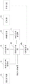
请参照图1,图1为本发明提供的一种步进电机的驱动装置的结构示意图,该装置包括:Please refer to Fig. 1, Fig. 1 is the structural representation of the driving device of a kind of stepper motor provided by the present invention, and this device comprises:
弦波信号发生电路1,用于基于预设步进信号和预设电流幅值输出预设电流弦波信号;A sine wave
第一输入端与步进电机连接,第二输入端与弦波信号发生电路1的输出端连接的数据反馈电路2,用于基于步进电机的当前电流弦波信号、预设电流幅值以及预设电流弦波信号输出实际补偿因子;The first input end is connected to the stepping motor, and the second input end is connected to the output end of the sine wave
第一输入端与数据反馈电路2的输出端连接,第二输入端与弦波信号发生电路1的输出端连接,输出端与步进电机的控制端连接的电机驱动电路3,用于在当前电流弦波信号的幅值小于预设电流弦波信号的幅值时基于实际补偿因子增大预设电流弦波信号的幅值,从而增大驱动电流;在当前电流弦波信号的幅值大于预设电流弦波信号的幅值时基于实际补偿因子减小预设电流弦波信号的幅值,从而减小驱动电流,并基于驱动电流对步进电机进行驱动。The first input end is connected with the output end of the
本实施例中,申请人考虑到若仅由根据预设步进信号和预设电流幅值生成的驱动电流来对步进电机进行驱动,可能会导致步进电机的线圈的反电动势对驱动电流产生抑制,从而使实际的驱动效果无法达到预设步进信号和预设电流幅值期望的驱动效果,进而可能会导致步进电机丢步,导致步进电机无法正常工作。In this embodiment, the applicant considers that if the stepper motor is driven only by the drive current generated according to the preset step signal and the preset current amplitude, it may cause the back electromotive force of the coil of the stepper motor to affect the drive current. Inhibition occurs, so that the actual driving effect cannot reach the desired driving effect of the preset step signal and preset current amplitude, which may cause the stepping motor to lose steps, resulting in the stepping motor not working properly.
为了解决上述技术问题,本申请公开了一种步进电机的驱动装置,包括弦波信号发生电路1、数据反馈电路2和电机驱动电路3,其中,弦波信号发生电路1能够根据预设步进信号和预设电流幅值输出预设电流弦波信号,但本申请并不仅基于预设电流弦波信号生成的驱动电流对步进电机进行驱动,而是还通过数据反馈电路2对步进电机的当前电流弦波信号进行采集,从而生成实际补偿因子,以使电机驱动电路3基于实际补偿因子对预设电流弦波信号进行调整,以根据调整后的预设电流弦波信号生成的驱动电流对步进电机进行驱动。可见,弦波信号发生电路1、数据反馈电路2和电机驱动电路3构成了一个闭环反馈,在当前电流弦波信号的幅值小于预设电流弦波信号的幅值时基于实际补偿因子增大预设电流弦波信号的幅值,从而增大驱动电流;在当前电流弦波信号的幅值大于预设电流弦波信号的幅值时基于实际补偿因子减小预设电流弦波信号的幅值,从而减小驱动电流,保证了输入至步进电机的驱动电流的幅值的稳定性,从而避免步进电机丢步,保证步进电机的稳定运行,降低步进电机运行时的噪声。In order to solve the above technical problems, the application discloses a stepper motor drive device, including a sine wave
综上,本申请中根据步进电机的当前电流弦波信号对预设电流弦波信号进行实时调整,从而能够在步进电机的当前电流弦波信号的幅值较小时增大驱动电流,在步进电机的当前电流弦波信号的幅值较大时减小驱动电流,以保证输入至步进电机的驱动电流的稳定,保证步进电机的稳定运行。To sum up, in this application, the preset current sinusoidal signal is adjusted in real time according to the current current sinusoidal signal of the stepping motor, so that the drive current can be increased when the amplitude of the current sinusoidal current signal of the stepping motor is small. When the amplitude of the current sine wave signal of the stepping motor is large, the driving current is reduced to ensure the stability of the driving current input to the stepping motor and the stable operation of the stepping motor.
在上述实施例的基础上:On the basis of above-mentioned embodiment:
作为一种优选的实施例,还包括:As a preferred embodiment, it also includes:
PWM(Pulse width modulation,脉冲宽度调制)信号输出装置4,用于输出预设PWM信号;PWM (Pulse width modulation, pulse width modulation)
数据反馈电路2包括:
输入端与步进电机连接的电流采集电路21,用于采集步进电机的当前电流弦波信号;The
第一输入端与电流采集电路21的输出端连接,第二输入端与弦波信号发生电路1的输出端连接,第三输入端与PWM信号输出装置4的输出端连接的数据处理电路22,用于基于当前电流弦波信号、预设电流幅值、预设电流弦波信号以及预设PWM信号输出实际补偿因子。The first input end is connected with the output end of the
本实施例中,数据反馈电路2在生成实际补偿因子时,是根据预设PWM信号的频率生成的,不仅能够使实际补偿因子更为准确,预设PWM信号对噪声的抵抗能力也较强。In this embodiment, the
此外,电流采集电路21能够对步进电机的当前电流弦波信号进行采集,并转换为数字信号,便于后续处理。In addition, the
需要说明的是,本申请中的数据处理电路22可以基于模糊算法或PI(比例积分)算法输出实际补偿因子,本申请对此不作限定。It should be noted that the
作为一种优选的实施例,数据处理电路22包括:As a preferred embodiment, the
数据调整模块220,用于将预设电流幅值乘以预设阈值,以输出调整后的预设电流幅值;A
输入正端与弦波信号发生电路1的输出端连接,输入负端与数据调整模块220的输出端连接的第一比较器221,用于在预设电流弦波信号大于调整后的预设电流幅值时输出第一电平;The positive input terminal is connected to the output terminal of the sine wave
输入正端与电流采集电路21的输出端连接,输入负端与数据调整模块220的输出端连接的第二比较器222,用于在当前电流弦波信号大于调整后的预设电流幅值时输出第二电平;The positive input terminal is connected to the output terminal of the
输入端与弦波信号发生电路1的输出端连接的过零判定模块223,用于在预设电流弦波信号过零点时输出过零脉冲信号;The zero-crossing
使能端与第一比较器221的输出端连接,时钟信号输入端与PWM信号输出装置4的输出端连接,复位端与过零判定模块223的输出端连接的理论值计数器224,用于自身的使能端接收到第一电平时对自身的时钟信号输入端接收到的预设PWM信号的周期数进行计数,在自身的使能端未接收到第一电平时停止计数,并在自身的复位端接收到过零脉冲信号时将自身计数的理论计数值发送至理论值计数锁存器226后清零;The enable end is connected with the output end of the
使能端与第二比较器222的输出端连接,时钟信号输入端与PWM信号输出装置4的输出端连接,复位端与过零判定模块223的输出端连接的实测值计数器225,用于自身的使能端接收到第二电平时对自身的时钟信号输入端接收到的预设PWM信号的周期数进行计数,在自身的使能端未接收到第二电平时停止计数,并在自身的复位端接收到过零脉冲信号时将自身计数的实测计数值发送至实测值计数锁存器227后清零;The enable end is connected with the output end of the
计数值输入端与理论值计数器224的输入端连接,时钟信号输入端与过零判定模块223的输出端连接的理论值计数锁存器226,用于在接收到过零脉冲信号时将理论计数值进行锁存;The count value input end is connected with the input end of the
计数值输入端与实测值计数器225的输入端连接,时钟信号输入端与过零判定模块223的输出端连接的实测值计数锁存器227,用于在接收到过零脉冲信号时将实测计数值进行锁存;The count value input end is connected with the input end of the measured
第一输入端与理论值计数锁存器226的输出端连接,第二输入端与实测值计数锁存器227的输出端连接的除法器228,用于确定实测计数值除以理论计数值的比值;The first input end is connected with the output end of the theoretical
输入端与除法器228的输出端连接,输出端为数据处理电路22的输出端的补偿因子确定模块229,用于基于比值和预设的比值与补偿因子的对应关系确定实际补偿因子;其中,补偿因子和比值成负相关。The input end is connected with the output end of the
请参照图2和图3,图2为本发明提供的一种电机反馈电路的结构示意图,图3为本发明提供的一种关于计算补偿因子的示意图。Please refer to FIG. 2 and FIG. 3 , FIG. 2 is a schematic structural diagram of a motor feedback circuit provided by the present invention, and FIG. 3 is a schematic diagram of calculating compensation factors provided by the present invention.
其中,申请人考虑到预设电流弦波信号的幅值和预设电流幅值是相等的,因此,先使数据调整模块220将预设电流幅值乘以预设阈值,以输出调整后的预设电流幅值,从而将预设电流弦波信号和调整后的预设电流幅值进行比较,并在预设电流弦波信号大于调整后的预设电流幅值时输出第一电平,以使理论值计数器224在接收到第一电平时开始计数,所计数值是根据自身的时钟信号输入端接收到的预设PWM信号的周期数进行计数,在自身的使能端未接收到第一电平时停止计数,并在自身的复位端接收到过零脉冲信号时将自身计数的理论计数值发送至理论值计数锁存器226后清零,可见,本申请中的理论计数值是在预设电流弦波信号大于调整后的预设电流幅值时的时间内预设PWM信号的周期数。Wherein, the applicant considers that the amplitude of the preset current sine wave signal is equal to the preset current amplitude, therefore, the
此外,将当前电流弦波信号和调整后的预设电流幅值进行比较,并在当前电流弦波信号大于调整后的预设电流幅值时输出第二电平,以使理实测计数器在接收到第二电平时开始计数,所计数值是根据自身的时钟信号输入端接收到的预设PWM信号的周期数进行计数,在自身的使能端未接收到第二电平时停止计数,并在自身的复位端接收到过零脉冲信号时将自身计数的理论计数值发送至理论值计数锁存器226后清零,可见,本申请中的实测计数值是在当前电流弦波信号大于调整后的预设电流幅值时的时间内预设PWM信号的周期数。In addition, compare the current current sine wave signal with the adjusted preset current amplitude, and output the second level when the current current sine wave signal is greater than the adjusted preset current amplitude, so that the actual measurement counter receives Start counting when it reaches the second level, the counted value is counted according to the number of cycles of the preset PWM signal received by its own clock signal input terminal, and stop counting when its own enable terminal does not receive the second level, and at When its own reset terminal receives the zero-crossing pulse signal, the theoretical count value of its own count is sent to the theoretical
需要说明的是,本申请中的调整后的预设电流幅值为预设电流阈值。It should be noted that the adjusted preset current amplitude in this application is the preset current threshold.
后续补偿因子确定模块229根据除法器228确定的实测计数值除以理论计数值所得到的比值和预设的比值与补偿因子的对应关系确定实际补偿因子,其中,比值越小,说明当前电流弦波信号的幅值越小,则所确定的实际补偿因子越大,以增大驱动电流,保证步进电机的稳定运行。Subsequent compensation
其中,比值与补偿因子的对应关系可以为某几个比值对应一个补偿因子,也可以为每个比值对应一个补偿因子,本申请对此不作限定。Wherein, the corresponding relationship between ratios and compensation factors may be that several ratios correspond to a compensation factor, or that each ratio corresponds to a compensation factor, which is not limited in the present application.
作为一种优选的实施例,电机驱动电路3包括:As a preferred embodiment, the
第一输入端与数据反馈电路2的输出端连接,第二输入端与弦波信号发生电路1的输出端连接的反馈调整装置31,用于在当前电流弦波信号的幅值小于预设电流弦波信号的幅值时基于实际补偿因子增大预设电流弦波信号的幅值,生成第一实际电流弦波信号;在当前电流弦波信号的幅值大于预设电流弦波信号的幅值时基于实际补偿因子减小预设电流弦波信号的幅值,生成第二实际电流弦波信号;The first input end is connected to the output end of the
第一输入端与反馈调整装置31的输出端连接,第二输入端与PWM信号输出装置4的输出端连接的PWM斩波器32,用于基于预设PWM信号将预设PWM信号转换为各个周期的占空比分别和第一实际电流弦波信号的各个脉冲一一对应的第一PWM波形信号;或基于预设PWM信号将预设PWM信号转换为各个周期的占空比分别和第二实际电流弦波信号的各个脉冲一一对应的第二PWM波形信号,第一PWM波形信号和第二PWM波形信号均为实际控制信号;The first input end is connected to the output end of the
输入端与PWM斩波器32的输出端连接,输出端与步进电机的控制端连接的逆变器33,用于基于实际控制信号输出驱动电流,以对步进电机进行驱动。The input end is connected to the output end of the
本实施例中本实施例中的电机驱动电路3中设有反馈调整装置31、PWM斩波器32和逆变器33,其中,反馈调整装置31在生成实际电流弦波信号后,PWM斩波器32将预设PWM信号的每个脉冲的占空比均调整为实际电流弦波信号的每个脉冲的幅值的大小,从而基于PWM波形信号对逆变器33进行控制,以使逆变器33输出和实际电流弦波信号对应的驱动电流,并对步进电机进行驱动。In this embodiment, the
作为一种优选的实施例,反馈调整装置31为乘法器,具体用于将预设电流弦波信号中各个脉冲信号的幅值和实际补偿因子相乘,以在当前电流弦波信号的幅值小于预设电流弦波信号的幅值时基于实际补偿因子增大预设电流弦波信号的幅值,生成第一实际电流弦波信号;在当前电流弦波信号的幅值大于预设电流弦波信号的幅值时基于实际补偿因子减小预设电流弦波信号的幅值,生成第二实际电流弦波信号。As a preferred embodiment, the
本申请中的反馈调整装置31为乘法器,乘法器通过将预设电流弦波信号中各个脉冲信号的幅值和实际补偿因子相乘,从而使后续基于实际电流弦波信号生成的驱动电流对步进电机进行驱动,保证了驱动电流的稳定性。The
作为一种优选的实施例,弦波信号发生电路1包括:As a preferred embodiment, the sine wave
弦波发生器11,用于基于预设步进信号生成基准弦波信号;A
输入端与弦波发生器11的输出端连接的弦波信号调整模块12,用于基于预设电流幅值对基准弦波信号的幅值进行调整,以输出预设电流弦波信号。The sine wave
本实施例中的弦波信号发生电路1包括弦波发生器11和弦波信号调整模块12,其中,弦波发生器11能够基于预设步进信号生成基准弦波信号,例如,预设步进信号为1/2步进时,生成脉冲和1/2步进对应的基准弦波信号。弦波信号调整模块12能够根据预设电流幅值对基准弦波信号的每一个脉冲的幅值进行调整,以输出预设电流弦波信号,其中预设电流弦波信号的幅值和预设电流幅值相等,预设电流弦波信号基于用户期望的电流弦波信号。The sine wave
其中,弦波信号调整模块12也可以为乘法器,以将基准弦波信号的每一个脉冲的幅值乘以预设电流幅值。Wherein, the sine wave
具体请参照图4,图4为本发明提供的一种电机的驱动装置的结构示意图,Please refer to FIG. 4 for details. FIG. 4 is a structural schematic diagram of a driving device for a motor provided by the present invention.
本发明提供了一种电机系统,包括如上述的步进电机的驱动装置,还包括步进电机。The present invention provides a motor system, including the above-mentioned driving device for a stepping motor, and further including a stepping motor.
对于本发明提供的一种电机系统的介绍请参照上述驱动装置实施例,本发明在此不再赘述。For the introduction of a motor system provided by the present invention, please refer to the above embodiment of the drive device, and the present invention will not be repeated here.
作为一种优选的实施例,步进电机为两相步进电机;As a preferred embodiment, the stepping motor is a two-phase stepping motor;
步进电机的驱动装置包括第一驱动装置和第二驱动装置,第一驱动装置与步进电机的第一相线圈连接,第二驱动装置与步进电机的第二相线圈连接。The driving device of the stepping motor includes a first driving device and a second driving device, the first driving device is connected with the first phase coil of the stepping motor, and the second driving device is connected with the second phase coil of the stepping motor.
本实施例中,申请人考虑到当步进电机为多相步进电机时,每一相都可连接一个本发明公开的驱动装置,从而对每一相线圈的驱动电流进行调整,进一步保证步进电机的稳定运行。In this embodiment, the applicant considers that when the stepping motor is a multi-phase stepping motor, each phase can be connected with a driving device disclosed in the present invention, so as to adjust the driving current of each phase coil to further ensure stepping. stable operation of the motor.
还需要说明的是,在本说明书中,诸如第一和第二等之类的关系术语仅仅用来将一个实体或者操作与另一个实体或操作区分开来,而不一定要求或者暗示这些实体或操作之间存在任何这种实际的关系或者顺序。而且,术语“包括”、“包含”或者其任何其他变体意在涵盖非排他性的包含,从而使得包括一系列要素的过程、方法、物品或者设备不仅包括那些要素,而且还包括没有明确列出的其他要素,或者是还包括为这种过程、方法、物品或者设备所固有的要素。在没有更多限制的情况下,由语句“包括一个……”限定的要素,并不排除在包括所述要素的过程、方法、物品或者设备中还存在另外的相同要素。It should also be noted that in this specification, relative terms such as first and second are only used to distinguish one entity or operation from another entity or operation, and do not necessarily require or imply that these entities or operations There is no such actual relationship or order between the operations. Furthermore, the term "comprises", "comprises" or any other variation thereof is intended to cover a non-exclusive inclusion such that a process, method, article, or apparatus comprising a set of elements includes not only those elements, but also includes elements not expressly listed. other elements of or also include elements inherent in such a process, method, article, or apparatus. Without further limitations, an element defined by the phrase "comprising a ..." does not exclude the presence of additional identical elements in the process, method, article or apparatus comprising said element.
对所公开的实施例的上述说明,使本领域专业技术人员能够实现或使用本发明。对这些实施例的多种修改对本领域的专业技术人员来说将是显而易见的,本文中所定义的一般原理可以在不脱离本发明的精神或范围的情况下,在其他实施例中实现。因此,本发明将不会被限制于本文所示的这些实施例,而是要符合与本文所公开的原理和新颖特点相一致的最宽的范围。The above description of the disclosed embodiments is provided to enable any person skilled in the art to make or use the invention. Various modifications to these embodiments will be readily apparent to those skilled in the art, and the general principles defined herein may be implemented in other embodiments without departing from the spirit or scope of the invention. Therefore, the present invention will not be limited to the embodiments shown herein, but is to be accorded the widest scope consistent with the principles and novel features disclosed herein.
Claims (6)
Priority Applications (1)
| Application Number | Priority Date | Filing Date | Title |
|---|---|---|---|
| CN202110667690.6A CN113315426B (en) | 2021-06-16 | 2021-06-16 | Driving device of stepping motor and motor system |
Applications Claiming Priority (1)
| Application Number | Priority Date | Filing Date | Title |
|---|---|---|---|
| CN202110667690.6A CN113315426B (en) | 2021-06-16 | 2021-06-16 | Driving device of stepping motor and motor system |
Publications (2)
| Publication Number | Publication Date |
|---|---|
| CN113315426A CN113315426A (en) | 2021-08-27 |
| CN113315426B true CN113315426B (en) | 2022-11-18 |
Family
ID=77378894
Family Applications (1)
| Application Number | Title | Priority Date | Filing Date |
|---|---|---|---|
| CN202110667690.6A Active CN113315426B (en) | 2021-06-16 | 2021-06-16 | Driving device of stepping motor and motor system |
Country Status (1)
| Country | Link |
|---|---|
| CN (1) | CN113315426B (en) |
Families Citing this family (4)
| Publication number | Priority date | Publication date | Assignee | Title |
|---|---|---|---|---|
| CN113809962B (en) * | 2021-11-18 | 2022-06-17 | 杭州瑞盟科技股份有限公司 | Stepping motor driving system and motor system |
| CN114499298B (en) * | 2021-12-31 | 2026-03-03 | 拓尔微电子股份有限公司 | Control method and control device for stepping motor, terminal equipment and storage medium |
| CN115833668B (en) * | 2022-11-01 | 2026-04-28 | 慧灵科技(深圳)有限公司 | Method and device for parameter identification of permanent magnet synchronous motor |
| CN117375462B (en) * | 2023-12-07 | 2024-03-08 | 深圳市恒永达科技股份有限公司 | Stepping motor calibration method, device, equipment and computer storage medium |
Family Cites Families (5)
| Publication number | Priority date | Publication date | Assignee | Title |
|---|---|---|---|---|
| JP2000184789A (en) * | 1998-12-11 | 2000-06-30 | Canon Inc | Driving method of stepping motor |
| EP1346461B1 (en) * | 2000-12-30 | 2008-07-30 | Hamilton Sundstrand Corporation | Commutation and velocity control system for a brushless dc motor |
| US9397597B2 (en) * | 2013-07-29 | 2016-07-19 | Texas Instruments Incorporated | Sensed motor winding current adapting blanking period between max/min values |
| CN111049437B (en) * | 2019-12-24 | 2021-09-21 | 浙江大华技术股份有限公司 | Method, device, equipment and medium for compensating back electromotive force voltage of stepping motor |
| CN112968637A (en) * | 2021-04-25 | 2021-06-15 | 杭州瑞盟科技有限公司 | Stepping motor driving device |
-
2021
- 2021-06-16 CN CN202110667690.6A patent/CN113315426B/en active Active
Also Published As
| Publication number | Publication date |
|---|---|
| CN113315426A (en) | 2021-08-27 |
Similar Documents
| Publication | Publication Date | Title |
|---|---|---|
| CN113315426B (en) | Driving device of stepping motor and motor system | |
| US9425720B2 (en) | Electric motor and motor control | |
| EP1901141B1 (en) | System and method for adjustable carrier waveform generator | |
| CN1977224A (en) | Control of Output Power Factor of Pulse Width Modulation Inverter | |
| JPH0667205B2 (en) | PWM pulse generator | |
| CN107834924B (en) | A kind of field weakening control method and device | |
| US6288514B1 (en) | Commutation method and apparatus for switched reluctance motor | |
| CN101682284A (en) | Pseudo current type 120-degree conduction inverter | |
| CN113809962B (en) | Stepping motor driving system and motor system | |
| CN111030528A (en) | Multi-ring voltage regulation control method for three-stage brushless synchronous motor | |
| JP4576739B2 (en) | Motor drive control device for pump | |
| CN111431441B (en) | Motor rotating speed control method and device, air conditioner and storage medium | |
| CN112968637A (en) | Stepping motor driving device | |
| CN107040176A (en) | A kind of novel stepper motor driving method and system | |
| CN115021623B (en) | Lead angle self-adaptive compensation circuit and brushless direct current motor | |
| CN116388615B (en) | Direct-current brushless motor broken line speed regulation control circuit and method | |
| CN214900703U (en) | Stepping motor driving device | |
| CN102522932B (en) | Direct-current brushless motor system of air conditioner and method for controlling number of revolution thereof | |
| CN110611462B (en) | Three-stage rotating speed indicating device and method for brushless direct current motor | |
| CN115562429A (en) | A power control method | |
| CN108448977A (en) | Method and device for field weakening control of DC motor | |
| CN110611461B (en) | Brushless direct current motor rotating speed indicating device and indicating method | |
| WO2007113859A1 (en) | Control device for an asynchronous electric motor | |
| JPH08256498A (en) | PWM inverter with dead time correction function | |
| RU12304U1 (en) | DEVICE FOR CONTROL OF INVERTER WITH WIDTH-PULSE MODULATION |
Legal Events
| Date | Code | Title | Description |
|---|---|---|---|
| PB01 | Publication | ||
| PB01 | Publication | ||
| SE01 | Entry into force of request for substantive examination | ||
| SE01 | Entry into force of request for substantive examination | ||
| CB02 | Change of applicant information |
Address after: 310000 room 701, building 9, No. 1, Weiye Road, Puyan street, Binjiang District, Hangzhou City, Zhejiang Province Applicant after: Hangzhou ruimeng Technology Co.,Ltd. Address before: 310053 room 701, building 9, No.1 Weiye Road, Puyan street, Binjiang District, Hangzhou City, Zhejiang Province Applicant before: HANGZHOU RUIMENG TECHNOLOGY Co.,Ltd. |
|
| CB02 | Change of applicant information | ||
| GR01 | Patent grant | ||
| GR01 | Patent grant | ||
| PE01 | Entry into force of the registration of the contract for pledge of patent right |
Denomination of invention: A drive device for a stepping motor and a motor system Granted publication date: 20221118 Pledgee: Ningbo Bank Co.,Ltd. Hangzhou Branch Pledgor: Hangzhou ruimeng Technology Co.,Ltd. Registration number: Y2026980005097 |
|
| PE01 | Entry into force of the registration of the contract for pledge of patent right |