Disclosure of Invention
The invention aims to provide a novel support-free rib key combination laminated plate structure easy to connect and a construction method thereof.
In order to achieve the purpose, the invention adopts the following technical scheme:
the invention provides a novel support-free easy-connection rib key combined laminated slab structure which comprises a plurality of slab bodies arranged side by side, wherein each slab body comprises a horizontal reinforcing mesh and a first concrete layer and a second concrete layer poured on the horizontal reinforcing mesh, the second concrete layer is positioned on the upper part of the first concrete layer, prefabricated shear keys and long prefabricated ribs are fixedly arranged on the horizontal reinforcing mesh side by side, the prefabricated shear keys are arranged at two ends of the long prefabricated ribs, one side end surfaces, close to each other, of the first concrete layers of two adjacent slab bodies are provided with lap joint reinforcing steel bar grooves, lap joint reinforcing steel bars are arranged in the lap joint reinforcing steel bar grooves in a sitting mode, and the parts, positioned on the outer sides of the lap joint reinforcing steel bar grooves, of the lap joint reinforcing steel bars are wrapped in the second concrete layer so as to splice the two slab bodies into a whole.
The plate body further comprises an I-shaped piece, and the I-shaped piece is fixedly arranged above the prefabricated shear key and the middle and long prefabricated rib.
And a second bolt hole is formed in the flange of the I-shaped part, the prefabricated shear key and the middle-long prefabricated rib are respectively provided with a first bolt hole, and bolts are inserted into the corresponding first bolt hole and the second bolt hole.
The I-shaped part is in a long strip shape, and two ends of the I-shaped part are respectively lapped on the prefabricated shear keys at two ends of the middle-long prefabricated rib and completely cover the prefabricated shear keys and the upper part of the middle-long prefabricated rib.
The I-shaped pieces are arranged in a sectional mode, are distributed above the prefabricated shear keys and the middle and long prefabricated ribs at equal intervals, and two ends of the I-shaped pieces located between the prefabricated shear keys and the middle and long prefabricated ribs are respectively lapped on the prefabricated shear keys and the middle and long prefabricated ribs.
The horizontal reinforcing mesh comprises a plurality of longitudinal stressed reinforcing steel bars arranged side by side and a plurality of transverse U-shaped reinforcing steel bars arranged on the longitudinal stressed reinforcing steel bars at equal intervals to form a grid structure.
The prefabricated shear key comprises a rectangular block-shaped concrete shear key and bottom embedded steel bars, the bottom embedded steel bars are parallel to the transverse U-shaped steel bars, one end of each bottom embedded steel bar is embedded in the rectangular block-shaped concrete shear key, and the other end of each bottom embedded steel bar is connected to the horizontal steel bar net in an overlapping mode.
The middle-long prefabricated rib comprises a bar-shaped concrete middle-long rib and a bottom embedded steel bar, the bottom embedded steel bar is parallel to the transverse U-shaped steel bar, one end of the bottom embedded steel bar is embedded in the bar-shaped concrete middle-long rib, and the other end of the bottom embedded steel bar is lapped on the horizontal steel bar net.
The bottom embedded steel bars are strip-shaped steel bars, L-shaped steel bars or T-shaped steel bars.
The construction method of the novel support-free rib and key combined laminated plate structure easy to connect comprises the following specific steps:
the method comprises the following steps: laying a bottom template at a preset position, and fixedly mounting the longitudinal stressed steel bars on the upper end surface of the bottom template;
step two: overlapping a transverse U-shaped reinforcing steel bar on the fixed longitudinal stressed reinforcing steel bar to form the horizontal reinforcing steel bar mesh;
step three: mounting prefabricated shear keys and a middle-long prefabricated rib on the horizontal steel bar net, wherein the prefabricated shear keys are arranged at two ends of the middle-long prefabricated rib;
step four: enclosing a first cast-in-place layer concrete template around the horizontal reinforcing mesh on which the prefabricated shear keys and the middle-long prefabricated ribs are installed, and connecting and fixing the first cast-in-place layer concrete template by using bar magnets to form a mouth-shaped structure;
step five: pouring concrete into the mouth-shaped structure formed in the fourth step to form the first concrete layer, wherein the first concrete layer wraps the prefabricated shear keys and the lower parts of the middle and long prefabricated ribs;
step six: tamping and surface-floating the first concrete layer, pressing the first concrete layer by using a tool to form the lapped reinforcing steel bar groove when the surface of the first concrete layer is initially set, carrying out surface-floating and galling treatment on the first concrete layer before the first concrete layer is finally set, and removing the first cast-in-place layer concrete template when the strength requirement is met to obtain a prefabricated bottom plate structure;
step seven: transporting the prefabricated bottom plate structure obtained in the sixth step to a preset position of a construction site for installation, placing lap-joint steel bars in splicing grooves of adjacent plates, supporting a second cast-in-place layer concrete template above the first concrete layer, and then pouring concrete in the second cast-in-place layer concrete template to form a second concrete layer, wherein the second concrete layer wraps the prefabricated shear keys and the upper parts of the middle and long prefabricated ribs, and the upper surface of the second concrete layer is flush with the upper end surfaces of the prefabricated shear keys and the middle and long prefabricated ribs;
step eight: and tamping and surface floating treatment are carried out on the poured second concrete layer, and a second cast-in-place layer concrete formwork is dismantled when the strength requirement is met to obtain a laminated plate structure formed by splicing a plurality of plate bodies.
In the first step, the longitudinal stressed steel bars can be replaced by longitudinal prestressed stressed steel bars, prestressed tensioning pedestals are installed at two ends of the laid bottom plate, the longitudinal prestressed stressed steel bars fixedly installed on the upper end face of the bottom template are tensioned by the tensioning pedestals to apply prestress, and correspondingly in the sixth step, when the template is removed, the longitudinal prestressed stressed steel bars are sheared and tensioned.
The longitudinal prestress stress steel bar is formed by winding steel bars or steel wires.
And seventhly, after the lap-joint steel bars are placed, pouring grouting materials into the splicing seams of the two prefabricated bottom plates by using the bottom sealing strips of the splicing seams of the two installed prefabricated bottom plates.
And seventhly, after the prefabricated bottom plate structure obtained in the sixth step is transported to a construction site, I-shaped pieces are installed above the prefabricated shear keys and the middle and long prefabricated ribs, the prefabricated bottom plate structure provided with the I-shaped pieces is hoisted to a preset position of the construction site to be installed, then the lap joint reinforcing steel bars are placed, after the maintenance and forming of the second concrete layer are completed in the eighth step, the I-shaped pieces are dismantled, and the laminated plate structure formed by splicing a plurality of plate bodies is obtained.
The I-shaped part is in a long strip shape, and two ends of the I-shaped part are respectively lapped on the prefabricated shear keys at two ends of the middle-long prefabricated rib and completely cover the prefabricated shear keys and the middle-long prefabricated rib; or the I-shaped pieces are distributed in a sectional mode, are distributed above the prefabricated shear keys and the middle and long prefabricated ribs at equal intervals, and two ends of the I-shaped pieces positioned between the prefabricated shear keys and the middle and long prefabricated ribs are respectively lapped on the prefabricated shear keys and the middle and long prefabricated ribs.
The flange of the I-shaped part is provided with a second bolt hole, the prefabricated shear key and the middle-long prefabricated rib are respectively provided with a first bolt hole, the first bolt hole and the second bolt hole are correspondingly inserted with bolts, each bolt comprises a screw rod and a nut, the screw rod is provided with threads, and one end of the screw rod is fixedly connected with the nut, so that the I-shaped part is fixedly connected to the prefabricated shear key and the middle-long prefabricated rib.
The novel support-free rib key combination laminated plate structure easy to connect and the construction method thereof have the beneficial effects that:
(1) innovation of prefabricated base plate structure
The prefabricated bottom plate structure with the middle long ribs and the rib key combination is provided, compared with the prefabricated bottom plate with the long ribs researched and applied at present, the prefabricated bottom plate with the middle long ribs and the rib key combination is mainly different in that the length of the ribs is reduced according to the bending moment characteristic of a simply supported beam, the ribs can be prefabricated, the upper surfaces of the ribs and the upper surfaces of the laminated plates are located on the same plane, and the prefabricated bottom plate structure with the middle long ribs and the rib key combination has the advantages that: the pipeline is convenient to pass through; the ribs are higher, and the bending resistance is better; when in construction, I-shaped steel (aluminum) can be temporarily attached to the upper surface of the rib or the rib key, so that the bending resistance of the prefabricated bottom plate is further improved, and the support-free applicable span is larger. Therefore, the prefabricated bottom plate structure provided by the project has obvious innovation.
(2) Innovation of construction method
In order to realize the support-free construction of the large-span laminated slab prefabricated bottom plate, the project provides a construction method that temporary I-shaped steel (aluminum) is attached to the upper surfaces of ribs or rib keys in the construction stage, and the post-cast concrete is removed after the post-cast concrete reaches the expected strength. The construction cost and the construction difficulty of the additional temporary I-shaped steel (aluminum) are far lower than those of the arrangement support. The construction method is obviously different from the traditional construction method, so that the construction method is an important innovation of the project.
(3) Innovation of splicing structure and method for prefabricated bottom plate of laminated slab
For realizing two-way board biography power, superimposed sheet prefabricated bottom plate is when the concatenation, there are the work progress and need construct many teams and groups, the piece width is big or can not satisfy rigidity each other nature scheduling problem, in order to solve above-mentioned problem, this project has proposed neotype superimposed sheet prefabricated bottom plate mosaic structure and method, it reserves the recess at the board side of superimposed sheet prefabricated bottom plate, during the prefabricated bottom plate concatenation, at first adopt sponge adhesive tape shutoff at two adjacent bottom plate bottoms, then put into U type muscle in the recess, at last pour into grout material in adjacent bottom plate gap and recess, realize superimposed sheet two-way biography power, it has the construction portably, it passes the power effectual, the little difficult advantage such as fracture of piece, can effectively solve above-mentioned problem. Therefore, the splicing structure and the splicing method of the prefabricated bottom plate, which are provided by the project, have obvious innovation.
Drawings
FIG. 1 is a schematic view of a longitudinally stressed steel bar;
FIG. 2 is a schematic structural view of a transverse U-shaped rib;
FIG. 3 is an enlarged schematic view of a prefabricated shear key structure;
FIG. 4 is an enlarged schematic view of a medium length preform rib structure;
FIG. 5 is a schematic view of a structure with prefabricated shear keys and long prefabricated ribs installed;
FIG. 6 is a schematic structural diagram of a first cast-in-place layer concrete formwork;
FIG. 7 is a schematic illustration of the construction of a first layer of concrete;
FIG. 8 is a schematic structural view of a first layer of concrete with the grooves of the reinforcing bars pressed;
FIG. 9 is a schematic structural view of the assembly of the stacked plates;
FIG. 10 is an enlarged schematic view of the structure at the seam;
FIG. 11 is a schematic view of a second concrete layer being poured;
FIG. 12 is a schematic view of a longitudinally prestressed reinforcement bar;
FIG. 13 is an enlarged schematic view of a prefabricated shear key structure with first bolt holes;
FIG. 14 is an enlarged schematic view of a long and medium preform rib structure with first bolt holes;
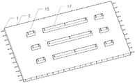
FIG. 15 is a structural view illustrating the installation of prefabricated shear keys with first bolt holes and a middle-long prefabricated rib with first bolt holes;
FIG. 16 is a schematic view of a structure enclosing a first cast-in-place layer concrete form with first bolt holes;
FIG. 17 is a schematic view of a structure with first bolt holes for placing a first layer of concrete;
FIG. 18 is a schematic view of a first layer of concrete with a pressed groove of structural rebar with a first bolt hole;
FIG. 19 is a schematic view of a construction of a laminated slab with an I-shaped member;
FIG. 20 is a schematic structural view of an I-shaped member;
FIG. 21 is a schematic view of the anchor bolt;
FIG. 22 is a schematic view of the construction of the assembly of the laminated slab with the I-shaped member;
FIG. 23 is a schematic view of a laminated slab with I-shaped members for placing a second concrete layer;
FIG. 24 is a schematic view of the construction of the composite slab with the I-shaped members removed;
FIG. 25 is a schematic view of the installation of the long I-shaped member to the prefabricated shear key and the middle-long prefabricated rib;
FIG. 26 is a schematic structural view of a multi-span installation of a sectional I-shaped member to a prefabricated shear key and a long precast rib;
in the figure, 1-longitudinal stressed steel bar; 2-transverse U-shaped steel bars; 3-prefabricating shear keys; 4-concrete shear key; 5-embedding reinforcing steel bars at the bottom; 6-middle long prefabricated ribs; 7-long concrete middle ribs; 8-a first cast-in-place layer concrete template; 9-a first concrete layer; 10-lapping a steel bar groove; 11-overlapping the reinforcing steel bars; 12-a second concrete layer; 13-longitudinal prestressed stressed steel bars; 14-an i-shaped piece; 15-prefabricated shear key with first bolt hole; 16-a first bolt hole; 17-a medium-length prefabricated rib with a first bolt hole; 18-a second bolt hole; 19-bolt; 20-a screw; 21-screw cap.
Detailed Description
The technical solutions in the embodiments of the present invention will be clearly and completely described below with reference to the drawings in the embodiments of the present invention, and it is obvious that the described embodiments are only a part of the embodiments of the present invention, and not all of the embodiments. All other embodiments, which can be derived by a person skilled in the art from the embodiments given herein without making any creative effort, shall fall within the protection scope of the present invention.
It should be noted that all the directional indicators (such as up, down, left, right, front, and rear … …) in the embodiment of the present invention are only used to explain the relative position relationship between the components, the movement situation, etc. in a specific posture (as shown in the drawing), and if the specific posture is changed, the directional indicator is changed accordingly.
In addition, the descriptions related to "first", "second", etc. in the present invention are for descriptive purposes only and are not to be construed as indicating or implying relative importance or implicitly indicating the number of technical features indicated. Thus, a feature defined as "first" or "second" may explicitly or implicitly include at least one such feature. In addition, technical solutions between various embodiments may be combined with each other, but must be realized by a person skilled in the art, and when the technical solutions are contradictory or cannot be realized, such a combination should not be considered to exist, and is not within the protection scope of the present invention.
The invention provides a novel support-free easy-connection rib key combined laminated slab structure which comprises a plurality of slab bodies arranged side by side, wherein each slab body comprises a horizontal reinforcing mesh and a first concrete layer 9 and a second concrete layer 12 poured on the horizontal reinforcing mesh, the second concrete layer 12 is positioned on the upper part of the first concrete layer 9, prefabricated shear keys 3 and a middle-long prefabricated rib 6 are fixedly arranged on the horizontal reinforcing mesh side by side, the prefabricated shear keys 3 are arranged at two ends of the middle-long prefabricated rib 6, one side end surfaces, close to each other, of the first concrete layers 9 of two adjacent slab bodies are provided with lap joint reinforcing grooves 10, lap joint reinforcing steel bars 11 are arranged in the lap joint reinforcing grooves 10 in a sitting mode, and parts, positioned on the outer sides of the lap joint reinforcing grooves 10, of the lap joint reinforcing steel bars 11 are covered in the second concrete layer 12 so as to integrally splice the two slab bodies. Furthermore, the plate body further comprises an I-shaped part 14, and the I-shaped part 14 is fixedly arranged above the prefabricated shear key 3 and the long prefabricated rib 6.
The first embodiment is as follows:
the invention provides a novel support-free rib and key combination laminated plate structure easy to connect, as shown in fig. 1, fig. 2, fig. 3, fig. 4, fig. 5, fig. 6, fig. 7, fig. 8, fig. 9, fig. 10 and fig. 11, comprising: the horizontal reinforcing mesh comprises a longitudinal stress reinforcing steel bar 1 and a transverse U-shaped bar 2 lapped on the longitudinal stress reinforcing steel bar, each prefabricated shear key 3 comprises a concrete shear key 4 and a bottom embedded reinforcing steel bar 5, each middle-long prefabricated rib 6 comprises a concrete middle-long rib 7 and a bottom embedded reinforcing steel bar 5, the bottom embedded reinforcing steel bar 5 is a strip-shaped reinforcing steel bar, an L-shaped reinforcing steel bar, a T-shaped reinforcing steel bar or other shapes meeting the use requirement, a first concrete layer 9 is poured on the lower portions of the horizontal reinforcing mesh, the prefabricated shear keys 3 and the middle-long prefabricated ribs 6, a lap joint reinforcing steel bar groove 10 is reserved on the surface of the first concrete layer 9, a second concrete layer 12 is poured on the upper portions of the prefabricated shear keys 3 and the middle-long prefabricated ribs 6, the concrete in the integral structure is poured twice, and the first concrete layer 9 and the surface lap joint reinforcing steel bar groove 10 are reserved in a factory, the prefabricated shear key is suitable for industrial mass production, the pouring and reserved quality is guaranteed, the second concrete layer 12 is poured on a construction site, the prefabricated shear key 3 and the middle-long prefabricated rib 6 are installed on the horizontal reinforcing steel bar net, and the prefabricated shear key is suitable for a large-span building plate structure.
Further, in this embodiment, one end of the bottom embedded steel bar 5 is embedded in the concrete shear key 4 or the concrete medium-long rib 7, and the other end is lapped on the horizontal steel bar net and is bound and connected by a steel bar binding wire.
Further, in the present embodiment, as shown in fig. 4, the long rib 7 in the concrete has a rectangular cross section.
Further, in this embodiment, the longitudinal steel bars and the transverse U-shaped bars 2 are bound and fixed by steel bar binding wires.
Further, in this embodiment, the side edges of the surface of the first concrete layer 9 are pressed by a tool during initial setting to form the overlapping steel bar groove 10.
Further, as shown in fig. 1, the longitudinal steel bar is a longitudinal stressed steel bar 1.
The construction method of the novel support-free rib and key combined laminated plate structure easy to connect comprises the following specific steps:
the method comprises the following steps: laying a bottom template at a preset position, and fixedly installing a plurality of longitudinal stress steel bars 1 which are arranged side by side on the upper end surface of the bottom template;
step two: a plurality of transverse U-shaped steel bars 2 arranged in an equidistant way are lapped on the fixed longitudinal stress steel bar 1, and the intersection of the longitudinal stress steel bar 1 and the transverse U-shaped steel bars 2 is bound and fixed by steel bar binding wires and is in a grid structure to form a horizontal steel bar mesh;
step three: the prefabricated shear key 3 comprises a concrete shear key 4 and a concrete shear key bottom embedded steel bar 5, and the bottom embedded steel bar 5 is arranged perpendicular to the length direction of the shear key to form the prefabricated shear key 3;
step four: the middle-long prefabricated rib 6 comprises a concrete middle-long rib 7 and a concrete middle-long rib bottom embedded steel bar 6, and the bottom embedded steel bar 6 is perpendicular to the length direction of the middle-long rib to form the middle-long prefabricated rib 6;
step five: as shown in fig. 5, the prefabricated shear keys 3 and the middle-long prefabricated ribs 6 are installed on the horizontal steel bar net, and the bottom embedded steel bars 6 of the prefabricated shear keys 3 and the middle-long prefabricated ribs 6 are placed in parallel to the transverse U-shaped bars 2 and are bound and fixed by steel bar binding wires;
step six: as shown in fig. 6, a first cast-in-place layer concrete formwork 8 is arranged around the horizontal reinforcing mesh on which the prefabricated shear keys 3 and the middle-long prefabricated ribs 6 are installed, and the first cast-in-place layer concrete formwork 8 is connected and fixed by using bar magnets, so that the first cast-in-place layer concrete formwork 8 is arranged to form a mouth-shaped structure;
step seven: as shown in fig. 7, pouring concrete into the mouth-shaped structure with the prefabricated shear keys 3 and the middle and long prefabricated ribs 6 installed, to form a first concrete layer 9, generally having a thickness of not less than 60mm, wherein the first concrete layer 18 wraps the prefabricated shear keys 3 and the lower parts of the middle and long prefabricated ribs 6;
step eight: and tamping and surface floating treatment are carried out on the first concrete layer 9. As shown in fig. 8, when the first concrete layer 9 is initially set, the first concrete layer 9 is pressed by a tool to form the overlapping steel bar groove 10, and before the first concrete layer 9 is finally set, the first concrete layer is subjected to surface smoothing and roughening treatment. So that the depth of the rough concave-convex part on the surface is not less than 4mm, when the strength requirement is met, the template is removed (when the strength of the test block is maintained under the same condition to reach 75% of the designed concrete cube compressive strength), and the prefabricated bottom plate structure is obtained;
step nine: and (3) transporting the prefabricated bottom plate structure obtained in the step eight to a preset position of a construction site for installation, placing lap joint reinforcing steel bars 11 as shown in figures 9 and 10, placing sealing strips at the bottoms of splicing seams of two installed prefabricated bottom plates, pouring high-strength grouting materials into the splicing seams of the two prefabricated bottom plates, supporting a second cast-in-place layer concrete formwork above the first concrete layer 9 after the high-strength grouting materials meet the strength requirement, then pouring concrete in the second cast-in-place layer concrete formwork to form a second concrete layer 12, wrapping the upper parts of the prefabricated shear keys 3 and the middle and long prefabricated ribs 6 by the second concrete layer 12, tamping and surface-floating the poured second concrete layer 12, removing the formwork when the strength requirement is met, and obtaining a laminated plate structure as shown in figure 11.
Example two:
in this embodiment, the longitudinal stressed steel bar 1 in the first embodiment is replaced by a longitudinal prestressed stressed steel bar 13. Specifically, as shown in fig. 2, 3, 4, 5, 6, 7, 8, 9, 10, 11, and 12:
in the first step of the first embodiment, a bottom form is laid at a predetermined position, two ends of the laid bottom plate are also provided with a prestressed tensioning table base, and a longitudinal prestressed stressed steel bar 13 fixedly arranged on the upper end surface of the bottom form is tensioned by the tensioning table base to apply prestress; in the eighth step of the first embodiment, the first concrete layer 9 is tamped and surface-smoothed, when the first concrete layer 9 is initially set, the first concrete layer is pressed by a tool to form the overlapping steel bar groove 10, and before the first concrete layer 9 is finally set, the first concrete layer is surface-smoothed and roughened to make the rough concave-convex depth of the surface not less than 4mm, and the formwork is removed when the strength requirement is met (when the strength of the test block under the same condition reaches 75% of the designed concrete cube compressive strength). Correspondingly, when the prefabricated bottom plate structure is disassembled, the longitudinal prestress stressed steel bar 13 is subjected to shearing and stretching to obtain the prefabricated bottom plate structure.
The other specific steps and processes are the same as those of the embodiment, the embodiment is suitable for a larger-span building plate structure, and the longitudinal prestressed reinforcement 13 can be formed by winding reinforcement or steel wires.
Example three:
in the embodiment, i-shaped parts 14 are arranged on the prefabricated shear key 3 and the middle-long prefabricated rib 6 in the first embodiment. Specifically, as shown in fig. 1, 2, 10, 13, 14, 15, 16, 17, 18, 19, 20, 21, 22, 23, and 24:
in the third step of the first embodiment, the prefabricated shear key 15 with the first bolt hole, the prefabricated shear key 3 with the first bolt hole 15 includes a concrete shear key 4, a first bolt hole 16, and a concrete shear key bottom embedded steel bar 5, and the bottom embedded steel bar 5 is arranged perpendicular to the length direction of the shear key to form the prefabricated shear key 15 with the first bolt hole; the middle-long prefabricated rib 17 with the first bolt hole is formed, the middle-long prefabricated rib 6 with the first bolt hole 17 comprises a concrete middle-long rib 7, a first bolt hole 16 and a concrete middle-long rib bottom embedded steel bar 5, and the bottom embedded steel bar 5 is perpendicular to the length direction of the middle-long rib to form the middle-long prefabricated rib 17 with the first bolt hole;
in the fifth step of the first embodiment, as shown in fig. 15, the prefabricated shear key 15 with the first bolt hole and the long and middle prefabricated rib 17 with the first bolt hole are installed on the horizontal steel bar net, and the prefabricated shear key 3 and the bottom embedded steel bars 5 of the long and middle prefabricated rib 6 are placed in parallel to the transverse U-shaped bar 2 and are bound and fixed by using steel bar wires;
in the sixth step of the first embodiment, as shown in fig. 16, a first cast-in-place layer concrete formwork 8 is arranged around the horizontal reinforcing mesh on which the prefabricated shear keys 3 and the middle-long prefabricated ribs 6 are installed, and the first cast-in-place layer concrete formwork 8 is connected and fixed by using bar magnets, so that the first cast-in-place layer concrete formwork 8 is arranged to form a mouth-shaped structure;
in the seventh step of the first embodiment, as shown in fig. 17, concrete is poured into the mouth-shaped structure with the prefabricated shear keys 3 and the long prefabricated ribs 6 installed, so as to form a first concrete layer 9, generally having a thickness of not less than 60mm, and the first concrete layer 18 wraps the lower portions of the prefabricated shear keys 3 and the long prefabricated ribs 6;
in step eight of the first embodiment, the first concrete layer 9 is tamped and surface-leveled. As shown in fig. 18, when the first concrete layer 9 is initially set, pressing with a tool to form an overlapping steel bar groove 10, before the first concrete layer 9 is finally set, performing surface smoothing and galling treatment to make the rough concave-convex depth of the surface not less than 4mm, and removing the template when the strength requirement is met (when the strength of the test block under the same condition reaches 75% of the designed concrete cube compressive strength), so as to obtain a prefabricated bottom plate structure;
in a ninth step of the first embodiment, the prefabricated baseboard structure in the eighth step is transported to a predetermined position of a construction site for installation, as shown in fig. 19, 20, and 21, i-shaped members 14 are disposed on the prefabricated shear keys 15 with the first bolt holes and the long prefabricated ribs 17 with the first bolt holes, second bolt holes 18 are opened on flange portions of the i-shaped members 14, bolts 19 are inserted into the first bolt holes 16 and the second bolt holes 18, each bolt 19 includes a screw 20 and a nut 21, a thread is disposed on the screw 20, and a nut 21 is fixedly connected to one end of the screw 20, so that the i-shaped members 14 are fixedly connected to the prefabricated shear keys 3 and the long prefabricated ribs 6. As shown in fig. 22, after the i-shaped member 14 is installed, hoisting the prefabricated base plate structure to a designated position, placing the lap reinforcement 11, pouring grouting materials into the splicing seams of the two installed prefabricated base plates, after the high-strength grouting materials meet the strength requirement, supporting a second cast-in-place layer concrete formwork above the first concrete layer 9, then pouring concrete into the second cast-in-place layer concrete formwork to form a second concrete layer 12, wrapping the prefabricated shear keys 3 and the upper parts of the middle and long prefabricated ribs 6 by the second concrete layer 12, tamping and surface-leveling the poured second concrete layer 12, removing the formwork when the strength requirement is met, and as shown in fig. 23, obtaining the laminated plate structure with the i-shaped member.
Step nine of the first embodiment further includes: and (4) dismantling the I-shaped part 14 with the laminated plate structure of the I-shaped part in the ninth step to obtain the laminated plate structure shown in figure 24, wherein the I-shaped part 14 is recovered in time after being dismantled and can be repeatedly used.
Specifically, the I-shaped part is in a long strip shape, and two ends of the I-shaped part are respectively lapped on the prefabricated shear keys at two ends of the middle-long prefabricated rib and completely cover the prefabricated shear keys 3 and the middle-long prefabricated rib 6; or the I-shaped pieces are arranged in a sectional mode, are distributed above the prefabricated shear keys 3 and the middle and long prefabricated ribs 6 at equal intervals, are positioned between the prefabricated shear keys 3 and the middle and long prefabricated ribs 6, and are respectively lapped on the prefabricated shear keys 3 and the middle and long prefabricated ribs 6 at two ends.
Further, in this embodiment, operating personnel can change I-shaped spare length rationally according to on-the-spot actual conditions, changes the bolt hole and reserves the position, changes the arrangement form. The inventor of the present invention only provides the arrangement shown in fig. 25 and 26 as a reference, and can set the long i-shaped member to be arranged in a full length and the short i-shaped member to be arranged in a multi-span manner, specifically, in the drawings of the present invention, only one structure of the transverse U-shaped rib 2, the overlapped steel bar 11 and the i-shaped member 14 is shown, but the present invention is not limited thereto, and other shapes meeting the use requirement can be applied to the laminated plate structure of the present invention.
The force transmission mechanism of the invention is as follows:
in the construction stage of the laminated slab, the prefabricated bottom plate bears live load in the construction stage and the weight of cast-in-place layer concrete, so that the prefabricated bottom plate needs to have the capability of resisting bending deformation and cracking, namely the prefabricated bottom plate needs to have enough bending rigidity, otherwise, a support needs to be arranged to increase the manufacturing cost. The precast concrete ribs and the shear keys are arranged on the precast bottom plate, so that the bending rigidity of the precast bottom plate can be effectively improved, and the temporary I-shaped parts are additionally arranged on the precast concrete ribs and the shear keys of the precast slab, so that the bending rigidity of the precast bottom plate can be further improved, and the support-free construction of a large-span laminated slab is realized.
The connection between the superimposed sheet is through setting up the recess at prefabricated bottom plate side, then places the overlap joint reinforcing bar in the recess that adjacent bottom plate is relative, then pastes the sponge adhesive tape back cover along piece length direction leads to long, at last pours into the grout material in the recess. And after the grouting material is solidified, pouring cast-in-place layer concrete. The grouting material can be effectively bonded with the concrete on the side edge of the prefabricated bottom plate, and the tensile stress between the concrete is transferred. The lap-jointed reinforcing steel bars are anchored in the grooves by the grouting materials and are anchored in the cast-in-place layer by the cast-in-place layer, and the tensile stress between the transverse U-shaped ribs of the two adjacent prefabricated base plates can be effectively transmitted, so that the bending moment is transmitted to form a stress state of the bidirectional plate.
Finally, it should be noted that: the above embodiments are only for illustrating the technical solutions of the present invention and not for limiting the same, and although the present invention is described in detail with reference to the above embodiments, those of ordinary skill in the art should understand that: modifications and equivalents may be made to the embodiments of the invention without departing from the spirit and scope of the invention, which is to be covered by the claims.