Disclosure of Invention
The invention provides a hydrate membrane device and a method for gas separation, aiming at overcoming the defects in the separation by a hydrate method.
The invention is realized by the following technical scheme:
a hydrate membrane device for gas separation comprises a gas steel cylinder, a gas buffer tank, a first temperature sensor, a first three-way valve, a first pressure sensor, a second stop valve, a second three-way valve, a second pressure sensor, a second temperature sensor, a hydrate membrane separator, a first product gas tank, a second product gas tank, a circulating water bath, a computer and a data acquisition instrument; the gas cylinder is connected with a gas buffer tank through a pipeline, a first temperature sensor is arranged on the gas buffer tank, the top of the gas buffer tank is connected with a gas inlet pipe orifice of the hydrate membrane separator through a pipeline, and a first three-way valve, a second stop valve and a second three-way valve are arranged on the pipeline between the gas buffer tank and the hydrate membrane separator; the top of the hydrate membrane separator is provided with a second temperature sensor; a side gas outlet pipe opening of the hydrate membrane separator is connected with a second product gas tank; the bottom outlet of the hydrate membrane separator is connected with a first product gas tank through a pipeline; the first three-way valve is connected with a first pressure sensor, the second three-way valve is connected with a second pressure sensor, the first temperature sensor, the first pressure sensor, the second pressure sensor and the second temperature sensor are respectively connected with a data acquisition instrument, and the data acquisition instrument is connected with a computer; the liquid inlet and the liquid outlet of the cooling jacket are connected with the circulating water bath through pipelines, and the liquid inlet and the liquid outlet of the membrane module cooling jacket are connected with the circulating water bath through pipelines; the device is used for realizing the pairingCH4/H2、CH4/CO2、CH4/N2、CO2/N2And (4) a mixed gas separation function.
Furthermore, the outer layer of the gas buffer tank is provided with a cooling jacket, and the top of the gas buffer tank is provided with an emptying valve.
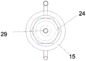
The hydrate membrane separator is composed of a membrane module cooling jacket, a membrane module, a seal head, an air inlet pipe, a baffle, a hydrate membrane pipe, a gasket and an air outlet, wherein the baffle supports the hydrate membrane pipe, the gasket seals the hydrate membrane pipe, and a feed gas enters from the air inlet pipe, permeates through the hydrate membrane pipe and then is discharged from the air outlet; the outer layer of the hydrate membrane separator is arranged on a membrane module cooling jacket; the membrane assembly is connected with the end enclosure through threads, and a temperature threaded hole is formed in the top of the end enclosure.
Further, the gasket is selected from a silicon rubber gasket, a tetrafluoro graphite gasket or a fluorine rubber gasket.
Furthermore, the hydrate membrane tube is made of porous materials with certain mechanical strength, porous ceramics, cordierite, molecular sieves or foam carbon are selected, and the pore size is 50 nm-2500 nm.
Furthermore, the invention also comprises a gas reducing valve, a first stop valve, a second stop valve, a third stop valve and a fourth stop valve; the gas pressure reducing valve and the first stop valve are positioned on a pipeline between the gas steel cylinder and the gas buffer tank; the second stop valve is positioned on a pipeline between the gas buffer tank and the hydrate membrane separator; the third stop valve is positioned on a pipeline between the hydrate membrane separator and the first product gas tank, and the fourth stop valve is positioned on a pipeline between the hydrate membrane separator and the second product gas tank.
In the device, the gas steel bottle, the gas relief pressure valve, first stop valve, the gas buffer tank links to each other in proper order, gas blow-down valve, first temperature sensor and first pressure sensor are being connected to the gas buffer tank top, be connected with first three-way valve between gas buffer tank and the hydrate membrane module, second stop valve and second three-way valve, hydrate membrane separator access connection has second pressure sensor and second temperature sensor, the inboard exit linkage of hydrate membrane tube has third stop valve and first product gas pitcher, the exit linkage in the hydrate membrane tube outside has fourth stop valve and second product gas pitcher. The circulating water bath is connected with the inlet and the outlet of the cooling jacket and the inlet and the outlet of the membrane module cooling jacket, so that the circulating flowing low-temperature fluid can be cooled conveniently. The gas separation device uses a data acquisition instrument and a computer to acquire corresponding data.
A hydrate membrane process for gas separation comprising the steps of:
(1) membrane tube pretreatment stage: placing the hydrate membrane tube in a drying container, and heating and vacuumizing the hydrate membrane tube at the temperature of 25-150 ℃ for 0.5-24 h to enable the hydrate membrane tube to meet the required vacuum degree requirement; then injecting deionized water in a vacuum state, cooling, transferring the hydrate membrane tube from the deionized water to the prepared additive solution, and standing for 0.5-48 h;
(2) preparing a hydrate membrane: and standing the hydrate film tube soaked in the solution for 1-48 h at-30-3 ℃ to generate a hydrate film, standing the hydrate film tube for 1-48 h at 0-15 ℃, and melting and converting ice possibly generated into a hydrate. Then, the hydrate membrane tube is placed in an environment with the temperature of-30-3 ℃ for stable solidification for 0.5-24 h, the water solution in the pores of the hydrate membrane tube is ensured to be completely hydrated, and finally the hydrate membrane tube is assembled in a hydrate membrane separator;
(3) a gas separation stage: opening a circulating water bath, and stabilizing the temperature of a gas buffer tank and a membrane assembly cooling jacket at-20-15 ℃; enabling the emptying valve to be in a closed state, opening the first stop valve, introducing mixed gas into the buffer tank, opening the second stop valve, and performing gas separation for a period of time; and opening a third stop valve, collecting the permeation gas by using the first product gas tank, opening a fourth stop valve, and collecting the residual permeation gas by using the second product gas tank.
In the above method, the additive comprises sII type hydrate thermodynamic promoter, half clathrate hydrate thermodynamic promoter; the additive is selected from tetrahydrofuran, quaternary ammonium salt, 1, 1-dichloro-1-monofluoroethane or cyclopentane.
In the method, the molar concentration of the mixed gas is 10-90%.
In the method, the pressure of the mixed gas introduced into the buffer tank is 0.5-5.0 MPa.
Compared with the prior art, the invention has the advantages that:
(1) the invention adopts the method that the hydrate is formed in the pores of the porous material, the aqueous solution is easy to form the hydrate in the porous structure, and the induction and generation time of the hydration reaction is shortened.
(2) The hydrate membrane of the invention adopts the principles of gas sieving and phase equilibrium to separate the mixed gas, and has high separation efficiency.
(3) Compared with the existing intermittent hydration separation method, the invention realizes the continuous gas separation operation, improves the production efficiency and has wide industrial application prospect.
Detailed Description
The following will further describe embodiments of the hydrate membrane module apparatus for gas separation according to the drawings of the present invention.
As shown in figures 1-3, a method for gas separationThe hydrate membrane device comprises a gas steel cylinder 1, a gas buffer tank 4, a first temperature sensor 7, a first three-way valve 8, a first pressure sensor 9, a second stop valve 10, a second three-way valve 11, a second pressure sensor 12, a second temperature sensor 13, a hydrate membrane separator 14, a first product gas tank 17, a second product gas tank 19, a circulating water bath 20, a computer 21 and a data acquisition instrument 22; the gas steel cylinder 1 is connected with a gas buffer tank 4 through a pipeline, a first temperature sensor 7 is arranged on the gas buffer tank 4, the top of the gas buffer tank 4 is connected with an air inlet pipe orifice of a hydrate membrane separator 14 through a pipeline, and a first three-way valve 8, a second stop valve 10 and a second three-way valve 11 are arranged on the pipeline between the gas buffer tank 4 and the hydrate membrane separator 14; the top of the hydrate membrane separator 14 is provided with a second temperature sensor 13; the side gas outlet pipe opening of the hydrate membrane separator 14 is connected with a second product gas tank 19; the outlet at the bottom of the hydrate membrane separator 14 is connected with a first product gas tank 17 through a pipeline; the first three-way valve 8 is connected with a first pressure sensor 9, the second three-way valve 11 is connected with a second pressure sensor 12, the first temperature sensor 7, the first pressure sensor 9, the second pressure sensor 12 and the second temperature sensor 13 are respectively connected with a data acquisition instrument 22, and the data acquisition instrument 22 is connected with a computer 21; a liquid inlet and a liquid outlet of the cooling jacket 5 are connected with the circulating water bath 20 through pipelines, and a liquid inlet and a liquid outlet of the membrane module cooling jacket 15 are connected with the circulating water bath 20 through pipelines; the device is used for realizing the CH pairing4/H2、CH4/CO2、CH4/N2、CO2/N2And (4) a mixed gas separation function. The outer layer of the gas buffer tank 4 is provided with a cooling jacket 5, and the top of the gas buffer tank 4 is provided with an emptying valve 6. The hydrate membrane separator 14 consists of a membrane module cooling jacket 15, a membrane module 23, a seal head 24, an air inlet pipe 25, a baffle 26, a hydrate membrane pipe 27, a gasket 28 and an air outlet 29, wherein the baffle 26 supports the hydrate membrane pipe 27, the gasket 28 seals the hydrate membrane pipe 27, and a feed gas enters from the air inlet pipe 25, permeates through the hydrate membrane pipe 27 and then is discharged from the air outlet 29; of the hydrate membrane separator 14The outer layer is arranged on the membrane module cooling jacket 15; the membrane assembly 23 is connected with the end enclosure 24 through threads, and the top of the end enclosure 24 is provided with a temperature threaded hole. The gasket 28 is selected from a silicone rubber gasket, a tetrafluoro graphite gasket or a fluorine rubber gasket. The hydrate membrane tube 27 is made of porous materials with certain mechanical strength, porous ceramics, cordierite, molecular sieves or foam carbon are selected, and the pore size is 50 nm-2500 nm. The present embodiment further includes a gas pressure reducing valve 2, a first cut-off valve 3, a second cut-off valve 10, a third cut-off valve 16, and a fourth cut-off valve 18; the gas pressure reducing valve 2 and the first stop valve 3 are positioned on a pipeline between the gas steel cylinder 1 and the gas buffer tank 4; the second stop valve 10 is positioned on a pipeline between the gas buffer tank 4 and the hydrate membrane separator 14; the third stop valve 16 is located on the conduit between the hydrate membrane separator 14 and the first product gas tank 17 and the fourth stop valve 18 is located on the conduit between the hydrate membrane separator 14 and the second product gas tank 19. The circulating water bath 20 is connected with the inlets and outlets of the hydrate film cooling jacket 15 and the cooling jacket 5, so that the circulating flowing low-temperature fluid can be cooled conveniently.
A hydrate membrane process for gas separation comprising the steps of:
(1) preparing an additive solution;
(2) membrane tube pretreatment stage: placing the hydrate membrane tube in a drying container, and heating and vacuumizing the hydrate membrane tube at the temperature of 25-150 ℃ for 0.5-24 h to enable the hydrate membrane tube to meet the required vacuum degree requirement; then injecting deionized water in a vacuum state, cooling, transferring the hydrate membrane tube from the deionized water to the prepared additive solution, and standing for 0.5-48 h;
(3) preparing a hydrate membrane: and standing the hydrate film tube soaked in the solution for 1-48 h at-30-3 ℃ to generate a hydrate film, standing the hydrate film tube for 1-48 h at 0-15 ℃, and melting and converting ice possibly generated into a hydrate. Then, the hydrate membrane tube is placed in an environment with the temperature of-30 ℃ to 3 ℃ for stable solidification for 0.5 to 24 hours, the water solution in the pores of the hydrate membrane tube is ensured to be completely hydrated, and finally the hydrate membrane tube is assembled in a hydrate membrane separator 14;
(4) a gas separation stage: opening a circulating water bath 20, and stabilizing the temperature of the gas buffer tank 4 and the membrane module cooling jacket 15 at-20-15 ℃; the emptying valve 6 is in a closed state, the first stop valve 3 is opened, mixed gas is introduced into the buffer tank 4, and the second stop valve 10 is opened to perform gas separation for a period of time; the third stop valve 16 is opened and permeate gas is collected using the first product gas tank 17. The fourth stop valve 18 is opened and the retentate gas is collected using the second product gas tank 19.
Example 1
(1) Preparing 5.56 mol% tetrahydrofuran solution;
(2) preparing a membrane tube by selecting a porous ceramic tube with a pore size of 50 nm;
(3) membrane tube pretreatment stage: placing the hydrate membrane tube in a drying container, and heating and vacuumizing the hydrate membrane tube at 60 ℃ for 4 hours to meet the required vacuum degree requirement; then injecting deionized water in a vacuum state, stopping vacuumizing and heating, cooling, and transferring the hydrate membrane tube from the deionized water to a prepared tetrahydrofuran solution for standing for 12 hours;
(4) preparing a hydrate membrane: standing the hydrate film tube soaked in the solution for 24h at-20 ℃ to completely generate a hydrate film, then standing the hydrate film tube for 24h at 0 ℃ to melt and convert ice possibly generated into a hydrate; then the hydrate membrane tube is placed in an environment with the temperature of minus 20 ℃ for stable solidification for 4h, and finally the hydrate membrane tube is assembled in a hydrate membrane separator 14 to ensure that all the water solution in the pores of the hydrate membrane tube forms hydrate;
(5) the circulating water bath 20 was opened and the gas surge tank 4 and membrane module cooling jacket 15 were stabilized at-10 ℃.
(6) Gas separation: the atmospheric valve 6 is closed, the first stop valve 3 is opened, and 80 mol% H is introduced2/CH4The mixed gas is introduced into the buffer tank 4, so that the gas pressure in the gas buffer tank 4 reaches 1.0 MPa. The second shut-off valve 10 is opened and gas separation is performed for a while.
(7) The third stop valve 16 is opened and permeate gas is collected using the first product gas tank 17. The fourth stop valve 18 is opened and the retentate gas is collected using the second product gas tank 19.
(8) Gas composition in the first product gas tank: h2Content of (2) 97.08 mol%, CH4The content of (B) is 2.92 mol%; gas composition in the second product gas tank: h2Content of (2) 32.68 mol%, CH4The content of (B) was 67.32 mol%.
Example 2
(1) Preparing 5.56 mol% tetrahydrofuran solution;
(2) selecting a carbon tube with a pore size of 600nm to prepare a membrane tube;
(3) membrane tube pretreatment stage: placing the hydrate membrane tube in a drying container, and heating and vacuumizing the hydrate membrane tube at 60 ℃ for 2 hours to meet the required vacuum degree requirement; then injecting deionized water in a vacuum state, cooling, transferring the hydrate membrane tube from the deionized water to the prepared additive solution, and standing for 12 hours;
(4) preparing a hydrate membrane: and (3) standing the hydrate film tube soaked in the solution at-20 ℃ for 12h to generate a hydrate film, and then standing the hydrate film tube at 0 ℃ for 12h to melt and convert ice possibly generated into a hydrate. Then the hydrate membrane tube is placed in an environment with the temperature of minus 20 ℃ for stable solidification for 12h, the water solution in the pores of the hydrate membrane tube is ensured to form the hydrate completely, and finally the hydrate membrane tube is assembled in a hydrate membrane separator 14;
(5) opening a circulating water bath 20, and stabilizing the temperature of the gas buffer tank 4 and the membrane module cooling jacket 15 at-5 ℃;
(6) gas separation: the atmospheric valve 6 is closed, the first stop valve 3 is opened, and 80 mol% H is introduced2/CH4The mixed gas is fed into the buffer tank 4, so that the gas pressure in the gas buffer tank 4 reaches 1.5 MPa. Opening the second stop valve 10 to perform gas separation for a period of time;
(7) the third stop valve 16 is opened and permeate gas is collected using the first product gas tank 17. Opening the fourth stop valve 18 and collecting the retentate gas using the second product gas tank 19;
(8) first productGas composition in the gas tank: h2Content of (3) is 97.41 mol%, CH4The content of (B) is 2.59 mol%; gas composition in the second product gas tank: h2Content of (3) is 29.13 mol%, CH4The content of (B) was 70.87 mol%.
Example 3
(1) Preparing 5.56 mol% 1, 1-dichloro-1-monofluoroethane solution;
(2) preparing a membrane tube by selecting a molecular sieve tube with a pore size of 1500 nm;
(3) membrane tube pretreatment stage: placing the hydrate membrane tube in a drying container, heating and vacuumizing the hydrate membrane tube at 80 ℃ for 8 hours to meet the required vacuum degree requirement; then injecting deionized water in a vacuum state, cooling, transferring the hydrate membrane tube from the deionized water to the prepared additive solution, and standing for 24 hours;
(4) preparing a hydrate membrane: and (3) standing the hydrate film tube soaked in the solution at-10 ℃ for 24h to generate a hydrate film, and then standing the hydrate film tube at 5 ℃ for 36h to melt and convert ice possibly generated into a hydrate. Then the hydrate membrane tube is placed in an environment with the temperature of minus 10 ℃ for stable solidification for 36h, the water solution in the pores of the hydrate membrane tube is ensured to form the hydrate completely, and finally the hydrate membrane tube is assembled in a hydrate membrane separator 14;
(5) opening a circulating water bath 20, and stabilizing the temperature of the gas buffer tank 4 and the membrane module cooling jacket 15 at-10 ℃;
(6) gas separation: the atmospheric valve 6 is closed, the first stop valve 3 is opened, and 80 mol% H is introduced2/CH4The mixed gas is fed into the buffer tank 4, so that the gas pressure in the gas buffer tank 4 reaches 2.0 MPa. Opening the second stop valve 10 to perform gas separation for a period of time;
(7) the third stop valve 16 is opened and permeate gas is collected using the first product gas tank 17. Opening the fourth stop valve 18 and collecting the retentate gas using the second product gas tank 19;
(8) gas composition in the first product gas tank: h2Content of (2) 98.52 mol%, CH4The content of (A) is 1.48 mol%; second product gas tankInner gas composition: h2Content of (2) is 24.53 mol%, CH4The content of (B) was 75.47 mol%.
Example 4
(1) Preparing 0.29 mol% tetrabutylammonium bromide solution;
(2) preparing a membrane tube by selecting a cordierite tube with a pore size of 2000 nm;
(3) membrane tube pretreatment stage: placing the hydrate membrane tube in a drying container, and heating and vacuumizing the hydrate membrane tube at 80 ℃ for 12 hours to meet the required vacuum degree requirement; then injecting deionized water in a vacuum state, cooling, transferring the hydrate membrane tube from the deionized water to the prepared additive solution, and standing for 36 hours;
(4) preparing a hydrate membrane: and (3) standing the hydrate film tube soaked in the solution at-5 ℃ for 36h to generate a hydrate film, and then standing the hydrate film tube at 5 ℃ for 48h to melt and convert ice possibly generated into a hydrate. Then the hydrate membrane tube is placed in an environment with the temperature of minus 5 ℃ for stable solidification for 24 hours, the water solution in the pores of the hydrate membrane tube is ensured to form a hydrate completely, and finally the hydrate membrane tube is assembled in a hydrate membrane separator 14;
(5) opening a circulating water bath 20, and stabilizing the temperature of the gas buffer tank 4 and the membrane module cooling jacket 15 at 0 ℃;
(6) gas separation: the atmospheric valve 6 is closed, the first stop valve 3 is opened, and 10 mol% CH is introduced4/CO2The mixed gas is introduced into the buffer tank 4, so that the gas pressure in the gas buffer tank 4 reaches 3.0 MPa. The second shut-off valve 10 is opened and gas separation is performed for a while.
(7) The third stop valve 16 is opened and permeate gas is collected using the first product gas tank 17. The fourth stop valve 18 is opened and the retentate gas is collected using the second product gas tank 19.
(8) Gas composition in the first product gas tank: CH (CH)4In an amount of 86.48 mol%, CO2The content of (A) is 13.52 mol%; gas composition in the second product gas tank: CH (CH)4Content of (3.77 mol%), CO2The content of (B) was 96.23 mol%.
Example 5
(1) Preparing 5.56 mol% 1, 1-dichloro-1-monofluoroethane solution;
(2) preparing a membrane tube by selecting a porous ceramic tube with the pore size of 2000 nm;
(3) membrane tube pretreatment stage: placing the hydrate membrane tube in a drying container, and heating and vacuumizing the hydrate membrane tube at 120 ℃ for 6 hours to meet the requirement of required vacuum degree; then injecting deionized water in a vacuum state, stopping vacuumizing and heating, cooling, and transferring the hydrate membrane tube from the deionized water to a prepared tetrahydrofuran solution for standing for 48 hours;
(4) preparing a hydrate membrane: standing the hydrate film tube soaked in the solution for 24h at-10 ℃ to completely generate a hydrate film, then standing the hydrate film tube for 24h at 0 ℃ to melt and convert ice possibly generated into a hydrate; then the hydrate membrane tube is placed in an environment with the temperature of minus 10 ℃ for stable solidification for 4h, and finally the hydrate membrane tube is assembled in a hydrate membrane separator 14 to ensure that all the water solution in the pores of the hydrate membrane tube forms hydrate;
(5) the circulating water bath 20 was opened and the gas surge tank 4 and membrane module cooling jacket 15 were stabilized at 0 ℃.
(6) Gas separation: the atmospheric valve 6 is closed, the first stop valve 3 is opened, and 10 mol% CH is introduced4/CO2The mixed gas is introduced into the buffer tank 4, so that the gas pressure in the gas buffer tank 4 reaches 4.0 MPa. The second shut-off valve 10 is opened and gas separation is performed for a while.
(7) The third stop valve 16 is opened and permeate gas is collected using the first product gas tank 17. The fourth stop valve 18 is opened and the retentate gas is collected using the second product gas tank 19.
(8) Gas composition in the first product gas tank: CH (CH)4Content of (2) is 84.66 mol%, CO2The content of (A) is 15.34 mol%; gas composition in the second product gas tank: CH (CH)4Content of (2) is 5.26 mol%, CO2The content of (B) was 94.74 mol%.
The above examples of the present invention are merely examples for clearly illustrating the present invention and are not intended to limit the embodiments of the present invention. Other variations and modifications will be apparent to persons skilled in the art in light of the above description. And are neither required nor exhaustive of all embodiments. Any modification, equivalent replacement, and improvement made within the spirit and principle of the present invention should be included in the protection scope of the claims of the present invention.