CN113286772A - Method for producing honeycombed body with inorganic filter deposit - Google Patents
Method for producing honeycombed body with inorganic filter deposit Download PDFInfo
- Publication number
- CN113286772A CN113286772A CN201980072251.1A CN201980072251A CN113286772A CN 113286772 A CN113286772 A CN 113286772A CN 201980072251 A CN201980072251 A CN 201980072251A CN 113286772 A CN113286772 A CN 113286772A
- Authority
- CN
- China
- Prior art keywords
- filtration article
- filtration
- inorganic
- equal
- binder
- Prior art date
- Legal status (The legal status is an assumption and is not a legal conclusion. Google has not performed a legal analysis and makes no representation as to the accuracy of the status listed.)
- Pending
Links
Images


Classifications
-
- C—CHEMISTRY; METALLURGY
- C04—CEMENTS; CONCRETE; ARTIFICIAL STONE; CERAMICS; REFRACTORIES
- C04B—LIME, MAGNESIA; SLAG; CEMENTS; COMPOSITIONS THEREOF, e.g. MORTARS, CONCRETE OR LIKE BUILDING MATERIALS; ARTIFICIAL STONE; CERAMICS; REFRACTORIES; TREATMENT OF NATURAL STONE
- C04B38/00—Porous mortars, concrete, artificial stone or ceramic ware; Preparation thereof
- C04B38/0006—Honeycomb structures
-
- B—PERFORMING OPERATIONS; TRANSPORTING
- B01—PHYSICAL OR CHEMICAL PROCESSES OR APPARATUS IN GENERAL
- B01D—SEPARATION
- B01D39/00—Filtering material for liquid or gaseous fluids
- B01D39/14—Other self-supporting filtering material ; Other filtering material
- B01D39/20—Other self-supporting filtering material ; Other filtering material of inorganic material, e.g. asbestos paper, metallic filtering material of non-woven wires
- B01D39/2027—Metallic material
- B01D39/2031—Metallic material the material being particulate
- B01D39/2034—Metallic material the material being particulate sintered or bonded by inorganic agents
-
- B—PERFORMING OPERATIONS; TRANSPORTING
- B01—PHYSICAL OR CHEMICAL PROCESSES OR APPARATUS IN GENERAL
- B01D—SEPARATION
- B01D39/00—Filtering material for liquid or gaseous fluids
- B01D39/14—Other self-supporting filtering material ; Other filtering material
- B01D39/20—Other self-supporting filtering material ; Other filtering material of inorganic material, e.g. asbestos paper, metallic filtering material of non-woven wires
- B01D39/2068—Other inorganic materials, e.g. ceramics
- B01D39/2072—Other inorganic materials, e.g. ceramics the material being particulate or granular
- B01D39/2079—Other inorganic materials, e.g. ceramics the material being particulate or granular otherwise bonded, e.g. by resins
-
- B—PERFORMING OPERATIONS; TRANSPORTING
- B01—PHYSICAL OR CHEMICAL PROCESSES OR APPARATUS IN GENERAL
- B01D—SEPARATION
- B01D46/00—Filters or filtering processes specially modified for separating dispersed particles from gases or vapours
- B01D46/0001—Making filtering elements
-
- B—PERFORMING OPERATIONS; TRANSPORTING
- B01—PHYSICAL OR CHEMICAL PROCESSES OR APPARATUS IN GENERAL
- B01D—SEPARATION
- B01D46/00—Filters or filtering processes specially modified for separating dispersed particles from gases or vapours
- B01D46/24—Particle separators, e.g. dust precipitators, using rigid hollow filter bodies
- B01D46/2403—Particle separators, e.g. dust precipitators, using rigid hollow filter bodies characterised by the physical shape or structure of the filtering element
- B01D46/2418—Honeycomb filters
-
- B—PERFORMING OPERATIONS; TRANSPORTING
- B05—SPRAYING OR ATOMISING IN GENERAL; APPLYING FLUENT MATERIALS TO SURFACES, IN GENERAL
- B05B—SPRAYING APPARATUS; ATOMISING APPARATUS; NOZZLES
- B05B7/00—Spraying apparatus for discharge of liquids or other fluent materials from two or more sources, e.g. of liquid and air, of powder and gas
- B05B7/14—Spraying apparatus for discharge of liquids or other fluent materials from two or more sources, e.g. of liquid and air, of powder and gas designed for spraying particulate materials
-
- B—PERFORMING OPERATIONS; TRANSPORTING
- B05—SPRAYING OR ATOMISING IN GENERAL; APPLYING FLUENT MATERIALS TO SURFACES, IN GENERAL
- B05B—SPRAYING APPARATUS; ATOMISING APPARATUS; NOZZLES
- B05B7/00—Spraying apparatus for discharge of liquids or other fluent materials from two or more sources, e.g. of liquid and air, of powder and gas
- B05B7/16—Spraying apparatus for discharge of liquids or other fluent materials from two or more sources, e.g. of liquid and air, of powder and gas incorporating means for heating or cooling the material to be sprayed
- B05B7/1606—Spraying apparatus for discharge of liquids or other fluent materials from two or more sources, e.g. of liquid and air, of powder and gas incorporating means for heating or cooling the material to be sprayed the spraying of the material involving the use of an atomising fluid, e.g. air
- B05B7/1613—Spraying apparatus for discharge of liquids or other fluent materials from two or more sources, e.g. of liquid and air, of powder and gas incorporating means for heating or cooling the material to be sprayed the spraying of the material involving the use of an atomising fluid, e.g. air comprising means for heating the atomising fluid before mixing with the material to be sprayed
-
- C—CHEMISTRY; METALLURGY
- C04—CEMENTS; CONCRETE; ARTIFICIAL STONE; CERAMICS; REFRACTORIES
- C04B—LIME, MAGNESIA; SLAG; CEMENTS; COMPOSITIONS THEREOF, e.g. MORTARS, CONCRETE OR LIKE BUILDING MATERIALS; ARTIFICIAL STONE; CERAMICS; REFRACTORIES; TREATMENT OF NATURAL STONE
- C04B26/00—Compositions of mortars, concrete or artificial stone, containing only organic binders, e.g. polymer or resin concrete
- C04B26/02—Macromolecular compounds
- C04B26/10—Macromolecular compounds obtained otherwise than by reactions only involving carbon-to-carbon unsaturated bonds
-
- C—CHEMISTRY; METALLURGY
- C04—CEMENTS; CONCRETE; ARTIFICIAL STONE; CERAMICS; REFRACTORIES
- C04B—LIME, MAGNESIA; SLAG; CEMENTS; COMPOSITIONS THEREOF, e.g. MORTARS, CONCRETE OR LIKE BUILDING MATERIALS; ARTIFICIAL STONE; CERAMICS; REFRACTORIES; TREATMENT OF NATURAL STONE
- C04B35/00—Shaped ceramic products characterised by their composition; Ceramics compositions; Processing powders of inorganic compounds preparatory to the manufacturing of ceramic products
- C04B35/01—Shaped ceramic products characterised by their composition; Ceramics compositions; Processing powders of inorganic compounds preparatory to the manufacturing of ceramic products based on oxide ceramics
- C04B35/16—Shaped ceramic products characterised by their composition; Ceramics compositions; Processing powders of inorganic compounds preparatory to the manufacturing of ceramic products based on oxide ceramics based on silicates other than clay
- C04B35/18—Shaped ceramic products characterised by their composition; Ceramics compositions; Processing powders of inorganic compounds preparatory to the manufacturing of ceramic products based on oxide ceramics based on silicates other than clay rich in aluminium oxide
- C04B35/195—Alkaline earth aluminosilicates, e.g. cordierite or anorthite
-
- C—CHEMISTRY; METALLURGY
- C04—CEMENTS; CONCRETE; ARTIFICIAL STONE; CERAMICS; REFRACTORIES
- C04B—LIME, MAGNESIA; SLAG; CEMENTS; COMPOSITIONS THEREOF, e.g. MORTARS, CONCRETE OR LIKE BUILDING MATERIALS; ARTIFICIAL STONE; CERAMICS; REFRACTORIES; TREATMENT OF NATURAL STONE
- C04B38/00—Porous mortars, concrete, artificial stone or ceramic ware; Preparation thereof
- C04B38/0006—Honeycomb structures
- C04B38/0016—Honeycomb structures assembled from subunits
- C04B38/0019—Honeycomb structures assembled from subunits characterised by the material used for joining separate subunits
-
- C—CHEMISTRY; METALLURGY
- C04—CEMENTS; CONCRETE; ARTIFICIAL STONE; CERAMICS; REFRACTORIES
- C04B—LIME, MAGNESIA; SLAG; CEMENTS; COMPOSITIONS THEREOF, e.g. MORTARS, CONCRETE OR LIKE BUILDING MATERIALS; ARTIFICIAL STONE; CERAMICS; REFRACTORIES; TREATMENT OF NATURAL STONE
- C04B38/00—Porous mortars, concrete, artificial stone or ceramic ware; Preparation thereof
- C04B38/0093—Other features
- C04B38/0096—Pores with coated inner walls
-
- C—CHEMISTRY; METALLURGY
- C04—CEMENTS; CONCRETE; ARTIFICIAL STONE; CERAMICS; REFRACTORIES
- C04B—LIME, MAGNESIA; SLAG; CEMENTS; COMPOSITIONS THEREOF, e.g. MORTARS, CONCRETE OR LIKE BUILDING MATERIALS; ARTIFICIAL STONE; CERAMICS; REFRACTORIES; TREATMENT OF NATURAL STONE
- C04B41/00—After-treatment of mortars, concrete, artificial stone or ceramics; Treatment of natural stone
- C04B41/009—After-treatment of mortars, concrete, artificial stone or ceramics; Treatment of natural stone characterised by the material treated
-
- C—CHEMISTRY; METALLURGY
- C04—CEMENTS; CONCRETE; ARTIFICIAL STONE; CERAMICS; REFRACTORIES
- C04B—LIME, MAGNESIA; SLAG; CEMENTS; COMPOSITIONS THEREOF, e.g. MORTARS, CONCRETE OR LIKE BUILDING MATERIALS; ARTIFICIAL STONE; CERAMICS; REFRACTORIES; TREATMENT OF NATURAL STONE
- C04B41/00—After-treatment of mortars, concrete, artificial stone or ceramics; Treatment of natural stone
- C04B41/45—Coating or impregnating, e.g. injection in masonry, partial coating of green or fired ceramics, organic coating compositions for adhering together two concrete elements
- C04B41/4505—Coating or impregnating, e.g. injection in masonry, partial coating of green or fired ceramics, organic coating compositions for adhering together two concrete elements characterised by the method of application
- C04B41/4535—Coating or impregnating, e.g. injection in masonry, partial coating of green or fired ceramics, organic coating compositions for adhering together two concrete elements characterised by the method of application applied as a solution, emulsion, dispersion or suspension
- C04B41/4543—Coating or impregnating, e.g. injection in masonry, partial coating of green or fired ceramics, organic coating compositions for adhering together two concrete elements characterised by the method of application applied as a solution, emulsion, dispersion or suspension by spraying, e.g. by atomising
-
- C—CHEMISTRY; METALLURGY
- C04—CEMENTS; CONCRETE; ARTIFICIAL STONE; CERAMICS; REFRACTORIES
- C04B—LIME, MAGNESIA; SLAG; CEMENTS; COMPOSITIONS THEREOF, e.g. MORTARS, CONCRETE OR LIKE BUILDING MATERIALS; ARTIFICIAL STONE; CERAMICS; REFRACTORIES; TREATMENT OF NATURAL STONE
- C04B41/00—After-treatment of mortars, concrete, artificial stone or ceramics; Treatment of natural stone
- C04B41/45—Coating or impregnating, e.g. injection in masonry, partial coating of green or fired ceramics, organic coating compositions for adhering together two concrete elements
- C04B41/50—Coating or impregnating, e.g. injection in masonry, partial coating of green or fired ceramics, organic coating compositions for adhering together two concrete elements with inorganic materials
- C04B41/5025—Coating or impregnating, e.g. injection in masonry, partial coating of green or fired ceramics, organic coating compositions for adhering together two concrete elements with inorganic materials with ceramic materials
- C04B41/5031—Alumina
-
- C—CHEMISTRY; METALLURGY
- C04—CEMENTS; CONCRETE; ARTIFICIAL STONE; CERAMICS; REFRACTORIES
- C04B—LIME, MAGNESIA; SLAG; CEMENTS; COMPOSITIONS THEREOF, e.g. MORTARS, CONCRETE OR LIKE BUILDING MATERIALS; ARTIFICIAL STONE; CERAMICS; REFRACTORIES; TREATMENT OF NATURAL STONE
- C04B41/00—After-treatment of mortars, concrete, artificial stone or ceramics; Treatment of natural stone
- C04B41/80—After-treatment of mortars, concrete, artificial stone or ceramics; Treatment of natural stone of only ceramics
- C04B41/81—Coating or impregnation
- C04B41/85—Coating or impregnation with inorganic materials
- C04B41/87—Ceramics
-
- B—PERFORMING OPERATIONS; TRANSPORTING
- B01—PHYSICAL OR CHEMICAL PROCESSES OR APPARATUS IN GENERAL
- B01D—SEPARATION
- B01D2239/00—Aspects relating to filtering material for liquid or gaseous fluids
- B01D2239/04—Additives and treatments of the filtering material
- B01D2239/0407—Additives and treatments of the filtering material comprising particulate additives, e.g. adsorbents
-
- B—PERFORMING OPERATIONS; TRANSPORTING
- B01—PHYSICAL OR CHEMICAL PROCESSES OR APPARATUS IN GENERAL
- B01D—SEPARATION
- B01D2239/00—Aspects relating to filtering material for liquid or gaseous fluids
- B01D2239/04—Additives and treatments of the filtering material
- B01D2239/0471—Surface coating material
- B01D2239/0478—Surface coating material on a layer of the filter
-
- B—PERFORMING OPERATIONS; TRANSPORTING
- B82—NANOTECHNOLOGY
- B82Y—SPECIFIC USES OR APPLICATIONS OF NANOSTRUCTURES; MEASUREMENT OR ANALYSIS OF NANOSTRUCTURES; MANUFACTURE OR TREATMENT OF NANOSTRUCTURES
- B82Y30/00—Nanotechnology for materials or surface science, e.g. nanocomposites
-
- B—PERFORMING OPERATIONS; TRANSPORTING
- B82—NANOTECHNOLOGY
- B82Y—SPECIFIC USES OR APPLICATIONS OF NANOSTRUCTURES; MEASUREMENT OR ANALYSIS OF NANOSTRUCTURES; MANUFACTURE OR TREATMENT OF NANOSTRUCTURES
- B82Y40/00—Manufacture or treatment of nanostructures
-
- C—CHEMISTRY; METALLURGY
- C04—CEMENTS; CONCRETE; ARTIFICIAL STONE; CERAMICS; REFRACTORIES
- C04B—LIME, MAGNESIA; SLAG; CEMENTS; COMPOSITIONS THEREOF, e.g. MORTARS, CONCRETE OR LIKE BUILDING MATERIALS; ARTIFICIAL STONE; CERAMICS; REFRACTORIES; TREATMENT OF NATURAL STONE
- C04B2111/00—Mortars, concrete or artificial stone or mixtures to prepare them, characterised by specific function, property or use
- C04B2111/00474—Uses not provided for elsewhere in C04B2111/00
- C04B2111/00793—Uses not provided for elsewhere in C04B2111/00 as filters or diaphragms
-
- C—CHEMISTRY; METALLURGY
- C04—CEMENTS; CONCRETE; ARTIFICIAL STONE; CERAMICS; REFRACTORIES
- C04B—LIME, MAGNESIA; SLAG; CEMENTS; COMPOSITIONS THEREOF, e.g. MORTARS, CONCRETE OR LIKE BUILDING MATERIALS; ARTIFICIAL STONE; CERAMICS; REFRACTORIES; TREATMENT OF NATURAL STONE
- C04B2111/00—Mortars, concrete or artificial stone or mixtures to prepare them, characterised by specific function, property or use
- C04B2111/00474—Uses not provided for elsewhere in C04B2111/00
- C04B2111/0081—Uses not provided for elsewhere in C04B2111/00 as catalysts or catalyst carriers
Landscapes
- Chemical & Material Sciences (AREA)
- Engineering & Computer Science (AREA)
- Ceramic Engineering (AREA)
- Materials Engineering (AREA)
- Structural Engineering (AREA)
- Organic Chemistry (AREA)
- Chemical Kinetics & Catalysis (AREA)
- Inorganic Chemistry (AREA)
- Life Sciences & Earth Sciences (AREA)
- Geology (AREA)
- Manufacturing & Machinery (AREA)
- Physics & Mathematics (AREA)
- Geometry (AREA)
- Dispersion Chemistry (AREA)
- Filtering Materials (AREA)
- Porous Artificial Stone Or Porous Ceramic Products (AREA)
- Filtering Of Dispersed Particles In Gases (AREA)
- Application Of Or Painting With Fluid Materials (AREA)
- Processes For Solid Components From Exhaust (AREA)
Abstract
The filtration articles herein exhibit excellent filtration efficiency and pressure drop before and after water durability testing. The article comprises: a honeycomb filter body; inorganic deposits disposed within the honeycomb filter at a loading of less than or equal to 20 grams of inorganic deposits per liter of honeycomb filter. The inorganic deposits include refractory inorganic nanoparticles bound by a high temperature binder that includes one or more inorganic components. At least a portion of the inorganic deposits form a porous inorganic network over a portion of the inlet walls of the honeycomb filter body.
Description
This application claims priority benefits from U.S. provisional application serial No. 62/726,192 filed 2018, month 31, 2018 and international application No. PCT/CN2018/103807 filed 2018, month 3, which are based on their contents and incorporated herein by reference in their entirety, according to 35u.s.c. § 119.
Background
Technical Field
The present description relates to methods of making porous bodies, such as porous ceramic honeycomb bodies, that include inorganic deposits that include inorganic filter materials.
Background
Wall-flow filters are used to remove particulates from fluid exhaust streams, for example, from the exhaust of internal combustion engines. Examples include diesel particulate filters for removing particulates from diesel exhaust, and Gasoline Particulate Filters (GPFs) for removing particulates from gasoline exhaust. Exhaust gas to be filtered enters the inlet cells and passes through the cell walls to exit the filter via the outlet channels, wherein as the gas passes through and then exits the filter, particulates are trapped on or within the inlet cell walls.
Disclosure of Invention
Aspects of the present disclosure relate to porous bodies and methods of making and using the same.
In one aspect, a filtration article, comprising: a honeycomb filter body; inorganic deposits disposed within the honeycomb filter at a loading of less than or equal to 20 grams of inorganic deposits per liter of honeycomb filter; and a clean filtration efficiency prior to exposure to the water durability test of greater than or equal to 70%, as measured by the clean filtration efficiency test, wherein, after exposure to the water durability test, the clean filtration efficiency of the filtration article is greater than or equal to 80% of the clean filtration efficiency of the filtration article prior to the water durability test; and wherein the water durability test is selected from the group consisting of: water immersion test, or water spray test.
In one aspect, a filtration article, comprising: a honeycomb filter comprising a plurality of porous walls comprising a first ceramic composition, wherein the honeycomb filter exhibits a honeycomb filter filtration efficiency as measured by a clean filtration efficiency test; an inorganic deposit comprising a second ceramic composition at a loading of less than or equal to 20 grams of inorganic deposit per liter of honeycomb filter body; and a clean filtration efficiency measured by a clean filtration efficiency test; wherein, the clean filtration efficiency is more than or equal to 110% of the filtration efficiency of the honeycomb filter body; wherein, after exposure to the water durability test, the clean filtration efficiency of the filtration article is greater than or equal to 90% of the clean filtration efficiency of the filtration article prior to the water durability test; and wherein the water durability test is selected from the group consisting of: water immersion test, or water spray test.
In one aspect, a filtration article, comprising: a honeycomb filter body, the honeycomb filter body comprising: a plurality of intersecting surface-containing porous walls defining a plurality of channels extending in a longitudinal direction from an inlet end to an outlet end, wherein the plurality of channels includes inlet channels and outlet channels, the inlet channels being open at the inlet end and sealed at a location longitudinally spaced from the inlet end, the outlet channels being open at the outlet end and sealed at a location longitudinally spaced from the outlet end, and inorganic deposits disposed on or in at least some of the walls or both on and in at least some of the walls, and a silicon-containing precursor binder, wherein the inorganic deposits are bonded to each other, to the walls, or both.
In one aspect, a filtration article, comprising: a honeycomb filter body comprising a plurality of intersecting surface-containing porous walls defining a plurality of channels extending in a longitudinal direction from an inlet end to an outlet end, wherein the plurality of channels comprises inlet channels open at the inlet end and sealed at a location longitudinally spaced from the inlet end and outlet channels open at the outlet end and sealed at a location longitudinally spaced from the outlet end; and inorganic deposits disposed on, in, or both on and in at least some of the walls; wherein the inorganic deposits are bonded to each other, to the wall, or to both; wherein at least a portion of the inorganic deposits form a porous inorganic network over portions of the walls; and wherein the clean filtration efficiency of the filtration article is greater than or equal to 70%, as measured by the clean filtration efficiency test.
In one aspect, a filtration article, comprising: a honeycomb body comprising a plurality of intersecting porous walls comprising surfaces defining a plurality of channels extending from an inlet end to an outlet end, wherein the plurality of channels comprises inlet channels sealed at a location spaced from the inlet end and outlet channels sealed at a location spaced from the outlet end; and inorganic deposits disposed on, in, or both, at least some of the walls defining the inlet channel; wherein the clean filtration efficiency of the filtration article is greater than or equal to 70%, as measured by the clean filtration efficiency test; and wherein the filtration article is moisture resistant such that the clean filtration efficiency of the article does not vary by more than 5% upon exposure to a water soak test, a water spray test, or a combination thereof.
In one aspect, a filtration article, comprising: a honeycomb body comprising a plurality of intersecting porous walls comprising surfaces defining a plurality of channels extending from an inlet end to an outlet end, wherein the plurality of channels comprises inlet channels sealed at a location spaced from the inlet end and outlet channels sealed at a location spaced from the outlet end; and inorganic deposits disposed on, in, or both, at least some of the walls defining the inlet channel; wherein the inorganic deposit comprises refractory inorganic nanoparticles bound by a high temperature binder, the high temperature binder comprising one or more inorganic components; wherein the clean filtration efficiency of the filtration article is greater than or equal to 70%, as measured by the clean filtration efficiency test; and wherein the filtration article is moisture resistant such that the clean filtration efficiency of the article does not vary by more than 5% upon exposure to a water soak test, a water spray test, or a combination thereof.
In one aspect, a filtration article, comprising: a honeycomb body comprising a plurality of intersecting porous walls comprising surfaces defining a plurality of channels extending from an inlet end to an outlet end, wherein the plurality of channels comprises inlet channels sealed at a location spaced from the inlet end and outlet channels sealed at a location spaced from the outlet end; and an inorganic material disposed on, in, or both on and in at least some of the walls defining the inlet channel, wherein the clean filtration efficiency of the filtration article is greater than or equal to 70%, as measured by the clean filtration efficiency test; and wherein the filtration article is moisture resistant such that the clean filtration efficiency of the article does not vary by more than 5% upon exposure to a water soak test, a water spray test, or a combination thereof.
In one aspect, a filtration article, comprising: a honeycomb body comprising a plurality of intersecting porous walls comprising surfaces defining a plurality of channels extending from an inlet end to an outlet end, wherein the plurality of channels comprises inlet channels sealed at a location spaced from the inlet end and outlet channels sealed at a location spaced from the outlet end; and a porous inorganic network of refractory metal oxide nanoparticles disposed on, in, or both on and in at least some of the walls defining the inlet channel, wherein the refractory metal oxide nanoparticles are bound by a high temperature binder comprising one or more inorganic components, wherein the clean filtration efficiency of the filtration article is greater than or equal to 70%, as measured by the clean filtration efficiency test; and wherein the filtration article is moisture resistant such that the clean filtration efficiency of the article does not vary by more than 5% upon exposure to a water soak test, a water spray test, or a combination thereof.
In one aspect, a filtration article, comprising: a honeycomb filter body comprising a porous wall having pores; and an inorganic deposit comprising nanoparticles of an inorganic material and a binder disposed within the honeycomb filter body; wherein the inorganic deposit comprises a network of aggregated agglomerates of inorganic material nanoparticles and a binder comprising an alcohol-soluble binder.
Additional features and advantages will be set forth in the detailed description which follows, and in part will be readily apparent to those skilled in the art from that description or recognized by practicing the embodiments as described herein, including the detailed description which follows, the claims, as well as the appended drawings.
It is to be understood that both the foregoing general description and the following detailed description describe various embodiments and are intended to provide an overview or framework for understanding the nature and character of the claimed subject matter. The accompanying drawings are included to provide a further understanding of the various embodiments, and are incorporated in and constitute a part of this specification. The drawings illustrate various embodiments described herein and together with the description serve to explain the principles and operations of the claimed subject matter.
Brief description of the drawings
FIG. 1 is an exemplary embodiment of a process for making a material according to embodiments disclosed herein;
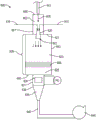
FIG. 2 schematically depicts an apparatus for depositing inorganic material according to embodiments disclosed herein;
FIG. 3 schematically depicts an apparatus for depositing inorganic material according to embodiments disclosed herein;
FIG. 4 schematically depicts an apparatus for depositing inorganic material according to embodiments disclosed herein;
FIG. 5 schematically depicts an apparatus for depositing inorganic material according to embodiments disclosed herein;
FIG. 6 schematically depicts an apparatus for depositing inorganic material according to embodiments disclosed herein;
FIG. 7 schematically depicts an unplugged honeycomb body;
FIG. 8 schematically depicts a wall-flow particulate filter, according to embodiments disclosed and described herein;
FIG. 9 is a cross-sectional longitudinal view of the particulate filter shown in FIG. 8;
FIG. 10 schematically depicts walls of a honeycomb body having a particulate loading;
FIG. 11 is a flow chart depicting one exemplary embodiment of a water-based process of forming a material in accordance with embodiments disclosed herein;
FIG. 12 is a graph illustrating filtration efficiency before and after curing for various samples prepared according to embodiments disclosed herein;
FIG. 13 is a graph showing pressure drop before and after curing for various samples prepared according to embodiments disclosed herein;
FIG. 14A is an SEM photograph showing alumina agglomerates resulting from an ethanol-based suspension (DK-2405-5%);
FIG. 14B is an SEM photograph showing alumina agglomerates resulting from a water-based suspension (ALLIED-880-20%);
FIG. 14C is an SEM photograph showing alumina agglomerates resulting from an aqueous based suspension (DK-880-20%);
FIG. 14D is an SEM photograph showing alumina agglomerates resulting from an aqueous based suspension (DK-880-50%);
FIG. 14E is an SEM photograph showing alumina agglomerates resulting from a water-based suspension (DK-9950-50%);
FIG. 14F is an SEM photograph showing alumina agglomerates resulting from a water-based suspension (DK-2404-20%);
FIG. 15A is a graph showing FE/dP performance for a water-based process and an ethanol-based process for various samples prepared according to embodiments disclosed herein;
fig. 15B is a graph showing FE versus deposition load for water-based and ethanol-based processes for various samples prepared according to embodiments disclosed herein;
FIG. 16A is an SEM photograph showing alumina agglomerates produced from an ethanol-based suspension;
FIG. 16B is an SEM photograph showing alumina agglomerates produced from an aqueous-based suspension and deposited on a porous ceramic wall;
FIG. 16C is a graph showing particle size of agglomerates for agglomerates produced by an ethanol-based process and a water-based process;
FIG. 16D is a graph illustrating the cumulative particle size distribution of agglomerates resulting from ethanol-based processes and water-based processes;
FIG. 17A is a graph illustrating the effect of different heat treatment temperatures on the durability of filtration efficiency (in terms of water resistance) for samples prepared according to embodiments disclosed herein;
FIG. 17B is a graph illustrating the effect of different heat treatment temperatures on pressure drop (in terms of water resistance) for samples prepared according to embodiments disclosed herein;
FIG. 18A is a graph illustrating the effect of heat treatment on filtration efficiency (in terms of water resistance) at different heat treatment temperatures for samples prepared according to embodiments disclosed herein;
FIG. 18B is a graph illustrating the effect of heat treatment on pressure drop at different heat treatment temperatures for samples prepared according to embodiments disclosed herein;
FIG. 19 is a graph showing filtration efficiency after various durability tests including a high flow test, a cold shake test, a vehicle test, and a two-stage water resistance test;
fig. 20 is an SEM photograph of a top view of the inlet region of inlet channels of a plugged honeycomb body made according to embodiments disclosed herein;
fig. 21 is an SEM photograph of a cross-sectional side view of an inlet region of an inlet channel of a plugged honeycomb body made according to embodiments disclosed herein;
Fig. 22 is an SEM photograph of a top view of a central region of inlet channels of a plugged honeycomb body made according to embodiments disclosed herein;
fig. 23 is an SEM photograph of a cross-sectional side view of a middle region of inlet channels of a plugged honeycomb body made according to embodiments disclosed herein;
fig. 24 is an SEM photograph of a top view of an outlet region of inlet channels of a plugged honeycomb body made according to embodiments disclosed herein;
fig. 25 is an SEM photograph of a cross-sectional side view of an outlet region of inlet channels of a plugged honeycomb body made according to embodiments disclosed herein;
fig. 26 is an SEM photograph of an enlarged cross-sectional side view of an outlet region of inlet channels of a plugged honeycomb body made according to embodiments disclosed herein;
FIG. 27 is a SEM photograph of FIG. 26 with color reversed;
FIG. 28 is a portion of the SEM photograph of FIG. 27 with the dashed line surrounding the aggregate 1500;
FIG. 29 is a schematic illustration of agglomerates 1502 forming a region of the aggregate 1500 outlined by the dashed lines of FIG. 28A;
FIG. 30 is a flowchart illustrating an exemplary process flow according to one specific embodiment;
fig. 31A schematically depicts an apparatus for depositing filter material according to embodiments disclosed herein;
Fig. 31B schematically depicts an apparatus for depositing filter material according to embodiments disclosed herein;
fig. 31C schematically depicts an apparatus for depositing filter material according to embodiments disclosed herein;
fig. 31D schematically depicts an apparatus for depositing filter material according to embodiments disclosed herein;
FIG. 32 is Al according to embodiments disclosed and described herein2O3SEM magnified photographs of aggregates or agglomerates;
FIG. 33A is a top view SEM photograph of walls of a honeycomb body comprising discrete regions of filter material deposits formed on the walls at an axial distance of 10% from the inlet end of the honeycomb body;
FIG. 33B is a top view SEM photograph of walls of a honeycomb body comprising discrete regions of filter material deposits formed on the walls at an axial distance of 50% from the inlet end of the honeycomb body;
FIG. 33C is a top view SEM photograph of walls of a honeycomb body comprising deposits of filter material formed on the walls at an axial distance of 90% from the inlet end of the honeycomb body;
FIG. 33D is an enlarged side view SEM of a cross-section of a wall of a honeycomb body showing filter material deposits at an axial distance of 10% from the inlet end of the honeycomb body;
FIG. 33E is an enlarged side view SEM of a cross-section of a wall of a honeycomb body showing a deposit of filter material at an axial distance of 50% from the inlet end of the honeycomb body;
FIG. 33F is an enlarged side view SEM of a cross-section of a wall of a honeycomb body showing filter material deposits at an axial distance of 90% from the inlet end of the honeycomb body;
FIG. 34 is a graph comparing filtration efficiency versus soot loading for a "blank" honeycomb without filter material deposits and a honeycomb comprising alumina filter material deposits, according to embodiments disclosed and described herein;
FIG. 35 is a graphical representation comparing "clean" backpressure (no soot or soot loading) versus honeycomb flow rate for a "blank" honeycomb without filter material deposits and two different honeycombs containing alumina filter material deposits according to embodiments disclosed and described herein;
FIG. 36 is a graphical representation comparing backpressure versus soot load for a "blank" honeycomb without filter material deposits and a honeycomb comprising alumina filter material deposits, according to embodiments disclosed and described herein;
FIG. 37A is a top view SEM photograph of walls of a honeycomb body comprising discrete regions of filter material deposits formed on the walls at an axial distance of 50% from the inlet end of the honeycomb body;
FIG. 37B is a top view SEM photograph of walls of a honeycomb body comprising discrete regions of filter material deposits formed on the walls at an axial distance of 50% from the inlet end of the honeycomb body;
FIG. 37C is a top view SEM of walls of a honeycomb comprising discrete regions of deposits of filter material formed on the walls at an axial distance of 90% from the inlet end of the honeycomb;
FIG. 37D is a top view SEM photograph of walls of a honeycomb body comprising discrete regions of filter material deposits formed on the walls at an axial distance of 10% from the inlet end of the honeycomb body;
FIG. 37E is a top view SEM photograph of walls of a honeycomb body comprising discrete regions of filter material deposits formed on the walls at an axial distance of 50% from the inlet end of the honeycomb body;
FIG. 37F is a top view SEM photograph of walls of a honeycomb body comprising discrete regions of filter material deposits formed on the walls at an axial distance of 90% from the inlet end of the honeycomb body;
FIG. 38A is a top view SEM photograph of walls of a honeycomb body comprising discrete regions of filter material deposits formed on the walls at an axial distance of 10% from the inlet end of the honeycomb body;
FIG. 38B is a top view SEM photograph of walls of a honeycomb body comprising discrete regions of filter material deposits formed on the walls at an axial distance of 50% from the inlet end of the honeycomb body;
FIG. 38C is a top view SEM photograph of walls of a honeycomb body comprising discrete regions of filter material deposits formed on the walls at an axial distance of 90% from the inlet end of the honeycomb body;
FIG. 39 is an annotated magnified SEM photograph of an exemplary primary particle used to measure roundness;
FIG. 40 is an annotated SEM photograph of exemplary agglomerates for measuring roundness;
FIG. 41 is a graph showing the effect of percent binder on smoke filtration efficiency reduction after exposure to a basic water spray test;
FIG. 42 shows an SEM of alumina particles used to make a suspension according to an embodiment of the present disclosure;
fig. 43A is an SEM photograph showing alumina agglomerates resulting from a suspension including 5% binder, in accordance with an embodiment of the present disclosure;
fig. 43B is an SEM photograph showing alumina agglomerates resulting from a suspension including 15% binder, in accordance with an embodiment of the present disclosure;
FIG. 44 is a graph of smoke filtration efficiency versus pressure drop for samples prepared according to an embodiment of the present disclosure;
Fig. 45A is an SEM photograph showing alumina agglomerates on the wall surface of a wall flow filter resulting from a suspension with 5% binder at a depth of 50% from the inlet prior to water contact;
fig. 45B is an SEM photograph showing alumina agglomerates produced from a suspension with 5% binder on the wall surface of a wall flow filter at a depth of 50% from the inlet after water contact;
fig. 46A is an SEM photograph showing alumina agglomerates on the wall surface of a wall flow filter resulting from a suspension with 15% binder at a depth of 50% from the inlet prior to water contact;
fig. 46B is an SEM photograph showing alumina agglomerates produced from a suspension with 15% binder on the wall surface of a wall flow filter at a depth of 50% from the inlet after water contact;
FIG. 47 is a graph of clean filtration efficiency versus soot loading for a sample after exposure of the sample to water;
FIG. 48 is a graph showing the loss of clean filtration efficiency after exposure of the sample to water;
FIG. 49 is a graph of filtration efficiency versus soot load after exposure of a sample to water;
FIG. 50 is a graph of filtration efficiency versus soot load after exposure of a sample to water;
FIG. 51 is a graph showing the loss of filtration efficiency after exposure of a sample to water;
FIG. 52 is a graph of smoke FE versus pressure drop (Pa) at 1.7m/s for various slurry compositions;
FIG. 53 is a graph of load (g/L) versus pressure drop (Pa) at 1.7m/s for different slurry compositions;
FIG. 54 is a graph of efficiency versus deposition time (seconds) for different slurry compositions;
figures 55A-55C provide SEM images of spray dried siloxane-alumina agglomerates with 1 wt% PEG-PPG-PEG dispersant in the slurry;
figures 56A-56C provide SEM images of spray dried siloxane-alumina agglomerates with 3 wt% PEG-PPG-PEG dispersant in the slurry;
FIGS. 57-60 provide SEM images of cross-sectional views of unmilled A1000SGD agglomerates using different dispersants; and is
Figures 61A-61B, 62A-62B, and 63A-63B provide SEM images of spray dried siloxane-alumina agglomerates utilizing a combination of PEG-PPG-PEG dispersant (1.5 wt% in the slurry) and TEA (1.5 wt% in the slurry), and SEM images of spray dried agglomerates having only 1 wt% and 3 wt% PEG-PPG-PEG dispersant in the slurry.
Detailed Description
Reference will now be made in detail to embodiments of methods for forming honeycomb bodies, including porous honeycomb bodies, including inorganic deposits (or "filter deposits") in and/or on the porous ceramic walls of the honeycomb matrix, embodiments of which are illustrated in the accompanying drawings. Filter deposits include materials deposited into the honeycomb body, as well as compounds that may be formed from the originally deposited material or materials by, for example, heating. For example, the binder material may be converted by heating to an organic component that is ultimately burned off or volatilized, while the inorganic component (e.g., silica) remains contained within the honeycomb filter body. Wherever possible, the same reference numbers will be used throughout the drawings to refer to the same or like parts.
Definition of
As used in this specification and the appended claims, the singular forms "a", "an", and "the" include embodiments having plural referents, unless the context clearly dictates otherwise. As used in this specification and the appended claims, the term "or" is generally employed in its sense including "and/or" unless the context clearly dictates otherwise.
As used herein, "having," containing, "" including, "" containing, "and the like are used in their open-ended sense, and typically mean" including, but not limited to.
As used herein, a "honeycomb" comprises a ceramic honeycomb structure having a matrix of intersecting walls that form cells that define channels. The ceramic honeycomb structure may be formed, extruded or molded from plasticized ceramics or ceramic-forming batch mixtures or pastes. The honeycomb body may include an outer peripheral wall or skin that is extruded with the matrix of walls or applied after the matrix is extruded. For example, the honeycomb body may be a plugged ceramic honeycomb structure that forms a filter body comprising cordierite or other suitable ceramic material. The plugged honeycomb body has one or more channels plugged at one or both ends of the honeycomb body.
Disclosed herein are honeycombs including a ceramic honeycomb structure including at least one wall carrying one or more deposits of filter material configured to filter particulate matter in a gas stream. The deposits of filter material may be in discrete regions, or in some portions or embodiments, may form one or more layers of filter material at given locations on the walls of the honeycomb body. The filter material deposit preferably comprises an inorganic material, in some embodiments an organic material, and in some embodiments both an inorganic material and an organic material. For example, in one or more embodiments, the honeycomb body may be formed from cordierite or other porous ceramic materials, and further include a deposit of inorganic material disposed on or below the wall surfaces of the cordierite honeycomb structure.
In some embodiments, the filter material comprises one or more inorganic materials, for example, one or more ceramic or refractory materials.
As used herein, "green" or "green ceramic" are used interchangeably and refer to unsintered or unfired materials unless otherwise specified.
Method
Aspects of the present disclosure relate to methods of forming porous bodies, e.g., porous ceramic honeycomb bodies, comprising materials such as filter materials, e.g., inorganic materials, e.g., ceramics or refractory materials, or even porous ceramics or refractory materials. In a particular embodiment, the filter material is an aerosol deposited filter material. In some preferred embodiments, the filter material comprises a plurality of agglomerates of inorganic particles, wherein the agglomerates comprise an inorganic material, such as a ceramic or refractory material. In some embodiments, the agglomerates are porous, which may allow gas to flow through the agglomerates.
Aerosol deposition enables deposition of filter material onto the porous ceramic walls, which may be as small as discrete regions of individual agglomerates or larger regions, such as a plurality of agglomerates, in some embodiments in the form of a porous layer of filter material on and/or in at least some surfaces of the walls of the ceramic honeycomb body. In certain embodiments, an aerosol deposition process according to one or more embodiments is advantageous in that ceramic honeycomb bodies having enhanced filtration properties can be economically and/or more efficiently produced.
In certain embodiments, the aerosol deposition process disclosed herein comprises: the method includes the steps of preparing a mixture (e.g., inorganic material, liquid vehicle, and binder), atomizing the mixture through a nozzle using an atomizing gas to form agglomerates and/or aggregates comprising the inorganic material, liquid vehicle, and binder (if any), drying the agglomerates and/or aggregates in the presence of a carrier gas or gaseous carrier stream, depositing the aggregates and/or agglomerates onto a honeycomb body, and optionally curing the material. In some embodiments, the walls of the apparatus may be heated to help dry the aggregates and/or agglomerates.
In various embodiments, in addition to or in lieu of the walls of the heating apparatus, the carrier gas may be heated such that the liquid carrier may evaporate more quickly from the agglomerates, which in turn allows for more efficient production of the agglomerates. The heated gaseous carrier stream carries the atomized droplets and formed agglomerates through the apparatus and into the honeycomb body. In some embodiments, the atomizing gas is heated separately or in combination with the heating of the carrier gas. In some embodiments, co-flowing aerosolized droplets and/or agglomerates with a gaseous carrier stream in substantially the same direction into a chamber of an apparatus may help to reduce material loss or excessive spraying on the walls of the apparatus. Additionally, a converging section may be added to the apparatus prior to the agglomerates entering the ceramic honeycomb body to help the gas flow and particles more uniformly through the apparatus. The inner diameter of the end of the converging section may be slightly larger than the outer diameter of the ceramic honeycomb body to reduce or eliminate the boundary effect of non-uniform particle deposition.
In an atomizing nozzle or atomizer, a suspension comprising a mixture of a liquid carrier, a binder, and solid particles can be broken up into small droplets, e.g., droplets having an average droplet size of 4-6 microns, using a high pressure and/or high velocity atomizing gas. Heating these droplets and rapidly evaporating the liquid vehicle forms porous inorganic agglomerates that are subsequently deposited as porous inorganic features or structures onto the honeycomb walls. In some embodiments, more than one nozzle is used, even in some cases, under the same operating conditions, to reduce the liquid flow through each nozzle and to allow smaller droplet sizes.
In accordance with one or more embodiments, disclosed herein is a method that includes forming an aerosol with a binder, which is deposited on a honeycomb body to provide a high filtration efficiency material that may be present as discrete regions on the honeycomb body and/or, in some portions or embodiments, as an inorganic layer to provide a particulate filter. According to one or more embodiments, the performance is > 90% filtration efficiency compared to a blank filter, with a pressure drop loss of < 10%. According to one or more embodiments, as shown in FIG. 1, method 400 includes the steps of: mixture preparation 405, atomization to form droplets 410, mixed droplets and a gaseous carrier stream 415; evaporating the liquid carrier to form agglomerates 420, depositing material (e.g., agglomerates) on the walls of the wall flow filter 425, and optionally post-treating 430, for example, to incorporate the material on and/or in the porous walls of the honeycomb. The aerosol deposition process forming agglomerates comprising the binder may provide high mechanical integrity even without any high temperature curing step (e.g., heating to a temperature in excess of 1000 ℃), and in some embodiments may provide even greater mechanical integrity after a curing step, e.g., a high temperature (e.g., heating to a temperature in excess of 1000 ℃) curing step. In the method of fig. 1, the aerosol deposition forms a deposit of inorganic material, which in some embodiments is a deposit of porous material. In some embodiments, the material deposit is in the form of discrete regions of filter material. In some embodiments, at least some portion of the material deposit may be in the form of a porous inorganic layer.
In various embodiments, the method further comprises component switching to semi-continuously or continuously deposit the agglomerates onto the porous walls of the plugged honeycomb body, which reduces the idle time of the apparatus. In one or more embodiments, the component switching is timed to be deposited substantially continuously into and/or onto the plurality of ceramic honeycomb bodies. By continuous is meant that the operating equipment is maintained at operating temperature and pressure and the feed stream is flowing down, and the flow of gaseous carrier stream and agglomerates into the component (e.g., wall-flow filter) is only interrupted in order to switch the loaded component to an unloaded component. Semicontinuous also allows for small interruptions in the feed supply stream and allows for adjustment of operating temperature and pressure. In one or more embodiments, a semi-continuous stream means that the stream is interrupted for greater than or equal to 0.1% to less than or equal to 5% of the duration of the operation, including greater than or equal to 0.5%, greater than or equal to 1%, greater than or equal to 1.5%, greater than or equal to 2%, greater than or equal to 2.5%, and/or less than or equal to 4.5%, less than or equal to 4%, less than or equal to 3.5%, less than or equal to 3% of the duration of the operation. In one or more embodiments, the stream is continuous for an operating duration of greater than or equal to 95% to less than or equal to 100%, including an operating duration of greater than or equal to 96%, greater than or equal to 97%, greater than or equal to 98%, greater than or equal to 99%, greater than or equal to 99.5%, and/or less than or equal to 99.9%, less than or equal to 99%, less than or equal to 98%, less than or equal to 97%.
Preparation of the mixture 405: in forming the inorganic material for deposition, commercially available inorganic particles may be used as the starting material in the mixture. According to one or more embodiments, the particles are selected from Al2O3、SiO2、TiO2、CeO2、ZrO2SiC, MgO and combinations thereof. In one or more embodiments, the mixture is a suspension. The particles may be supplied as a feedstock suspended in a liquid carrier, to which additional liquid carrier is optionally added.
In some embodiments, the liquid carrier is an alcohol (e.g., ethanol). In other embodiments, the liquid is water. Thus, in some embodiments, the mixture is water-based; for example, the liquid carrier of the suspension may be water. In other embodiments, the mixture is organic based; for example, the liquid carrier of the mixture can be an alcohol, e.g., ethanol or methanol, or a combination thereof. In one or more embodiments, the vapor pressure of the liquid carrier is greater than the vapor pressure of water at the temperature of the gaseous carrier stream. In one or more embodiments, the liquid carrier consists essentially of a material having a boiling point lower than the boiling point of water at the temperature of the gaseous carrier stream. In one or more embodiments, the liquid carrier is an alcohol. In one or more embodiments, the liquid carrier is methoxyethanol, ethanol, xylene, methanol, ethyl acetate, benzene, or mixtures thereof. In one or more embodiments, the liquid carrier is an alcohol. In one or more embodiments, the liquid carrier consists essentially of water.
In some embodiments, the suspension comprises, by weight: 5-20% particles and 80-95% liquid, and all values and subranges therebetween. In one embodiment, the suspension comprises, by weight: 11% + -1% alumina and 89% + -1% ethanol.
In one or more embodiments, the average primary particle size of the particles is in the following range: from about 10nm to about 4 μm, from about 20nm to about 3 μm, or from about 50nm to about 2 μm, or from about 50nm to about 900nm, or from about 50nm to about 600 nm. In particular embodiments, the average primary particle size is in the range of about 100nm to about 200nm, for example, 150 nm. The average primary particle size may be determined as a calculated value derived from the BET surface area of the aerosol particles, which in some embodiments is currently 10m2/g。
In one or more embodiments, the primary particles comprise ceramic particles, e.g., oxide particles, e.g., Al2O3、SiO2、MgO、CeO2、ZrO2、CaO、TiO2Cordierite, mullite, SiC, aluminum titanate and mixtures thereof.
A solvent is used to form a mixture, which is added to dilute the suspension, if necessary. Reducing the solids content of the mixture can proportionally reduce the aggregate size if the droplets produced by atomization are of similar size. The solvent should be miscible with the suspension mentioned above and should be a solvent for the binder and other ingredients.
Optionally, a binder is added to strengthen the agglomerates and preferably provide tack or tackiness, and the binder may include an inorganic binder to provide mechanical integrity to the deposited material. At a high temperature (>At 500 deg.C, the binder may provide bond strength between the particles. The starting material may be organic. Upon exposure to elevated temperatures in excess of about 150 ℃, the organic starting materials will decompose or react with moisture and oxygen in the air, and the final deposited material composition may comprise Al2O3、SiO2、MgO、CeO2、ZrO2、CaO、TiO2Cordierite, mullite, SiC, aluminum titanate and mixtures thereof. An example of a suitable binder is DowsilTMUS-CF-2405 and DowsilTMU.S. Pat. No. 5,2403, all of which are available from The Dow Chemical Company. Exemplary binder contents are particle contents of greater than or equal to 5 wt% to less than or equal to 25 wt%. In one embodiment, the binder content is 15% to 20% ± 1% by weight.
A catalyst may be added to accelerate the curing reaction of the binder. For accelerating DowsilTMAn exemplary catalyst for the curing reaction of US-CF-2405 is titanium butoxide. An exemplary catalyst content is 1 wt% of the binder.
Agitation of the mixture or suspension may be performed during storage and/or waiting for delivery to the nozzle by using desired agitation techniques. In one or more embodiments, the agitation is performed by a mechanical stirrer. In one embodiment, the use of a mechanical stirrer facilitates reducing and/or eliminating potential contamination from plastic-coated mixing bars that come into contact with a holding container for a magnetic stirring system.
Atomization to form droplets 410: the mixture is atomized into small droplets by passing a high pressure gas through a nozzle. An example of a nozzle is 1/4J-SS + SU11-SS from Spraying Systems Co. The arrangement includes a nozzle body along with a fluid cap 2050 and an air cap 67147. The atomizing gas may facilitate breaking up the liquid-particle-binder stream into droplets.
In one or more embodiments, the nozzles herein are nozzles that utilize internal mixing, e.g., the internal mixing nozzles with part numbers given above. In one or more embodiments, the nozzles herein are nozzles that utilize external mixing, for example, the external mixing nozzle arrangement of Spraying Systems (Spraying Systems): 1/4J-SS + SU1A, consisting of a 64 air cap and a 1650 fluid cap. Another useful arrangement consists of a 64 air cap and a 1250 fluid cap. The external mixing nozzle may advantageously allow for smaller particle sizes and a tighter particle size distribution, which improves material utilization and filtration efficiency. The outer mixing nozzle often tends to have less clogging than the inner mixing nozzle. In one or more embodiments, the nozzle herein is a converging nozzle. A converging nozzle as used herein refers to a nozzle having a fluid flow passage that decreases in cross-sectional area from an inlet to an outlet, thereby accelerating the flow of fluid. The converging nozzle may be internally or externally mixed.
In one or more embodiments, the liquid-particle-binder droplets are directed into the chamber through a nozzle.
In one or more embodiments, the liquid-particle-binder droplets are directed into the chamber through a plurality of nozzles. In one or more embodiments, atomization of multiple liquid-particle-binder streams occurs using multiple atomizing nozzles. The plurality of nozzles can include 2 or more nozzles, 3 or more, 4 or more, 5 or more, 6 or more, 7 or more, 8 or more, 9 or more, 10 or more nozzles, and the like. The plurality of nozzles may be evenly spaced within the chamber. In one or more embodiments, each nozzle of the plurality of nozzles is angled toward a center of the apparatus. The angle of the nozzle may be acute with respect to the sidewall of the apparatus, ranging from less than 90 ° to greater than 10 °, and all values and subranges therebetween, including 20 ° to 45 °.
The pressure of the atomizing gas may be in the range of 20psi to 150 psi. The pressure of the liquid may be in the range of 1psi to 100 psi. According to one or more embodiments, the average droplet size may be in the range of 1 μm to 40 μm, for example included in the following ranges: greater than or equal to 1 μm to less than or equal to 15 μm; greater than or equal to 2 μm to less than or equal to 8 μm; greater than or equal to 4 μm to less than or equal to 8 μm; and greater than or equal to 4 μm to less than or equal to 6 μm; and all values and subranges therebetween. The droplet size can be adjusted by adjusting the surface tension of the mixture, the viscosity of the mixture, the density of the mixture, the gas flow rate, the gas pressure, the liquid flow rate, the liquid pressure, and the nozzle design. In one or more embodiments, the atomizing gas comprises nitrogen. In one or more embodiments, the atomizing gas can consist essentially of an inert gas. In one or more embodiments, the atomizing gas can be primarily one or more inert gases. In one or more embodiments, the atomizing gas can be primarily nitrogen. In one or more embodiments, the atomizing gas can be primarily air. In one or more embodiments, the atomizing gas can consist essentially of nitrogen or air. In one or more embodiments, the atomizing gas can be dry. In one or more embodiments, the atomizing gas may comprise substantially no liquid carrier upon entering the chamber.
In some embodiments, the suspension flow rate is in the range of 10 g/min to 25 g/min, including all values and subranges therebetween, including 18 g/min.
In some embodiments, the atomizing gas flow rate (nitrogen flow rate) is in the range of 2 to 10Nm3In the range of/hour, including all values and subranges therebetween, including from 5 to 6Nm3In terms of hours.
The suspension flow and the corresponding agglomerate size can be controlled by means of a pressure control system or a flow control system to suit the apparatus. For pressure control systems, the pressure controller is in communication with a delivery conduit (e.g., a pipe (tubing) or tubing), and a suspension of primary particles in a liquid is introduced into the delivery conduit and then flows to the nozzle. For a flow control system, a syringe pump is provided which delivers a suspension of primary particles in a liquid to a nozzle. The atomizing gas is typically supplied separately to the nozzle. In a preferred embodiment, the pump directs the liquid-particle-binder mixture to the atomizing nozzle at a substantially constant flow rate. A constant flow rate may be advantageous as opposed to maintaining a constant pressure, as a constant flow rate may help reduce particle size variation, thereby improving material utilization.
In one or more embodiments, a suspension comprising an inorganic material, a liquid vehicle, and in some embodiments a binder, is supplied to the nozzle as a liquid-particle-binder stream. That is, particles of the inorganic material may be mixed with the liquid vehicle and the binder material to form a liquid-particulate-binder stream. The liquid-particle-binder stream is atomized by an atomizing gas through a nozzle into liquid-particle-binder droplets. In one or more embodiments, the liquid-particle-binder stream is mixed with an atomizing gas. In one or more embodiments, a stream of liquid-particle-binder is directed into an atomizing nozzle to atomize the particles into liquid-particle-binder droplets. The liquid-particle-binder droplet includes a liquid vehicle, a binder material, and particles.
In one or more embodiments, the liquid-particle-binder stream is mixed with the atomizing gas via an atomizing nozzle. In one or more embodiments, the liquid-particle-binder stream enters an atomizing nozzle. In one or more embodiments, the mixing of the liquid-particle-binder stream with the atomizing gas occurs within the atomizing nozzle. In one or more embodiments, the mixing of the liquid-particle-binder stream with the atomizing gas occurs outside of the atomizing nozzle.
Mixing 415 of the liquid droplets and the gaseous carrier stream: the droplets are conveyed towards the honeycomb body by the stream of gaseous carrier. In one or more embodiments, the gaseous carrier stream includes a carrier gas and an atomizing gas. In one or more embodiments, at least a portion of the carrier gas contacts the atomizing nozzle. In one or more embodiments, substantially all of the liquid vehicle is evaporated from the droplets to form agglomerates comprising the particles and the binder material.
In one or more embodiments, the gaseous carrier stream is heated prior to mixing with the liquid droplets. In one or more embodiments, the gaseous carrier stream is at a temperature of greater than or equal to 50 ℃ to less than or equal to 500 ℃, including all temperatures of: greater than or equal to 80 ℃ to less than or equal to 300 ℃, greater than or equal to 50 ℃ to less than or equal to 150 ℃, and all values and subranges therebetween. In operation, the temperature may be selected to evaporate at least the solvent of the mixture or suspension, as long as the final temperature is above the dew point. By way of non-limiting example, ethanol may be vaporized at low temperatures. Without being bound by theory, it is believed that the advantage of higher temperatures is that the droplets evaporate more quickly and when the liquid is evaporated in large quantities, the droplets are less likely to stick upon collision. In certain embodiments, smaller agglomerates promote better filter material deposit formation. In addition, it is believed that if the droplets collide but contain only a small amount of liquid (e.g., only inside), the droplets may not coalesce into a spherical shape. In some embodiments, non-spherical agglomerates can provide desirable filtration performance.
In one or more embodiments, the atomizing gas is heated to form a heated atomizing gas, which is then flowed through and/or contacted with the nozzle. In one or more embodiments, the heated atomizing gas is at a temperature of greater than or equal to 50 ℃ to less than or equal to 500 ℃, including all temperatures of: greater than or equal to 80 ℃ to less than or equal to 300 ℃, greater than or equal to 50 ℃ to less than or equal to 150 ℃, and all values and subranges therebetween.
In one or more embodiments, both the carrier gas and the atomizing gas are heated independently and brought into contact with the nozzle. In one or more embodiments, the gaseous stream is heated, but the atomizing gas and nozzle are maintained at a low temperature (about equal to room temperature, e.g., 25-40 ℃). In one or more embodiments, the atomizing nozzle is cooled during atomization. In one or more embodiments, the temperature of the atomizing nozzle is maintained below the boiling point of the liquid carrier.
A carrier gas is provided to the apparatus to facilitate drying, and the liquid-particle-binder droplets and resulting agglomerates are carried through the apparatus and into the honeycomb body. In one or more embodiments, the carrier gas is primarily an inert gas, such as nitrogen, which is particularly advantageous for alcohol-based liquid carriers and droplets. In one or more embodiments, the carrier gas consists essentially of an inert gas. In one or more embodiments, the carrier gas is primarily one or more inert gases. In one or more embodiments, the carrier gas is primarily nitrogen. In one or more embodiments, the carrier gas is primarily air. In one or more embodiments, the carrier gas consists essentially of nitrogen or air. In one or more embodiments, the carrier gas is dry. In one or more embodiments, the carrier gas comprises substantially no liquid carrier upon entering the chamber. In one or more embodiments, the carrier gas comprises less than 5 wt% water vapor. In one or more embodiments, the carrier gas is heated prior to mixing with the droplets. In one or more embodiments, the carrier gas is at a temperature of greater than or equal to 50 ℃ to less than or equal to 500 ℃, including all temperatures of: greater than or equal to 80 ℃ to less than or equal to 300 ℃, greater than or equal to 50 ℃ to less than or equal to 150 ℃, and all values and subranges therebetween.
In one or more embodiments, the atomizing gas and carrier gas are independently delivered to the apparatus at a pressure of greater than or equal to 90psi, including greater than or equal to 95psi, greater than or equal to 100psi, greater than or equal to 105psi, greater than or equal to 100psi, greater than or equal to 115psi, or greater than or equal to 120 psi. In one or more embodiments, the booster provides the atomizing gas and carrier gas at the desired pressures.
The apparatus may include a diffusion region downstream of the nozzle. At least some mixing of the gaseous carrier stream with the liquid-particle-binder droplets occurs in the diffusion zone.
When the gaseous carrier stream is mixed with the liquid-particle-binder droplets in the chamber, a gas-liquid-particle-binder mixture is formed. The gas-liquid-particle-binder mixture is heated at a mixing zone. In one or more embodiments, droplets containing particles and binder are present during mixing. In one or more embodiments, the gaseous carrier stream is heated prior to mixing with the liquid-particle-binder droplets.
In one embodiment, the carrier gas is delivered to the chamber as an annular co-flow around the nozzle. In one embodiment, the carrier gas is delivered to the chamber of the conduit in a circular flow around the nozzle, in a co-flow around the droplets at the end of the nozzle.
Evaporation to form agglomerates 420: the capillary force influence of the liquid may form inhomogeneous materials, which may lead toResulting in high pressure drop losses, in order to avoid liquid capillary forces effects, the droplets are dried in the evaporation section of the apparatus, forming dry solid agglomerates, which may be referred to as secondary particles, or "microparticles", consisting of primary nanoparticles and binder-type materials. The liquid carrier or solvent is evaporated and passed through the honeycomb in a gas or vapor phase to minimize liquid solvent residue or condensation during material deposition. When the agglomerates are carried into the honeycomb body by the gas stream, the residual liquid in the inorganic material should be less than 10 wt.%. All liquids are preferably evaporated by drying and converted to a gas or vapour phase. The liquid residue may include solvent in the mixture (e.g., ethanol in embodiments), or water condensed from the gas phase. The binder is not considered to be a liquid residue even though some or all of the binder may be in a liquid or other non-solid state prior to curing. In one or more embodiments, the total volumetric flow rate through the chamber is greater than or equal to 5Nm3Per hour and/or less than or equal to 200Nm 3Hour/hour; including greater than or equal to 20Nm3Per hour and/or less than or equal to 100Nm3Hour/hour; and all values and subranges therebetween. Higher flow rates may deposit more material than lower flow rates. Higher flow rates may be useful when filters of larger cross-sectional area are to be produced. Filters of larger cross-sectional area may be used in filtration systems for architectural or outdoor filtration systems.
In one or more embodiments, substantially all of the liquid carrier is evaporated from the droplets to form agglomerates of particles and binder material, the agglomerates being dispersed in the gaseous carrier stream. In one or more embodiments, the apparatus has an evaporation section having an axial length sufficient to evaporate at least a portion of the liquid carrier, including most and/or all of the liquid carrier, from the agglomerates.
With respect to flow, in one embodiment, the path of the droplets and the path of the gaseous carrier stream are substantially perpendicular prior to entering the evaporation section. In one or more embodiments, the carrier gas contacts the atomizing nozzle through a first path, and wherein the path of the droplets and a second path of the carrier gas are substantially perpendicular to each other before entering the evaporation section of the conduit.
In another embodiment, the path of the droplets and the path of the gaseous carrier stream are substantially parallel after entering the evaporation section. In one or more embodiments, the path of the droplets and the path of the gaseous carrier stream are substantially parallel to each other after entering the evaporation section of the conduit. In one or more embodiments, the path of the droplets and the path of the carrier gas are substantially parallel to each other after entering the evaporation section of the conduit.
In one embodiment, the gaseous carrier stream exits the chamber in a direction substantially parallel to gravity. In one embodiment, the gaseous carrier stream exits the chamber in a substantially downward direction. In one embodiment, the gaseous carrier stream exits the chamber in a substantially upward direction.
Depositing 425 in the honeycomb body: secondary particles or agglomerates of primary particles are carried in the gas stream and as the gas passes through the honeycomb, the secondary particles or agglomerates, and/or aggregates thereof, are deposited on the inlet wall surfaces of the honeycomb. In one or more embodiments, the agglomerates and/or aggregates thereof are deposited onto the porous walls of the plugged honeycomb. The deposited agglomerates may be disposed on, in, or both the porous walls. In one or more embodiments, a plugged honeycomb body includes inlet channels that are plugged at a distal end of the honeycomb body and outlet channels that are plugged at a proximal end of the honeycomb body. In one or more embodiments, the agglomerates and/or aggregates thereof are deposited on, in, or both the walls defining the inlet passage.
The flow may be driven by a fan, blower or vacuum pump. Additional air may be drawn into the system to achieve the desired flow rate. A desired flow rate of 5 to 200m3In the range of/hour.
An exemplary honeycomb body is suitable for use as a Gasoline Particulate Filter (GPF) and has the following non-limiting characteristics: 4.055 inches (10.3cm) in diameter, 5.47 inches (13.9cm) in length, 200 cell Channels Per Square Inch (CPSI), 8 mils (203 μm) wall thickness, and 14 μm average pore size.
In one or more embodiments, the average diameter of the secondary particles or agglomerates is within the following range: 300nm to 10 μm, 300nm to 8 μm, 300nm to 7 μm, 300nm to 6 μm, 300nm to 5 μm, 300nm to 4 μm, or 300nm to 3 μm. In particular embodiments, the secondary particles or agglomerates have an average diameter in the range of 1.5 μm to 3 μm, including about 2 μm. The average diameter of the secondary particles or agglomerates can be measured by scanning electron microscopy.
In one or more embodiments, the average diameter of the secondary particles or agglomerates is within the following range: 300nm to 10 μm, 300nm to 8 μm, 300nm to 7 μm, 300nm to 6 μm, 300nm to 5 μm, 300nm to 4 μm, or 300nm to 3 μm, including the range of 1.5 μm to 3 μm, and including about 2 μm, and the ratio of the average diameter of the secondary particles or agglomerates to the average diameter of the primary particles is in the following range: about 2:1 to about 67: 1; about 2:1 to about 9: 1; about 2:1 to about 8: 1; about 2:1 to about 7: 1; about 2:1 to about 6: 1; about 2:1 to about 5: 1; about 3:1 to about 10: 1; about 3:1 to about 9: 1; about 3:1 to about 8: 1; about 3:1 to about 7: 1; about 3:1 to about 6: 1; about 3:1 to about 5: 1; about 4:1 to about 10: 1; about 4:1 to about 9: 1; about 4:1 to about 8: 1; about 4:1 to about 7: 1; about 4:1 to about 6: 1; about 4:1 to about 5: 1; about 5:1 to about 10: 1; about 5:1 to about 9: 1; about 5:1 to about 8: 1; about 5:1 to about 7: 1; or about 5:1 to about 6:1, and including about 10:1 to about 20: 1.
In one or more embodiments, depositing the agglomerates onto the porous walls further comprises: passing the gaseous carrier stream through porous walls of the honeycomb body, wherein the walls of the honeycomb body filter out at least some of the agglomerates by trapping the filtered agglomerates on or in the walls of the honeycomb body. In one or more embodiments, depositing the agglomerates onto the porous walls comprises: the agglomerates are filtered from the gaseous carrier stream through the porous walls of the plugged honeycomb.
And (4) post-processing 430: post-treatment may optionally be used to adhere the agglomerates to the honeycomb and/or to adhere the agglomerates to each other. That is, in one or more embodiments, at least some of the agglomerates adhere to the porous wall. In one or more embodiments, the post-processing comprises: when a binder is present according to one or more embodiments, the binder is heated and/or cured. In one or more embodiments, the binder material causes the agglomerates to adhere or stick to the walls of the honeycomb. In one or more embodiments, the binder material imparts tackiness to the agglomerates.
The curing conditions vary depending on the binder composition. According to some embodiments, a low temperature curing reaction is used, for example, at a temperature of ≦ 100 ℃. In some embodiments, curing may be accomplished in a vehicle exhaust at a temperature of 950 ℃ or less. The calcination treatment is optional and may be carried out at a temperature of 650 ℃ or less. Exemplary curing conditions are: the temperature range of 40 ℃ to 200 ℃ lasts for 10 minutes to 48 hours.
In one or more embodiments, the agglomerates and/or aggregates thereof are heated after deposition on the honeycomb body. In one or more embodiments, the agglomerates are heated such that the organic components of the binder material are removed from the deposited agglomerates. In one or more embodiments, the agglomerates are heated such that the inorganic component of the binder material physically bonds the agglomerates to the walls of the honeycomb body. In one or more embodiments, heating the agglomerates causes the inorganic components of the binder to form porous inorganic structures on the porous walls of the honeycomb body. In one or more embodiments, heating the deposited agglomerates burns or volatilizes the organic components of the binder material from the deposited agglomerates.
In one aspect, a method of applying a surface treatment to a plugged honeycomb body comprising porous walls comprises: mixing particles of an inorganic material with a liquid vehicle and a binder material to form a liquid-particulate-binder stream; mixing the liquid-particle-binder stream with an atomizing gas, directing the liquid-particle-binder stream into an atomizing nozzle, thereby atomizing the particles into liquid-particle-binder droplets comprising the liquid carrier, the binder material, and the particles; delivering droplets to the plugged honeycomb body by a gaseous carrier stream, wherein the gaseous carrier stream comprises a carrier gas and an atomizing gas; evaporating substantially all of the liquid carrier from the droplets to form agglomerates comprising the particles and the binder material; depositing the agglomerates onto the porous walls of the plugged honeycomb; wherein the deposited agglomerates are disposed on, in, or both on and in the porous walls.
In another aspect, a method of forming a honeycomb body comprises: supplying a suspension to a nozzle in fluid communication with a conduit, the conduit including an evaporation section, the suspension including an inorganic material, a binder material, and a liquid carrier; supplying a carrier gas to the guide pipe; contacting the nozzle with a carrier gas; in the evaporation zone, evaporating at least a portion of the liquid carrier, thereby forming agglomerates of the inorganic material; depositing the agglomerates on the walls of the honeycomb body; and bonding the inorganic material to the honeycomb body to form the porous inorganic material. The porous inorganic material may include primary particles and agglomerates of these primary particles.
Another aspect is: a method of applying an inorganic material to a plugged honeycomb body comprising porous walls, the method comprising: supplying a suspension to a nozzle in fluid communication with a conduit, the suspension comprising particles of an inorganic material and a liquid carrier, the conduit comprising an evaporation section; atomizing the suspension by an atomizing gas to form droplets; supplying a heated carrier gas; mixing, within the chamber of the conduit, a gaseous carrier stream comprising a heated carrier gas with the droplets to form a gas-liquid-particle-binder mixture; evaporating at least a portion of the liquid carrier from the droplets to form agglomerates of particles, the agglomerates being dispersed in the gaseous carrier stream; the agglomerates and the gaseous carrier stream are transferred into a plugged honeycomb body in fluid communication with the conduit such that the gaseous carrier stream passes through porous walls of the plugged honeycomb body and the walls of the plugged honeycomb body capture the agglomerates, wherein the agglomerates and/or aggregates thereof are deposited on or in the walls of the honeycomb body.
Device
Fig. 2-6 illustrate examples of apparatus that may be used in processes for depositing inorganic materials on ceramic honeycomb bodies via binders. In general, an apparatus suitable for the methods herein comprises a conduit defining a chamber. The conduit may have several sections defining different spaces and chambers. In one or more embodiments, the liquid droplets and the gaseous carrier stream are conveyed through a conduit having an outlet end in the vicinity of the plugged honeycomb body. The conduit may include a converging section for engaging the proximal end of the honeycomb body. The converging section is advantageous because the convective flow of the fluid is enhanced. During the depositing step, the conduits can be in sealed fluid communication with the plugged honeycomb body. In one or more embodiments, the conduit is thermally insulated, or substantially thermally insulated. In some embodiments, the nozzle temperature is adjusted to achieve favorable atomization.
In some embodiments, a chamber of circular cross-section may be advantageous to keep agglomerates entrained in the gaseous carrier stream. In various embodiments, the circular cross-section of the conduit reduces and/or prevents recirculation zones or "dead zones" that may be due to, for example, the presence of corners.
In one or more embodiments, the average temperature of the conduit walls is lower than the temperature of the gaseous carrier stream. In one or more embodiments, the average temperature of the conduit walls is higher than the temperature of the gaseous carrier stream.
In the following, the devices a-D (fig. 2-3 and 5-6) schematically show the paths of the droplets and the path of the gaseous carrier stream in a substantially parallel co-current after entering the evaporation section. Apparatus "T" (fig. 4) shows the carrier gas contacting the atomizing nozzle through a first path, and wherein the path of the droplets and a second path of the carrier gas are substantially perpendicular to each other before entering the evaporation section of the conduit.
Fig. 2 shows an apparatus 500 (apparatus "a") for forming a honeycomb body, the apparatus 500 including a conduit 551, a deposition zone 531, an outlet zone 536, an outlet conduit 540, and a flow driver 545.
The carrier gas is supplied to conduit 551 through conduit 501, which conduit 501 may have a heat source for producing heated carrier gas 505. The atomizing gas 515 and the suspension 510 are each supplied to a nozzle 520 by separate delivery conduits (e.g. tubes or pipes), said nozzle 520 being at the inlet end 521 of the evaporation section 553 and being in fluid communication with a duct 551, in this embodiment in particular with the evaporation chamber 523. The suspension 510 is atomized in the nozzle 520 by an atomizing gas 515. In one or more embodiments, the suspension 510 includes an inorganic material, a liquid vehicle, and a binder, as defined herein, which is supplied to the nozzle as a liquid-particle-binder stream. The liquid-particle-binder stream is atomized into liquid-particle-binder droplets by a nozzle 520 using an atomizing gas 515.
In one or more embodiments, the heated carrier gas 505 is flowed through a nozzle 520. The atomizing gas 515 may be heated to form a heated atomizing gas. The temperature of the nozzle can be adjusted as desired.
The outlet flow from the nozzle 520 and the flow of heated carrier gas 505 are both in the "Z" direction as shown in fig. 2. Downstream of the nozzle there may be a diffusion region 522 where at least some mixing occurs. In the present embodiment, the diffusion area 522 is located in the evaporation chamber 523, but in other embodiments, the diffusion area 522 may be located in the plenum space 503 depending on the location of the nozzle.
The outlet stream from the nozzle is mixed with heated carrier gas 505 to form a gas-liquid-particle-binder mixture that flows through the chamber of conduit 551. Specifically, the gas-liquid-particle-binder mixture flows through the evaporation chamber 523 of the evaporation section 553 and into the deposition zone 531 at the outlet end 525 of the evaporation section 553. Upon mixing, the gas-liquid-particle-binder mixture is heated within the chamber by the heated carrier gas.
In this embodiment, the outlet flow of the nozzle and the heated carrier gas enter the evaporation chamber 523 of the evaporation section 553 from substantially the same direction. In the evaporation chamber 523, substantially all of the liquid carrier is evaporated from the droplets, thereby forming agglomerates of particles and binder material which are dispersed in a gaseous carrier stream comprising a carrier gas and an atomizing gas.
The deposition zone 531, which is in fluid communication with the conduit 551, houses a plugged ceramic honeycomb body 530, for example, a wall-flow particulate filter. Deposition zone 531 has an inner diameter that is greater than the outer diameter of ceramic honeycomb body 530. To avoid leakage of the gas carrying the ceramic powder, the ceramic honeycomb body 530 is sealed to the inner diameter of the deposition zone 531, suitable seals being, for example, inflatable "innerducts". A pressure gauge labeled "PG" measures the pressure difference upstream and downstream of the particulate filter.
The gas-liquid-particle-binder mixture flows into ceramic honeycomb 530, whereby the inorganic material of the suspension is deposited on the ceramic honeycomb. Specifically, the agglomerates and the gaseous carrier stream are passed into the honeycomb such that the gaseous carrier stream passes through the porous walls of the honeycomb and the walls of the honeycomb capture the agglomerates, wherein the agglomerates and/or aggregates thereof are deposited on or in the walls of the honeycomb. After post-treating the ceramic honeycomb, the inorganic material bonds to the ceramic honeycomb. In one embodiment, the binder material causes the agglomerates to adhere or stick to the walls of the honeycomb.
Downstream of the ceramic honeycomb body 530 is an outlet zone 536 that defines an outlet chamber 535. The flow driver 545 is downstream of the ceramic honeycomb body 530 and is in fluid communication with the deposition zone 531 and the outlet zone 536 through the outlet conduit 540. Non-limiting examples of flow drivers are: fans, blowers and vacuum pumps. The aerosolized suspension is dried and deposited on one or more walls of the particulate filter as agglomerates of filter material, the agglomerates being present as discrete regions of filter material, and/or in some parts or embodiments as layers, wherein the agglomerates comprise primary particles of inorganic material.
A flow-through embodiment (e.g., device 500) is considered to be in a downward direction, e.g., substantially parallel to the direction of gravity. In other embodiments, the apparatus is configured to direct flow in a substantially upward or vertical direction.
In fig. 3, an apparatus 600 (apparatus "B") for forming a honeycomb body is shown, the apparatus 600 including a conduit 651, a deposition zone 631, an outlet zone 636, an outlet conduit 640, and a flow driver 645.
The conduit 651 spans from a first end 650 to a second end 655, thereby defining a chamber of the conduit, the chamber comprising: a plenum space 603 at the first end 650 and an evaporation chamber 623 downstream of the plenum space 603. In one or more embodiments, the diameter of the conduit 651 defining the plenum space 603 can be equal to the diameter of the evaporation section 653 of the conduit 651 defining the evaporation chamber 623. In one or more embodiments, the conduit 651 is substantially thermally insulated. That is, the conduit 651 may not have an external heat source. In this embodiment, the evaporation chamber 623 comprises a single section 629 of substantially uniform diameter. The evaporation section 653 includes an inlet end 621 and an outlet end 625.
The carrier gas is supplied to the conduit 651 through a conduit 601, which conduit 601 may have a heat source for producing a heated carrier gas 605. The atomizing gas 615 and the suspension 610 are each supplied to a nozzle 620 via a separate delivery conduit (e.g. a tube or pipe), said nozzle 620 being at the inlet end 621 of the evaporation section 653 and being in fluid communication with the conduit 651, in this embodiment in particular with the evaporation chamber 623. The suspension 610 is atomized in a nozzle 620 by an atomizing gas 615. In one or more embodiments, the suspension 610 includes an inorganic material, a liquid vehicle, and a binder, as defined herein, which is supplied to the nozzle as a liquid-particle-binder stream. The liquid-particle-binder stream is atomized into liquid-particle-binder droplets by a nozzle 620 using an atomizing gas 615.
In one or more embodiments, the heated carrier gas 605 is flowed through the nozzle 620. The atomizing gas 615 may be heated to form a heated atomizing gas. The temperature of the nozzle can be adjusted as desired.
The outlet flow from the nozzle 620 and the flow of the heated carrier gas 605 are both in the "Z" direction as shown in fig. 3. In a particular embodiment, there is a diffusion region 622 downstream of the nozzle where at least some mixing occurs. In this embodiment, the diffusion region 622 is located in the evaporation chamber 623, but in other embodiments, the diffusion region may be located in the plenum space 603, depending on the location of the nozzle.
The outlet stream from the nozzle is mixed with a heated carrier gas 605 to form a gas-liquid-particle-binder mixture that flows through the chamber of the conduit 651. Specifically, the gas-liquid-particle-binder mixture flows through the evaporation chamber 623 of the evaporation section 653 and into the deposition zone 631 at the outlet end 625 of the evaporation section 653. Upon mixing, the gas-liquid-particle-binder mixture is heated within the chamber by the heated carrier gas.
In this embodiment, the outlet flow of the nozzle and the carrier gas enter the evaporation chamber 623 of the evaporation section 653 from substantially the same direction. In the evaporation chamber 623, substantially all of the liquid carrier is evaporated from the droplets, thereby forming agglomerates of particles and binder material dispersed in a gaseous carrier stream comprising a carrier gas and an atomizing gas.
A deposition zone 631 in fluid communication with the conduit 651 contains a plugged ceramic honeycomb body 630, e.g., a wall-flow particulate filter. Deposition zone 631 has an inner diameter that is greater than the outer diameter of ceramic honeycomb body 630. To avoid leakage of the gas carrying the ceramic powder, ceramic honeycomb body 630 is sealed to the inner diameter of deposition zone 631, a suitable seal being, for example, an inflatable "inner tube". A pressure gauge labeled "PG" measures the pressure difference upstream and downstream of the particulate filter. The gas-liquid-particle-binder mixture flows into ceramic honeycomb 630, whereby the inorganic material of the suspension is deposited on the ceramic honeycomb. Specifically, the agglomerates and the gaseous carrier stream are passed into the honeycomb such that the gaseous carrier stream passes through the porous walls of the honeycomb and the walls of the honeycomb capture the agglomerates, wherein the agglomerates are deposited on or in the walls of the honeycomb. After post-treating the ceramic honeycomb, the inorganic material bonds to the ceramic honeycomb. In one embodiment, the binder material causes the agglomerates to adhere or stick to the walls of the honeycomb.
Downstream of the ceramic honeycomb body 630 is an outlet zone 636 that defines an outlet chamber 635. The flow driver 645 is in fluid communication with the deposition zone 631 and the outlet zone 636 downstream of the ceramic honeycomb body 630 via the outlet conduit 640. Non-limiting examples of flow drivers are: fans, blowers and vacuum pumps. The aerosolized suspension is dried and deposited on one or more walls of the particulate filter as agglomerates of filter material, the agglomerates being present as discrete regions of filter material, and/or in some parts or embodiments as layers, wherein the agglomerates comprise primary particles of inorganic material.
A flow-through embodiment (e.g., device 600) is considered to be in a downward direction, e.g., substantially parallel to the direction of gravity. In other embodiments, the apparatus is configured to direct flow in a substantially upward or vertical direction.
In fig. 4, an apparatus 900 (apparatus "T") for forming honeycomb bodies is shown, the apparatus 900 including a conduit 951, a deposition zone 931, an outlet zone 936, an outlet conduit 940, and a flow driver 945.
The conduit 951 spans from a first end 950 to a second end 955 and includes right cylindrical sections 928 all defining a lumen of the conduit including: a first plenum 903 at the first end 950, an evaporation chamber 923 downstream of the plenum 603, and a second plenum 929 defined by a right cylindrical section 928. In one or more embodiments, the diameter of the conduit 951 defining the pressurized space 903 can be equal to the diameter of the first inlet location 921 of the evaporation section 953 of the conduit 951. In one or more embodiments, the conduit 951 is substantially thermally insulating. That is, the conduit 951 may not have an external heat source. The evaporation chamber 923 is defined by an evaporation section 953 of the catheter 951. The evaporation section 953 comprises a first inlet point 921 from the first plenum 903, a second inlet point 924 from the second plenum 929, and an outlet end 925. In some embodiments, some evaporation may occur at least in a portion of second plenum 929 defined by right cylindrical section 928.
The carrier gas is supplied to conduit 951 in a first path through conduit 901, which conduit 901 may have a heat source 906a to produce a primary heated carrier gas 905a that enters first plenum 903, and optionally another secondary heated carrier gas 905b that enters second plenum 929 through a second path. The atomizing gas 915 and the suspension 910 are supplied separately to the nozzle 920 through separate delivery conduits (e.g. pipes or tubes), said nozzle 920 being in the second pressurised space 929 of the right cylindrical section 928 and being in fluid communication with the evaporation chamber 923 of the evaporation section 953. The suspension 910 is atomized in the nozzle 920 by an atomizing gas 915. In one or more embodiments, the suspension 910 includes an inorganic material, a liquid vehicle, and a binder, as defined herein, and is supplied to the nozzle as a liquid-particle-binder stream. The liquid-particle-binder stream is atomized into liquid-particle-binder droplets through a nozzle 920 using an atomizing gas 915.
In one or more embodiments, a secondary heated carrier gas 905b flows through the nozzle 920. The temperature of the nozzle can be adjusted as desired.
The outlet flow from the nozzle 920 and the flow of secondary heated carrier gas 905b (when present) are both in the "X" direction as shown in fig. 4. The flow of the primary heated carrier gas 905a is in the "Z" direction as shown in fig. 4. Downstream of the nozzle there may be a diffusion region 922 where at least some mixing occurs. In this embodiment, the diffusion area 922 is located at least partially in the second plenum 929, but in other embodiments, the diffusion area 922 may be located in the evaporation chamber 923 depending on the location of the nozzles.
The outlet stream from the nozzle is mixed with heated carrier gases 905a and 905b to form a gas-liquid-particle-binder mixture that flows through the chamber of conduit 951. Specifically, the gas-liquid-particle-binder mixture flows through evaporation chamber 923 of evaporation section 953 and into deposition region 931 at an outlet end 925 of evaporation section 953. Upon mixing, the gas-liquid-particle-binder mixture is heated within the chamber by the heated carrier gas.
In this embodiment, the outlet flow of the nozzle and the primary carrier gas 905a enter the evaporation chamber 923 of the evaporation section 953 in a substantially vertical direction. In the evaporation chamber 923, substantially all of the liquid carrier is evaporated from the droplets, thereby forming agglomerates of particles and binder material which are dispersed in a gaseous carrier stream comprising a carrier gas and an atomizing gas.
Downstream of the ceramic honeycomb body 930 is an outlet zone 936 defining an outlet chamber 935. The flow driver 945 is in fluid communication with the deposition region 931 and the outlet region 936 through the outlet conduit 940 downstream of the ceramic honeycomb body 930. Non-limiting examples of flow drivers are: fans, blowers and vacuum pumps. The aerosolized suspension is dried and deposited on one or more walls of the particulate filter as agglomerates of filter material, the agglomerates being present as discrete regions of filter material, and/or in some parts or embodiments as layers, wherein the agglomerates comprise primary particles of inorganic material.
A bulk flow embodiment (e.g., device 900) is considered to be in a downward direction, e.g., substantially parallel to the direction of gravity. In other embodiments, the apparatus is configured to direct flow in a substantially upward or vertical direction.
Fig. 5 shows an apparatus 700 (apparatus "C") for forming a honeycomb body, the apparatus 700 including a conduit 751, a deposition zone 731, an outlet zone 736, an outlet conduit 740, and a flow driver 745.
The conduit 751 spans from a first end 750 to a second end 755, thereby defining a chamber of the conduit, the chamber comprising: a plenum space 703 at the first end 750, and an evaporation chamber 723 downstream of the plenum space 703. In one or more embodiments, the diameter of the conduit 751 defining the plenum space 703 can be equal to the diameter of the evaporation section 753 at the inlet end 721. In one or more embodiments, the conduit 751 is substantially thermally insulating. That is, the duct 751 may not have an external heat source. The evaporation chamber 723 is defined by an evaporation section 753 of the conduit 751, which evaporation section 753, in this embodiment, includes a first section 727 that is non-uniform in diameter and a second section 729 that is substantially uniform in diameter. The evaporation section 753 includes an inlet end 721 and an outlet end 725. The first non-uniform diameter segment 727 decreases in diameter from the outlet end 725 to a uniform diameter segment 729, which forms a converging space for the stream as it enters the deposition zone 731.
Carrier gas is supplied to conduit 751 through pipe 701, which pipe 701 may have a heat source for producing heated carrier gas 705. The atomizing gas 715 and the suspension 710 are each supplied to a nozzle 720 through a separate delivery conduit (e.g., a tube or pipe), said nozzle 720 being at the inlet end 721 of the evaporation section 753 and being in fluid communication with the conduit 751, which in this embodiment is in particular in fluid communication with the evaporation chamber 723. The suspension 710 is atomized in the nozzle 720 by an atomizing gas 715. In one or more embodiments, the suspension 710 includes an inorganic material, a liquid vehicle, and a binder, as defined herein, the suspension being supplied to the nozzle as a liquid-particle-binder stream. The liquid-particle-binder stream is atomized into liquid-particle-binder droplets by the atomizing gas 715 through the nozzle 720.
In one or more embodiments, the heated carrier gas 705 is flowed through the nozzle 720. The atomizing gas 715 may be heated to form a heated atomizing gas. The temperature of the nozzle can be adjusted as desired.
The exit flow from the nozzle 720 and the flow of the heated carrier gas 705 are both in the "Z" direction as shown in fig. 5. Downstream of the nozzle there may be a diffusion region 722 where at least some mixing occurs. In this embodiment, the diffusion region 722 is located in the vaporization chamber 723, but in other embodiments, the diffusion region may be located in the plenum 703 depending on the location of the nozzle.
The outlet stream from the nozzle is mixed with heated carrier gas 705, forming a gas-liquid-particle-binder mixture that flows through the chamber of conduit 751. Specifically, the gas-liquid-particle-binder mixture flows through the evaporation chamber 723 of the evaporation section 753 and into the deposition zone 731 at the outlet end 725 of the evaporation section 753. Upon mixing, the gas-liquid-particle-binder mixture is heated within the chamber by the heated carrier gas.
In this embodiment, the outlet flow of the nozzle and the heated carrier gas enter the evaporation chamber 723 of the evaporation section 753 from substantially the same direction. In the evaporation chamber 723, substantially all of the liquid carrier is evaporated from the droplets, thereby forming agglomerates of particles and binder material dispersed in a gaseous carrier stream comprising a carrier gas and an atomizing gas.
The deposition zone 731, which is in fluid communication with the conduit 751, houses a plugged ceramic honeycomb 730, e.g., a wall-flow particulate filter. Deposition zone 731 has an inner diameter that is greater than the outer diameter of ceramic honeycomb body 730. To avoid leakage of the gas carrying the ceramic powder, the ceramic honeycomb body 730 is sealed to the inner diameter of the deposition zone 731, a suitable seal being, for example, an inflatable "inner tube". A pressure gauge labeled "PG" measures the pressure difference upstream and downstream of the particulate filter. The gas-liquid-particle-binder mixture flows into the ceramic honeycomb 730, whereby the inorganic material of the suspension is deposited on the ceramic honeycomb. Specifically, the agglomerates and the gaseous carrier stream are passed into the honeycomb such that the gaseous carrier stream passes through the porous walls of the honeycomb and the walls of the honeycomb capture the agglomerates, wherein the agglomerates and/or aggregates thereof are deposited on or in the walls of the honeycomb. After post-treating the ceramic honeycomb, the inorganic material bonds to the ceramic honeycomb. In one embodiment, the binder material causes the agglomerates to adhere or stick to the walls of the honeycomb.
Downstream of the ceramic honeycomb body 730 is an outlet section 736 that defines an outlet chamber 735. The flow driver 745 is downstream of the ceramic honeycomb body 730 and is in fluid communication with the deposition zone 731 and the outlet zone 736 via the outlet conduit 740. Non-limiting examples of flow drivers are: fans, blowers and vacuum pumps. The droplets of the atomized suspension are aerosolized and dried and deposited on one or more walls of the particulate filter as agglomerates of filter material, the agglomerates being present as discrete regions of filter material and/or in some portions or embodiments as layers, wherein the agglomerates comprise primary particles of inorganic material.
A flow-through embodiment (e.g., device 700) is considered to be in a downward direction, e.g., substantially parallel to the direction of gravity. In other embodiments, the apparatus is configured to direct flow in a substantially upward or vertical direction.
Fig. 6 shows an apparatus 800 (apparatus "D") for forming honeycomb bodies, the apparatus 800 comprising a conduit 851, a deposition zone 831, an outlet zone 836, an outlet conduit 840, and a flow driver 845.
The conduit 851 spans from a first end 850 to a second end 855, thereby defining a lumen of the conduit, the lumen comprising: a plenum space 803 at a first end 850 and an evaporation chamber 823 downstream of the plenum space 803. In one or more embodiments, the conduit 851 is substantially thermally insulating. That is, the duct 851 may not have an external heat source. The evaporation chamber 823 is defined by an evaporation section 853 of the conduit 851, which evaporation section 853 comprises, in this embodiment, a first section 827 of non-uniform diameter and a second section 829 of substantially uniform diameter. The evaporation section 853 includes an inlet end 821 and an outlet end 825. The non-uniform diameter first section 827 decreases in diameter from the outlet end 825 toward the uniform diameter section 829, which creates a converging space for the flow as it enters the deposition zone 831. In some embodiments, the evaporation section 853 is configured with a single section of substantially uniform diameter similar to apparatus "B". Alternatively, the evaporation section 853 has a section similar to apparatus "a" that is non-uniform in diameter, increasing from the inlet end 821 toward the uniform diameter section.
Carrier gas is supplied to conduit 851 through conduit 801, which conduit 801 may have a heat source for generating heated carrier gas 805. Atomizing gas 815 and suspension 810 are supplied to a plurality of nozzles 820a, 820b, and 820c, respectively, via separate delivery conduits (e.g., tubes or pipes), which are in fluid communication with plenum 803. Each nozzle has an inflow of atomizing gas, e.g., 815a supplies nozzle 820a and 815b supplies nozzle 820 b. Each nozzle has an inflow of suspension, e.g., 810a supplies nozzle 820a, and 810b supplies nozzle 820 b. Optionally, each nozzle is supplied with a heated carrier gas, e.g., 802a is supplied to nozzle 820a and 802b is supplied to nozzle 820 b. Although the embodiment of fig. 6 shows three nozzles, in other embodiments, any number of multiple nozzles are used. The suspension 810 is atomized in the nozzle 820 by the atomizing gas 815. In one or more embodiments, the suspension 810 includes an inorganic material, a liquid vehicle, and a binder, as defined herein, which is supplied to the nozzle as a liquid-particle-binder stream. The liquid-particle-binder stream is atomized into liquid-particle-binder droplets by a nozzle 820 using an atomizing gas 815.
In one or more embodiments, heated carrier gas 805 and optionally 802a and 802b are flowed through the nozzle. Atomizing gases 815a and 815b may be heated to form heated atomizing gas. The temperature of the nozzles can be adjusted individually or together as desired.
The flow of the heated carrier gas 805 is in the "Z" direction as shown in fig. 6. While the outlet flows from the nozzles 820a, 820b, and 820c may be angled toward the center of the conduit 851, the outlet flows of the nozzles will generally be in the "Z" direction after mixing with the heated carrier gas 805. Downstream of the nozzle there may be a diffusion zone 822 where at least some mixing occurs. In this embodiment, the diffusion zone 822 is located in the plenum 803, but in other embodiments, the diffusion zone may be located in the evaporation chamber 823, depending on the location of the nozzle.
The outlet stream from the nozzle is mixed with heated carrier gas 805 to form a gas-liquid-particle-binder mixture that flows through the chamber of conduit 851. Specifically, the gas-liquid-particle-binder mixture flows through the evaporation chamber 823 of the evaporation section 853 and into the deposition zone 831 at the outlet end 825 of the evaporation section 853. Upon mixing, the gas-liquid-particle-binder mixture is heated within the chamber by the heated carrier gas.
In this embodiment, the outlet flow of the nozzle and the heated gas enter the evaporation chamber 823 of the evaporation section 853 from substantially the same direction. In the evaporation chamber 823, substantially all of the liquid carrier is evaporated from the droplets, thereby forming agglomerates of particles and binder material that are dispersed in a gaseous carrier stream that includes a carrier gas and an atomizing gas.
The deposition zone 831, which is in fluid communication with the conduit 851, houses a plugged ceramic honeycomb body 830, such as a wall-flow particulate filter or "wall-flow filter". The deposition zone 831 has an inner diameter that is greater than the outer diameter of the ceramic honeycomb body 830. To avoid leakage of the gas carrying the ceramic powder, the ceramic honeycomb body 830 is sealed to the inner diameter of the deposition zone 831, a suitable seal being, for example, an inflatable "inner tube". A pressure gauge labeled "PG" measures the pressure difference upstream and downstream of the particulate filter. The gas-liquid-particle-binder mixture flows into the ceramic honeycomb 830, whereby the inorganic material of the suspension is deposited on the ceramic honeycomb. Specifically, the agglomerates and the gaseous carrier stream are passed into the honeycomb such that the gaseous carrier stream passes through the porous walls of the honeycomb and the walls of the honeycomb capture the agglomerates, wherein the agglomerates and/or aggregates thereof are deposited on or in the walls of the honeycomb. After post-treating the ceramic honeycomb, the inorganic material bonds to the ceramic honeycomb. In one embodiment, the binder material causes the agglomerates to adhere or stick to the walls of the honeycomb.
Downstream of the ceramic honeycomb body 830 is an outlet zone 836 that defines an outlet chamber 835. The flow driver 845 is downstream of the ceramic honeycomb body 830, in fluid communication with the deposition zone 831 and the outlet zone 836 via the outlet conduits 840. Non-limiting examples of flow drivers are: fans, blowers and vacuum pumps. The droplets of the atomized suspension are aerosolized and dried and deposited on one or more walls of the particulate filter as agglomerates of filter material, the agglomerates being present as discrete regions of filter material and/or in some portions or embodiments as layers, wherein the agglomerates comprise primary particles of inorganic material.
A flow-through embodiment (e.g., device 800) is considered to be in a downward direction, e.g., substantially parallel to the direction of gravity. In other embodiments, the apparatus may be configured to direct flow in a substantially upward or vertical direction.
General overview of Honeycomb bodies
The ceramic articles herein include honeycomb bodies comprising a porous ceramic honeycomb structure having porous walls with wall surfaces defining a plurality of internal channels.
In some embodiments, the porous ceramic walls comprise a material, such as a filter material, which in some portions or in some embodiments may comprise a porous inorganic layer disposed on one or more surfaces of the walls. In some embodiments, the filter material comprises one or more inorganic materials, for example, one or more ceramic or refractory materials. In some embodiments, after the clean or regenerated state of the honeycomb body, at least prior to the initial use of the honeycomb body as a filter, for example, before significant accumulation of soot and/or soot occurs within the honeycomb body after prolonged use of the honeycomb body as a filter, filter materials are disposed on the walls to provide enhanced filtration efficiency, the filter materials passing partially through and at the walls, and entirely through the honeycomb body.
In one aspect, the filter material is present in some portions or embodiments as a layer disposed on the surface of one or more walls of the honeycomb. In some embodiments, the layer is porous to allow gas flow through the wall. In some embodiments, the layer is present as a continuous coating on at least a portion of the surface of the one or more walls, or on the entire surface. In some embodiments of this aspect, the filter material is a flame deposited filter material.
In another aspect, the filter material is present as a plurality of discrete regions of filter material disposed on a surface of one or more walls of the honeycomb. The filter material may partially block a portion of some of the pores of the porous wall while still allowing gas flow through the wall. In some embodiments of this aspect, the filter material is an aerosol deposited filter material. In some preferred embodiments, the filter material comprises a plurality of agglomerates of inorganic particles, wherein the agglomerates comprise an inorganic material or a ceramic or refractory material. In some embodiments, the agglomerates are porous, thereby allowing gas to flow through the agglomerates.
In some embodiments, the honeycomb body comprises a porous ceramic honeycomb body comprising a first end, a second end, and a plurality of walls having wall surfaces defining a plurality of internal channels. The deposited material, such as filter material, which may be a porous inorganic layer in some portions or embodiments, is disposed on one or more wall surfaces of the honeycomb body. The porosity of the deposited material (e.g., filter material), which may be a porous inorganic layer, may be measured by mercury porosimetry, SEM, X-ray tomography, the porosity being in the following range: from about 20% to about 95%, or from about 25% to about 95%, or from about 30% to about 95%, or from about 40% to about 95%, or from about 45% to about 95%, or from about 50% to about 95%, or from about 55% to about 95%, or from about 60% to about 95%, or from about 65% to about 95%, or from about 70% to about 95%, or from about 75% to about 95%, or from about 80% to about 95%, or from about 85% to about 95%, or from about 20% to about 90%, or from about 25% to about 90%, or from about 30% to about 90%, or from about 40% to about 90%, or from about 45% to about 90%, or about 50% to about 90%, or about 55% to about 90%, or about 60% to about 90%, or about 65% to about 90%, or about 70% to about 90%, or about 75% to about 90%, or about 80% to about 90%, or about 85% to about 90%, or about 20% to about 85%, or about 25% to about 85%, or about 30% to about 85%, or about 40% to about 85%, or about 45% to about 85%, or about 50% to about 85%, or about 55% to about 85%, or about 60% to about 85%, or about 65% to about 85%, or about 70% to about 85%, or about 75% to about 85%, or about 80% to about 85%, or about 20% to about 80%, or about 25% to about 80%, or about 30% to about 80%, or about 40% to about 80%, or about 45% to about 80%, or about 50% to about 80%, or about 55% to about 80%, or about 60% to about 80%, or about 80% to about 80%, or about 70% to about 80%, or about 75% to about 80%, and may be a deposited material (e.g., filter material) of the porous inorganic layer having an average thickness of 0.5 μm or more and 50 μm or less, or 0.5 μm or more and 45 μm or less, 0.5 μm or more and 40 μm or less, or 0.5 μm or more and 35 μm or less, or 0.5 μm or more and 30 μm or less, 0.5 μm or more and 25 μm or less, or 0.5 μm or more and 20 μm or less, or 0.5 μm or more and 15 μm or less, 0.5 μm or more and 10 μm or less. Various embodiments of honeycomb bodies and methods for forming the same will be described herein with particular reference to the accompanying drawings.
In some embodiments, the material comprises a filter material, and in some embodiments, the material comprises an inorganic filter material. In accordance with one or more embodiments, the inorganic filter materials provided herein comprise discrete regions and/or discontinuous layers formed from the inlet end to the outlet end comprising discrete and unconnected pieces of material or filter material and binder comprising primary particles in secondary particles or substantially spherical agglomerates. In one or more embodiments, the primary particles are non-spherical. In one or more embodiments, "substantially spherical" means that the roundness of the cross-section of the agglomerates is in the range of about 0.8 to about 1 or in the range of about 0.9 to about 1, where 1 represents a perfect circle. In one or more embodiments, 75% of the primary particles deposited on the honeycomb body have a roundness of less than 0.8. In one or more embodiments, the average roundness of the secondary particles or agglomerates deposited on the honeycomb body is greater than 0.9, greater than 0.95, greater than 0.96, greater than 0.97, greater than 0.98, or greater than 0.99.
The circularity can be measured using a Scanning Electron Microscope (SEM). The term "roundness (or just roundness) of a cross section" is a value expressed using the equation shown below. A circle with a roundness of 1 is a perfect circle.
Roundness ═ 4 π × cross-sectional area)/(sectional perimeter)2。
The honeycomb body of one or more embodiments may include a honeycomb structure and a deposited material, such as a filter material, disposed on one or more walls of the honeycomb structure. In some embodiments, the deposition material (e.g., filter material) is applied to the surface of walls present within the honeycomb structure, wherein the walls have surfaces that define a plurality of internal channels.
When present, the internal channels may have various cross-sectional shapes, e.g., circular, oval, triangular, square, pentagonal, hexagonal, or a checkerboard combination of any of these, and may be arranged in any suitable geometric configuration, for example. When present, the internal channels can be discrete or intersecting and can extend through the honeycomb body from a first end of the honeycomb body to a second end of the honeycomb body, the second end being opposite the first end.
Referring now to fig. 7, a honeycomb body 100 according to one or more embodiments shown and described herein is illustrated. In an embodiment, the honeycomb body 100 can include a plurality of walls 115, the plurality of walls 115 defining a plurality of internal channels 110. The plurality of internal channels 110 and intersecting channel walls 115 extend between a first end 105, which may be the inlet end of the honeycomb body, and a second end 135, which may be the outlet end of the honeycomb body. One or more channels of the honeycomb body can be plugged at one or both of the first end 105 and the second end 135. The pattern of plugged channels of the honeycomb is not limited. In some embodiments, the plugged and unplugged channel patterns at one end of the honeycomb may be, for example, checkerboard patterns in which alternating channels at one end of the honeycomb are plugged. In some embodiments, a plugged channel at one end of a honeycomb body has a corresponding unplugged channel at the other end, and an unplugged channel at one end of a honeycomb body has a corresponding plugged channel at the other end.
In one or more embodiments, the honeycomb body may be formed from cordierite, aluminum titanate, enstatite, mullite, forsterite, corundum (SiC), spinel, sapphire, and periclase. Generally, cordierite has a formula according to Mg2Al4Si5O18The composition is as follows. In some embodiments, the pore size of the ceramic material, the porosity of the ceramic material, and the pore size distribution of the ceramic material are controlled, for example, by varying the particle size of the ceramic starting material. In addition, pore formers may be included in the ceramic batch materials used to form the honeycomb bodies.
In some embodiments, the average thickness of the walls of the honeycomb can be greater than or equal to 25 μm to less than or equal to 250 μm, for example, greater than or equal to 45 μm to less than or equal to 230 μm, greater than or equal to 65 μm to less than or equal to 210 μm, greater than or equal to 65 μm to less than or equal to 190 μm, or greater than or equal to 85 μm to less than or equal to 170 μm. The walls of a honeycomb body can be described as having a base portion (also referred to herein as a body) comprising a body portion and a surface portion (also referred to herein as a surface). The surface portion of the walls extends into the walls from the wall surfaces of the honeycomb body toward the body portion of the honeycomb body. The surface portion may extend from 0 (zero) into the base portion of the walls of the honeycomb body and to a depth of about 10 μm. In some embodiments, the surface portion may extend about 5 μm, about 7 μm, or about 9 μm (i.e., 0 (zero) depth) into the base portion of the wall. The body portion of the honeycomb body constitutes the wall minus the thickness of the surface portion. Thus, the body portion of the honeycomb body can be determined by:
tGeneral assembly–2tSurface of
Wherein, tGeneral assemblyIs the total thickness of the wall, and tSurface ofIs the thickness of the wall surface.
In one or more embodiments, the body of the honeycomb (prior to application of any filter material) has a body average cell size of greater than or equal to 7 μm to less than or equal to 25 μm, such as greater than or equal to 12 μm to less than or equal to 22 μm, or greater than or equal to 12 μm to less than or equal to 18 μm. For example, in some embodiments, the body average cell size of the honeycomb body can be about 10 μm, about 11 μm, about 12 μm, about 13 μm, about 14 μm, about 15 μm, about 16 μm, about 17 μm, about 18 μm, about 19 μm, or about 20 μm. Generally, the pore sizes of any given material are present in a statistical distribution. Thus, the term "average pore size" or "d 50" (prior to application of any filter material) refers to a length measurement above which 50% of the pores have a pore size and below which the remaining 50% of the pores have a pore size, based on a statistical distribution of all pores. The pores in the ceramic body may be made according to at least one of the following: (1) inorganic batch particle size and size distribution; (2) furnace/thermal treatment firing time and temperature schedule; (3) a furnace atmosphere (e.g., low or high oxygen and/or water content), and (4) pore formers, e.g., polymers and polymer particles, starch, wood flour, hollow inorganic particles, and/or graphite/carbon particles.
In a specific embodiment, the average cell size (d50) of the honeycomb body (prior to application of any filter material) is in the range of 10 μm to about 16 μm, e.g., 13-14 μm, and d10 refers to a length measurement above which 90% of the cells have a cell size and below which the remaining 10% of the cells have a cell size, based on a statistical distribution of all the cells, of about 7 μm for d 10. In a specific embodiment, d90 refers to a length measurement above which the cell size of 10% of the cells of the honeycomb body (prior to application of any filter material) are above and below which the cell size of the remaining 90% of the cells are below, which is about 30 μm for d90 based on a statistical distribution of all the cells. In a specific embodiment, the secondary particles or agglomerates have a median or average diameter (D50) of about 2 μm. In particular embodiments, it has been determined that excellent filtration efficiency results and low pressure drop results are obtained when the average agglomerate size D50 and the average honeycomb body wall pore size D50 are such that the ratio of the average agglomerate size D50 to the average honeycomb body wall pore size D50 is in the range of 5:1 to 16: 1. In a more specific embodiment, the ratio of the mean agglomerate size D50 to the mean wall pore size D50 of the honeycomb body (prior to application of any filter material) is in the following range: 6:1 to 16:1, 7:1 to 16:1, 8:1 to 16:1, 9:1 to 16:1, 10:1 to 16:1, 11:1 to 16:1, or 12:1 to 6:1, which provide excellent filtration efficiency results and low pressure drop results.
In some embodiments, the body of the honeycomb can have a bulk porosity (without regard to the coating) of greater than or equal to 50% to less than or equal to 75%, as measured by mercury intrusion porosimetry. Other methods for measuring porosity include Scanning Electron Microscopy (SEM) and X-ray tomography, which are particularly useful for measuring surface porosity and bulk porosity independently of each other. In one or more embodiments, the bulk porosity of the honeycomb body can be, for example, in the range of about 50% to about 75%, in the range of about 50% to about 70%, in the range of about 50% to about 65%, in the range of about 50% to about 60%, in the range of about 50% to about 58%, in the range of about 50% to about 56%, or in the range of about 50% to about 54%.
In one or more embodiments, the surface average cell size of the surface portions of the honeycomb body is greater than or equal to 7 μm to less than or equal to 20 μm, for example, greater than or equal to 8 μm to less than or equal to 15 μm, or greater than or equal to 10 μm to less than or equal to 14 μm. For example, in some embodiments, the surface average pore size of the honeycomb surface may be about 8 μm, about 9 μm, about 10 μm, about 11 μm, about 12 μm, about 13 μm, about 14 μm, or about 15 μm.
In some embodiments, the surface porosity of the honeycomb surfaces may be greater than or equal to 35% to less than or equal to 75% as measured by mercury intrusion porosimetry, SEM, or X-ray tomography prior to application of the deposit of filter material. In one or more embodiments, the surface porosity of the honeycomb body can be, for example, less than 65%, such as less than 60%, less than 55%, less than 50%, less than 48%, less than 46%, less than 44%, less than 42%, less than 40%, less than 48%, or less than 36%.
Referring now to fig. 8 and 9, a honeycomb body in the form of a particulate filter 200 is schematically depicted. The particulate filter 200 may function as a wall-flow filter to filter particulate matter from an exhaust stream 250, such as an exhaust stream emitted from a gasoline engine (in which case the particulate filter 200 is a gasoline particulate filter). The particulate filter 200 generally comprises a honeycomb body having a plurality of channels 201 or cells extending between an inlet end 202 and an outlet end 204 and defining an overall length La (shown in fig. 9). The channels 201 of the particulate filter 200 are formed by, and at least partially defined by, a plurality of intersecting channel walls 206 extending from an inlet end 202 to an outlet end 204. Particulate filter 200 may also include a skin 205 surrounding the plurality of channels 201. The skin 205 may be extruded during formation of the channel walls 206 or formed in a later process as a post-applied skin, for example by applying a skinning adhesive to the outer peripheral portion of the channel.
Fig. 9 shows an axial cross-section of the particulate filter 200 of fig. 8. In some embodiments, some channels are designed as inlet channels 208 and some other channels are designed as outlet channels 210. In some embodiments of particulate filter 200, at least a first set of channels may be plugged with plugs 212. Generally, the plug 212 is disposed near an end (i.e., inlet or outlet end) of the channel 201. The plugs are typically arranged in a predetermined pattern, such as a checkerboard pattern as shown in fig. 8, with every other channel plugged at the ends. The inlet channels 208 may be plugged at or near the outlet ends 204, while the outlet channels 210 may be plugged at or near the inlet ends 202 on channels that do not correspond to inlet channels, as shown in FIG. 9. Thus, each cell may be plugged only at or near one end of the particulate filter.
While FIG. 8 generally depicts a checkerboard plug pattern, it is understood that alternative plug patterns may be used in the porous ceramic honeycomb article. In the embodiments described herein, particulate filters 200 having channel densities of up to about 600 channels per square inch (cpsi) may be formed. For example, in some embodiments, the channel density of the particulate filter 100 may be in the range of about 100cpsi to about 600 cpsi. In other embodiments, the channel density of the particulate filter 100 may be in the range of about 100cpsi to about 400cpsi, or even in the range of about 200cpsi to about 300 cpsi.
In the embodiments described herein, the thickness of the channel walls 206 of the particulate filter 200 may be greater than about 4 mils (101.6 μm). For example, in some embodiments, the thickness of the channel walls 206 may range from about 4 mils up to about 30 mils (762 μm). In other embodiments, the thickness of the channel walls 206 may range from about 7 mils (177.8 μm) to about 20 mils (508 μm).
In some embodiments of the particulate filter 200 described herein, the void open porosity of the channel walls 206 of the particulate filter 200 (i.e., the porosity prior to application of any coating to the honeycomb body)% P ≧ 35% prior to application of any coating to the particulate filter 200. In some embodiments, the void open porosity of the channel wall 206 may be such that 40% P < 75%. In other embodiments, the void open porosity of the channel wall 206 may be such that 45% or less% P is less than 75%, 50% or less% P is less than 75%, 55% or less% P is less than 75%, 60% or less% P is less than 75%, 45% or less% P is less than 70%, 50% or less% P is less than 70%, 55% or less% P is less than 70%, or 60% or less% P is less than 70%.
Additionally, in some embodiments, the channel walls 206 of the particulate filter 200 are formed such that the pore distribution in the channel walls 206 has an average pore size of ≦ 30 μm before any coating is applied (i.e., blank). For example, in some embodiments, the average pore size can be ≧ 8 μm and less than or equal to 30 μm. In other embodiments, the average pore size can be ≧ 10 μm and less than or equal to 30 μm. In other embodiments, the average pore size can be ≧ 10 μm and less than or equal to 25 μm. In some embodiments, particulate filters having an average pore size greater than about 30 μm are produced with reduced filtration efficiency, but particulate filters having an average pore size less than about 8 μm may be difficult to infiltrate catalyst-containing washcoat into the pores. Thus, in some embodiments, it is desirable to maintain the average pore size of the channel walls in the range of about 8 μm to about 30 μm, for example, in the range of about 10 μm to about 20 μm.
In one or more embodiments described herein, the honeycomb body of the particulate filter 200 is formed from a metal or ceramic material, such as cordierite, silicon carbide, alumina, aluminum titanate, or any other ceramic material suitable for high temperature particulate filtration applications. For example, the particulate filter 200 may be formed from cordierite and by mixing a batch of ceramic precursor materials, which may include constituent materials suitable for producing ceramic articles that include primarily cordierite crystalline phases. Generally, the constituent materials suitable for cordierite formation include a combination of inorganic components including talc, a silica-forming source, and an alumina-forming source. The batch composition may also include clays, such as kaolin clay. The cordierite precursor batch composition may also include organic components, such as organic pore formers, that are added to the batch mixture to achieve a desired pore size distribution. For example, the batch composition may include a starch, which is suitable for use as a pore former, and/or other processing aids. Alternatively, the constituent materials may include one or more cordierite powders suitable for forming a sintered cordierite honeycomb structure upon firing, as well as organic pore former materials.
The batch composition may additionally include one or more processing aids, such as binders and liquid vehicles, such as water or suitable solvents. Processing aids are added to the batch mixture to plasticize the batch mixture and generally improve processing, reduce drying times, reduce cracking upon firing, and/or help produce desired properties in the honeycomb. For example, the binder may comprise an organic binder. Suitable organic binders include water-soluble cellulose ether binders, such as methylcellulose, hydroxypropyl methylcellulose, methylcellulose derivatives, hydroxyethyl acrylate, polyvinyl alcohol, and/or any combinations thereof. The inclusion of the organic binder into the plasticized batch composition allows the plasticized batch composition to be easily extruded. In some embodiments, the batch composition may include one or more optional forming or processing aids, for example, lubricants to aid in the extrusion of the plasticized batch mixture. Exemplary lubricants may include tall oil, sodium stearate, or other suitable lubricants.
After the batch of ceramic precursor materials is mixed with suitable processing aids, the batch of ceramic precursor materials is extruded and dried to form a green honeycomb body comprising an inlet end and an outlet end and having a plurality of channel walls extending therebetween. The green honeycomb body is then fired according to a firing schedule suitable for producing a fired honeycomb body. At least a first set of channels of the fired honeycomb body are then plugged with a ceramic plugging composition in a predetermined plugging pattern, and the fired honeycomb body is re-fired to ceram the plugs and fix the plugs in the channels.
In various embodiments, the honeycomb body is configured to filter particulate matter from a gas stream, such as an exhaust stream from a gasoline engine. Thus, the average pore size, porosity, geometry, and other design aspects of the body and surface of the honeycomb are selected in view of these filtration requirements of the honeycomb. For example, as shown in the embodiment of fig. 10, the walls 310 of the honeycomb body 300, which may be in the form of the particulate filter shown in fig. 8 and 9, have filter material deposits 320 disposed thereon, which in some embodiments are sintered or bonded by heat treatment. The filter material deposits 320 include particles 325 that deposit on the walls 310 of the honeycomb body 300 and help prevent particulate matter (e.g., soot and/or ash) from exiting the honeycomb body with the gas stream 330 and help prevent the particulate matter from plugging the base portions of the walls 310 of the honeycomb body 300. In this manner, according to embodiments, the filter material deposits 320 may, for example, serve as the primary filter component, while the base portion of the honeycomb body may be configured to otherwise minimize pressure drop, as compared to a honeycomb body without such filter material deposits. The deposits of filter material are delivered by the aerosol deposition methods disclosed herein.
As noted above, the material that can be the inorganic layer on the walls of the honeycomb in some portions or embodiments is very thin compared to the thickness of the base portion of the walls of the honeycomb. As discussed in further detail below, the material, which may be an inorganic layer on the honeycomb body, may be formed by a method that allows the deposition material to be applied to the wall surfaces of the honeycomb body in very thin applications or in some portions in very thin layers. In embodiments, the material may be a deposited region or inorganic layer on a base portion of a wall of the honeycomb body having an average thickness of greater than or equal to 0.5 μm and less than or equal to 50 μm, or greater than or equal to 0.5 μm and less than or equal to 45 μm, greater than or equal to 0.5 μm and less than or equal to 40 μm, or greater than or equal to 0.5 μm and less than or equal to 35 μm, or greater than or equal to 0.5 μm and less than or equal to 30 μm, greater than or equal to 0.5 μm and less than or equal to 25 μm, or greater than or equal to 0.5 μm and less than or equal to 20 μm, or greater than or equal to 0.5 μm and less than or equal to 15 μm, greater than or equal to 0.5 μm and less than or equal to 10 μm.
As noted above, the deposited material, which in some portions or embodiments may be an inorganic layer, may be applied to the walls of the honeycomb body by a method that allows the inorganic material (which may be an inorganic layer) to have a small average cell size. This small average pore size allows a high percentage of the particulates to be filtered as material for the inorganic layer and prevents the particulates from penetrating the honeycomb and settling into the pores of the honeycomb. According to embodiments, the small average pore size of the material, which may be an inorganic layer, increases the filtration efficiency of the honeycomb. In one or more embodiments, the material that can be the inorganic layer on the walls of the honeycomb body has an average pore size of: greater than or equal to 0.1 μm to less than or equal to 5 μm, for example greater than or equal to 0.5 μm to less than or equal to 4 μm, or greater than or equal to 0.6 μm to less than or equal to 3 μm. For example, in some embodiments, the material that can be an inorganic layer on the walls of the honeycomb can have an average pore size of about 0.5 μm, about 0.6 μm, about 0.7 μm, about 0.8 μm, about 0.9 μm, about 1 μm, about 2 μm, about 3 μm, or about 4 μm.
While the deposited material, which may be an inorganic layer on the walls of the honeycomb body, may cover substantially 100% of the wall surfaces defining the honeycomb body internal channels in some embodiments, in other embodiments, the material, which may be an inorganic layer on the walls of the honeycomb body, covers substantially less than 100% of the wall surfaces defining the honeycomb body internal channels. For example, in one or more embodiments, the deposited material, which may be an inorganic layer on the walls of the honeycomb body, covers at least 70% of the wall surfaces defining the honeycomb body internal channels, covers at least 75% of the wall surfaces defining the honeycomb body internal channels, covers at least 80% of the wall surfaces defining the honeycomb body internal channels, covers at least 85% of the wall surfaces defining the honeycomb body internal channels, covers at least 90% of the wall surfaces defining the honeycomb body internal channels, or covers at least 85% of the wall surfaces defining the honeycomb body internal channels.
The honeycomb body can have a first end and a second end as described above with reference to fig. 8 and 9. The first end and the second end are separated by an axial length. In some embodiments, the deposits of filter material on the walls of the honeycomb body may extend the entire axial length of the honeycomb body (i.e., extend along 100% of the axial length). However, in other embodiments, the material that can be the inorganic layer on the walls of the honeycomb body extends along at least 60% of the axial length, for example, along at least 65% of the axial length, along at least 70% of the axial length, along at least 75% of the axial length, along at least 80% of the axial length, along at least 85% of the axial length, along at least 90% of the axial length, or along at least 95% of the axial length.
In embodiments, the material, which in some portions or embodiments may be an inorganic layer on the walls of the honeycomb body, extends from a first end of the honeycomb body to a second end of the honeycomb body. In some embodiments, the material, which may be an inorganic layer on the walls of the honeycomb body, extends the entire distance from the first surface of the honeycomb body to the second surface of the honeycomb body (i.e., extends along 100% of the distance from the first surface of the honeycomb body to the second surface of the honeycomb body). In one or more embodiments, however, the layer or material, which may be an inorganic layer on the walls of the honeycomb body, extends along 60% of the distance between the first surface of the honeycomb body and the second surface of the honeycomb body, for example, along 65% of the distance between the first surface of the honeycomb body and the second surface of the honeycomb body, along 70% of the distance between the first surface of the honeycomb body and the second surface of the honeycomb body, along 75% of the distance between the first surface of the honeycomb body and the second surface of the honeycomb body, along 80% of the distance between the first surface of the honeycomb body and the second surface of the honeycomb body, along 85% of the distance between the first surface of the honeycomb body and the second surface of the honeycomb body, along 90% of the distance between the first surface of the honeycomb body and the second surface of the honeycomb body, or along 95% of the distance between the first surface of the honeycomb body and the second surface of the honeycomb body.
According to embodiments, a honeycomb body having a low pressure drop is selected in combination with a filter material of low thickness and porosity on the honeycomb body such that the honeycomb body of an embodiment has a low initial pressure drop when compared to other honeycomb bodies. In embodiments, the inorganic deposit loading is from 0.1 to 30g/L or from 0.3 to 30g/L based on the honeycomb, for example, from 1 to 30g/L based on the honeycomb, or from 3 to 30g/L based on the honeycomb, or in the range of from 0.1 to 10g/L, or from 0.1 to 5 g/L. In other embodiments, the inorganic deposits are loaded at a honeycomb meter basis of 1 to 20g/L, for example, 1 to 10 g/L. In particular embodiments, the inorganic deposit loading is in the following range based on the honeycomb meter: 1 to 9g/L, 1 to 8g/L, 1 to 7g/L, 1 to 8g/L, 1 to 5g/L, 1 to 4g/L, 1 to 3g/L, 2 to 10g/L, 2 to 9g/L, 2 to 8g/L, 2 to 7g/L, 2 to 6g/L, 2 to 5g/L, 2 to 4g/L, 3 to 10g/L, 3 to 9g/L, 3 to 8g/L, 3 to 7g/L, 3 to 6g/L, 3 to 5g/L, 4 to 10g/L, 4 to 9g/L, 4 to 7g/L, or 4 to 6 g/L. In some embodiments, the increase in pressure drop across the honeycomb due to the application of the porous layer thereon is less than 20% compared to the case of an uncoated honeycomb. In other embodiments, the increase may be less than or equal to 9%, or less than or equal to 8%. In other embodiments, the increase in pressure drop across the honeycomb body is less than or equal to 7%, for example, less than or equal to 6%. In other embodiments, the increase in pressure drop across the honeycomb body is less than or equal to 5%, for example, less than or equal to 4%, or less than or equal to 3%.
Without being bound to any particular theory, it is believed that the small pore size of the filter material deposits on the walls of the honeycomb body allows the honeycomb body to have excellent filtration efficiency even before soot or soot accumulation occurs in the honeycomb body. The filtration efficiency of the honeycombs is measured herein using the protocol set forth in Tandon et al, 65CHEMICAL ENGINEERING SCIENCE (chemical engineering) 4751-60 (2010). The initial filtration efficiency of a honeycomb body as used herein is applicable to new or regenerated honeycomb bodies that do not include any measurable soot or soot loading. In embodiments, the initial filtration efficiency (i.e., clean filtration efficiency) of the honeycomb body is greater than or equal to 70%, for example, greater than or equal to 80%, or greater than or equal to 85%. In other embodiments, the initial filtration efficiency of the honeycomb body is greater than 90%, for example, greater than or equal to 93%, or greater than or equal to 95%, or greater than or equal to 98%.
The material is in some embodiments an inorganic filter material on the walls of the honeycomb body according to embodiments, is thin and porous, and in some embodiments also has excellent chemical durability and physical stability. In embodiments, the chemical durability and physical stability of filter material deposits on a honeycomb body can be determined by subjecting the honeycomb body to a test cycle comprising a combustion cycle and an aging test, and measuring the initial filtration efficiency before and after the test cycle. For example, one exemplary method for measuring the chemical durability and physical stability of a honeycomb body comprises: measuring the initial filtration efficiency of the honeycomb body; loading soot onto the honeycomb body under simulated operating conditions; burning the accumulated soot at about 650 ℃; subjecting the honeycomb to an aging test at 1050 ℃ and 10% humidity for 12 hours; and measuring the filtration efficiency of the honeycomb body. Multiple soot accumulation and combustion cycles can be performed. The small change in filtration efficiency (Δ FE) from before to after the test cycle indicates better chemical durability and physical stability of the filter material deposit on the honeycomb. In some embodiments, Δ FE is less than or equal to 5%, e.g., less than or equal to 4%, or less than or equal to 3%. In other embodiments, Δ FE is less than or equal to 2%, or less than or equal to 1%.
In some embodiments, the filter material deposits on the walls of the honeycomb body may comprise one or a mixture of ceramic components, for example, a ceramic component selected from the group consisting of: SiO 22、Al2O3、MgO、ZrO2、CaO、TiO2、CeO2、Na2O, Pt, Pd, Ag, Cu, Fe, Ni, and mixtures thereof. Thus, the filter material deposits on the walls of the honeycomb body may comprise oxide ceramics. As described in more detail below, according to embodiments, methods for forming deposits of filter material on honeycomb bodies can allow for the filter material to be customized for a given application. This can be beneficial because the ceramic components can be combined to match, for example, physical properties of the honeycomb body, such as, for example, Coefficient of Thermal Expansion (CTE) and young's modulus, which can improve the physical stability of the honeycomb body. In some embodiments, on the walls of the honeycomb bodyThe filter material deposits may include cordierite, aluminum titanate, enstatite, mullite, forsterite, corundum (SiC), spinel, sapphire, and periclase.
In some embodiments, the deposit of filter material on the walls of the honeycomb body has the same composition as the honeycomb body. However, in other embodiments, the composition of the filter material is different from the composition of the walls of the matrix of the honeycomb body.
The nature of the filter material deposits, and thus the nature of the entire honeycomb body, can be attributed to the ability to apply sparse or thin porous filter materials having smaller median pore sizes relative to the primary honeycomb body.
In some embodiments, a method of forming a honeycomb body comprises: a mixture or suspension comprising the ceramic precursor material and a solvent is formed or obtained. Ceramic precursor materials for filter material precursors include those used as, for example, SiO2、Al2O3、TiO2、MgO、ZrO2、CaO、CeO2、Na2Ceramic materials derived from O, Pt, Pd, Ag, Cu, Fe, Ni, etc.
In one or more embodiments, the suspension is atomized by an atomizing gas to form liquid-particle-binder droplets comprising a liquid vehicle, binder material, and particles, which are directed to the honeycomb body, and the resulting agglomerates are then deposited on the honeycomb body after removal or evaporation of the liquid vehicle. In some embodiments, one or more channels of the honeycomb body can be plugged on one end, e.g., on a first end of the honeycomb body, during deposition of the aerosol on the honeycomb body. In some embodiments, the plugged channels may be removed after aerosol deposition. However, in other embodiments, the channels may remain plugged even after aerosol deposition. The pattern of plugged channels of the honeycomb is not limited and in some embodiments, all of the channels of the honeycomb may be plugged at one end. In other embodiments, only a portion of the channels of the honeycomb body may be plugged at one end. In such embodiments, the plugged and unplugged channel patterns at one end of the honeycomb are not limiting, and may be, for example, a checkerboard pattern in which alternating channels at one end of the honeycomb are plugged. By plugging all or a portion of the channels at one end of the honeycomb body during aerosol deposition, the aerosol can be uniformly distributed within the channels of the honeycomb body.
In accordance with one or more embodiments, a binder having high temperature resistance (e.g., greater than 400 ℃) is included in the agglomerates and filter material deposits to enhance the integrity of the agglomerates and deposits even at the high temperatures encountered in exhaust emission treatment systems. In particular embodiments, the filter material may include about 5 to 25% by weight DowsilTMUS-CF-2405, which is an alkoxy-siloxane resin. After the various tests described below, the microstructure of the filter material deposit was similar to the morphology as-deposited. In one or more embodiments, an inorganic binder, Aremco Ceramabind, may also be usedTM644A, and 830. At high flow blow test (at 850 Nm)3High flow test at/h) the filtration efficiency of both samples was higher than 60%. Tests have demonstrated that binders, including organic and inorganic binders, cause primary particles to bond together to form secondary particles (also referred to as agglomerates) that bond to the filter walls even when exposed to the high temperatures encountered in the engine exhaust stream. In accordance with one or more embodiments, other inorganic and organic binders, such as silicates (e.g., Na), for example, may also be used 2SiO3) Phosphates (e.g. AlPO)4、AlH2(PO4)3) Hydraulic cement (e.g., calcium aluminate), sol (e.g., mSiO)2·nH2O、Al(OH)x·(H2O)6-x) And metal alkoxides to increase mechanical strength through a suitable curing process.
Water-based or alcohol-based process
In accordance with one or more embodiments, a method for water-based or alcohol-based aerosol deposition of inorganic materials on porous walls of plugged honeycombs is disclosed. The porous walls of the plugged honeycomb form a plurality of channels in the honeycomb. In a specific embodiment, a liquid-based suspension of inorganic material and binder is passed through a nozzle and, upon contact and heating with a gas stream, provides a stream of aerosol particles, which are then forced into the open channels of the honeycomb body. Inorganic material is then deposited on the porous walls, with some of the agglomerates or inorganic material entering the pores. An off-line heat treatment process may be applied to cure the layer, which forms a film in some embodiments. In accordance with one or more embodiments, honeycombs fabricated and described herein, both before and after curing, exhibit significantly higher filtration efficiencies and/or better FE/dP trade-offs than the blank honeycomb substrate portion.
Referring now to fig. 11, in accordance with one or more embodiments, a method 4100 includes the steps of: aqueous or alcoholic suspension preparation 1405, atomization to form droplets 1410, mixing the droplets with a gaseous carrier stream 1415; evaporating the liquid vehicle to form agglomerates 1420, depositing material (e.g., agglomerates) on the walls of the wall flow filter 1425, and optionally post-treating 1430 to, for example, cure the material off-line, bond on and/or in the porous walls of the honeycomb. The aerosol deposition process forms agglomerates comprising a binder that can provide high mechanical integrity even without any high temperature curing step (e.g., heating to a temperature in excess of 1000 ℃), and in some embodiments, can provide even higher mechanical integrity after an optional off-line curing step, e.g., a high temperature (e.g., heating to a temperature in excess of 1000 ℃) curing step. In one or more embodiments, "off-line" refers to a curing process that is performed independently of the aerosol deposition apparatus, e.g., in a separate apparatus.
In one or more embodiments, a stable water-based or alcohol-based inorganic material suspension or slurry is prepared by mixing a powder of an inorganic material (e.g., alumina) with deionized water and a water-based binder. In some embodiments, such suspensions are prepared by diluting a commercially available suspension of inorganic substances (e.g., a water-based alumina suspension with deionized water or an ethanol-based alumina suspension), and then adding a water-based binder. In some embodiments, it may be advantageous to add a dispersant. The inorganic material is in the form of particles, which are spherical, rod-shaped, flat or irregular, and have a primary particle size of 30nm to 500 nm. According to one or more embodiments, the concentration of the inorganic material ranges from 1% to 20% based on the weight of the suspension. Exemplary inorganic materials range from 1-2%, 1-3%, 1-4%, 1-5%, 1-6%, 1-8%, 1-9%, 1-10%, 1-15%, 1-20%, 2-3%, 2-4%, 2-5%, 2-6%, 2-8%, 2-9%, 2-10%, 2-15%, 2-20%, 3-4%, 3-5%, 3-6%, 3-8%, 3-9%, 3-10%, 3-15%, 3-20%, 4-5%, 4-6%, 4-8%, 4-9%, 4-10%, 4-15%, 4-20%, 5-6%, etc. in weight%, 5-8%, 5-9%, 5-10%, 5-15%, 5-20%, 10-15%, 10-16%, 10-17%, 10-18%, 10-19%, 10-20%, 15-18%, 15-19%, and 15-20%. In one or more embodiments, the binder comprises an inorganic or organic material. Non-limiting examples of inorganic materials include: silica, titanium dioxide, silicates, aluminates, phosphates or hydraulic cements. Non-limiting examples of organic binders include silicone resins, polyvinyl alcohol (PVA), or polyethylene glycol (PEG). The concentration of the binder may be in the range of 5% to 100% by weight of the alumina. Exemplary weight ranges for the binder are 5-100%, 10-100%, 15-100%, 20-100%, 25-100%, 30-100%, 35-100%, 40-100%, 45-100%, 50-100%, 55-100%, 60-100%, 5-90%, 10-90%, 15-90%, 20-90%, 25-90%, 30-90%, 35-90%, 40-90%, 45-90%, 50-90%, 55-90%, 60-90%, 5-80%, 10-80%, 15-80%, 20-80%, 25-80%, 30-80%, 35-80%, 40-80%, 45-80%, 50-80%, based on the weight% of the inorganic material, 55-80%, 60-80%, 5-70%, 10-70%, 15-70%, 20-70%, 25-70%, 30-70%, 35-70%, 40-70%, 45-70%, 50-70%, 55-70%, 60-70%, 5-60%, 10-60%, 15-60%, 20-60%, 25-60%, 30-60%, 35-60%, 40-60%, 45-60%, 50-60%, 55-60%, 5-50%, 10-50%, 15-50%, 20-50%, 25-50%, 30-50%, 35-50%, 40-50%, 45-50%, 5-40%, 10-40%, 15-40%, 20-60%, 25-60%, 5-60%, 15-60%, etc, 20-40%, 25-40%, 30-40%, 35-40%, 5-30%, 10-30%, 15-30%, 20-30%, 25-30%, 5-25%, 10-25%, 15-25%, 20-25%, 1-20%, 2-20%, 3-20%, 4-20%, 5-20%, 6-20%, 7-20%, 8-20%, 9-20%, 10-20%, 1-15%, 2-15%, 3-15%, 4-15%, 5-15%, 6-15%, 7-15%, 8-15%, 9-15%, 10-15%, 1-10%, 2-10%, 3-10%, 4-10%, etc, 5-10%, 6-10%, 7-10% and 8-10%. In one or more embodiments, the mixing is performed mechanically or acoustically. According to some embodiments, the as-prepared suspension is stable for at least 1 hour without significant settling.
In some embodiments, a tape test may be used to roughly evaluate the effectiveness of the different binders and to determine the amount of binder to be added to the suspension. A wet coating of the sample suspension was prepared according to the embodiments described herein and then applied to a microscope slide using the as-prepared suspension of inorganic material. After drying, the coated slides were placed in an oven and heated to a curing temperature for a period of 10 minutes up to 2 hours. The curing temperature and profile will depend on the binder used. After curing, a sheet of ordinary tape (e.g., Highland) is appliedTMScotch tape) is pressed against the cured coating and then lifted from the coating. According to some embodiments, the cohesive strength of the cured suspension is unacceptable if particles of inorganic material are observed on the tape. More or different adhesives may be used and the test may be repeated.
As described above, FIG. 4 illustrates a schematic diagram of a deposition system that may be used for aerosol deposition of an aqueous-based suspension containing inorganic materials, according to one or more embodiments. In fig. 4, a suspension is contained in a suspension container 902 and fluid pressure is applied and controlled by a gas supply 902, which in some embodiments, the gas supply 902 is in the form of a gas cylinder. In one or more embodiments, the pressure is controlled by a digital automatic pressure regulator or a piezo actuator valve. According to one or more embodiments, the atomizing gas comprises nitrogen or air. The first heat source 906a heats the carrier gas 905a entering the first plenum 903. A second heat source 906b is located downstream of the nozzle 920 to heat the suspension 910 atomized in the nozzle 920. The third heat source 906c is located in the evaporation chamber 923, and the outlet stream of the nozzle and the primary carrier gas 905a enter the evaporation chamber 923 of the evaporation section 953.
In one or more embodiments, water-based or alcohol-based aerosol deposition methods and products made thereby are provided that provide plugged honeycomb bodies comprising porous walls and inorganic material deposited on the porous walls that exhibit significantly higher filtration efficiency and minimal backpressure loss compared to honeycomb bodies made by other methods. In some embodiments, these honeycombs exhibit excellent water durability in certain tests, including vibration tests, vehicle tests, and water durability tests, described further below.
In a particular embodiment, there is provided a method comprising: a liquid suspension of inorganic material (e.g., alumina nanoparticles) in a suspension comprising a binder including, for example, a water-soluble silicate binder or an alcohol-soluble alkoxysilane binder is flowed through a nozzle to provide a stream of aerosol particles that form agglomerates upon contact with a drying gas stream. In particular embodiments, the agglomerates are then forced into the open channels of the plugged honeycomb and onto and/or into the surfaces of the porous walls forming the channels. In some embodiments, the agglomerates first contact the surface pores. In one or more embodiments, an off-line heat treatment process is used for binder curing and deposition strengthening. The filter section exhibits improved filtration efficiency or FE/dP trade-off performance after deposition and heat treatment compared to a blank plugged honeycomb. Plugged honeycombs made according to the methods set forth herein pass various durability tests, including water resistance tests with heat treatment. According to one or more embodiments, a binder, a water-soluble or alcohol-meltable binder, or a water-compatible or alcohol-compatible binder is used. According to one or more embodiments, the process forms a deposit having a microstructure of close-packed agglomerates.
Plugged honeycomb body comprising inorganic material
Embodiments of the present disclosure relate to plugged honeycomb bodies including porous walls and inorganic materials deposited on and/or in the porous walls, which provide filtration articles configured for filtering particulates from an exhaust stream. In particular embodiments, the filtration article includes a Gasoline Particulate Filter (GPF) for removing particulates from gasoline engine exhaust. Exhaust gas to be filtered enters the inlet cells and passes through the cell walls to exit the filter via the outlet channels, wherein as the gas passes through and then exits the filter, particulates are trapped on or within the inlet cell walls. According to one or more embodiments, the porous walls of the filtration article having the inorganic material deposited thereon and/or therein provide improved filtration efficiency and excellent durability, including durability when exposed to water.
In one or more embodiments, the inorganic material includes particles or primary particles of an inorganic material (e.g., alumina), particle-binder agglomerates (also referred to as "agglomerates") including particles and binder material, and aggregates of particle-binder agglomerates. In one or more embodiments, "particulate" or "primary particle" refers to the smallest discrete mass of inorganic material. In one or more embodiments, "agglomerates" refer to a mass of primary particles or granules and a binder, wherein the primary particles or granules are held together by the binder. In one or more embodiments, an "aggregate of particle-binder agglomerates" or an "aggregate of primary particle-binder agglomerates" (also referred to as an "aggregate") refers to a cluster of individual particle-binder agglomerates or primary particle-binder agglomerates held together by a binder. In one or more embodiments, some aggregates and individual, e.g., non-aggregated, agglomerates are deposited onto the porous walls of the honeycomb filter body. In one or more embodiments, at least a portion of the primary particles or particulates are present in and/or on the porous walls as discrete groups that are not part of agglomerates or aggregates. In one or more embodiments, at least a portion of the particle-binder agglomerates or primary particle-binder agglomerates are present in and/or on the porous walls as discrete groups that are not part of the aggregates.
In one or more embodiments, the inorganic material in and/or on the porous walls of the filtration article in the form of a plugged honeycomb exists as "clusters" or "chains" of agglomerates and/or aggregates. In some embodiments, the clusters or chains provide an inorganic material morphology that is one or more of finger-shaped, fibril-shaped, or sponge-like, e.g., similar to the morphology of a marine wool sponge.
As described herein, according to embodiments, an inorganic material is formed from a suspension including nanoparticles (e.g., inorganic particles, ceramic particles, refractory particles, alumina particles, etc.), a binder (e.g., a siliceous binder and/or an aqueous binder), and a liquid carrier (e.g., alcohol or water). The suspension is conveyed to a nozzle which sprays droplets of the suspension with the aid of a gas flow. The liquid vehicle evaporates from the droplets to form spherical agglomerates of nanoparticles. The binder acts as one or more of an agglomeration promoter, an aggregate promoter, a chain promoter, and a cluster promoter. Some of the spherical agglomerates are transported to the porous ceramic wall and accumulate on the surface of the porous ceramic wall (on, in, or above the surface pores present on the wall), or in the pores within the porous ceramic wall (below the surface of the porous ceramic wall), or contact other previously deposited agglomerates disposed in or on the porous ceramic wall to form aggregates of spherical agglomerates therein or thereon. While being conveyed toward the honeycomb filter body, the other spherical agglomerates are contacted with the other spherical agglomerates to form an aggregate of spherical agglomerates, wherein the aggregate is then conveyed toward the porous ceramic wall, and then the aggregate accumulates on the surface of the porous ceramic wall (on, in, or above the surface pores present on the wall), or in the pores within the porous ceramic wall (below the surface of the porous ceramic wall), or is contacted with other previously deposited agglomerates or aggregates disposed in or on the porous ceramic wall to form an aggregate of spherical agglomerates therein or thereon.
Thus, according to one or more embodiments, the inorganic deposits comprise individual nanoparticle agglomerates (e.g., spherical agglomerates of nanoparticles), aggregates of agglomerates, and/or porous clusters or chains of aggregates of spherical agglomerates, wherein some clusters or chains are disposed within pores in or below the surface of the porous ceramic wall and/or some clusters are disposed on the surface of the porous ceramic wall. In some embodiments, some porous clusters are porous clusters or islands of clusters that include aggregates of exposed agglomerates (e.g., spherical agglomerates). In some embodiments, the porous clusters or islands of clusters comprise one or more chains having two or more agglomerates, each chain extending in a substantially outward direction from the porous ceramic wall. In some embodiments, the plurality of outwardly extending strands together provide a topography similar to a member of the group consisting of a finger, a tuft, a sponge (e.g., a sea wool sponge), and a fan. In some embodiments, at least one of the strands includes a free end of the strand protruding above a surface of the porous ceramic wall. In some embodiments, the inorganic material on the honeycomb body is present as an inorganic deposit comprising an aggregated network of spherical agglomerates of particles of the inorganic material.
In embodiments, the loading of inorganic material present on the honeycomb is from 0.3 to 30g/L based on the honeycomb meter, for example, from 1 to 30g/L based on the honeycomb meter, or from 3 to 30g/L based on the honeycomb meter. In other embodiments, the loading of the inorganic material is from 1 to 20g/L based on the honeycomb meter, for example, from 1 to 10g/L based on the honeycomb meter. In particular embodiments, the inorganic material loading is in the following range based on the honeycomb meter: 1 to 9g/L, 1 to 8g/L, 1 to 7g/L, 1 to 8g/L, 1 to 5g/L, 1 to 4g/L, 1 to 3g/L, 2 to 10g/L, 2 to 9g/L, 2 to 8g/L, 2 to 7g/L, 2 to 6g/L, 2 to 5g/L, 2 to 4g/L, 3 to 10g/L, 3 to 9g/L, 3 to 8g/L, 3 to 7g/L, 3 to 6g/L, 3 to 5g/L, 4 to 10g/L, 4 to 9g/L, 4 to 7g/L, or 4 to 6 g/L. The loading of the inorganic material is the weight of the added material in grams divided by the geometric fractional volume in liters. The geometric partial volume is based on the outer dimensions of the honeycomb filter (or plugged honeycomb).
In one or more embodiments, the surface area of the particles of inorganic material is in the following range: 5m2G to 15m2/g、5m2G to 14m2/g、5m2G to 13m2/g、5m2G to 12m2/g、5m2G to 12m2/g、or 5m2G to 10m2/g。
In one or more embodiments, the inorganic material deposit on the honeycomb body is free of rare earth oxides, such as cerium oxide, lanthanum oxide, and yttrium oxide. In one or more embodiments, the inorganic material does not contain a catalyst, e.g., an oxidation catalyst, e.g., a platinum group metal (e.g., platinum, palladium, and rhodium), or a selective catalytic reduction catalyst, e.g., a copper, nickel, or iron promoted molecular sieve (e.g., a zeolite).
In one or more embodiments, the honeycomb body comprising the inorganic material on and/or in the porous walls also includes a water-soluble binder, e.g., a water-soluble siliceous binder, a water-soluble silicate binder (e.g., a metal silicate binder, e.g., sodium silicate), a water-soluble aluminate binder (e.g., a metal aluminate binder, e.g., sodium aluminate), prior to heat treating the honeycomb body. In one or more embodiments, the binder is present at 5 to 40 wt.%, 5 to 35 wt.%, 5 to 30 wt.%, 5 to 25 wt.%, 5 to 20 wt.%, 5 to 15 wt.%, or 5 to 10 wt.%, based on the weight of organic material on the honeycomb. In one or more embodiments, the binder or binder material is provided by a precursor binder or precursor binder material. In one or more embodiments, the precursor binder or precursor binder material comprises silicon. In one or more embodiments, the silicon-containing precursor binder is a silicone resin, or a siloxane, or an alkali siloxane, or an alkoxy siloxane, or a silicate, e.g., an alkali silicate or sodium silicate. In one or more embodiments, the silicon-containing precursor binder comprises an inorganic component and an organic component. In one or more embodiments, the silicon-containing precursor binder is converted to silica upon application of heat. In one or more embodiments, the silicon-containing precursor binder comprises an inorganic component and an organic component, and wherein, upon application of heat, the organic component is driven off and the inorganic component is converted to silica.
Fig. 31A illustrates a pressure control system that may be used to control agglomerate size when forming agglomerates to be deposited on a gasoline particulate filter (labeled GPF in fig. 31A-31D). In fig. 31A, the pressure controller is in communication with a delivery conduit (e.g., a pipe (tubing) or tubing), and a suspension of primary particles in a liquid is introduced into the delivery conduit and then flows to the nozzle. In a separate line, an atomizing gas, which may be any suitable gas (e.g., nitrogen, air, etc.), flows to the nozzle to atomize the suspension in the appropriate nozzle, as further described below. As shown in fig. 31A, the GPF was placed in an enclosure and the atomized suspension was directed through the GPF while gas flowed through the enclosure from one end. Heaters H1 and H2 heat the gas flowing from one end of the enclosure, and pressure gauges (labeled PG in fig. 31A-31B) measure the pressure upstream and downstream of the GPF. The fan was placed downstream of the GPF in the containment and connected by piping and the flow was monitored using a flow measurement device as shown in fig. 31A. According to one or more embodiments, controlling the suspension pressure delivered to the nozzle can control the size of agglomerates formed during the process. The atomized suspension is deposited on one or more walls of the GPF as a material (e.g., filter material) that may be an inorganic layer comprising primary particles and formed into agglomerates.
Fig. 31B illustrates an alternative system for controlling agglomerate size using flow control. The flow control was equipped with a syringe pump that delivered a suspension of primary particles in a liquid as shown to the nozzle as shown in fig. 31B. The atomizing gas flows through a separate conduit (as shown in figure 31B) and the nozzle atomizes the suspension, which is delivered to the GPF as shown. The pressure gauges labeled "PG" in FIGS. 31A-31B measure the pressure upstream and downstream of the GPF. Heaters H1 and H2 may be resistance heaters or other suitable heaters that heat gas delivered from a first end of an enclosure that houses the GPF. The fan shown in FIG. 31B is connected to a conduit in fluid communication with the GPF containing enclosure, and a FLOW monitor, labeled FLOW, monitors the FLOW rate provided by the fan. The atomized suspension is deposited on one or more walls of the GPF as a material (e.g., filter material) that may be an inorganic layer comprising primary particles and formed into agglomerates.
Figure 31C illustrates another embodiment of a system for atomizing a suspension to deposit material on a GPF. Nitrogen or other suitable process delivers gas through a conduit to a nozzle, which is monitored by a pressure regulator, and a flow meter monitors the flow rate. Nitrogen or any other suitable process gas flows in a separate conduit and a pressure regulator PR monitors the pressure. A primary particle suspension in a liquid is delivered to the nozzle and a flow meter FM measures the flow. The gas is delivered to the enclosure with a heater, as shown, upstream of the GPF in the enclosure. Pressure gauges measure the pressure upstream and downstream of the GPF. The blower or fan is in fluid communication with the GPF containing enclosure through a conduit, and a flow meter measures the flow in the conduit. The atomized suspension is deposited on one or more walls of the GPF as a material (e.g., filter material) that may be an inorganic layer comprising primary particles and formed into agglomerates. It should be understood that in fig. 31C, the suspension is conveyed in a downward direction. The atomized suspension is deposited on one or more walls of the GPF as a material (e.g., filter material) that may be an inorganic layer comprising primary particles and formed into agglomerates.
In FIG. 31D, the system is constructed similarly to that shown in FIG. 31C, but with the flow of suspension being delivered through the GPF in an upward direction as shown, and a blower connected to the envelope containing the GPF flowing gas downstream from the GPF.
In one or more embodiments, the inorganic deposits on the honeycomb filter body form a water resistant filtration article. Formulations of inorganic materials for delivering inorganic deposits include a hydrophilic base material, an adhesion promoter, and a surfactant. The hydrophilic base material of the dispersant embodiment is alumina, but the hydrophilic base material can be any metal oxide having similar properties, alone or in combination with other substances including alumina. Enhanced formulations are provided in the dispersant example with additional amounts of adhesion promoters and the use of surfactants.
Articles made according to embodiments herein are highly water resistant, which can repeatedly withstand harsh water conditions without suffering detrimental Filtration Efficiency (FE) losses. Small molecule dispersants, when added to the slurry, can be adhesive, non-adhesive, or both, and use of the small molecule dispersants can enhance the strength and durability of the applied material. These materials have a direct impact on agglomerate formation such that changes in these compositional elements will reduce the loading (g/L) required to achieve FE specifications. These organic additives can affect the morphology of the agglomerates, thereby affecting the particle size distribution as the agglomerates are formed, and potentially their pore structure.
In some embodiments, the addition of small molecule dispersants advantageously promotes the strength and durability of the inorganic deposits and the overall filtration article. The addition of small molecule dispersants allows for a reduction in material loading while maintaining the desired FE/dP specification. The addition of small molecule dispersants can promote the structure and uniformity of agglomerate composition.
The filtration articles according to embodiments herein are expected to withstand various environmental conditions, such as those encountered in vehicle exhaust systems, such as the presence of high velocity gases and condensate (water), without losing a significant amount (> 5%) of Filtration Efficiency (FE). The slurry/aerosol process is an inexpensive and efficient way to add inorganic materials to the honeycomb filter body, followed by a sintering step, resulting in excellent durability.
According to one or more embodiments, the addition of a binder [ Dowsil (Dowsil) 2405] to the aerosol mixture or slurry enhances the durability of the filtration article. Several materials have been identified, both adhesive and non-adhesive.
Examples
The embodiments will be further understood by the following non-limiting examples.
Wall-flow filter: the wall-flow filter substrate used in the examples had a diameter of 4.055 "and a length of 5.47". CPSI was 200 with a wall thickness of 8 mils. The pore size was 14 μm.
Raw materials: unless otherwise specified in the examples, the following starting materials were used. The inorganic material deposited is alumina, the atomizing gas is nitrogen, and a binder is present. The carrier gas is either air or nitrogen.
The utilization rate of raw materials is as follows: the feedstock utilization is determined by determining the weight gain of the honeycomb and comparing it to the calculated amount of ceramic put into the process. For example, if the weight gain is equal to the amount of ceramic put in the process, the utilization is calculated as 100%; or if the weight gain is only half of the ceramic put in the process, the utilization is calculated to be 50%.
Unless otherwise specified or modified in the examples, according to one or more embodiments, honeycomb filter bodies comprising inorganic deposits disposed within the honeycomb filter bodies to form filtration articles are characterized according to the following tests.
Tobacco Filtration Efficiency (FE)
The smoke filtration efficiency performance of the deposited inorganic material disposed within the honeycomb filter was evaluated using the smoke filtration test.
The filtration efficiency (in percent) was calculated as follows: where C is the smoke concentration on the outlet and inlet sides of the element, respectively.
Two particle counting units [ Laitegians (Lighthouse)2016 (U.S.) are used simultaneously at upstream and downstream positions relative to the article at the floor position of the dilution chamber ]. The cigarette is lit in the smoke generator to provide the desired amount of soot particles into the dilution chamber and the concentration is maintained at a certain level (500,000 particles/cm) before the smoke travels into the inside of the channel3). The blower drives the soot particle-laden flow through the channels and ultimately into the wall-flow filter component. When the concentration upstream of GPF reaches steady state, the two particle counters are reset to start counting for 60 seconds and the Filtration Efficiency (FE) is calculated based on the total particle count difference greater than or equal to 0.3 μm. Is also recorded in 51Nm3Pressure drop (dP) measured by pressure gauges located upstream and downstream of the product at fixed flow per hour.
Packaging before testing: during pre-test packaging, the article was wrapped in a ceramic fiber mat material and then placed into a metal can. The article, mat and can assembly was heated to 650 ℃ in an oven and held at 650 ℃ for a period of time. The pad expands to help hold the product in place within the can. This process is referred to as pad popping because as the pad expands, it "pops" within the can to hold the product in place. The duration of the pre-test package is selected based on the tests that are subsequently performed.
Removal after testing:after testing, the following steps are completed to achieve post-test cleanup of the article. The article, mat and can assembly is placed in a 650 ℃ furnace and held at 650 ℃ for a period of time (typically about 6 hours) to burn soot loaded into the article from the article.
Clean filtration efficiency
As used herein, "clean filtration efficiency" of a honeycomb or filtration article is applicable to new or regenerated honeycombs that do not include any measurable soot loading. In embodiments, the clean filtration efficiency of the honeycomb or filtration article is greater than or equal to 70%, for example, greater than or equal to 80%, or greater than or equal to 85%. In other embodiments, the honeycomb or filtration article has an initial filtration efficiency of greater than 90%, for example, greater than or equal to 93%, or greater than or equal to 95%, or greater than or equal to 98%.
As used herein, a "clean filtration efficiency test" is a test of an article according to the following.
After canning prior to the 6 hour test, the air stream was supplied at an increased rate by a blower located upstream of the article and the clean pressure drop across the filter was measured at room temperature (about 25 ℃) using a differential pressure sensor/meter. The flow rate of the air stream was increased from 25.5m in 10 steps 3The/h is increased to 356.8m3Where the flow rate is held for one minute at each new step increase. Each step increase is about 8 to 68m3In the range of/h. Then, a solution containing a concentration of 8mg/m was introduced upstream of the filter3And a flow rate of 22.5m3Air stream/h and for 45 minutes. Soot of-110 nm particle size was produced by a commercially available propane burner. The clean filtration efficiency at 30 ℃ was determined by measuring the difference between the number of particles introduced into the article and the number of particles leaving the article before and after exposure to flow conditions. After measuring the clean filtration efficiency, a 6 hour post-test clean-up was performed.
Water exposure test
To understand the durability of the filtration articles disclosed herein, several evaluation protocols were employed. Analysis of the effect of varying strengths of water exposure on honeycomb filters with aerosol deposited inorganic materials is indicative of the durability of the filtration article.
Water immersion test
As used herein, the "water soak test" is a test of the article according to the following.
To simulate the condition of the vehicle exhaust duct seeing the water intake in an underfloor condition, a water soak test was conducted.
The baseline FE/dP measurement of the article is first measured by a clean filtration efficiency test.
The product was then weighed at 75 ℃ to determine the initial weight. The article was then placed side-on (skin side-on) in a petri dish to simulate the underfloor position of the filter in the vehicle exhaust system and soaked in a quantity of deionized water for 2 hours. After the part absorbed the target amount of water, it was dried at 75 ℃ until completely dry (weight returned to the state as it was deposited). The target water amount can be measured in advance. For example, nominally 300 grams of water may be used. In one or more embodiments, there is a level of water absorption, which can be described as a percentage of the distance along a diameter of the article face that absorbs water, e.g., 1/2 to 3/4 of the filter diameter. The article is then dried in an oven at 100 ℃ for 5-6 hours until the initial weight is reached. Then, clean filtration efficiency was measured. To evaluate the clean filtration efficiency, a concentrate-containing solution was introduced upstream of the filterThe degree is 8mg/m3And a flow rate of 22.5m3Air stream/h and for 45 minutes. Soot of-110 nm particle size was produced by a commercially available propane burner. The clean filtration efficiency at 30 ℃ was determined by measuring the difference between the number of particles introduced into the product and the number of particles leaving the product. After measuring the filtration efficiency, a 6 hour post-test clean-up was performed. The filtration efficiency of 0g/L soot before and after exposure of the article to the water soak test was compared.
Water immersion test
Another method for evaluating the durability of the filtration article is a water immersion test, in which a portion is fully immersed in water to simulate the worst case scenario of an exhaust duct submerged in water.
As used herein, the "water immersion test" is a test of an article according to the following.
The baseline FE/dP measurement of the article is first measured by a clean filtration efficiency test.
The product was then weighed at 75 ℃ to determine the initial weight. The product was slowly submerged into a container with water for a period of time with the inlet end facing downward. The amount of water depends on the size of the article in order to completely submerge the article. The sample was held still in water for 1 minute, then slowly removed from the water and allowed to stand for 2 hours. The article was weighed. The filter was then dried in an oven at 100 ℃ for 5-6 hours until the initial weight was reached. Another clean filtration efficiency measurement was made to evaluate the change in filtration efficiency after exposure to water.
Water spray test
As used herein, "water spray test" is the testing of an article according to the following. The article is placed in a can containing a bladder. The bladder is inflated with air to hold the filter in place. Next, the clean pressure drop across the filter was measured at room temperature (about 25 ℃) using a differential pressure sensor/meter. The flow rate of exhaust gas upstream of the assembly was increased from 25.5Nm in 10 steps 3The/h is increased to 356.8Nm3Where the flow rate is held for one minute at each new step increase. Each step increase being in the range of about 8-68Nm3In the range of/h. Next, the filtration efficiency was measured at 30 ℃ with an exhaust gas flow rate of 21Nm3H and using a propane burner, with an introduction concentration of 8.5mg/m upstream of the filter3Soot particles having a median particle diameter of 120nm and lasting for 45 minutes. The particle mass and particle count were measured upstream and downstream of the filter using an AVL micro soot sensor and a TSI Engine Exhaust Particle Sizer (EEPS), respectively. After the filtration efficiency was measured, the article was removed from the pot and placed in a furnace at 650 ℃ and held at 650 ℃ for 9 hours to burn off soot loaded into the article from the honeycomb.
The article was weighed at room temperature. As described in U.S. patent No. 7,520,918, the article is exposed to a fine or water mist using a nebulizer or atomizer until the part is exposed to 15g/L of water. The product was then dried in an oven at 250 ℃ for 3 hours. Then, at 30 ℃ and 8.5mg/m3Next, 21Nm was tested3The filtration efficiency of the article and can assembly at/hr, and the filtration efficiency at 0g/L soot was compared to the values measured before the 650 ℃ heat treatment and water spray exposure. The article was then subjected to a 12 hour clean-up procedure in an oven at 650 ℃. The filter was then removed from the tank and exposed to a fine or water mist using a nebulizer or atomizer as described in U.S. patent No. 7,520,918 until the parts were exposed to 15g/L of water. The product was then dried in an oven using 650 ℃ for 9 hours. Then, at 30 ℃ and 8.5mg/m 3Test article and canister Assembly at 21Nm3Filtration efficiency in/hr. The filtration efficiency at 0g/L soot measured after the second spray water exposure was compared to the baseline filtration efficiency at 0g/L soot before the first 650 ℃ heat treatment and spray water exposure.
High flow test
As used herein, a "high flow test" is a test of an article according to the following.
The baseline FE/dP measurement of the article is first measured by a clean filtration efficiency test.
Subsequently, a high flow rate is introduced to the article. At about 25 ℃, the flow rate of exhaust gas upstream of the assembly was stepped at 10Increase from 85m3The/h is increased to 850.8m3Where the flow rate is held for one minute at each new step increase. Each step increase is in the range of about 85-170m3In the range of/h. Then, a solution containing a concentration of 8mg/m was introduced upstream of the filter3And a flow rate of 22.5m3Air stream/h and for 45 minutes. Soot of-110 nm particle size was produced by a commercially available propane burner. The clean filtration efficiency at 30 ℃ was determined by measuring the difference between the number of particles introduced into the article and the number of particles leaving the article before and after exposure to flow conditions. After measuring the filtration efficiency, a 6 hour post-test clean-up was performed. The filtration efficiency of 0g/L soot before and after exposure of the article to the high flow test was compared.
Soot loaded pressure drop test
After 6 hours of pre-test encapsulation, soot was loaded into the article and the flow rate of the exhaust gas upstream of the assembly was increased from 25.5m in 10 steps at about 25 deg.C3The/h is increased to 356.8m3And/h, where the hold is one minute at each new step increase. Each step increase is in the range of about 8-68m3In the range of/h. The soot load was increased from 0g/L to 3 g/L. After the filter was loaded with soot, the soot loaded pressure drop across the filter was measured at room temperature (about 25 ℃) using a differential pressure sensor/meter. After measuring the soot loaded pressure drop, a post-test clearance of 6 hours was performed.
Cold vibration test
The article was placed on a vibrating table that was vibrated in 2 directions and at 706m/s2Vibrating at 200Hz for 2 hours along the longitudinal and section axes.
Vehicle testing
The packaged article is mounted on a vehicle that is driven on a highway, simulates acceleration, and then "cuts oil" or reduces speed. The product was subjected to 5 passes at 1000m3The/h is a short pulse of the targeted high temperature and high flow rate and lasts 30 seconds or more.
Example 1
The water-based suspension uses Ceramabind TM880 binder, alled 0.3 μm alumina suspension was prepared as the inorganic material of the suspension. Ceramabind from Aremco TM880 is a high temperature, water dispersible silicone resin. It cures within 1 hour at 232 ℃ or within 45 minutes at 249 ℃. The pH was 6.5 and the solids content was 50 wt%. The median particle size of an ALLIED 0.3 μm alumina suspension from Allied High Tech was 0.3 μm or 300 nm. It contained 18.2 wt.% alumina and 81.8 wt.% distilled water. Its pH was 9 and was completely miscible in water. In this example, the original ALLIED 0.3 μm alumina suspension was diluted with Deionized (DI) water, followed by the addition of varying amounts of Ceramabind TM880, four dilute alumina suspensions were prepared. All four samples had the same alumina concentration of 3%, but different binder concentrations, based on the weight of alumina, of 10%, 30%, 50%, and 100%, respectively. The pH of each sample was measured as listed in table 1. The stability of the suspension with 10% binder was acceptable and the samples showed no significant separation for 1-2 hours. Other suspension samples with more binder had good stability and the samples showed no significant separation for more than 4 hours. The tape test showed that the sample with no more than 50% of the adhesive added failed the test, while the sample with 100% adhesive passed the test. However, the tape test is not considered to be a definitive test to determine whether the suspension is effective in the manufacture of honeycomb filters.
Table 1: ceramabindTM880 and ALLIED 0.3um alumina suspension

Example 2
An aqueous based suspension was prepared comprising a suspension of BINDZIL 9950 colloidal silica and Sky Spring alumina powder. From Akzo NobelBinder bindinzil 9950 colloidal silica comprises 50% silica in water and the colloidal particles have a size in the range of 10-20 nm. The pH of the solution was 9 and the specific surface area was 80m2(ii) in terms of/g. Skyspring alpha-alumina powder available from Skyspring Nanomaterials having an average alumina particle size of 150nm and a specific surface area of 10m2(ii) in terms of/g. In this example, 5 dilute alumina suspensions were prepared by mixing SkySpring alumina powder with deionized water, followed by the addition of varying amounts of BINDZIL 9950 colloidal silica. All four samples had the same alumina concentration of 10%, but different binder concentrations, 20%, 30%, 50%, and 100%, respectively, based on the weight of alumina, as listed in table 2. The stability of the suspension was excellent and the samples remained without significant separation for more than 4 hours. The tape test showed that the samples with no more than 50% of the adhesive added failed the test, while the samples with 100% adhesive barely passed the test.
Table 2: BINDZIL 9950 colloidal silica and Sky Spring alumina powders

Example 3
Ethanol-based aerosol deposition experiments were performed on wall-flow filtration substrates of the same type used in examples 1 and 2.
With ethanol [ AR, national medicine stock Co., LTD)]Adding 150nm of Al2O3An ethanol suspension (30 wt% solids, beijing german technologies co. ltd http:// www.nanoinglobal.com/en/product show. aspid ═ 189) was diluted to 11 wt% and Dowsil 2405 was added as a binder.
The solution was atomized using a two-phase fluid nozzle [1/4J-SS + SU11-SS, Spraying Systems Co. ]. The atomizing gas was nitrogen at 91.5psi and the liquid atomization rate was 18 ml/min.
The droplets are dried in a deposition chamber as shown in figure 4. The gas stream and droplets are heated by heaters placed around the chamber. The set temperatures of the heat sources 906a, 906b, and 906c as shown in FIG. 4 are 350 deg.C, and 120 deg.C.
Fan [ TBR 11Q cl.hp, available from Twin city fans (Shanghai) ltd (Twin city fan (Shanghai) co.ltd.)]The flow was driven at 2518 RPM. The total flow rate was 21.5Nm 3H is used as the reference value. Additional air is drawn in the system to make up the total flow required. Final Al2O3The load was 4.4 g/part. After deposition, the parts were cured at 200 ℃ for 1 hour.
The filtration efficiency was then measured using cigarette smoke particles with a median value of 300 nm. The upstream concentration was 500,000 particles in 30 seconds, which equates to about 353 particles/cc, and entered the lotter hand held 3016 at a 0.1cfm flow rate. The particle counts were collected 30 seconds upstream and 30 seconds downstream. The total test was completed in about 1-2 minutes. Space velocity of 51m3H is used as the reference value. The filtration efficiency was calculated based on the decrease in the number concentration of particulates downstream. The pressure drop at the same flow rate was measured by a differential pressure gauge. The filtration efficiency was 80% and the pressure drop was 195 Pa.
Example 4
Water-based aerosol deposition experiments were performed on the wall flow filters.
Using two kinds of Al2O3An aqueous suspension. One suspension was an ALLIED 0.3 μm alumina suspension and the other was a 0.15 μm alumina suspension (30 wt% solids, http:// www.nanoinglobal.com/en/ProductShow. aspID.: 189, Beijing Germany nanotechnology Co., Ltd.). The suspension was diluted with deionized water and mixed with a binder to form a solution composition as shown in table 3.
Using a two-phase fluid nozzle [1/4J-SS + SU11-SS, Spraying Systems Co. ]]The solution is atomized. The atomizing gas was nitrogen and the liquid pressure was adjusted to obtain a liquid flow rate of about 10 ml/min as listed in table 3. The droplets are dried in a deposition chamber as shown in figure 1. The gas stream and droplets are heated by heaters placed around the chamber. The set temperatures of the heat sources 906a, 906b, and 906c as shown in FIG. 4 are 350 deg.C, and 300 deg.C.Fan [ TBR 11Q cl.hp, available from Twin city fans (Shanghai) ltd (Twin city fan (Shanghai) co.ltd.)]The flow was driven at 2518 RPM. The total flow rate was 21.5Nm3H is used as the reference value. Additional air is drawn in the system to make up the total flow required.
After deposition, the parts were cured at the temperatures listed in table 3 for 1 hour. The filtration efficiency was measured using cigarette smoke particles of 300nm median particle size. Procedure as described above, FE and dP are shown in comparison in fig. 12 and 13. All samples had higher filtration efficiency than the uncoated honeycomb. The difference between before and after curing is small.
Table 3: alumina aerosol deposition and curing conditions


14A-D show SEM images of the morphology of alumina agglomerates formed from ethanol-based and water-based suspensions. The water-based process produces agglomerates of less than 10 μm, which are similar to the ethanol-based process (e.g., DK-2405-5%). The agglomerate size is controlled for water-based samples prepared using the DK binder, and in particular for samples made from DK suspensions, by adjusting the batch formulation (e.g., reducing alumina concentration) and atomization conditions (e.g., reducing liquid flow rate).
Example 5
Sodium silicate solution from Sigma-Aldrich is reagent grade and contains about 10.6% Na2O and about 26.5% SiO2. Its density was 1.39g/mL at 25 ℃ and pH was 12.9. The alumina suspension ("DK suspension") available from beijing german technologies limited had a solids concentration of 21.7% and a pH of about 9, and the size of the alumina nanoparticles was about 150 nm. By mixing 5 grams of the DK suspension with different amounts of sodium silicate solution as shown in table 1, followed by a speed of 3000rpmSeven samples were prepared by vortex mixing for 10 seconds. The resulting suspension was applied to a glass slide to form a thin layer coating, followed by a thermal drying step. The tape test showed that the samples with no adhesive or 5.1% adhesive failed the test, while the samples with greater than or equal to 7.7% adhesive passed the test.
Table 4: binder testing of sodium silicate against DK alumina suspension


Example 6
A series of water-based aerosol deposition experiments were conducted on the wall-flow filter. The wall-flow filter had a diameter of 4.055 inches (10.3cm), a length of 5.47 inches (13.9cm), a cell/square inch (CPSI) of 200, a wall thickness of 8 mils (203 μm), and an average cell size of 14 μm. For each sample shown in table 5, the same 0.15 μm alumina suspension (21.7 wt% solids, btp:// www.nanoinglobal.com/en/product show. aspid ═ 189, beijing, german nanotechnology co., ltd.) was used. The suspension was diluted with deionized water and mixed with a binder to form a solution composition as shown in table 5.
The suspension was atomized using a two-phase fluid nozzle [2050/70,1/4J-SS + SU11-SS, Spraying Systems Co. ], the atomizing gas being nitrogen. The suspension was delivered to the nozzle by a syringe pump at a flow rate of 10 ml/min as listed in table 5.
Droplets are formed and dried into alumina agglomerates in a deposition chamber as shown in figure 3. A heat source 606 in the form of a resistive heating tape is placed in the evaporation section 653 before the outlet end 625. The drying gas was heated to 220 ℃ by a heating emitter and the chamber mix temperature was maintained at 120 ℃ to evaporate the water while the chamber surface heating zone was set at 130 ℃. By means of fans[ TBR R11Q CL.HP from Twin City Fan (Shanghai) Inc. (Twin city fan (Shanghai) Co.Ltd.)]The airflow is driven at an RPM of 2518. The total flow rate being 40Nm3H is used as the reference value. Additional air is drawn in the system to make up the total flow required. After deposition, the parts were then heat treated at different temperatures ranging from 250 ℃ to 1100 ℃ for 1 hour.
Table 5: the suspension composition and deposition process parameters used to manufacture a set of filter embodiments by ethanol-based and water-based processes.


The filtration efficiency was tested using cigarette smoke particles with a median particle size of 300 nm. Procedure as described above, the FE vs dP and FE vs load cases are shown in fig. 15A and 15B. All samples had higher filtration efficiency compared to the uncoated wall-flow filter. The samples had differences before and after curing. At similar filtration efficiency levels, the pressure drop loss is comparable to that of the ethanol-based process.
A two-stage water tolerance test was performed using a two-stage water spray test, and the FE/dP performance of full water immersion was measured before and after spray soaking or full water immersion followed by full drying. The water spray test was conducted so that the deposited channels faced the stream of mist, so that the deposited agglomerates directly contacted and absorbed the water droplets (mist), and the water droplets remained in the pores due to the capillary forces of the pores. The two-stage water spray test includes a first stage of sucking 15-20g of water, and a second stage of sucking 60-70g of water (if the first stage test is passed). The complete water immersion test was performed by completely immersing the filter into a water bath for several minutes and the substrate absorbed at least 300g of water.
Fig. 15A and 15B show the performance of components with deposits from water-based processes and from ethanol-based processes in terms of FE/dP performance and dependence of FE as deposit loading. The suspension and processing conditions are compared in table 5. Fig. 15A shows that both processes have similar FE-dP trends. Figure 15B shows that the aqueous process gave higher FE values at the same sediment loading. For example, for a sediment load of 3g/L, the water-based process yields 90% FE, while the ethanol-based process yields 84% FE.
Fig. 16A and 16B show the morphology and size of alumina agglomerates formed on the wall flow filter surface for water-based process deposits and ethanol-based processes. It can be seen that the water-based process forms a deposited microstructure of packed spherical agglomerates, some of which partially penetrate the pores of the honeycomb walls.
Another difference observed for these specific examples and these specific process conditions is that aqueous processes result in larger agglomerates than ethanol-based processes. As shown in fig. 16B, the agglomerate sizes were 1.72 μm and 1.78 μm for the ethanol-based process and the aqueous process, respectively. However, further experiments with varying fluid flow (gas and suspension) and nozzle design show that similar agglomerate sizes can be achieved between the two processes.
Table 6 lists the FE/dP performance of filters made with different amounts of sodium silicate binder, 10 wt%, 20 wt% and 30 wt%, respectively.
Table 6: as-deposited FE/dP performance of filter components made with 10%, 20% and 30% sodium silicate binder (by weight of alumina)

Fig. 16C is a graph showing agglomerate size distributions for water-based and ethanol-based examples. Agglomerate size was measured using a scanning electron microscope. Fig. 16D is a graph illustrating the agglomerate cumulative size distribution between embodiments of the two methods. Data for the ethanol-based process is shown in dashed lines, while data for the water-based process is shown in solid lines. Table 7 shows further details of the granularity for both processes. The d10, d50, and d90 values indicate that 10%, 50%, and 90% of the sedimentary clusters of the sample consist of particles having diameters less than the values provided.
TABLE 7
| Ethanol group | Water-based paint | |
| d10,μm | 0.752 | 1.099 |
| d50,μm | 1.083 | 1.72 |
| d90,μm | 1.561 | 2.693 |
Fig. 17A and 17B show the effect of heat treatment temperature on water resistance. With the exception of one sample L-0411-02, other samples were prepared using the same 5 wt.% alumina suspension and 20 wt.% sodium silicate binder as shown in Table 8. It can be seen that heat treatment at a temperature higher than or equal to 600 c, preferably higher than or equal to 650 c, after exposure to one of the water resistance tests (Neb-1, Neb-2, water immersion) significantly improves the water resistance of the FE properties, preferably with a FE drop of less than 6%. Higher temperature heat treatment resulted in less FE reduction after exposure to water testing. For example, after completion of the two-stage spray test and the complete water immersion test, the 1100 ℃ treated filter had no FE reduction, while the 650 ℃ treated sample had a net total reduction of 5.9%. The 425 ℃ treated filter lost 36% of the net FE upon exposure to water immersion. In some embodiments, a porous ceramic honeycomb comprising agglomerates and the agglomerates comprising 1 to 15 wt.% alumina nanoparticles and 5 to 25 wt.% binder is heat treated by: the temperature of the honeycomb comprising alumina nanoparticles is raised to a maximum temperature of 600 to 1200 ℃, for example 650 to 1100 ℃, for a period of 1 to 24 hours.
Table 8: a list of samples manufactured by water-based processes and heat treatment at different temperatures after deposition.

It has been found that post-deposition heat treatment can reduce FE, dP, or both FE and dP, as shown in fig. 18A and 18B. As shown in fig. 18A, for the examples of table 8, lower treatment temperatures resulted in lower filtration efficiency reduction (less FE reduction) due to heat treatment, e.g., 1100 ℃ treatment reduced the FE value of the filter by 6.3%, and similar alumina-loaded filters experienced about a 2% FE reduction after 650 ℃ treatment (both examples in fig. 18A show a net FE reduction of 2.2% -2.5%). As shown in fig. 18B, the lower treatment temperatures for the embodiment of table 8 show that for lower heat treatment temperatures (below 600 ℃, or in the range of 400-600 ℃, where fig. 18B shows both embodiments at a heat treatment temperature of 425 ℃), the pressure drop across the filter is increased, while the higher heat treatment temperatures result in a reduced pressure drop compared to the as-deposited state, where the embodiment of fig. 18B shows that for heat treatment temperatures greater than 600 ℃, the pressure drop is reduced by 10Pa or more, where the embodiments in fig. 18B correspond to 650 ℃, 910 ℃ and 1100 ℃. Thus, a maximum heat treatment temperature of 600-.
Figure 19 shows the smoke FE data measured after heat treatment and each durability (e.g., water resistance) test. The water resistance test comprises three steps: 1) a first spray test having a water load of 15-20 g; 2) a second water spray test having a water load of 60-70 g; 3) water soak test, water load >300 g. During the test period, the net loss of total FE was 1.66% for the 250 ℃ treated filter and 8.74% for the 650 ℃ treated filter. It should be noted that the 250 ℃ treated samples had been exposed to 650 ℃ for 10 hours during the heat-sealing period prior to vehicle testing and water testing, which is beneficial for deposit strength and water resistance.
Example 7 morphology of inorganic deposits
This example demonstrates the morphology of a filtration article (e.g., a plugged honeycomb) having inorganic material deposited on and/or in the porous walls of the plugged honeycomb. The topography is achieved by an aerosol deposition process of inorganic materials.
Ethanol-based aerosol deposition experiments were performed on wall-flow filter substrates having a diameter of 4.252", a length of 4.724", and a 200CPSI, a wall thickness of 8 mils, an average pore size of 13.5 μm, and an average porosity of 55%. The inorganic material was deposited so that the loading was 6.95 g/L. A co-flow chamber similar to the chamber shown in fig. 5 was used, with 11% solid alumina (DK-2405) and 15% Dow 2405 binder, with an external mixing nozzle (SU1A, 2050/7). The liquid flow rate was 24 g/min and passed through three nozzles at 8 g/min. The flow rate of the atomizing gas amounted to 30Nm 3Per hour and at 10Nm3Hourly through each of the three nozzles. Carrier gas flow rate of 70Nm3In terms of hours. The heat emitter 706a is used to raise the inlet temperature above the nozzle 720. The set point for the heat emitter 706a is 230 c to provide a measured temperature of about 150 c. The first heater 706b was set at 270 c (actually 150 c), the second heater 706c at 300 c (actually 155 c) and the third heater 706d at 300 c (actually 120 c).
SEM photographs of the wall flow filter containing aerosol-deposited alumina obtained on the wall flow filter were obtained as follows.
FIG. 20 is an SEM photograph of a top view of the inlet region of the inlet channel;
FIG. 21 is an SEM photograph of a cross-sectional side view of the inlet region of the inlet channel;
FIG. 22 is an SEM photograph of a top view of a middle region of an inlet channel;
FIG. 23 is an SEM photograph of a cross-sectional side view of the middle region of the inlet channel;
FIG. 24 is an SEM photograph of a top view of the exit region of the inlet channel;
FIG. 25 is an SEM photograph of a cross-sectional side view of the outlet region of the inlet channel;
FIG. 26 is an SEM photograph of an enlarged cross-sectional side view of the outlet region of the inlet channel;
FIG. 27 is a SEM photograph of FIG. 26 with color reversed;
FIG. 28 is a portion of the SEM photograph of FIG. 27 with the dashed line surrounding the aggregate 1500; and is
Fig. 29 is a schematic illustration of agglomerates 1502 forming a region of the aggregate 1500 outlined by the dashed lines of fig. 28.
As best seen in fig. 26, 27 and 28-29, the inorganic material on the porous walls includes particles or primary particles of inorganic material (alumina in this particular embodiment), particle-binder agglomerates including particles and binder material, and aggregates of particle-binder agglomerates. The inorganic material in and/or on the porous walls of the filtration article in the form of a plugged honeycomb exists as "clusters" or "chains" of agglomerates and/or aggregates. In some embodiments, the clusters or chains provide an inorganic material morphology that is one or more of finger-shaped, fibril-shaped, or sponge-like, e.g., similar to the morphology of a marine wool sponge. As can be seen, the morphology of the inorganic material in fig. 26, 27, and 28-29 is sponge-like, and the morphology of the aggregates is one or more of finger-like, fibril-like, or sponge-like.
Examples 8 to 14
The exemplary process depicted in the flow chart of fig. 30 and the apparatus shown in fig. 31A-31D use cordierite honeycomb filters having a diameter of 4.055 inches (10.3cm) and a length of 5.47 inches (13.9 cm). The cell Channels Per Square Inch (CPSI) were 200 with a wall thickness of 8 mils. The average pore size was 14 μm.
Using a catalyst composed of Al2O3Particles were made and the average primary particle size was 150nm and the suspension was formed with ethanol (30% solids by weight, beijing delke nanotechnology, inc. diluted to 11% by weight with ethanol (AR, national drug control stock, inc.) Dowsil was addedTMUS-CF-2405 and TnBT act as binders and curing reaction catalysts. Binder and Al2O3The ratio of (B) is 5% by weight. The catalyst to binder ratio was 1 wt%.
The solution was atomized using a two-phase fluid nozzle [1/4J-SS + SU11-SS, Spraying Systems Co. ]. The atomizing gas was nitrogen at 116psi and the liquid pressure was 78 psi. The liquid atomization rate was about 32 ml/min.
The droplets are dried in the deposition chamber as shown in fig. 31A and 31B. Fig. 31A illustrates a pressure control system used in the embodiment. Fig. 31B illustrates a flow control system not used in the embodiment. The gas stream and droplets were heated by heaters placed around, and the set temperatures of zones T1-2 and T1-1 were 350 ℃ and 200 ℃.
Obtained by [ TBR R11Q CL.HP, from Twin City Fan (Shanghai) Co., Ltd.)]The flow was driven at 2518 RPM. The total flow rate being 20Nm 3H (standard cubic meters per hour). Additional air is drawn in the system to make up for the total flow required. Deposition on the honeycomb filter was carried out for 173 seconds, final Al2O3The load was 5.6 g/L.
After deposition, the part is cured at a temperature in the range of 40 ℃ to 200 ℃ for 10 minutes to 48 hours.
FIG. 31A illustrates a schematic view of an exemplary embodiment of a deposition system. The components include a solution container and liquid pressure is applied and controlled by a nitrogen cylinder. The atomizing gas is supplied through a nitrogen cylinder. Additional features in fig. 31A show the atomizing nozzle, deposition chamber; heaters 1 and 2, and a honeycomb sample holder. The apparatus also includes fans, sensors and control components including pressure gauges for atomizing gas and liquid pressure, differential pressure gauges for cross GPF pressure drop monitoring, flow meters for total flow monitoring and control, valves.
FIG. 32 illustrates a morphology of a typical aggregate or agglomerate 1600, in accordance with one or more embodiments. The primary particles 1602 are bonded together to form a spherical aggregate or agglomerate 1600. In one or more embodiments, primary particles 1602 are non-spherical. In some embodiments, the primary particles 1602 are oblong and non-spherical. In some embodiments, the primary particles 1602 include a closed curve that is not spherical. In some embodiments, the primary particle 402 includes a plurality of lobes. The surface of each aggregate or agglomerate 1600 is rough, providing friction between the aggregate and agglomerate to the cell pores. 33A-33F show material (which can be an inorganic layer), morphology and distribution at different depths. The ratio is the distance to the inlet face relative to the total length of the honeycomb body. The honeycomb body can have a first end and a second end. The first end and the second end are separated by an axial length. The aggregates are deposited from the first end and form a material, which may be an inorganic layer, on the inlet channel walls of the honeycomb body. In some embodiments, the material, which may be an inorganic layer, extends the entire axial length of the honeycomb body (i.e., extends along 100% of the axial length). In some embodiments, the layers on the walls of the honeycomb are not uniform, and the thickness varies over 10% of the axial length, over 50% of the axial length, and over 90% of the axial length. The material, which may be an inorganic layer, is thinner at the inlet end (10% axial length from the inlet end) and thicker at the outlet end (90% axial length from the inlet end). The aggregates or agglomerates 400 block surface pores and effectively reduce the pore size.
Table 1 lists the size distribution of the aggregates 400 and the associated pore size distribution from SEM image analysis. The average diameters Q1, Q3 and the number of samples are listed. The average aggregate size is in the range of about 1 μm to about 3 μm. The average cell size at the channel end (90% axial length from the inlet end) is smaller than at the inlet (10% axial length from the inlet end) because the material is thicker and the cells are formed of more aggregate layers. The average cell size is less than 2.5 μm and is substantially less than the average cell size of a honeycomb body having an average cell size of 14 μm. The pore size, which is the distance between two adjacent aggregates on the surface, is measured by SEM images. Since the porous inorganic layer is built up from multiple layers of aggregates, the average pore size in three dimensions should be smaller than the average pore size as measured by two-dimensional measurements.
Table 9: aggregate size and relative pore size distribution
Q1 ═ first quartile; q3 is the third quartile.

Due to the smaller pore size and small thickness, Al2O3Provides high filtration efficiency and does not have large clean pressure drop losses. The clean pressure drop is the cell pressure drop without soot loading. Even the soot-loaded pressure drop can be improved by mitigating the deep bed penetration of soot.
FIG. 34 compares a blank honeycomb with Al2O3Filtration efficiency between honeycombs of material as a function of soot loading, said Al2O3The material may be an inorganic layer, an inorganic coating. The filtration efficiency under 0.01g/L soot load increased from 78.4% to 97.6%. The simulated laboratory particle count emissions were reduced by about one order of magnitude. This is also an order of magnitude lower than the regulations for GDI vehicle emissions in six european countries. The coating can effectively accelerate the filtration efficiency to 100% and obviously reduce the particle emission. The filtration efficiency of the honeycombs is measured herein using the protocol set forth in Tandon et al, 65CHEMICAL ENGINEERING SCIENCE (chemical engineering) 4751-60 (2010).
Fig. 35 plots clean pressure drop versus flow rate. From Al2O3357Nm of coating3The pressure drop loss at/h was only 7%. The soot-loaded pressure drop in FIG. 11 is illustrated from Al2O3Improvement of the coating, which reduces the pressure drop at 3g/L by 9%.
The process flow shown in fig. 30 is followed. Formation of Al in ethanol with an average primary particle size of 150nm2O3Suspension of (30% by weight of solids) (Beijing Dekko nanotechnology Co., Ltd.) and stirred for 1 hour, and then a diluted suspension was prepared to prevent Al 2O3The primary particles settle. Table 10 lists the feed compositions and amounts for examples 1-7. For example 8, the stock suspension was diluted directly into ethanol (AR, national drug control stock limited) at 11 wt% solids.
Two-phase fluid nozzles (1/4J-SS + SU11-SS, spray systems, Inc.) were used to form the droplets during the atomization step. Fig. 31A shows a schematic diagram of the deposition process. For examples 8-11, atomization was achieved by a pressure control system. Pressure from N2The gas cylinder is provided and regulated by a pressure regulator. The atomizing gas was supplied from a nitrogen supply cylinder and the pressure was maintained at 116psi, while the mixed suspension was delivered by high pressure nitrogen from a separate line and maintained at 78 psi. For examples 11-14, atomization was achieved by a flow rate control system using a mass flow controller and the liquid flow rate was controlled by an injection pump. The atomizing gas is also supplied from a nitrogen cylinder, but it is controlled by the flow rate rather than the pressure. The flow rate of the atomizing gas was fixed at 20L/min. The mixed suspension was delivered by a syringe pump and the liquid injection rate was fixed at 1.4 ml/min.
In the drying step, the air stream was heated in regions H, H1 and H2 (labeled red in fig. 31A) by heating tape (resistance heater). The temperatures of H1 and H2 were set at 350 ℃ and 200 ℃, while the temperature of H was set at 350 ℃. The atomized droplets are dried in a stream of hot air and form secondary aggregate particles before entering the inlet of the honeycomb filter. The honeycomb filters used in examples 8-14 were 4.055 inches in diameter and 5.47 inches in length. CPSI was 200 with a wall thickness of 8 mils. During the deposition step, the flow is driven by a fan in the pressure control system and a pump in the flow rate control system. Secondary aggregate particles are carried by the flow and are deposited beneath the walls of the honeycomb filter to form a material that can be an inorganic layer. Table 2 lists the curing temperatures and times for examples 9-14 during the curing step.

To evaluate the robustness of materials that can be used as inorganic layers, examples 8-14 were subjected to a high flow blow test. Flow rates tested were up to 850Nm3This is significantly higher than vehicle exhaust flow rate. The total test time was about 10 minutes and the maximum flow rate lasted 1 minute. The pressure drop (dP) at FE and 1.7m/s velocity was measured after high flow blowing and is shown in Table 11.
TABLE 11

The FE of examples 9-12 was considered to be at a stable value and within measurement error. Although the FEs of examples 13 and 14 were reduced by about 1/4 after the high flow test, they were still at the 60% level. For comparative example 8 without a binder, FE was reduced significantly more than that of the example in which the material that can be an inorganic layer has a binder. These examples demonstrate that the binder enhances the strength of the material, which may be an inorganic layer. Comparative example 8 uses a curing catalyst and the curing time at room temperature is shortened to 4 hours. However, other binder systems require a cure time of at least 12 hours and a cure temperature of 40 ℃. For example 10, FE was reduced by only 3% after the high flow test, which is the same as that of example 9. Thus, small amounts of suitable catalysts can significantly increase the cure rate without affecting the strength of the material.
33A-33F are SEM photographs showing the topography of the filter wall surface at different depths from the filter inlet. Fig. 33A shows the 10% depth of example 9. Fig. 33B shows the 50% depth of example 9. Fig. 33C shows the 90% depth of example 9. Fig. 33D shows the 10% depth of example 9. Fig. 33E shows the 50% depth of example 9. Fig. 33F shows the 90% depth of example 14.
33A-33F show the topography at different depths from the inlets of examples 9 and 14 after the high flow test. The material is not a continuous layer but rather particles that fill the open pores below the filter surface. In accordance with one or more embodiments, materials provided herein, which may be inorganic layers, include a discontinuous layer formed from an inlet end to an outlet end, comprising discrete and unconnected pieces of material and binder, including primary particles in secondary aggregate particles or substantially spherical agglomerates. In one or more embodiments, the primary particles are non-spherical. In one or more embodiments, "substantially spherical" means that the roundness factor of the cross-section of the agglomerates is in the range of about 0.8 to about 1 or in the range of about 0.9 to about 1, where 1 represents a perfect circle.
The material becomes thicker and thicker as the depth from the filter inlet increases. The microstructures of comparative examples 9 and 14, including DowsilTMThe material of US-CF-2405 exhibits better adhesion compared to the high temperature inorganic binder 830. The presence of particles in the surface pores promotes the maintenance of FE after high flow blowing. The morphology of the material conforms to the FE measurement results.
To further verify the mechanical strength of the material with the binder system, various tests were performed on example 11. After the high flow test, the filter was sealed in a canister and then installed in the vehicle exhaust pipe [ jelly (GEELY) duhao (Emgrand) GT,1.8T GDI). The vehicle was driven on the expressway for about 1 hour. After vehicle testing, the filter was calcined in a muffle furnace at 650 ℃ for 5 hours to remove soot.
The vibration test (76g,200Hz,2h) was performed by fixing the encapsulated filter in a metal box and then mounting on a vibrating bed. The vibration acceleration was as high as 76g acceleration and the vibration frequency was 200 Hz. The packaged filter was shaken in the horizontal direction for 1 hour, and then in the vertical direction for another 1 hour. The filter was treated at 1150 ℃ for 0.5 h.
The tests were carried out in the following order: the method comprises the following steps of high flow testing, packaging, first vehicle testing, first vibration testing, second vibration testing, extreme heat treatment and second vehicle testing. FE and dP were measured after each test. FE results were maintained above 75% and total maximum vibration was only 7%. After the first vehicle test, the material with the binder was subjected to 5 hours of calcination at 650 ℃, but the filtration efficiency was reduced by only 5%. The results show that the adhesive 2405 and material integrity is stable at the high temperatures tested, which are within the normal temperature range of vehicle exhaust. The filtration efficiency and pressure drop were unchanged during two consecutive vibration tests. The results show that the binder improves the mechanical integrity of the material in various tests simulating actual use and in real vehicle testing. For the high temperature treatment, only a 2% reduction in filtration was observed. The results demonstrate the thermal robustness of the material. In sum, materials with suitable binders can achieve enhanced mechanical strength of the material through a variety of conditions, such as high flow blowing, vibration in excess of gravitational acceleration, high temperature processing, and real vehicle engine exhaust treatment.
After the various condition tests, the material of example 11 was examined with a scanning electron microscope, and the microstructure of the material after use is shown in fig. 38A-38C. As can be seen from fig. 38A-38C, the distribution of the material on the wall is substantially similar to that of examples 9 and 14. The material becomes thicker as the depth from the filter inlet increases. All the open pores under the surface are filled with particles, which results in a filter with high filtration efficiency. The examples demonstrate that the use of high temperature binders is an effective way to establish a stable material structure.
Roundness measurement
Samples made similarly to examples 9-14 were examined using scanning electron microscopy. The circularity of the primary particles and aggregate particles (agglomerates) was measured. Fig. 39 shows primary particles measured by SEM. The measured primary particles were randomly selected from each particle. Table 12 provides a table of measurement data for 25 particles.
TABLE 12


The SEM photograph of fig. 40 shows the measured agglomerates. The measured agglomerates were randomly selected. Table 13 provides a table of measurement data for 25 agglomerates.


EXAMPLES 15 to 18 Binders
In one or more embodiments, the aerosol deposited inorganic deposits on the honeycomb filter body form a water resistant filtration article.
The advantages are that: the articles made herein are highly water resistant, which can repeatedly withstand harsh water conditions without suffering detrimental filtration efficiency losses. The method for manufacturing the preparation is simple and does not require a complicated preparation procedure. Articles made from honeycomb filters and inorganic deposits are capable of maintaining the original mechanical durability and chemical stability of the underlying honeycomb filter.
test-Binder examples
Smoke Filtration Efficiency (FE) -modified
Smoke filtration efficiency Performance of examples 15-18 by Using 211 particles/cm3Modified from the smoke filtration efficiency discussed above.
Water soak test-modified
The water soak performance of examples 15-18 was modified from the water soak test discussed above by using nominally 50 grams of water (instead of nominally 300 grams of water) for the 5.2"x5" part.
Basic water sprayAnd (5) carrying out fog test.
Another method of evaluating the durability of a filtration article is the basic water spray test, which is used to evaluate the effect of water vapor from the engine during a vehicle cold start, simulating a filter in a close-coupled position relative to the engine. The basic water spray test is a variation of the water spray test discussed above.
As used herein, the "basic water spray test" is a test of an article according to the following.
The baseline FE/dP measurement of the article is first measured by the smoke filtration efficiency test. The sample was placed in a furnace at 650 ℃ and held at 650 ℃ for 9 hours to be heat-treated.
The article was weighed at room temperature. The article is placed in a recess at the box opening with the inlet of the honeycomb facing the incoming mist produced by the atomizer. As described in U.S. patent No. 7,520,918, the article is exposed to a small or water spray using a sprayer or atomizer. The nebulizer and fan are turned on until a constant speed is reached and the mist is caused to travel through the component long enough to reach a target amount of water (e.g., 70g) on the component. The sample was then dried in an oven at 150 ℃ until it reached its original weight. Another FE/dP measurement was made to evaluate the change in filtration efficiency after exposure to water.
In accordance with one or more embodiments, the honeycomb body having the inorganic material deposited thereon exhibits improved water resistance due to high binder loading. In the examples, and in accordance with one or more embodiments, improved water exposure resistance means no more than a 5% loss in clean PN FE performance is observed. In one or more embodiments, due to the inherent hydrophobicity of the selected binder, increasing the binder loading provides the additional benefit of improving water resistance while maintaining a viable manufacturing process to provide a sprayable suspension. The suspension formulation according to one or more embodiments is atomized during the aerosol deposition process to produce a product with high temperature resistance and structural stability.
As demonstrated in FIG. 41 and the examples, the articles were sprayed by exposing the filtration articles to primary waterA high percentage of filtration efficiency was retained after the test, demonstrating the correlation of the amount of binder added to the suspension with the water resistance of honeycombs containing aerosol-deposited inorganic material. In other words, the filtration efficiency of the filtration article produced according to one or more embodiments is maintained after exposure to water. In one or more embodiments, the honeycomb has a filtration efficiency loss that is less than 1%, less than 2%, less than 3%, less than 4%, less than 5%, less than 6%, less than 7%, less than 8%, less than 9%, or less than 10% less than the filtration efficiency of the honeycomb prior to water exposure. According to an embodiment, the particle size distribution is controlled by a mean particle size of 150nm to 500nm and a surface area of 4m2G to 15m2The inorganic material/g increases the amount of binder and the layer of inorganic material exhibits greater flexibility to water exposure as evidenced by a reduction in the loss of filtration efficiency of the honeycomb as compared to the filtration efficiency of the honeycomb prior to water exposure.
Example 15
High purity alpha-alumina (> 99%) was obtained from beijing delco nanotechnology limited. According to SEM, the mean particle size of the alumina was 150 nm. Fig. 42 shows a Scanning Electron Microscope (SEM) image of alumina in as-received suspension. The stock suspension contains about 20% by weight alumina, which is dispersed in analytical grade ethanol (AR, national drug control stock limited). An exemplary composition is as follows: the starting powder of alumina with a median particle size of 150nm in the suspension was 20% by weight relative to the total weight of the suspension in analytical grade ethanol (greater than 99.7%). The content of solvent (in% by weight relative to the total suspension) was 76% by weight. The solution contains about 3% by weight of other additives. The alumina suspension was then further diluted with ethanol to 11 wt.% alumina. Dowsil (ceramic) 2405 binder is present in 15 wt% relative to the total weight of alumina in the diluted suspension.
Silicone resins (dimethylsiloxane w/Me silsesquioxane and n-octyl silsesquioxane, methoxy terminated, available from DOW corporation (DOW)) named Dowsil 2405 were added to the suspension formulation based on the alumina in the suspension. The amount of binder to be used is based on the true weight of the region resulting from the particle size of the primary particles used, and in the case of 150nm, the ratio is set to 20:3, which is listed as "high binder loading" according to one or more embodiments.
The mixture of alumina, ethanol and binder was mechanically agitated to obtain a homogeneous suspension, and then subjected to a multi-step aerosol deposition process to deposit the desired inorganic layer onto the honeycomb filter walls. The aerosol deposition process was performed as follows. A t-shaped chamber with a single nozzle is used. A heating zone is used at the tip cone region and around the chamber body of the deposition region.
A two-phase fluid nozzle (PF 1250+ PA 64, spray systems) was used during the atomization step to form aerosol droplets. The atomizing gas was supplied from a nitrogen cylinder and adjusted to 5Nm by a gas mass flow controller3And/hr. The mixed suspension was delivered by a syringe pump and the liquid injection rate was fixed at 10 ml/min.
In the drying step, an air flow provided by a blower fan is drawn into the system through the top inlet and heated by a heating belt covering the tapered region at the inlet and around the body of the deposition chamber. The temperatures of the taper zone and the deposition body were set at 350 deg.c and 120 deg.c, respectively. The atomized droplets are dried in a stream of hot air before the inlet of the honeycomb filter and secondary aggregate particles are formed. In the depositing step, secondary aggregates are carried by the flow and deposited under the walls of the honeycomb filter to form a layer.
The honeycomb filters tested had the following characteristics: 4.055 inches (13.208cm) in diameter, 5.47 inches (12.7cm) in length, 200 cell Channels Per Square Inch (CPSI), 8 mils (203 μm) wall thickness, and an average cell size of 13.5 μm. The honeycomb filter had an average porosity of 55%.
| Chamber type | T type |
| (aluminum oxide) |
11% |
| Weight% of dispersant | 0.5~2% |
| Weight% of |
15% |
| Nozzle with a nozzle body | External nozzle PF1250+ PA64 |
| Rate of liquid flow | 8.5 g/min (10 ml/min) |
| Velocity of flow of atomizing gas | 5Nm3/hr |
| Carrier gas flow rate | 21.5Nm3/hr |
| Temperature in mixing zone (. degree. C.) | 110-120℃ |
| Temperature above the part (. degree. C.) | 90-110℃ |
Example 16
Referring to fig. 43A-43B and table 14, it can be seen that as the binder content increases, the d50 of the agglomerates shifts toward larger sized agglomerates (from 1.47 μm to 1.89 μm). When the suspension is deposited on the surfaces of or within the porous walls of the honeycomb, the agglomerates tend to form chain-like structures. The addition of more binder has an effect on the characteristics of the dried agglomerates as well as the nature and strength of the interparticle interactions resulting from the process.
TABLE 14

Example 17
Referring now to fig. 44, which is a graph of smoke filtration efficiency versus pressure drop for wall-flow filters having alumina deposited thereon at different binder loadings, a trend was observed as the amount of binder increased. As the binder level in the suspension increases, the filtration efficiency with respect to pressure drop tends to flatten out, making it more difficult to increase the filtration efficiency compared to formulations with low binder loading.
A comparison of the characteristics of the suspension with 5% binder level with the suspension with 15% binder level with respect to viscosity versus shear rate and surface tension versus temperature shows that increasing the amount of binder has a negligible effect on the properties of these suspensions. Thus, increasing the amount of binder is not expected to adversely affect the aerosol deposition process.
Example 18
Effect of Water testing on inorganic layer Structure
SEM images of samples with 5% binder loading before and after water soak test (50 grams) were taken. Fig. 45A and 45B are top views of honeycomb porous channel walls at 50% depth. Fig. 45A shows the structure of the inorganic material before contact with water, where it can be seen that the inorganic material is uniformly distributed around the pores. After contact with water, the inorganic material shows a more exposed surface, as shown in fig. 45B, suggesting that the agglomerates migrate from their original location.
Fig. 46A and 46B show the inorganic material morphology of samples with 15 wt% binder before and after the basic water spray test (70 g). The 15 wt% binder resulted in an improved integrity of the inorganic material against water, as evidenced by a reduction in exposed open pores. The inorganic material structure remains relatively intact.
As shown in fig. 47, the performance of honeycomb filters with aerosol deposited inorganic material after water soak test (50g) was evaluated based on clean filtration efficiency test at different soot loading levels. Both the original binder (5 wt%) and high binder loading (15 wt%) parts exhibited similar initial filtration efficiencies. As shown in fig. 48, the article with 15 wt% binder exhibited better water durability and FE loss was within 1% at 0g/L soot load, while the 5 wt% binder part suffered over a 10% FE reduction.
A basic water spray test was also performed and compared between 5 wt% binder and 15 wt% binder. Fig. 49 and 50 illustrate smoke FE loss. For an article made from 5 wt% binder, with the addition of a water load of 15g/L, the FE dropped from 95.4% as received to the final 87% at a soot load of 0g/L, resulting in a loss of FE of about 10%. For an article made from 15 wt% binder, with the same added water load, the FE dropped from 91.7% as received to the final 90% at a soot load of 0g/L, resulting in a FE loss of only 2%. Fig. 51 shows a comparison between FE drop after basic nebulizer test from both formulations.
Test-dispersant example 19 the procedure is as described above.
Example 19 dispersant
The effect of different dispersants was analyzed by testing various slurries for aerosol deposition.
The lower wall-flow filter has the following characteristics: a diameter of 5.2 inches (13.208cm), a length of 5.07 inches (12.7cm), a cell Channel Per Square Inch (CPSI) of 200, a wall thickness of 8 mils (203 μm), and an average cell size of 13.5 μm.
The following alumina sources were tested: AL-022719-3-4400, AL-022719-1.5-4400-1.5-TEA, AL-022719-1.5-4400-1.5-TIPA, AL-022719-3.0M600, as received DK-11-15-190228-01. TEA is triethanolamine. TIPA is triisopropanolamine. M600 is Jeffamine (Jeffamine)600 (molecular weight) monoamine. "1.5" means 1.5% addition to the slurry and "3.0" means 3.0% addition to the slurry. Table 15 provides a summary of the equipment and operating parameters.


"heat emitter" refers to the temperature of the preheated carrier gas entering the conduit. The temperature values in table 15 are given based on the measured values, rather than the set values used to achieve these temperatures.
The slurry was sprayed according to table 15. The filtration article is formed by depositing alumina into the underlying wall-flow filter. Table 16 provides deposition time (seconds), load (g/L), fume filtration efficiency, Material Utilization (MU), pressure drop (Pa), and efficiency, which is fume FE divided by load.
TABLE 16

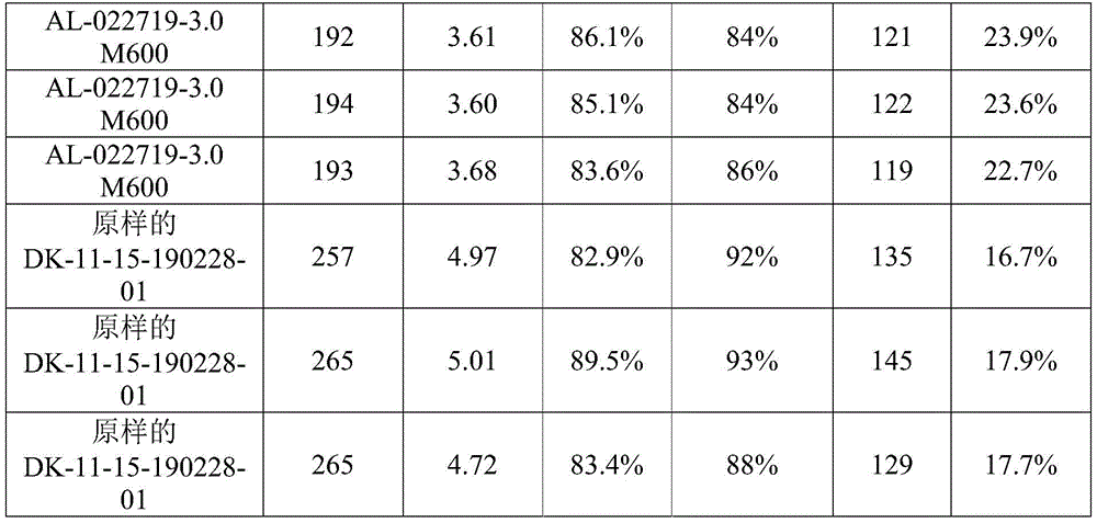
For all conditions, the final smoke FE target is about 85%. It was determined that the loading used to achieve about 85% FE varied during the experiment depending on the slurry composition.
Figure 52 is a graph of smoke FE versus pressure drop illustrating pressure drop loss as a function of slurry composition.
FIG. 53 is a graph of load (g/L) versus pressure drop, which also illustrates the change in pressure drop loss as a function of slurry composition.
FIG. 54 is a graph of efficiency versus settling time (in seconds), again illustrating the change in pressure drop loss as a function of slurry composition.
Table 17 shows the water soak test results.


In Table 17, "FE loss at 0g/L [% ]" shows the change in FE before and after the water test.
The addition of organic dispersants affects the texture and morphology of the agglomerates and the assembly of the agglomerates because they deposit in bulk, which in turn affects FE and dP.
Figures 55A-55C and 56A-56C provide SEM images of spray dried siloxane-alumina agglomerates with PEG-PPG-PEG dispersant, where PEG is polyethylene glycol and PPG is polypropylene glycol. FIGS. 55A and 56A are at 1K magnification; the magnification of fig. 55B and 56B is 10K; and the magnification of fig. 55C and 56C is 25K. Agglomerates made with 3 wt% copolymer in the slurry appeared finer than agglomerates made with 1 wt% copolymer in the slurry. Thus, 4400g/mol (g/mol) of the polyethylene-polypropylene glycol triblock copolymer can increase the fineness and uniformity of the siloxane-alumina agglomerates. Filters having agglomerates and the agglomerates made from such copolymers have been shown to lose < 5% of baseline FE after various durability tests.
Fig. 57-60 provide SEM images of cross-sectional views of unmilled a1000SGD agglomerates using different dispersants. Altering the organic dispersant alters the texture of the resulting agglomerate. Figure 57 shows the case of 1 wt% PEG-PPG-PEG triblock copolymer (4400) dispersant in the slurry. Figure 58 shows the case of 3 wt% PEG-PPG-PEG triblock copolymer (4400) dispersant in the slurry. Fig. 59 shows the case of 3 wt% polypropylene ether diamine (D230) dispersant in the slurry. Fig. 60 shows the case of 3 wt% polyethylene glycol (PEG-400) dispersant in the slurry. The dispersant appears to affect the morphology of the agglomerates.
FIGS. 61A-61B, 62A-62B, and 63A-63B provide SEM images of spray dried siloxane-alumina agglomerates with different dispersants. Figures 61A-61B show spray dried siloxane-alumina agglomerates with a combination of PEG-PPG-PEG dispersant (1.5 wt% in the slurry) and TEA (1.5 wt% in the slurry) at two different magnifications. Fig. 62A-62B show the case of 3 wt% PEG-PPG-PEG triblock copolymer (4400) dispersant in the slurry at two different magnifications. FIGS. 63A-63B show the case of 1 wt% PEG-PPG-PEG triblock copolymer (4400) dispersant in the slurry at two different magnifications. FIGS. 61A-61B, 62A-62B, and 63A-63B illustrate the effect of a dispersant on clusters of agglomerates. When Triethanolamine (TEA) was added to 4400 grams/mole of triblock copolymer, clusters of small agglomerates formed, as opposed to fine and uniform, more discrete agglomerates with only 3% triblock copolymer and less fine, less uniform agglomerates with 1% triblock copolymer. Without intending to be bound by theory, it is believed that both adherent and non-adherent dispersants promote uniformity in agglomerate composition and affect agglomerate structure and allow for desired FE/dP durability.
It will be apparent to those skilled in the art that various modifications and variations can be made to the embodiments described herein without departing from the spirit and scope of the claimed subject matter. Thus, it is intended that the present specification cover the modifications and variations of the various embodiments described herein provided they come within the scope of the appended claims and their equivalents.
Claims (133)
1. A filtration article, comprising:
a honeycomb filter body;
inorganic deposits disposed within the honeycomb filter at a loading of less than or equal to 20 grams of inorganic deposits per liter of honeycomb filter; and
a clean filtration efficiency, prior to exposure to a water durability test, of greater than or equal to 70%, as measured by the clean filtration efficiency test,
wherein, after exposure to the water durability test, the clean filtration efficiency of the filtration article is greater than or equal to 80% of the clean filtration efficiency of the filtration article prior to the water durability test; and is
Wherein the water durability test is selected from the group consisting of: water immersion test, or water spray test.
2. The filtration article of any preceding claim, wherein the filtration article prior to exposure to a water soak test, or a water submergence test, or a water spray test has a clean filtration efficiency of greater than or equal to 85%, or greater than or equal to 90%, or greater than or equal to 95%.
3. The filtration article of any of the preceding claims, wherein the filtration article after exposure to a water durability test has a clean filtration efficiency of greater than or equal to 50%, or greater than or equal to 60%, or greater than or equal to 70%, or greater than or equal to 80%, or greater than or equal to 90%, or greater than or equal to 95%.
4. The filtration article of any of the preceding claims, wherein the inorganic deposits disposed within the honeycomb filter are at a loading of less than or equal to 15 grams of inorganic deposits per liter of honeycomb filter, or less than or equal to 10 grams of inorganic deposits per liter of honeycomb filter, less than or equal to 7 grams of inorganic deposits per liter of honeycomb filter, or less than or equal to 5 grams of inorganic deposits per liter of honeycomb filter.
5. The filtration article of the preceding claim, wherein the inorganic deposits disposed within the honeycomb filter are at a loading of greater than or equal to 1 gram of inorganic deposits per liter of honeycomb filter.
6. The filtration article of any of the preceding claims, wherein the inorganic deposits are free of precious metals.
7. The filtration article of any of the preceding claims, wherein the inorganic deposits are bonded to the honeycomb filter body.
8. The filtration article of any of the preceding claims, wherein at least some of the inorganic deposits are bonded to one another.
9. The filtration article of any of the preceding claims, wherein at least some of the inorganic deposits are disposed in islands.
10. The filtration article of any of the preceding claims, wherein the honeycomb filter body comprises a plurality of porous ceramic walls.
11. The filtration article recited in the preceding claim, wherein at least some of the inorganic deposits are bonded to the porous ceramic walls.
12. The filtration article recited in any one of claims 10 to preceding claim, wherein a portion of a surface of the porous ceramic wall of the inlet channel of the article is free of inorganic deposits.
13. The filtration article of any preceding claim, wherein greater than or equal to 5% of the surface area of the surface of the porous ceramic wall of the inlet channel of the article is free of inorganic deposits.
14. The filtration article of any of claims 10 to any of the preceding claims, wherein the porous ceramic walls comprise a porosity of greater than or equal to 40% to less than or equal to 70%, or the porosity of the porous ceramic walls is greater than or equal to 45% to less than or equal to 65%, or the porosity of the porous ceramic walls is greater than or equal to 50% to less than or equal to 60%, or the porosity of the porous ceramic walls is greater than or equal to 45% to less than or equal to 50%.
15. A filtration article, comprising:
a honeycomb filter comprising a plurality of porous walls comprising a first ceramic composition, wherein the honeycomb filter exhibits a honeycomb filter filtration efficiency as measured by a clean filtration efficiency test;
an inorganic deposit comprising a second ceramic composition at a loading of less than or equal to 20 grams of inorganic deposit per liter of honeycomb filter body; and
a clean filtration efficiency, as measured by a clean filtration efficiency test;
wherein, the clean filtration efficiency is more than or equal to 110% of the filtration efficiency of the honeycomb filter body;
wherein, after exposure to the water durability test, the clean filtration efficiency of the filtration article is greater than or equal to 90% of the clean filtration efficiency of the filtration article prior to the water durability test; and is
Wherein the water durability test is selected from the group consisting of: water immersion test, or water spray test.
16. The filtration article of any preceding claim, wherein the filtration article after exposure to a water soak test, or a water submergence test, or a water spray test has a clean filtration efficiency of greater than or equal to 50%, or greater than or equal to 60%, or greater than or equal to 70%, or greater than or equal to 80%, or greater than or equal to 90%, or greater than or equal to 95%.
17. The filtration article of any of claims 15 to the preceding claims, wherein the clean filtration efficiency of the filtration article prior to exposure to a water soak test, or a water spray test, is greater than or equal to 70%, or greater than or equal to 75%, or greater than or equal to 80%, or greater than or equal to 85%, or greater than or equal to 90%, or greater than or equal to 95%.
18. The filtration article of any of claims 15 to the preceding claim, wherein the inorganic deposits disposed within the honeycomb filter are at a loading of less than or equal to 15 grams of inorganic deposits per liter of honeycomb filter, or less than or equal to 10 grams of inorganic deposits per liter of honeycomb filter, less than or equal to 7 grams of inorganic deposits per liter of honeycomb filter, or less than or equal to 5 grams of inorganic deposits per liter of honeycomb filter.
19. The filtration article of the preceding claim, wherein the inorganic deposits disposed within the honeycomb filter are at a loading of greater than or equal to 1 gram of inorganic deposits per liter of honeycomb filter.
20. The filtration article recited in any one of claims 15 to preceding claim, wherein inorganic deposits are disposed on, in, or both on and in at least a portion of the walls.
21. The filtration article recited in any one of claims 15 to preceding claim, wherein at least some inorganic deposits are bonded to other inorganic deposits.
22. The filtration article of any of claims 15 to the preceding claims, wherein the inorganic deposits comprise alumina nanoparticles.
23. The filtration article recited in any one of claims 15 to preceding claim, wherein at least some inorganic deposits are bonded to a wall.
24. The filtration article recited in any one of claims 15 to preceding claim, wherein inorganic deposits comprise agglomerates of alumina nanoparticles.
25. The filtration article recited in any one of claims 15 to preceding claim, wherein inorganic deposits comprise spherical agglomerates of alumina nanoparticles.
26. The filtration article recited in any one of claims 15 to preceding claim, wherein inorganic deposits comprise aggregates of spherical agglomerates of alumina nanoparticles.
27. The filtration article recited in the preceding claim, wherein said aggregates form a porous inorganic network disposed on at least some portion of the walls.
28. The filtration article recited in any one of claims 15 to preceding claim, wherein at least some inorganic deposits are present in discrete regions on, or in, the wall.
29. The filtration article recited in any one of claims 15 to preceding claim, wherein a portion of the walls do not comprise inorganic deposits.
30. The filtration article recited in claim 15, wherein at least a portion of the inorganic deposits form a porous inorganic network over a portion of the walls.
31. The filtration article recited in the preceding claim, wherein the porous inorganic network comprises an aggregate of spherical agglomerates of refractory metal oxide nanoparticles.
32. The filtration article recited in the preceding claim, wherein at least a portion of the refractory metal oxide nanoparticles are bound by silicon or a silicon-containing compound.
33. The filtration article recited in any one of claims 15 to preceding claim, wherein the porous walls of the honeycomb filter body intersect, said walls comprising surfaces defining a plurality of channels extending in the longitudinal direction from the inlet end to the outlet end, wherein said plurality of channels comprises inlet channels that are open at the inlet end and sealed at a location longitudinally spaced from the inlet end and outlet channels that are open at the outlet end and sealed at a location longitudinally spaced from the outlet end.
34. The filtration article of any of claims 15 to the preceding claims, wherein inorganic deposits are non-uniformly distributed in the longitudinal direction.
35. The filtration article recited in any one of claims 15 to preceding claim, wherein the density of inorganic deposits is greater in a region near the outlet end than at a region near the inlet end.
36. The filtration article of any of claims 15 to the preceding claims, wherein the first composition is selected from the group consisting of: ceramic oxides, ceramic carbides, ceramic nitrides, and combinations thereof.
37. The filtration article recited in any one of claims 15 to preceding claim, wherein the second composition is selected from the group of: ceramic oxides, ceramic carbides, ceramic nitrides, and combinations thereof.
38. The filtration article of any of claims 15 to the preceding claims, wherein the first composition is selected from the group consisting of: cordierite, aluminum titanate, silicon carbide, mullite, spinel, silica, zeolite, zirconia, silicon nitride, zirconium phosphate, alumina, and combinations thereof.
39. The filtration article recited in any one of claims 15 to preceding claim, wherein the second composition is selected from the group of: cordierite, aluminum titanate, silicon carbide, mullite, spinel, silica, zeolite, zirconia, silicon nitride, zirconium phosphate, alumina, and combinations thereof.
40. The filtration article of any of claims 15-foregoing claims, wherein the first composition is cordierite.
41. The filtration article recited in any one of claims 15 to preceding claim, wherein the second composition is alumina.
42. The filtration article of any of claims 15-15, wherein the first composition is cordierite and the second composition is alumina.
43. The filtration article of any of claims 15 through any of the preceding claims, wherein the inorganic deposit comprises a silicon-containing compound.
44. The filtration article of any of claims 15 to the preceding claims, wherein the inorganic deposit comprises silica.
45. The filtration article recited in the preceding claim, wherein at least some of the inorganic deposits are bonded to the porous ceramic walls.
46. The filtration article recited in any one of claims 15 to preceding claim, wherein a portion of a surface of the porous walls of the inlet channel of the article is free of inorganic deposits.
47. The filtration article of the preceding claim, wherein greater than or equal to 5% of the surface area of the surface of the porous walls of the inlet channels of the article is free of inorganic deposits.
48. The filtration article of any of claims 15 to any of the preceding claims, wherein the porous walls comprise a porosity of greater than or equal to 40 to less than or equal to 70%, or the porosity of the porous ceramic walls is greater than or equal to 45% to less than or equal to 65%, or the porosity of the porous ceramic walls is greater than or equal to 50% to less than or equal to 60%, or the porosity of the porous ceramic walls is greater than or equal to 45% to less than or equal to 50%.
49. A filtration article, comprising:
a honeycomb filter body, the honeycomb filter body comprising: a plurality of intersecting porous walls, the walls comprising a surface defining a plurality of channels extending in a longitudinal direction from an inlet end to an outlet end, wherein the plurality of channels comprises an inlet channel open at the inlet end and sealed at a location longitudinally spaced from the inlet end and an outlet channel open at the outlet end and sealed at a location longitudinally spaced from the outlet end, and
inorganic deposits disposed on, or in, or on and in at least some of the walls, and
a silicon-containing precursor binder, a binder,
wherein the inorganic deposits are bonded to each other, to the walls, or to each other and to the walls by a silicon-containing precursor binder.
50. The filtration article recited in claim 49, wherein the silicon-containing precursor binder is a viscoelastic solid.
51. The filtration article recited in claim 49, wherein the silicon-containing precursor binder is a silicone resin.
52. The filtration article recited in claim 49, wherein the silicon-containing precursor binder is a siloxane.
53. The filtration article recited in claim 49, wherein the silicon-containing precursor binder is an alkaline siloxane.
54. The filtration article recited in claim 49, wherein the silicon-containing precursor binder is an alkoxy siloxane.
55. The filtration article recited in claim 49, wherein the silicon-containing precursor binder is a silicate.
56. The filtration article recited in claim 49, wherein the silicon-containing precursor binder is an alkali silicate.
57. The filtration article recited in claim 49, wherein the silicon-containing precursor binder is sodium silicate.
58. The filtration article of claim 49, wherein the silicon-containing precursor binder comprises an inorganic component and an organic component.
59. The filtration article of claim 49, wherein the silicon-containing precursor binder is converted to silica upon application of heat.
60. The filtration article of claim 49, wherein the silicon-containing precursor binder comprises an inorganic component and an organic component, and wherein upon application of heat, the organic component is driven off and the inorganic component is converted to silica.
61. A filtration article, comprising:
a honeycomb filter body comprising a plurality of intersecting porous walls, the walls comprising a surface defining a plurality of channels extending in a longitudinal direction from an inlet end to an outlet end, wherein the plurality of channels comprises inlet channels that are open at the inlet end and sealed at a location longitudinally spaced from the inlet end and outlet channels that are open at the outlet end and sealed at a location longitudinally spaced from the outlet end; and
an inorganic deposit disposed on, or in, or both, at least some of the walls;
wherein the inorganic deposits are bonded to each other, to the wall, or to each other and to the wall;
wherein at least a portion of the inorganic deposits form a porous inorganic network over a portion of the walls; and is
Wherein the clean filtration efficiency of the filtration article is greater than or equal to 70%, as measured by the clean filtration efficiency test.
62. The filtration article recited in claim 61, wherein the filtration article is resistant to moisture such that the article is exposed to a water soak test; water immersion test; the clean filtration efficiency of the article does not vary by more than 5% after water spray testing or combinations thereof.
63. The filtration article recited in claim 61, wherein the clean filtration efficiency of the article does not change by more than 5% after exposure to a high airflow test, a reverse airflow test, a vibration test, a high temperature test, or a combination thereof.
64. The filtration article of any of claims 61 to the preceding claim, wherein the inorganic deposits disposed within the honeycomb filter are at a loading of less than or equal to 15 grams of inorganic deposits per liter of honeycomb filter, or less than or equal to 10 grams of inorganic deposits per liter of honeycomb filter, less than or equal to 7 grams of inorganic deposits per liter of honeycomb filter, or less than or equal to 5 grams of inorganic deposits per liter of honeycomb filter.
65. The filtration article of the preceding claim, wherein the inorganic deposits disposed within the honeycomb filter are at a loading of greater than or equal to 1 gram of inorganic deposits per liter of honeycomb filter.
66. The filtration article of any of claims 61 to the preceding claim, wherein the inorganic deposit has a porosity of greater than or equal to 70%, or greater than or equal to 80%, or greater than or equal to 90%, or greater than or equal to 95%.
67. The filtration article recited in claim 61, wherein the inorganic material comprises refractory nanoparticles.
68. The filtration article recited in claim 61, wherein at least some inorganic deposits are present in discrete regions on, or in, the wall.
69. The filtration article of claim 61, wherein at least some of the inorganic deposits form a porous inorganic interlaced microstructure over a portion of a surface of some of the walls.
70. The filtration article recited in claim 61, wherein at least some surfaces of some of the walls do not comprise inorganic deposits.
71. The filtration article recited in claim 61, wherein the inorganic deposits comprise agglomerates of refractory nanoparticles.
72. The filtration article recited in the preceding claim, wherein the agglomerates are spherical in shape.
73. The filtration article recited in claim 61, wherein the inorganic deposits comprise individual agglomerates, clusters of agglomerates, or both individual agglomerates and clusters of agglomerates.
74. The filtration article recited in the preceding claim, wherein said tufts are long or tufted in shape.
75. The filtration article recited in claim 61, wherein the inorganic deposits are non-uniformly distributed in the longitudinal direction.
76. The filtration article recited in claim 61, wherein the accumulation of inorganic deposits is higher at open portions distal from the channels.
77. The filtration article recited in claim 61, wherein the inorganic deposit further comprises an inorganic binder that binds the refractory nanoparticles to each other, or to the wall, or both.
78. The filtration article of claim 77, wherein the inorganic binder comprises one or more components having a melting point greater than 1000 ℃.
79. The filtration article of claim 77, wherein the inorganic binder comprises one or more components that are stable at a temperature greater than or equal to 400 ℃, 500 ℃, 600 ℃, 700 ℃, 800 ℃, 900 ℃, 1000 ℃, 1100 ℃, 1200 ℃, or 1300 ℃.
80. The filtration article of claim 77, wherein the inorganic binder comprises a silicon-containing compound.
81. The filtration article of claim 77, wherein the inorganic binder comprises silica.
82. A filtration article, comprising:
a honeycomb body comprising a plurality of intersecting porous walls, the walls comprising a surface defining a plurality of channels extending from an inlet end to an outlet end, wherein the plurality of channels comprises inlet channels sealed at a location spaced from the inlet end and outlet channels sealed at a location spaced from the outlet end; and
An inorganic deposit disposed on, in, or both on and in at least some of the walls defining the inlet passage;
wherein the clean filtration efficiency of the filtration article is greater than or equal to 70%, as measured by the clean filtration efficiency test; and is
Wherein the filtration article is resistant to moisture, such that it is tested by exposure to water immersion; water immersion test; the clean filtration efficiency of the article does not vary by more than 5% after water spray testing or combinations thereof.
83. A filtration article, comprising:
a honeycomb body comprising a plurality of intersecting porous walls, the walls comprising a surface defining a plurality of channels extending from an inlet end to an outlet end, wherein the plurality of channels comprises inlet channels sealed at a location spaced from the inlet end and outlet channels sealed at a location spaced from the outlet end; and
an inorganic deposit disposed on, in, or both on and in at least some of the walls defining the inlet passage;
wherein the inorganic deposit comprises refractory inorganic nanoparticles bound by a high temperature binder comprising one or more inorganic components;
Wherein the clean filtration efficiency of the filtration article is greater than or equal to 70%, as measured by the clean filtration efficiency test; and is
Wherein the filtration article is resistant to moisture, such that it is tested by exposure to water immersion; water immersion test; the clean filtration efficiency of the article does not vary by more than 5% after water spray testing or combinations thereof.
84. The filtration article of claim 83, wherein at least a portion of the inorganic deposits form a porous inorganic network over a portion of the walls.
85. The filtration article recited in claim 83 or 84, wherein the inorganic deposits comprise refractory metal oxide nanoparticles.
86. The filtration article recited in claim 83, wherein inorganic deposits comprise nanoparticles in the form of agglomerates.
87. The filtration article recited in claim 83, wherein the inorganic deposits comprise aggregates of spherical agglomerates of nanoparticles.
88. The filtration article recited in the preceding claim, wherein the nanoparticles comprise alumina.
89. The filtration article of claim 83, wherein the high temperature binder comprises at least one component that is stable at a temperature greater than or equal to 400 ℃, 500 ℃, 600 ℃, 700 ℃, 800 ℃, 900 ℃, 1000 ℃, 1100 ℃, 1200 ℃, or 1300 ℃.
90. The filtration article recited in claim 83, wherein the high temperature binder comprises silicon.
91. The filtration article recited in claim 83, wherein the high temperature binder is a silicone resin.
92. The filtration article recited in claim 83, wherein the high temperature binder is a siloxane.
93. The filtration article recited in claim 83, wherein the high temperature binder is an alkoxy siloxane.
94. The filtration article recited in claim 83, wherein the high temperature binder is a silicate.
95. The filtration article recited in claim 83, wherein the high temperature binder is an alkali silicate.
96. The filtration article recited in claim 83, wherein the high temperature binder is sodium silicate.
97. A filtration article, comprising:
a honeycomb body comprising a plurality of intersecting porous walls, the walls comprising a surface defining a plurality of channels extending from an inlet end to an outlet end, wherein the plurality of channels comprises inlet channels sealed at a location spaced from the inlet end and outlet channels sealed at a location spaced from the outlet end; and
an inorganic material disposed on, in, or both at and in at least some of the walls defining the inlet channel;
Wherein the clean filtration efficiency of the filtration article is greater than or equal to 70%, as measured by the clean filtration efficiency test; and is
Wherein the filtration article is resistant to moisture, such that it is tested by exposure to water immersion; water immersion test; the clean filtration efficiency of the article does not vary by more than 5% after water spray testing or combinations thereof.
98. A filtration article, comprising:
a honeycomb body comprising a plurality of intersecting porous walls, the walls comprising a surface defining a plurality of channels extending from an inlet end to an outlet end, wherein the plurality of channels comprises inlet channels sealed at a location spaced from the inlet end and outlet channels sealed at a location spaced from the outlet end; and
a porous inorganic network of refractory metal oxide nanoparticles disposed on, in, or both on and in at least some of the walls defining the inlet channel,
wherein the refractory metal oxide nanoparticles are bonded by a high temperature binder comprising one or more inorganic components,
wherein the clean filtration efficiency of the filtration article is greater than or equal to 70%, as measured by the clean filtration efficiency test; and is
Wherein the filtration article is resistant to moisture, such that it is tested by exposure to water immersion; water immersion test; the clean filtration efficiency of the article does not vary by more than 5% after water spray testing or combinations thereof.
99. The filtration article of claim 98, wherein the high temperature binder is provided by a silicon-containing binder precursor.
100. The filtration article of any preceding claim, wherein the high temperature binder comprises at least one component that is stable at a temperature greater than or equal to 400 ℃, 500 ℃, 600 ℃, 700 ℃, 800 ℃, 900 ℃, 1000 ℃, 1100 ℃, 1200 ℃, or 1300 ℃.
101. The filtration article recited in claim 98, wherein the high temperature binder comprises silicon.
102. The filtration article of claim 99, wherein the silicon-containing binder binds some of the refractory metal oxide nanoparticles to one another.
103. The filtration article of claim 99, wherein the silicon-containing binder binds some of the refractory metal oxide nanoparticles to porous walls of the honeycomb body.
104. The filtration article of claim 99, wherein the silicon-containing binder bonds the refractory metal oxide nanoparticles to each other and to the porous walls of the honeycomb body.
105. The filtration article of claim 99, wherein the silicon-containing binder is one or more of the group consisting of: silica, silicone resin, sodium silicate, colloidal silica, and combinations thereof.
106. The filtration article of claim 99, wherein the silicon-containing binder precursor is a silicone resin.
107. The filtration article of claim 99, wherein the silicon-containing binder precursor is a siloxane.
108. The filtration article of claim 99, wherein the silicon-containing binder precursor is an alkoxy siloxane.
109. The filtration article recited in claim 99, wherein the silicon-containing binder precursor is a silicate.
110. The filtration article recited in claim 99, wherein the silicon-containing binder precursor is an alkali silicate.
111. The filtration article of claim 99, wherein the silicon-containing binder precursor is sodium silicate.
112. A filtration article, comprising:
a honeycomb filter body comprising a porous wall having pores; and
an inorganic deposit comprising nanoparticles of an inorganic material and a binder disposed within a honeycomb filter body;
wherein the inorganic deposit comprises a network of aggregated agglomerates of inorganic material nanoparticles and a binder comprising an alcohol-soluble binder.
113. The filtration article recited in claim 112, wherein the agglomerates comprise nanoparticles of an inorganic material, and the network of agglomerates comprises aggregates of the agglomerates.
114. The filtration article recited in claim 113, wherein the network of agglomerates comprises clusters or chains of aggregates.
115. The filtration article of claim 114, wherein at least a portion of the clusters or chains are disposed within pores in or below the surface of the porous wall, and at least a portion of the clusters or chains are disposed on the surface of the porous wall.
116. The filtration article of claim 114 or 115, wherein a portion of the clusters are porous clusters comprising exposed agglomerates.
117. The filtration article of claim 116, wherein the porous cluster comprises one or more chains having two or more agglomerates, each chain extending in an outward direction from the porous wall.
118. The filtration article of claim 116, wherein the porous clusters comprise a plurality of outwardly extending chains that together provide a topography similar to a member of the group consisting of fingers, tufts, and sponges.
119. The filtration article as recited in any one of claims 112-118, wherein the inorganic material comprises one or more of ceramic particles, metal oxide particles, and refractory metal oxide particles.
120. The filter article of any of claims 112-119, wherein the inorganic material comprises alumina.
121. The filtration article of any of claims 112-120, wherein the inorganic material is present on the honeycomb filter at a loading of 1-20g/L or 1-10 g/L.
122. The filtration article of any of claims 112-121, wherein the inorganic material has a porosity of greater than 80% and less than 95%.
123. The filtration article of any of claims 112-122, wherein the alcohol-soluble binder comprises a silicon-containing binder.
124. The filtration article as recited in any one of claims 112-123, wherein the binder comprises an alkoxy siloxane.
125. The filter article of any of claims 112-124, wherein the binder is present on the honeycomb filter body in an amount of 5% to about 30% by weight of the inorganic material.
126. A filtration article, comprising:
a honeycomb filter body comprising a porous wall having pores; and
an aggregate of agglomerates comprising inorganic material nanoparticles and a silicon-containing binder disposed within a honeycomb filter;
wherein the aggregate is present at a loading (g/L) of 0.1 to 20 grams per volume of honeycomb filter in liters.
127. The filtration article of claim 126, wherein at least a portion of the aggregates are disposed within pores on the outer surface or within pores below the surface of the porous wall.
128. The filtration article of any of claims 126-127, wherein the inorganic material comprises alumina.
129. The filtration article of any of claims 126-128, wherein the binder is alcohol-soluble or water-soluble.
130. The filtration article as recited in any one of claims 126-129, wherein the binder comprises an alkoxy siloxane.
131. The filtration article as recited in any one of claims 126-129, wherein the binder comprises sodium silicate.
132. The filtration article of any of claims 126-131, wherein the binder is present on the honeycomb filter body in an amount of from 5% to about 30% by weight of the inorganic material.
133. The filtration article as recited in any one of claims 126-132, wherein the inorganic deposit is free of rare earth oxides, platinum group metals, and molecular sieves.
Applications Claiming Priority (5)
| Application Number | Priority Date | Filing Date | Title |
|---|---|---|---|
| US201862726192P | 2018-08-31 | 2018-08-31 | |
| US62/726,192 | 2018-08-31 | ||
| PCT/CN2018/103807 WO2020047708A1 (en) | 2018-09-03 | 2018-09-03 | Honeycomb body with porous material |
| CNPCT/CN2018/103807 | 2018-09-03 | ||
| PCT/US2019/049209 WO2020047503A2 (en) | 2018-08-31 | 2019-08-30 | Methods of making honeycomb bodies having inorganic filtration deposits |
Publications (1)
| Publication Number | Publication Date |
|---|---|
| CN113286772A true CN113286772A (en) | 2021-08-20 |
Family
ID=67957433
Family Applications (3)
| Application Number | Title | Priority Date | Filing Date |
|---|---|---|---|
| CN201980072251.1A Pending CN113286772A (en) | 2018-08-31 | 2019-08-30 | Method for producing honeycombed body with inorganic filter deposit |
| CN201980072129.4A Pending CN113286771A (en) | 2018-08-31 | 2019-08-30 | Method for producing honeycombed body with inorganic filter deposit |
| CN201980072228.2A Pending CN113302170A (en) | 2018-08-31 | 2019-08-30 | Method for producing honeycombed body with inorganic filter deposit |
Family Applications After (2)
| Application Number | Title | Priority Date | Filing Date |
|---|---|---|---|
| CN201980072129.4A Pending CN113286771A (en) | 2018-08-31 | 2019-08-30 | Method for producing honeycombed body with inorganic filter deposit |
| CN201980072228.2A Pending CN113302170A (en) | 2018-08-31 | 2019-08-30 | Method for producing honeycombed body with inorganic filter deposit |
Country Status (6)
| Country | Link |
|---|---|
| US (4) | US12091366B2 (en) |
| EP (4) | EP3844127B1 (en) |
| JP (4) | JP7608327B2 (en) |
| CN (3) | CN113286772A (en) |
| MX (1) | MX2021002442A (en) |
| WO (3) | WO2020047479A1 (en) |
Families Citing this family (26)
| Publication number | Priority date | Publication date | Assignee | Title |
|---|---|---|---|---|
| CN112996763A (en) | 2018-08-31 | 2021-06-18 | 康宁股份有限公司 | Method for producing honeycombed body with inorganic filter deposit |
| CN113286772A (en) | 2018-08-31 | 2021-08-20 | 康宁股份有限公司 | Method for producing honeycombed body with inorganic filter deposit |
| CN113348156B (en) | 2018-09-03 | 2023-10-27 | 康宁股份有限公司 | Honeycomb body with porous material |
| JP7118919B2 (en) * | 2019-03-29 | 2022-08-16 | 株式会社Soken | Exhaust gas purification filter |
| US20230173535A1 (en) * | 2020-04-28 | 2023-06-08 | Corning Incorporated | Aerosol deposition apparatus, method, and filter body with deposits |
| WO2022006768A1 (en) * | 2020-07-08 | 2022-01-13 | Corning Incorporated | Increasing and measuring filtration efficiency of a honeycomb body |
| WO2022006767A1 (en) | 2020-07-08 | 2022-01-13 | Corning Incorporated | Offline measurement of honeycomb body filtration efficiency |
| JP7798799B2 (en) * | 2020-12-16 | 2026-01-14 | ユミコア日本触媒株式会社 | Particulate filter, method for removing particulate matter from the exhaust gas of an internal combustion engine, and method for manufacturing a particulate filter |
| JP7690073B2 (en) * | 2021-08-20 | 2025-06-09 | ジョンソン、マッセイ、パブリック、リミテッド、カンパニー | Particulate filter improvements or improvements relating thereto |
| EP4140581A1 (en) * | 2021-08-27 | 2023-03-01 | Johnson Matthey Public Limited Company | Method of forming an inorganic oxide coating on a monolith article |
| US12257539B2 (en) * | 2021-08-31 | 2025-03-25 | Corning Incorporated | Reinforced exhaust treatment article, exhaust line, and methods |
| CN113713605A (en) * | 2021-09-03 | 2021-11-30 | 常州翡尔达环保科技有限公司 | Air purification biological filtration material particle and preparation method and application thereof |
| WO2023108589A1 (en) * | 2021-12-17 | 2023-06-22 | Corning Incorporated | Methods of making honeycomb bodies having inorganic filtration deposits |
| US20250269390A1 (en) * | 2022-04-28 | 2025-08-28 | Corning Incorporated | Apparatus and methods for making honeycomb bodies having deposits of inorganic particles |
| US20250381523A1 (en) | 2022-07-21 | 2025-12-18 | Corning Incorporated | Wall-flow filter and methods for inhibiting release of very fine nano-particles in exhaust emissions |
| DE102022002854A1 (en) | 2022-08-05 | 2024-02-08 | Umicore Ag & Co. Kg | Catalytically active particle filter with high filtration efficiency and oxidation function |
| GB2621175B (en) * | 2022-08-05 | 2024-12-25 | Johnson Matthey Plc | Coated filters |
| EP4619131A1 (en) * | 2022-11-18 | 2025-09-24 | Corning Incorporated | Methods of making filtration articles having filtration material deposits |
| EP4374952A1 (en) * | 2022-11-28 | 2024-05-29 | Johnson Matthey Public Limited Company | Coatings on a monolith article |
| WO2024118491A1 (en) * | 2022-11-29 | 2024-06-06 | Corning Incorporated | Methods of depositing inorganic particles |
| CN120476012A (en) * | 2022-11-30 | 2025-08-12 | 康宁股份有限公司 | Method for producing a filter article having a filter material deposit |
| EP4626579A1 (en) * | 2022-11-30 | 2025-10-08 | Corning Incorporated | Filtration articles having filtration material deposits with multimodal size distribution |
| JP7792924B2 (en) * | 2023-03-30 | 2025-12-26 | 日本碍子株式会社 | Pillar honeycomb structure filter and manufacturing method thereof |
| CN121419952A (en) | 2023-06-30 | 2026-01-27 | 康宁股份有限公司 | Methods for surface treatment of honeycomb structures with inorganic deposits |
| WO2025111155A1 (en) * | 2023-11-22 | 2025-05-30 | Corning Incorporated | Filtration articles having nanoparticle based filtration material |
| WO2025117174A1 (en) * | 2023-11-27 | 2025-06-05 | Corning Incorporated | Methods of treating a porous ceramic body with inorganic particles |
Citations (8)
| Publication number | Priority date | Publication date | Assignee | Title |
|---|---|---|---|---|
| CN1512972A (en) * | 2001-04-23 | 2004-07-14 | Method for manufacturing wall-flow monolithic filter | |
| EP1775021A1 (en) * | 2005-10-12 | 2007-04-18 | Honda Motor Company Ltd. | Process of producing a catalytic coating and catalyst filters |
| EP1775022A1 (en) * | 2005-10-12 | 2007-04-18 | HONDA MOTOR CO., Ltd. | Process of producing a catalytic coating and catalyst filters |
| US20100126133A1 (en) * | 2008-11-26 | 2010-05-27 | Curtis Robert Fekety | Coated Particulate Filter And Method |
| US20140272276A1 (en) * | 2013-03-15 | 2014-09-18 | Corning Incorporated | Cellular Ceramic Article and Method For Manufacturing The Same |
| US9040003B2 (en) * | 2010-02-01 | 2015-05-26 | Johnson Matthey Public Limited Company | Three way catalyst comprising extruded solid body |
| CN105503232A (en) * | 2015-12-01 | 2016-04-20 | 南京柯瑞特种陶瓷股份有限公司 | Preparation of wall-flow SiC honeycomb ceramic filter |
| WO2017075328A1 (en) * | 2015-10-30 | 2017-05-04 | Corning Incorporated | Porous ceramic filters and methods for making the same |
Family Cites Families (68)
| Publication number | Priority date | Publication date | Assignee | Title |
|---|---|---|---|---|
| US4676740A (en) * | 1986-03-24 | 1987-06-30 | Debeus Anthony J | Heat exchange apparatus and process for rotary kilns |
| US4932591A (en) * | 1988-03-21 | 1990-06-12 | Cruz Luis R | Pulverizer, fluid |
| US5194078A (en) * | 1990-02-23 | 1993-03-16 | Matsushita Electric Industrial Co., Ltd. | Exhaust filter element and exhaust gas-treating apparatus |
| JP3057312B2 (en) | 1994-06-09 | 2000-06-26 | 株式会社クボタ | Ceramic porous body for filtration and separation |
| US6207101B1 (en) * | 1999-09-30 | 2001-03-27 | Corning Incorporated | Method of making fired bodies |
| JP3756721B2 (en) | 2000-03-24 | 2006-03-15 | 日本碍子株式会社 | Exhaust gas purification filter |
| EP1415072B1 (en) | 2001-08-08 | 2006-12-13 | Toyota Jidosha Kabushiki Kaisha | An exhaust gas purification device |
| DE60222225T2 (en) | 2001-12-03 | 2008-06-12 | Hitachi Metals, Ltd. | Ceramic honeycomb filter |
| EP1495790A4 (en) | 2002-04-09 | 2005-01-26 | Ibiden Co Ltd | Honeycomb filter for clarification of exhaust gas |
| US7241763B2 (en) | 2002-07-15 | 2007-07-10 | Janssen Pharmaceutica N.V. | 3-furanyl analogs of toxoflavine as kinase inhibitors |
| US20040176246A1 (en) * | 2003-03-05 | 2004-09-09 | 3M Innovative Properties Company | Catalyzing filters and methods of making |
| JPWO2006006667A1 (en) | 2004-07-14 | 2008-05-01 | 日本碍子株式会社 | Method for manufacturing porous honeycomb structure |
| US7520918B2 (en) | 2004-12-21 | 2009-04-21 | Corning Incorporated | Method and system for identifying and repairing defective cells in a plugged honeycomb structure |
| WO2007097056A1 (en) | 2006-02-23 | 2007-08-30 | Ibiden Co., Ltd. | Honeycomb structure and exhaust gas purifier |
| MX349614B (en) | 2006-10-19 | 2017-07-26 | Nanomech Inc | Methods and apparatus for making coatings using ultrasonic spray deposition. |
| US8298311B2 (en) | 2006-11-15 | 2012-10-30 | Corning Incorporated | Filters with controlled submicron porosity |
| EP2158956B1 (en) * | 2007-04-27 | 2014-10-08 | NGK Insulators, Ltd. | Honeycomb filter |
| FR2916366B1 (en) | 2007-05-23 | 2009-11-27 | Saint Gobain Ct Recherches | TEXTURE PARTICLE FILTER FOR CATALYTIC APPLICATIONS |
| US7767256B2 (en) | 2007-05-31 | 2010-08-03 | Corning Incorporated | Method for preparing a porous inorganic coating on a porous support using certain pore fillers |
| US7704296B2 (en) * | 2007-11-27 | 2010-04-27 | Corning Incorporated | Fine porosity low-microcracked ceramic honeycombs and methods thereof |
| US8258137B2 (en) * | 2008-01-29 | 2012-09-04 | Katholieke Universiteit Leuven | Process for release of biologically active species from mesoporous oxide systems |
| WO2009101683A1 (en) | 2008-02-13 | 2009-08-20 | Ibiden Co., Ltd. | Process for producing honeycomb structure |
| DE102008000287A1 (en) * | 2008-02-13 | 2009-08-20 | Evonik Goldschmidt Gmbh | Reactive, liquid ceramic binder |
| GB0903262D0 (en) | 2009-02-26 | 2009-04-08 | Johnson Matthey Plc | Filter |
| US8435595B2 (en) * | 2009-07-15 | 2013-05-07 | Empire Technology Development, Llc | Carbon nanotube transparent films |
| EP2483218B1 (en) | 2009-09-28 | 2016-03-16 | Corning Inc. | Method of making membrane filter |
| KR101232921B1 (en) * | 2009-11-18 | 2013-02-13 | 토쿄 요교 가부시키가이샤 | Heat resistant sealing agent |
| JP5597146B2 (en) | 2010-03-18 | 2014-10-01 | 日本碍子株式会社 | Honeycomb filter manufacturing equipment |
| JP5597148B2 (en) * | 2010-03-18 | 2014-10-01 | 日本碍子株式会社 | Honeycomb filter manufacturing equipment |
| EP2556871B1 (en) | 2010-03-31 | 2016-09-07 | NGK Insulators, Ltd. | Honeycomb filter |
| EP2390307A1 (en) | 2010-05-27 | 2011-11-30 | Corning Incorporated | Porous ceramic processing using prilled wax and non-ionic surfactant |
| GB201100595D0 (en) | 2010-06-02 | 2011-03-02 | Johnson Matthey Plc | Filtration improvements |
| CN103080047A (en) | 2010-08-31 | 2013-05-01 | 康宁股份有限公司 | Cellular ceramic articles with coated channels and methods for making the same |
| EP2611756B1 (en) | 2010-09-01 | 2017-10-25 | Dow Global Technologies LLC | Method for applying discriminating layer onto porous ceramic filters via gas-borne prefabricated porous assemblies |
| KR101856799B1 (en) | 2010-09-01 | 2018-05-10 | 다우 글로벌 테크놀로지스 엘엘씨 | Method for applying discriminating layer onto porous ceramic filters |
| JP5597084B2 (en) | 2010-09-30 | 2014-10-01 | 日本碍子株式会社 | Manufacturing method of honeycomb structure |
| EP2625314A1 (en) * | 2010-10-06 | 2013-08-14 | 3M Innovative Properties Company | Anti-reflective articles with nanosilica-based coatings and barrier layer |
| EP2625313B1 (en) * | 2010-10-06 | 2020-12-09 | 3M Innovative Properties Company | Anti-reflective articles with nanosilica-based coatings |
| FR2969513B1 (en) * | 2010-12-22 | 2013-04-12 | IFP Energies Nouvelles | PROCESS FOR THE PREPARATION OF A SPHERICAL MATERIAL HIERARCHISED POROSITY COMPRISING METALLIC PARTICLES PIEGEES IN A MESOSTRUCTURED MATRIX |
| US10155361B2 (en) * | 2011-11-09 | 2018-12-18 | Corning Incorporated | Method of binding nanoparticles to glass |
| JP2013043138A (en) | 2011-08-25 | 2013-03-04 | Denso Corp | Catalyst carrier and method for producing the same |
| JP6075291B2 (en) | 2011-10-11 | 2017-02-08 | 日立金属株式会社 | Method for manufacturing ceramic honeycomb structure and ceramic honeycomb structure |
| WO2013145323A1 (en) * | 2012-03-30 | 2013-10-03 | イビデン株式会社 | Honeycomb filter |
| WO2013145316A1 (en) | 2012-03-30 | 2013-10-03 | イビデン株式会社 | Honeycomb filter and production method for honeycomb filter |
| EP2832414B1 (en) * | 2012-03-30 | 2019-06-26 | Ibiden Co., Ltd. | Production method for honeycomb filter |
| US8960571B2 (en) * | 2012-08-17 | 2015-02-24 | Spraying Systems Co. | Full cone air-assisted spray nozzle assembly |
| WO2014073066A1 (en) | 2012-11-08 | 2014-05-15 | イビデン株式会社 | Honeycomb structure and manufacturing method thereof |
| US9523623B2 (en) * | 2012-11-28 | 2016-12-20 | Corning Incorporated | Methods for testing a honeycomb filter |
| JP6114023B2 (en) | 2012-12-18 | 2017-04-12 | 日本碍子株式会社 | Particulate filter |
| BR112015029292B1 (en) * | 2013-05-21 | 2022-06-14 | 3M Innovative Properties Company | NANOSTRUCTURED SPORE CARRIER |
| JP6122730B2 (en) | 2013-08-08 | 2017-04-26 | 積水化学工業株式会社 | Film forming method, film forming apparatus, photoelectrode manufacturing method, and dye-sensitized solar cell manufacturing method |
| CN104801114B (en) | 2014-01-24 | 2017-05-03 | 宜兴市科创环保有限公司 | Ceramic filtering element |
| EP3137432B1 (en) * | 2014-05-01 | 2018-06-13 | Corning Incorporated | Honeycomb structure comprising a cement skin composition with crystalline inorganic fibrous material and method of manufacturing it |
| US9764313B2 (en) * | 2014-06-18 | 2017-09-19 | Basf Corporation | Molecular sieve catalyst compositions, catalyst composites, systems, and methods |
| WO2016140316A1 (en) * | 2015-03-04 | 2016-09-09 | 国立大学法人九州大学 | Silica glass precursor production method, silica glass precursor, silica glass production method and silica glass precursor |
| JP6389134B2 (en) | 2015-03-20 | 2018-09-12 | 日本碍子株式会社 | Method for manufacturing plugged honeycomb structure, and plugged honeycomb structure |
| CN108367224B (en) | 2015-12-09 | 2022-04-29 | 康宁股份有限公司 | Porous ceramic materials, filters and articles |
| WO2018019957A1 (en) * | 2016-07-28 | 2018-02-01 | Imerys | Ceramics processing |
| US11248129B2 (en) * | 2016-10-28 | 2022-02-15 | Ohio State Innovation Foundation | Liquid impregnated surfaces for liquid repellancy |
| FR3061708B1 (en) * | 2017-01-06 | 2021-10-22 | Commissariat Energie Atomique | PROCESS FOR PREPARING HEART-SHELL HYBRID MATERIALS |
| WO2018191316A1 (en) * | 2017-04-10 | 2018-10-18 | Cornell University | Sulfur- or heavy atom-containing nanoparticles, methods of making same, and uses thereof |
| US11105234B2 (en) * | 2017-08-11 | 2021-08-31 | Ford Global Technologies, Llc | Particulate filters |
| CN111511455B (en) | 2017-10-31 | 2023-03-31 | 康宁股份有限公司 | Honeycomb body and particle filter comprising a honeycomb body |
| JP2019155276A (en) * | 2018-03-13 | 2019-09-19 | イビデン株式会社 | Honeycomb filter and method for production thereof |
| FR3083682B1 (en) * | 2018-07-12 | 2020-12-11 | Ethera | ANTI-ODOR COVER |
| CN113286772A (en) | 2018-08-31 | 2021-08-20 | 康宁股份有限公司 | Method for producing honeycombed body with inorganic filter deposit |
| CN112996763A (en) * | 2018-08-31 | 2021-06-18 | 康宁股份有限公司 | Method for producing honeycombed body with inorganic filter deposit |
| US12345677B2 (en) * | 2020-06-09 | 2025-07-01 | Cardea Bio, Inc. | Integrated circuit with 2D FETs for direct and indirect target signal measurement |
-
2019
- 2019-08-30 CN CN201980072251.1A patent/CN113286772A/en active Pending
- 2019-08-30 EP EP19769656.0A patent/EP3844127B1/en active Active
- 2019-08-30 US US17/272,175 patent/US12091366B2/en active Active
- 2019-08-30 WO PCT/US2019/049167 patent/WO2020047479A1/en not_active Ceased
- 2019-08-30 EP EP19769330.2A patent/EP3844126A1/en active Pending
- 2019-08-30 JP JP2021511533A patent/JP7608327B2/en active Active
- 2019-08-30 CN CN201980072129.4A patent/CN113286771A/en active Pending
- 2019-08-30 JP JP2021511649A patent/JP7466526B2/en active Active
- 2019-08-30 CN CN201980072228.2A patent/CN113302170A/en active Pending
- 2019-08-30 EP EP19769665.1A patent/EP3844128A2/en active Pending
- 2019-08-30 EP EP25173574.2A patent/EP4570778A1/en active Pending
- 2019-08-30 WO PCT/US2019/049209 patent/WO2020047503A2/en not_active Ceased
- 2019-08-30 JP JP2021511638A patent/JP7660500B2/en active Active
- 2019-08-30 US US17/272,085 patent/US20210347702A1/en active Pending
- 2019-08-30 WO PCT/US2019/049213 patent/WO2020047506A1/en not_active Ceased
- 2019-08-30 US US17/271,505 patent/US20210197105A1/en not_active Abandoned
- 2019-08-30 MX MX2021002442A patent/MX2021002442A/en unknown
-
2024
- 2024-08-09 US US18/799,161 patent/US20240400465A1/en active Pending
- 2024-11-18 JP JP2024200755A patent/JP2025026934A/en active Pending
Patent Citations (8)
| Publication number | Priority date | Publication date | Assignee | Title |
|---|---|---|---|---|
| CN1512972A (en) * | 2001-04-23 | 2004-07-14 | Method for manufacturing wall-flow monolithic filter | |
| EP1775021A1 (en) * | 2005-10-12 | 2007-04-18 | Honda Motor Company Ltd. | Process of producing a catalytic coating and catalyst filters |
| EP1775022A1 (en) * | 2005-10-12 | 2007-04-18 | HONDA MOTOR CO., Ltd. | Process of producing a catalytic coating and catalyst filters |
| US20100126133A1 (en) * | 2008-11-26 | 2010-05-27 | Curtis Robert Fekety | Coated Particulate Filter And Method |
| US9040003B2 (en) * | 2010-02-01 | 2015-05-26 | Johnson Matthey Public Limited Company | Three way catalyst comprising extruded solid body |
| US20140272276A1 (en) * | 2013-03-15 | 2014-09-18 | Corning Incorporated | Cellular Ceramic Article and Method For Manufacturing The Same |
| WO2017075328A1 (en) * | 2015-10-30 | 2017-05-04 | Corning Incorporated | Porous ceramic filters and methods for making the same |
| CN105503232A (en) * | 2015-12-01 | 2016-04-20 | 南京柯瑞特种陶瓷股份有限公司 | Preparation of wall-flow SiC honeycomb ceramic filter |
Also Published As
| Publication number | Publication date |
|---|---|
| JP7608327B2 (en) | 2025-01-06 |
| US12091366B2 (en) | 2024-09-17 |
| US20210347702A1 (en) | 2021-11-11 |
| JP2021535069A (en) | 2021-12-16 |
| WO2020047506A1 (en) | 2020-03-05 |
| EP3844127B1 (en) | 2025-06-04 |
| US20210354071A1 (en) | 2021-11-18 |
| JP7660500B2 (en) | 2025-04-11 |
| US20240400465A1 (en) | 2024-12-05 |
| JP2021535067A (en) | 2021-12-16 |
| WO2020047503A3 (en) | 2020-04-02 |
| EP3844126A1 (en) | 2021-07-07 |
| EP4570778A1 (en) | 2025-06-18 |
| JP7466526B2 (en) | 2024-04-12 |
| JP2025026934A (en) | 2025-02-26 |
| US20210197105A1 (en) | 2021-07-01 |
| EP3844128A2 (en) | 2021-07-07 |
| JP2021535066A (en) | 2021-12-16 |
| EP3844127A1 (en) | 2021-07-07 |
| MX2021002442A (en) | 2021-09-21 |
| CN113302170A (en) | 2021-08-24 |
| WO2020047479A1 (en) | 2020-03-05 |
| WO2020047503A2 (en) | 2020-03-05 |
| CN113286771A (en) | 2021-08-20 |
Similar Documents
| Publication | Publication Date | Title |
|---|---|---|
| JP7660500B2 (en) | Method for manufacturing a honeycomb body having an inorganic filtration deposit - Patents.com | |
| JP7825351B2 (en) | Honeycomb body having porous material | |
| US12595215B2 (en) | Methods of making honeycomb bodies having inorganic filtration deposits | |
| CN112996763A (en) | Method for producing honeycombed body with inorganic filter deposit | |
| WO2024113256A1 (en) | Filtration articles having filtration material deposits with multimodal size distribution | |
| US20250002418A1 (en) | Methods of making honeycomb bodies having inorganic filtration deposits | |
| WO2024107349A1 (en) | Methods of making filtration articles having filtration material deposits | |
| US20250001360A1 (en) | Emissions treatment articles with inorganic filtration deposits and catalytic material | |
| WO2024113251A1 (en) | Methods of making filtration articles having filtration material deposits | |
| US20240408544A1 (en) | Emissions treatment articles with inorganic filtration deposits and catalytic material | |
| CN118234558A (en) | Emission treatment article having inorganic filter deposits and catalytic materials | |
| CN118302238A (en) | Wall flow honeycomb filter and manufacturing method |
Legal Events
| Date | Code | Title | Description |
|---|---|---|---|
| PB01 | Publication | ||
| PB01 | Publication | ||
| SE01 | Entry into force of request for substantive examination | ||
| SE01 | Entry into force of request for substantive examination |