CN113255619B - Lane line recognition and positioning method, electronic device, and computer-readable medium - Google Patents
Lane line recognition and positioning method, electronic device, and computer-readable medium Download PDFInfo
- Publication number
- CN113255619B CN113255619B CN202110774983.4A CN202110774983A CN113255619B CN 113255619 B CN113255619 B CN 113255619B CN 202110774983 A CN202110774983 A CN 202110774983A CN 113255619 B CN113255619 B CN 113255619B
- Authority
- CN
- China
- Prior art keywords
- lane line
- source
- target
- dimensional
- camera
- Prior art date
- Legal status (The legal status is an assumption and is not a legal conclusion. Google has not performed a legal analysis and makes no representation as to the accuracy of the status listed.)
- Active
Links
Images


Classifications
-
- G—PHYSICS
- G06—COMPUTING OR CALCULATING; COUNTING
- G06V—IMAGE OR VIDEO RECOGNITION OR UNDERSTANDING
- G06V20/00—Scenes; Scene-specific elements
- G06V20/50—Context or environment of the image
- G06V20/56—Context or environment of the image exterior to a vehicle by using sensors mounted on the vehicle
- G06V20/588—Recognition of the road, e.g. of lane markings; Recognition of the vehicle driving pattern in relation to the road
-
- G—PHYSICS
- G06—COMPUTING OR CALCULATING; COUNTING
- G06T—IMAGE DATA PROCESSING OR GENERATION, IN GENERAL
- G06T7/00—Image analysis
- G06T7/80—Analysis of captured images to determine intrinsic or extrinsic camera parameters, i.e. camera calibration
-
- G—PHYSICS
- G06—COMPUTING OR CALCULATING; COUNTING
- G06T—IMAGE DATA PROCESSING OR GENERATION, IN GENERAL
- G06T2207/00—Indexing scheme for image analysis or image enhancement
- G06T2207/30—Subject of image; Context of image processing
- G06T2207/30244—Camera pose
-
- G—PHYSICS
- G06—COMPUTING OR CALCULATING; COUNTING
- G06T—IMAGE DATA PROCESSING OR GENERATION, IN GENERAL
- G06T2207/00—Indexing scheme for image analysis or image enhancement
- G06T2207/30—Subject of image; Context of image processing
- G06T2207/30248—Vehicle exterior or interior
- G06T2207/30252—Vehicle exterior; Vicinity of vehicle
- G06T2207/30256—Lane; Road marking
Landscapes
- Engineering & Computer Science (AREA)
- Physics & Mathematics (AREA)
- General Physics & Mathematics (AREA)
- Theoretical Computer Science (AREA)
- Multimedia (AREA)
- Computer Vision & Pattern Recognition (AREA)
- Traffic Control Systems (AREA)
- Image Analysis (AREA)
Abstract
本公开的实施例公开了车道线识别及定位方法、电子设备和计算机可读介质。该方法的一具体实施方式包括:控制目标车辆上的目标相机和源相机分别拍摄车道线图像,得到车道线目标图像和车道线源图像;分别从车道线目标图像和车道线源图像中识别二维目标车道线和二维源车道线;得到三维源车道线采样点集合;确定三维源车道线采样点集合中每个三维源车道线采样点在二维目标车道线所在的坐标系中的二维投影点,得到二维投影点集合;确定二维投影点集合中每个二维投影点到二维目标车道线的距离值,得到距离值集合;对二维源车道线和三维源车道线采样点集合进行重新定位处理。该实施方式可提高车道线识别和定位的灵活性,提高自动驾驶的可靠性和安全性。

Embodiments of the present disclosure disclose a lane line identification and positioning method, an electronic device, and a computer-readable medium. A specific implementation of the method includes: controlling the target camera and the source camera on the target vehicle to take images of the lane lines, respectively, to obtain the target image of the lane lines and the source images of the lane lines; 3D target lane line and 2D source lane line; obtain the 3D source lane line sampling point set; determine the second position of each 3D source lane line sampling point in the 3D source lane line sampling point set in the coordinate system where the 2D target lane line is located 2D projection point to obtain a 2D projection point set; determine the distance value from each 2D projection point in the 2D projection point set to the 2D target lane line to obtain a distance value set; for the 2D source lane line and the 3D source lane line The sampling point set is relocated. This implementation can improve the flexibility of lane line recognition and positioning, and improve the reliability and safety of autonomous driving.
Description
技术领域technical field
本公开的实施例涉及计算机技术领域,具体涉及车道线识别及定位方法、电子设备和计算机可读介质。Embodiments of the present disclosure relate to the field of computer technology, and in particular, to a lane line identification and positioning method, an electronic device, and a computer-readable medium.
背景技术Background technique
车道线识别及定位,是指在自动驾驶车辆行驶过程中,利用车载相机对当前道路的车道线进行识别和定位的一种方法。目前,在对车道线进行识别和定位时,通常采用的方式为:根据多个车载相机在同一时刻拍摄的具有共视区域的车道线图像对车道线进行识别和定位。Lane line recognition and positioning refers to a method of identifying and locating the lane lines of the current road using on-board cameras during the driving process of autonomous vehicles. At present, when recognizing and locating the lane line, the method usually adopted is: recognizing and locating the lane line according to the image of the lane line with a common viewing area captured by multiple on-board cameras at the same time.
然而,当采用上述方式对车道线进行识别和定位时,经常会存在如下技术问题:However, when using the above method to identify and locate lane lines, there are often the following technical problems:
第一,仅在多个车载相机在同一时刻拍摄的多张车道线图像之间有共视区域时,才能对车道线进行识别和定位,在多张车道线图像之间不具有共视区域时,无法实现对车道线的识别和定位;First, the lane line can be identified and located only when there is a common viewing area between multiple lane line images captured by multiple vehicle cameras at the same time, and when there is no common viewing area between multiple lane line images , the identification and positioning of lane lines cannot be realized;
第二,无法根据不同时刻拍摄的车道线图像对车道线进行识别和定位。Second, it is impossible to identify and locate lane lines based on lane line images captured at different times.
发明内容SUMMARY OF THE INVENTION
本公开的内容部分用于以简要的形式介绍构思,这些构思将在后面的具体实施方式部分被详细描述。本公开的内容部分并不旨在标识要求保护的技术方案的关键特征或必要特征,也不旨在用于限制所要求的保护的技术方案的范围。This summary of the disclosure serves to introduce concepts in a simplified form that are described in detail in the detailed description that follows. The content section of this disclosure is not intended to identify key features or essential features of the claimed technical solution, nor is it intended to be used to limit the scope of the claimed technical solution.
本公开的一些实施例提出了车道线识别及定位方法、电子设备和计算机可读介质,来解决以上背景技术部分提到的技术问题。Some embodiments of the present disclosure propose a lane line identification and positioning method, an electronic device, and a computer-readable medium to solve the technical problems mentioned in the above background art section.
第一方面,本公开的一些实施例提供了一种车道线识别及定位方法,该方法包括:控制目标车辆上的目标相机和源相机分别拍摄车道线图像,得到车道线目标图像和车道线源图像;分别从上述车道线目标图像和上述车道线源图像中识别二维目标车道线和二维源车道线;响应于确定上述车道线目标图像和上述车道线源图像为同一时刻拍摄的图像,根据上述二维源车道线,生成三维源车道线采样点集合;根据初始目标相机和源相机的相对外参矩阵、上述目标相机的内参矩阵和上述目标相机相对于车体的外参矩阵,确定上述三维源车道线采样点集合中每个三维源车道线采样点在上述二维目标车道线所在的坐标系中的二维投影点,得到二维投影点集合;确定上述二维投影点集合中每个二维投影点到上述二维目标车道线的距离值,得到距离值集合;响应于确定上述距离值集合中各个距离值的和大于预设距离值,对上述二维源车道线和上述三维源车道线采样点集合进行重新定位处理。In a first aspect, some embodiments of the present disclosure provide a method for identifying and locating lane lines. The method includes: controlling a target camera and a source camera on a target vehicle to capture images of lane lines, respectively, to obtain a target image of lane lines and a source of lane lines. image; respectively identify the two-dimensional target lane line and the two-dimensional source lane line from the above-mentioned lane line target image and the above-mentioned lane line source image; in response to determining that the above-mentioned lane line target image and the above-mentioned lane line source image are images taken at the same time, According to the above-mentioned two-dimensional source lane line, a three-dimensional source lane line sampling point set is generated; according to the relative extrinsic parameter matrix of the initial target camera and the source camera, the intrinsic parameter matrix of the above-mentioned target camera and the extrinsic parameter matrix of the above-mentioned target camera relative to the vehicle body, determine A two-dimensional projection point of each three-dimensional source lane line sampling point in the above-mentioned three-dimensional source lane line sampling point set in the coordinate system where the two-dimensional target lane line is located, to obtain a two-dimensional projection point set; determine the two-dimensional projection point set in the above The distance value between each two-dimensional projection point and the two-dimensional target lane line is obtained to obtain a distance value set; in response to determining that the sum of each distance value in the above-mentioned distance value set is greater than the preset distance value, the two-dimensional source lane line and the above-mentioned two-dimensional source lane line The 3D source lane line sampling point set is repositioned.
第二方面,本公开的一些实施例提供了一种电子设备,包括:一个或多个处理器;存储装置,其上存储有一个或多个程序,当一个或多个程序被一个或多个处理器执行,使得一个或多个处理器实现上述第一方面任一实现方式所描述的方法。In a second aspect, some embodiments of the present disclosure provide an electronic device, comprising: one or more processors; a storage device on which one or more programs are stored, when the one or more programs are stored by one or more The processor executes, causing one or more processors to implement the method described in any implementation manner of the above first aspect.
第三方面,本公开的一些实施例提供了一种计算机可读介质,其上存储有计算机程序,其中,程序被处理器执行时实现上述第一方面任一实现方式所描述的方法。In a third aspect, some embodiments of the present disclosure provide a computer-readable medium on which a computer program is stored, wherein, when the program is executed by a processor, the method described in any implementation manner of the first aspect above is implemented.
本公开的上述各个实施例具有如下有益效果:通过本公开的一些实施例的车道线定位以及识别方法,能够提高车道线识别和定位的灵活性,满足自动驾驶的实时性需求,提高自动驾驶的可靠性和安全性。具体来说,导致车道线识别和定位的灵活较低,难以满足自动驾驶的实时性需求的原因在于:在多张车道线图像之间不具有共视区域时,无法实现对车道线的识别和定位。基于此,本公开的一些实施例的车道线定位以及识别方法,首先,控制目标车辆上的目标相机和源相机分别拍摄车道线图像,得到车道线目标图像和车道线源图像。其中,上述车道线目标图像和上述车道线源图像可以有共视区域,也可以没有共视区域。然后,分别从上述车道线目标图像和上述车道线源图像中识别二维目标车道线和二维源车道线。再然后,响应于确定上述车道线目标图像和上述车道线源图像为同一时刻拍摄的图像,根据上述二维源车道线,生成三维源车道线采样点集合。接着,根据初始目标相机和源相机的相对外参矩阵、上述目标相机的内参矩阵和上述目标相机相对于车体的外参矩阵,确定上述三维源车道线采样点集合中每个三维源车道线采样点在上述二维目标车道线所在的坐标系中的二维投影点,得到二维投影点集合。再接着,确定上述二维投影点集合中每个二维投影点到上述二维目标车道线的距离值,得到距离值集合。由此,可以根据距离值集合确定目标相机和源相机拍摄的车道线目标图像和车道线源图像中车道线之间的定位偏差。最后,响应于确定上述距离值集合中各个距离值的和大于预设距离值,对上述二维源车道线和上述三维源车道线采样点集合进行重新定位处理。由此,在目标相机和源相机拍摄的车道线目标图像和车道线源图像中车道线之间的定位偏差较大时,对上述二维源车道线进行重新定位。从而,统一上述二维目标车道线和上述二维源车道线的定位信息。进而,提高车道线识别和定位的灵活性,满足自动驾驶的实时性需求,提高自动驾驶的可靠性和安全性。The above-mentioned embodiments of the present disclosure have the following beneficial effects: through the lane line positioning and identification methods of some embodiments of the present disclosure, the flexibility of lane line identification and positioning can be improved, the real-time requirements of automatic driving can be met, and the performance of automatic driving can be improved. reliability and security. Specifically, the reason that the flexibility of lane line recognition and positioning is low, and it is difficult to meet the real-time requirements of automatic driving is that: when there is no common viewing area between multiple lane line images, it is impossible to realize the lane line recognition and identification. position. Based on this, in the lane line localization and identification methods of some embodiments of the present disclosure, first, the target camera and the source camera on the target vehicle are controlled to capture lane line images respectively to obtain the lane line target image and the lane line source image. Wherein, the above-mentioned lane line target image and the above-mentioned lane line source image may have a common viewing area, or may not have a common viewing area. Then, the two-dimensional target lane lines and the two-dimensional source lane lines are identified from the above-mentioned lane line target image and the above-mentioned lane line source image, respectively. Then, in response to determining that the lane line target image and the lane line source image are images captured at the same time, a three-dimensional source lane line sampling point set is generated according to the two-dimensional source lane line. Next, according to the relative extrinsic parameter matrix of the initial target camera and the source camera, the intrinsic parameter matrix of the target camera, and the extrinsic parameter matrix of the target camera relative to the vehicle body, determine each three-dimensional source lane line in the three-dimensional source lane line sampling point set The sampling point is a two-dimensional projection point in the coordinate system where the two-dimensional target lane line is located to obtain a two-dimensional projection point set. Next, the distance value between each two-dimensional projection point in the above-mentioned two-dimensional projection point set and the above-mentioned two-dimensional target lane line is determined to obtain a distance value set. Thus, the positioning deviation between the lane line target image captured by the target camera and the source camera and the lane line in the lane line source image can be determined according to the distance value set. Finally, in response to determining that the sum of the distance values in the distance value set is greater than the preset distance value, relocation processing is performed on the two-dimensional source lane line and the three-dimensional source lane line sampling point set. Therefore, when the positioning deviation between the lane lines in the lane line target image captured by the target camera and the source camera and the lane line source image is relatively large, the above-mentioned two-dimensional source lane lines are repositioned. Therefore, the positioning information of the two-dimensional target lane line and the two-dimensional source lane line is unified. Furthermore, it can improve the flexibility of lane line recognition and positioning, meet the real-time requirements of automatic driving, and improve the reliability and safety of automatic driving.
附图说明Description of drawings
结合附图并参考以下具体实施方式,本公开各实施例的上述和其他特征、优点及方面将变得更加明显。贯穿附图中,相同或相似的附图标记表示相同或相似的元素。应当理解附图是示意性的,元件和元素不一定按照比例绘制。The above and other features, advantages and aspects of various embodiments of the present disclosure will become more apparent when taken in conjunction with the accompanying drawings and with reference to the following detailed description. Throughout the drawings, the same or similar reference numbers refer to the same or similar elements. It should be understood that the drawings are schematic and that elements and elements are not necessarily drawn to scale.
图1是本公开的一些实施例的车道线识别及定位方法的一个应用场景的示意图;FIG. 1 is a schematic diagram of an application scenario of the lane line identification and positioning method according to some embodiments of the present disclosure;
图2是根据本公开的车道线识别及定位方法的一些实施例的流程图;FIG. 2 is a flowchart of some embodiments of a lane line identification and location method according to the present disclosure;
图3是根据本公开的车道线识别及定位方法的另一些实施例的流程图;FIG. 3 is a flowchart of other embodiments of lane line identification and positioning methods according to the present disclosure;
图4是适于用来实现本公开的一些实施例的电子设备的结构示意图。4 is a schematic structural diagram of an electronic device suitable for implementing some embodiments of the present disclosure.
具体实施方式Detailed ways
下面将参照附图更详细地描述本公开的实施例。虽然附图中显示了本公开的某些实施例,然而应当理解的是,本公开可以通过各种形式来实现,而且不应该被解释为限于这里阐述的实施例。相反,提供这些实施例是为了更加透彻和完整地理解本公开。应当理解的是,本公开的附图及实施例仅用于示例性作用,并非用于限制本公开的保护范围。Embodiments of the present disclosure will be described in more detail below with reference to the accompanying drawings. While certain embodiments of the present disclosure are shown in the drawings, it should be understood that the present disclosure may be embodied in various forms and should not be construed as limited to the embodiments set forth herein. Rather, these embodiments are provided for a thorough and complete understanding of the present disclosure. It should be understood that the drawings and embodiments of the present disclosure are only for exemplary purposes, and are not intended to limit the protection scope of the present disclosure.
另外还需要说明的是,为了便于描述,附图中仅示出了与有关发明相关的部分。在不冲突的情况下,本公开中的实施例及实施例中的特征可以相互组合。In addition, it should be noted that, for the convenience of description, only the parts related to the related invention are shown in the drawings. The embodiments of this disclosure and features of the embodiments may be combined with each other without conflict.
需要注意,本公开中提及的“第一”、“第二”等概念仅用于对不同的装置、模块或单元进行区分,并非用于限定这些装置、模块或单元所执行的功能的顺序或者相互依存关系。It should be noted that concepts such as "first" and "second" mentioned in the present disclosure are only used to distinguish different devices, modules or units, and are not used to limit the order of functions performed by these devices, modules or units or interdependence.
需要注意,本公开中提及的“一个”、“多个”的修饰是示意性而非限制性的,本领域技术人员应当理解,除非在上下文另有明确指出,否则应该理解为“一个或多个”。It should be noted that the modifications of "a" and "a plurality" mentioned in the present disclosure are illustrative rather than restrictive, and those skilled in the art should understand that unless the context clearly indicates otherwise, they should be understood as "one or a plurality of". multiple".
本公开实施方式中的多个装置之间所交互的消息或者信息的名称仅用于说明性的目的,而并不是用于对这些消息或信息的范围进行限制。The names of messages or information exchanged between multiple devices in the embodiments of the present disclosure are only for illustrative purposes, and are not intended to limit the scope of these messages or information.
下面将参考附图并结合实施例来详细说明本公开。The present disclosure will be described in detail below with reference to the accompanying drawings and in conjunction with embodiments.
图1是本公开的一些实施例的车道线识别及定位方法的一个应用场景的示意图。FIG. 1 is a schematic diagram of an application scenario of the lane line identification and positioning method according to some embodiments of the present disclosure.
在图1的应用场景中,首先,计算设备101可以控制目标车辆102上的目标相机103和源相机104分别拍摄车道线图像,得到车道线目标图像105和车道线源图像106。接着,计算设备101可以分别从上述车道线目标图像105和上述车道线源图像106中识别二维目标车道线107和二维源车道线108。再接着,计算设备101可以响应于确定上述车道线目标图像105和上述车道线源图像106为同一时刻拍摄的图像,根据上述二维源车道线108,生成三维源车道线采样点集合109。然后,计算设备101可以根据初始目标相机和源相机的相对外参矩阵110、上述源相机104的内参矩阵和上述目标相机103的外参矩阵,确定上述三维源车道线采样点集合109中每个三维源车道线采样点在上述二维目标车道线107所在的坐标系中的二维投影点,得到二维投影点集合111。再然后,计算设备101可以确定上述二维投影点集合111中每个二维投影点到上述二维目标车道线107的距离值,得到距离值集合112。最后,计算设备101可以响应于确定上述距离值集合112中各个距离值的和大于预设距离值,对上述二维源车道线108和上述三维源车道线采样点集合109进行重新定位处理。In the application scenario of FIG. 1 , first, the computing device 101 can control the
需要说明的是,上述计算设备101可以是硬件,也可以是软件。当计算设备为硬件时,可以实现成多个服务器或终端设备组成的分布式集群,也可以实现成单个服务器或单个终端设备。当计算设备体现为软件时,可以安装在上述所列举的硬件设备中。其可以实现成例如用来提供分布式服务的多个软件或软件模块,也可以实现成单个软件或软件模块。在此不做具体限定。It should be noted that the above computing device 101 may be hardware or software. When the computing device is hardware, it can be implemented as a distributed cluster composed of multiple servers or terminal devices, or can be implemented as a single server or a single terminal device. When a computing device is embodied as software, it may be installed in the hardware devices listed above. It can be implemented, for example, as multiple software or software modules for providing distributed services, or as a single software or software module. There is no specific limitation here.
应该理解,图1中的计算设备的数目仅仅是示意性的。根据实现需要,可以具有任意数目的计算设备。It should be understood that the number of computing devices in FIG. 1 is merely illustrative. There may be any number of computing devices depending on implementation needs.
继续参考图2,示出了根据本公开的车道线识别及定位方法的一些实施例的流程200。该车道线识别及定位方法的流程200,包括以下步骤:With continued reference to FIG. 2 , a
步骤201,控制目标车辆上的目标相机和源相机分别拍摄车道线图像,得到车道线目标图像和车道线源图像。
在一些实施例中,车道线识别及定位方法的执行主体(如图1所示的计算设备101)可以控制目标车辆上的目标相机和源相机分别拍摄车道线图像,得到车道线目标图像和车道线源图像。其中,上述目标相机可以是安装在上述目标车辆上的前视摄像机。上述源相机可以是安装在上述目标车辆上的测视摄像机。In some embodiments, the executing subject of the lane line recognition and positioning method (the computing device 101 shown in FIG. 1 ) may control the target camera and the source camera on the target vehicle to capture images of the lane lines, respectively, to obtain the target image of the lane lines and the lane lines. Line source image. Wherein, the above-mentioned target camera may be a forward-looking camera installed on the above-mentioned target vehicle. The aforementioned source camera may be a viewing camera mounted on the aforementioned target vehicle.
步骤202,分别从车道线目标图像和车道线源图像中识别二维目标车道线和二维源车道线。Step 202: Identify the two-dimensional target lane line and the two-dimensional source lane line from the lane line target image and the lane line source image, respectively.
在一些实施例中,上述执行主体可以分别从上述车道线目标图像和上述车道线源图像中识别二维目标车道线和二维源车道线。其中,上述二维目标车道线可以用车道线目标图像的图像坐标系中的直线方程表示。上述二维源车道线可以用车道线源图像的图像坐标系中的直线方程表示。可以利用目标识别算法识别上述车道线目标图像和上述车道线源图像中的二维目标车道线和二维源车道线。上述目标识别算法可以包括但不限于:R-CNN(Region Convolutional Neural Networks,区域卷积神经网络)、Faster R-CNN(FasterRegion Convolutional Neural Networks,快速区域卷积神经网络)等。In some embodiments, the execution body may identify the two-dimensional target lane line and the two-dimensional source lane line from the lane line target image and the lane line source image, respectively. Wherein, the above-mentioned two-dimensional target lane line can be represented by a straight line equation in the image coordinate system of the lane line target image. The above two-dimensional source lane line can be represented by a straight line equation in the image coordinate system of the lane line source image. A target recognition algorithm can be used to identify the two-dimensional target lane lines and the two-dimensional source lane lines in the above-mentioned lane line target image and the above-mentioned lane line source image. The above target recognition algorithms may include, but are not limited to: R-CNN (Region Convolutional Neural Networks, regional convolutional neural networks), Faster R-CNN (FasterRegion Convolutional Neural Networks, fast regional convolutional neural networks) and the like.
步骤203,响应于确定车道线目标图像和车道线源图像为同一时刻拍摄的图像,根据二维源车道线,生成三维源车道线采样点集合。
在一些实施例中,上述执行主体响应于确定上述车道线目标图像和上述车道线源图像为同一时刻拍摄的图像,根据上述二维源车道线,生成三维源车道线采样点集合,可以包括以下步骤:In some embodiments, in response to determining that the lane line target image and the lane line source image are images captured at the same time, the execution body generates a three-dimensional source lane line sampling point set according to the two-dimensional source lane line, which may include the following: step:
第一步,根据预设的采样从上述二维源车道线上采样,得到二维源车道线采样点集合。The first step is to sample from the above-mentioned two-dimensional source lane line according to preset sampling to obtain a two-dimensional source lane line sampling point set.
第二步,为上述二维源车道线采样点集合中的每个二维源车道线采样点增加固定高度值,得到三维源车道线采样点集合。In the second step, a fixed height value is added to each two-dimensional source lane line sampling point in the above-mentioned two-dimensional source lane line sampling point set to obtain a three-dimensional source lane line sampling point set.
步骤204,根据初始目标相机和源相机的相对外参矩阵、目标相机的内参矩阵和目标相机相对于车体的外参矩阵,确定三维源车道线采样点集合中每个三维源车道线采样点在二维目标车道线所在的坐标系中的二维投影点,得到二维投影点集合。
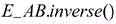
在一些实施例中,上述执行主体可以根据初始目标相机和源相机的相对外参矩阵、上述目标相机的内参矩阵和上述目标相机相对于车体的外参矩阵,利用以下公式,确定上述三维源车道线采样点集合中每个三维源车道线采样点在上述二维目标车道线所在的坐标系中的二维投影点,得到二维投影点集合:In some embodiments, the execution body may determine the three-dimensional source according to the relative extrinsic parameter matrix of the initial target camera and the source camera, the intrinsic parameter matrix of the target camera, and the extrinsic parameter matrix of the target camera relative to the vehicle body, using the following formula The 2D projection point of each 3D source lane line sampling point in the lane line sampling point set in the coordinate system where the above 2D target lane line is located, to obtain the 2D projection point set:

其中,




步骤205,确定二维投影点集合中每个二维投影点到二维目标车道线的距离值,得到距离值集合。Step 205: Determine the distance value from each two-dimensional projected point in the two-dimensional projected point set to the two-dimensional target lane line to obtain a distance value set.
在一些实施例中,上述执行主体可以确定上述二维投影点集合中每个二维投影点到上述二维目标车道线的距离值,得到距离值集合。In some embodiments, the executive body may determine a distance value between each two-dimensional projection point in the two-dimensional projection point set and the two-dimensional target lane line, to obtain a distance value set.
步骤206,响应于确定距离值集合中各个距离值的和大于预设距离值,对二维源车道线和三维源车道线采样点集合进行重新定位处理。
在一些实施例中,上述执行主体可以利用上述初始目标相机和源相机的相对外参矩阵、上述目标相机的内参矩阵、上述目标相机相对于车体的外参矩阵、上述三维源车道线采样点集合和上述二维目标车道线,执行以下车道线定位步骤:In some embodiments, the execution subject may use the relative extrinsic parameter matrix of the initial target camera and the source camera, the intrinsic parameter matrix of the target camera, the extrinsic parameter matrix of the target camera relative to the vehicle body, and the three-dimensional source lane line sampling point. Set and the above two-dimensional target lane lines, perform the following lane line positioning steps:
第一步,对初始目标相机和源相机的相对外参矩阵进行调整。其中,可以根据预设步长调整上述初始目标相机和源相机的相对外参矩阵中的各个参数。The first step is to adjust the relative extrinsic parameter matrices of the initial target camera and the source camera. Wherein, each parameter in the relative extrinsic parameter matrix of the initial target camera and the source camera can be adjusted according to the preset step size.
第二步,根据调整后的初始目标相机和源相机的相对外参矩阵、上述目标相机的内参矩阵和上述目标相机相对于车体的外参矩阵,确定上述三维源车道线采样点集合中每个三维源车道线采样点在上述二维目标车道线所在的坐标系中的二维投影点,得到二维投影点集合。其中,得到二维投影点集合的具体实现方式及所带来的技术效果可以参考步骤204,在此不再赘述。In the second step, according to the adjusted relative extrinsic parameter matrix of the initial target camera and the source camera, the intrinsic parameter matrix of the above-mentioned target camera, and the extrinsic parameter matrix of the above-mentioned target camera relative to the vehicle body, determine each of the three-dimensional source lane line sampling points in the above-mentioned three-dimensional source lane line sampling point set. A set of two-dimensional projection points is obtained from the two-dimensional projection points of the three-dimensional source lane line sampling points in the coordinate system where the two-dimensional target lane line is located. For the specific implementation manner of obtaining the two-dimensional projection point set and the technical effect brought about, reference may be made to step 204, which will not be repeated here.
第三步,确定二维投影点集合中每个二维投影点到上述二维目标车道线的距离,得到距离集合。The third step is to determine the distance between each two-dimensional projected point in the two-dimensional projected point set and the above-mentioned two-dimensional target lane line to obtain a distance set.
第四步,响应于确定距离集合中各个距离的和小于或者等于预设距离阈值,将调整后的初始目标相机和源相机的相对外参矩阵确定目标相对外参矩阵。In the fourth step, in response to determining that the sum of the distances in the distance set is less than or equal to the preset distance threshold, determine the target relative extrinsic parameter matrix from the adjusted relative extrinsic parameter matrix of the initial target camera and the source camera.
在一些实施例的一些可选的实现方式中,上述车道线定位步骤还包括响应于确定距离集合中的各个距离之和大于上述预设距离阈值,继续执行上述车道线定位步骤。In some optional implementations of some embodiments, the above-mentioned lane line locating step further includes continuing to perform the above-mentioned lane line locating step in response to determining that the sum of each distance in the distance set is greater than the above-mentioned preset distance threshold.
可选的,上述执行主体响应于确定上述距离值集合中各个距离值的和大于预设距离值,对上述二维源车道线和上述三维源车道线采样点集合进行重新定位处理,还可以包括以下步骤:Optionally, in response to determining that the sum of each distance value in the above-mentioned distance value set is greater than a preset distance value, the above-mentioned execution body performs relocation processing on the above-mentioned two-dimensional source lane line and the above-mentioned three-dimensional source lane line sampling point set, and may also include: The following steps:
第一步,利用上述目标相对外参矩阵、上述目标相机的内参矩阵和上述目标相机相对于车体的外参矩阵,将上述二维源车道线在上述二维目标车道线所在的坐标系中重新定位,得到重定位二维源车道线。其中,上述重新定位可以是利用上述标相对外参矩阵、上述目标相机的内参矩阵和上述目标相机相对于车体的外参矩阵将上述二维源车道线投影至。二维目标车道线所在的坐标系中In the first step, the above-mentioned two-dimensional source lane line is placed in the coordinate system where the two-dimensional target lane line is located by using the above-mentioned target relative extrinsic parameter matrix, the above-mentioned target camera's internal parameter matrix and the above-mentioned target camera's extrinsic parameter matrix relative to the vehicle body. Reposition to get the repositioned 2D source lane line. Wherein, the repositioning may be to project the two-dimensional source lane line onto the above-mentioned two-dimensional source lane line by using the above-mentioned relative extrinsic parameter matrix, the above-mentioned internal parameter matrix of the target camera, and the above-mentioned extrinsic parameter matrix of the target camera relative to the vehicle body. In the coordinate system where the two-dimensional target lane line is located
第二步,对上述重定位二维源车道线和上述二维目标车道线进行融合,得到车道线识别结果。其中,可以利用图像融合算法对上述重定位二维源车道线和上述二维目标车道线进行融合。上述图像融合算法可以包括单不限于:基于空间域的融合方法和基于变换域的融合方法等。In the second step, the above relocated two-dimensional source lane lines and the above two-dimensional target lane lines are fused to obtain a lane line recognition result. Wherein, an image fusion algorithm may be used to fuse the above-mentioned relocated two-dimensional source lane line and the above-mentioned two-dimensional target lane line. The above-mentioned image fusion algorithms may include, but are not limited to, fusion methods based on spatial domains, fusion methods based on transform domains, and the like.
第三步,将上述车道线识别结果发送至上述目标车辆的显示终端以供显示。In the third step, the above-mentioned lane line recognition result is sent to the display terminal of the above-mentioned target vehicle for display.
本公开的上述各个实施例具有如下有益效果:通过本公开的一些实施例的车道线定位以及识别方法,能够提高车道线识别和定位的灵活性,满足自动驾驶的实时性需求,提高自动驾驶的可靠性和安全性。具体来说,导致车道线识别和定位的灵活较低,难以满足自动驾驶的实时性需求的原因在于:在多张车道线图像之间不具有共视区域时,无法实现对车道线的识别和定位。基于此,本公开的一些实施例的车道线定位以及识别方法,首先,控制目标车辆上的目标相机和源相机分别拍摄车道线图像,得到车道线目标图像和车道线源图像。其中,上述车道线目标图像和上述车道线源图像可以有共视区域,也可以没有共视区域。然后,分别从上述车道线目标图像和上述车道线源图像中识别二维目标车道线和二维源车道线。再然后,响应于确定上述车道线目标图像和上述车道线源图像为同一时刻拍摄的图像,根据上述二维源车道线,生成三维源车道线采样点集合。接着,根据初始目标相机和源相机的相对外参矩阵、上述目标相机的内参矩阵和上述目标相机相对于车体的外参矩阵,确定上述三维源车道线采样点集合中每个三维源车道线采样点在上述二维目标车道线所在的坐标系中的二维投影点,得到二维投影点集合。再接着,确定上述二维投影点集合中每个二维投影点到上述二维目标车道线的距离值,得到距离值集合。由此,可以根据距离值集合确定目标相机和源相机拍摄的车道线目标图像和车道线源图像中车道线之间的定位偏差。最后,响应于确定上述距离值集合中各个距离值的和大于预设距离值,对上述二维源车道线和上述三维源车道线采样点集合进行重新定位处理。由此,在目标相机和源相机拍摄的车道线目标图像和车道线源图像中车道线之间的定位偏差较大时,对上述二维源车道线进行重新定位。从而,统一上述二维目标车道线和上述二维源车道线的定位信息。进而,提高车道线识别和定位的灵活性,满足自动驾驶的实时性需求,提高自动驾驶的可靠性和安全性。The above-mentioned embodiments of the present disclosure have the following beneficial effects: through the lane line positioning and identification methods of some embodiments of the present disclosure, the flexibility of lane line identification and positioning can be improved, the real-time requirements of automatic driving can be met, and the performance of automatic driving can be improved. reliability and security. Specifically, the reason that the flexibility of lane line recognition and positioning is low, and it is difficult to meet the real-time requirements of automatic driving is that: when there is no common viewing area between multiple lane line images, it is impossible to realize the lane line recognition and identification. position. Based on this, in the lane line localization and identification methods of some embodiments of the present disclosure, first, the target camera and the source camera on the target vehicle are controlled to capture lane line images respectively to obtain the lane line target image and the lane line source image. Wherein, the above-mentioned lane line target image and the above-mentioned lane line source image may have a common viewing area, or may not have a common viewing area. Then, the two-dimensional target lane lines and the two-dimensional source lane lines are identified from the above-mentioned lane line target image and the above-mentioned lane line source image, respectively. Then, in response to determining that the lane line target image and the lane line source image are images captured at the same time, a three-dimensional source lane line sampling point set is generated according to the two-dimensional source lane line. Next, according to the relative extrinsic parameter matrix of the initial target camera and the source camera, the intrinsic parameter matrix of the target camera, and the extrinsic parameter matrix of the target camera relative to the vehicle body, determine each three-dimensional source lane line in the three-dimensional source lane line sampling point set The sampling point is a two-dimensional projection point in the coordinate system where the two-dimensional target lane line is located to obtain a two-dimensional projection point set. Next, the distance value between each two-dimensional projection point in the above-mentioned two-dimensional projection point set and the above-mentioned two-dimensional target lane line is determined to obtain a distance value set. Thus, the positioning deviation between the lane line target image captured by the target camera and the source camera and the lane line in the lane line source image can be determined according to the distance value set. Finally, in response to determining that the sum of the distance values in the distance value set is greater than the preset distance value, relocation processing is performed on the two-dimensional source lane line and the three-dimensional source lane line sampling point set. Therefore, when the positioning deviation between the lane lines in the lane line target image captured by the target camera and the source camera and the lane line source image is relatively large, the above-mentioned two-dimensional source lane lines are repositioned. Therefore, the positioning information of the two-dimensional target lane line and the two-dimensional source lane line is unified. Furthermore, it can improve the flexibility of lane line recognition and positioning, meet the real-time requirements of automatic driving, and improve the reliability and safety of automatic driving.
进一步参考图3,其示出了车道线识别及定位方法的另一些实施例的流程300。该车道线识别及定位方法的流程300,包括以下步骤:With further reference to FIG. 3 , a
步骤301,控制目标车辆上的目标相机和源相机分别拍摄车道线图像,得到车道线目标图像和车道线源图像。
步骤302,分别从车道线目标图像和车道线源图像中识别二维目标车道线和二维源车道线。
步骤303,响应于确定车道线目标图像和车道线源图像为同一时刻拍摄的图像,根据二维源车道线,生成三维源车道线采样点集合。
在一些实施例中,步骤301-303的具体实现方式及所带来的技术效果可以参考图2对应的那些实施例中的步骤201-203,在此不再赘述。In some embodiments, for the specific implementation manner of steps 301-303 and the technical effects brought about, reference may be made to steps 201-203 in those embodiments corresponding to FIG. 2, and details are not repeated here.
步骤304,响应于确定车道线目标图像和车道线源图像为不同时刻拍摄的图像,确定车道线目标图像和车道线源图像是否具有共视区域。
在一些实施例中,上述执行主体响应于确定上述车道线目标图像和上述车道线源图像为不同时刻拍摄的图像,确定上述车道线目标图像和上述车道线源图像是否具有共视区域,可以包括以下步骤:In some embodiments, in response to determining that the lane line target image and the lane line source image are images captured at different times, the execution body determines whether the lane line target image and the lane line source image have a common viewing area, which may include: The following steps:
第一步,分别获取上述目标车辆拍摄上述车道线目标图像时的目标位姿,和拍摄上述车道线源图像时的源位姿。The first step is to obtain the target pose of the target vehicle when shooting the lane line target image and the source pose when shooting the lane line source image.
第二步,确定上述目标位姿和上述源位姿之间的相对位姿。其中,可以通过以下公式确定上述相对位姿:In the second step, the relative pose between the target pose and the source pose is determined. Among them, the above relative pose can be determined by the following formula:

其中,


第三步,确定上述二维源车道线在预设范围内的起点和终点,得到源起点和源终点,以及确定上述二维目标车道线在上述预设范围内的起点和终点,得到目标起点和目标终点。其中,上述预设范围可以是20米。上述二维源车道线在预设范围内的起点可以是上述二维源车道线与上述车道线源图像的边界的交点。The third step is to determine the starting point and end point of the two-dimensional source lane line within the preset range, obtain the source starting point and the source end point, and determine the starting point and ending point of the two-dimensional target lane line within the preset range to obtain the target starting point and target destination. Wherein, the above-mentioned preset range may be 20 meters. The starting point of the above-mentioned two-dimensional source lane line within the preset range may be an intersection point of the above-mentioned two-dimensional source lane line and the boundary of the above-mentioned lane line source image.
第四步,根据上述相对位姿和上述初始目标相机和源相机的相对外参矩阵,对上述源起点和上述源终点进行投影,得到投影起点和投影终点。Step 4: Project the source start point and the source end point according to the relative pose and the relative extrinsic parameter matrix of the initial target camera and the source camera to obtain the projection start point and the projection end point.
第五步,响应于确定上述投影起点和\或上述投影终点在上述目标起点和上述目标终点所限定的范围内,确定上述车道线目标图像和上述车道线源图像具有共视区域。The fifth step, in response to determining that the above-mentioned projection starting point and/or the above-mentioned projection end point are within the range defined by the above-mentioned target starting point and the above-mentioned target end point, it is determined that the above-mentioned lane line target image and the above-mentioned lane line source image have a common viewing area.
由此,可以在车道线目标图像和车道线源图像为不同时刻拍摄的图像时,根据车道线目标图像和车道线源图像的共视区域对车道线进行定位。从而,进一步提高车道线识别和定位的灵活性,满足自动驾驶的实时性需求,提高自动驾驶的可靠性和安全性。Therefore, when the lane line target image and the lane line source image are images captured at different times, the lane line can be positioned according to the common viewing area of the lane line target image and the lane line source image. Thereby, the flexibility of lane line recognition and positioning is further improved, the real-time requirements of automatic driving are met, and the reliability and safety of automatic driving are improved.
步骤305,响应于确定车道线目标图像和车道线源图像具有共视区域,根据二维源车道线,生成三维源车道线采样点集合。
在一些实施例中,上述执行主体可以响应于确定上述车道线目标图像和上述车道线源图像具有共视区域,根据上述二维源车道线,生成三维源车道线采样点集合。其中,生成三维源车道线采样点集合的具体实现方式及所带来的技术效果可以参考图2对应的那些实施例中的步骤203,在此不再赘述。In some embodiments, the execution body may, in response to determining that the lane line target image and the lane line source image have a common viewing area, generate a three-dimensional source lane line sampling point set according to the two-dimensional source lane line. The specific implementation manner of generating the three-dimensional source lane line sampling point set and the technical effect brought about may refer to step 203 in those embodiments corresponding to FIG. 2 , and details are not repeated here.
步骤306,根据初始目标相机和源相机的相对外参矩阵、目标相机的内参矩阵和目标相机相对于车体的外参矩阵,确定三维源车道线采样点集合中每个三维源车道线采样点在二维目标车道线所在的坐标系中的二维投影点,得到二维投影点集合。
步骤307,确定二维投影点集合中每个二维投影点到二维目标车道线的距离值,得到距离值集合。Step 307: Determine the distance value from each two-dimensional projected point in the two-dimensional projected point set to the two-dimensional target lane line to obtain a distance value set.
步骤308,响应于确定距离值集合中各个距离值的和大于预设距离值,对二维源车道线和三维源车道线采样点集合进行重新定位处理。
在一些实施例中,步骤306-308的具体实现方式及所带来的技术效果可以参考图2对应的那些实施例中的步骤204-206,在此不再赘述。In some embodiments, for the specific implementation manner of steps 306-308 and the technical effects brought about, reference may be made to steps 204-206 in those embodiments corresponding to FIG. 2, and details are not repeated here.
从图3中可以看出,与图2对应的一些实施例的描述相比,图3对应的一些实施例中的车道线识别及定位方法的流程300体现了在车道线目标图像和车道线源图像为不同时刻拍摄的图像时,对车道线进行定位的步骤。由此,可以在车道线目标图像和车道线源图像为不同时刻拍摄的图像时,根据车道线目标图像和车道线源图像的共视区域对车道线进行定位。从而,进一步提高车道线识别和定位的灵活性,满足自动驾驶的实时性需求,提高自动驾驶的可靠性和安全性。As can be seen from FIG. 3 , compared with the description of some embodiments corresponding to FIG. 2 , the
下面参考图4,其示出了适于用来实现本公开的一些实施例的电子设备400的结构示意图。图4示出的电子设备仅仅是一个示例,不应对本公开的实施例的功能和使用范围带来任何限制。Referring now to FIG. 4 , a schematic structural diagram of an
如图4所示,电子设备400可以包括处理装置(例如中央处理器、图形处理器等)401,其可以根据存储在只读存储器(ROM)402中的程序或者从存储装置408加载到随机访问存储器(RAM)403中的程序而执行各种适当的动作和处理。在RAM 403中,还存储有电子设备400操作所需的各种程序和数据。处理装置401、ROM 402以及RAM 403通过总线404彼此相连。输入/输出(I/O)接口405也连接至总线404。As shown in FIG. 4 , an
通常,以下装置可以连接至I/O接口405:包括例如触摸屏、触摸板、键盘、鼠标、摄像头、麦克风、加速度计、陀螺仪等的输入装置406;包括例如液晶显示器(LCD)、扬声器、振动器等的输出装置407;以及通信装置409。通信装置409可以允许电子设备400与其他设备进行无线或有线通信以交换数据。虽然图4示出了具有各种装置的电子设备400,但是应理解的是,并不要求实施或具备所有示出的装置。可以替代地实施或具备更多或更少的装置。图4中示出的每个方框可以代表一个装置,也可以根据需要代表多个装置。Typically, the following devices may be connected to the I/O interface 405:
特别地,根据本公开的一些实施例,上文参考流程图描述的过程可以被实现为计算机软件程序。例如,本公开的一些实施例包括一种计算机程序产品,其包括承载在计算机可读介质上的计算机程序,该计算机程序包含用于执行流程图所示的方法的程序代码。在这样的一些实施例中,该计算机程序可以通过通信装置409从网络上被下载和安装,或者从存储装置408被安装,或者从ROM 402被安装。在该计算机程序被处理装置401执行时,执行本公开的一些实施例的方法中限定的上述功能。In particular, according to some embodiments of the present disclosure, the processes described above with reference to the flowcharts may be implemented as computer software programs. For example, some embodiments of the present disclosure include a computer program product comprising a computer program carried on a computer-readable medium, the computer program containing program code for performing the method illustrated in the flowchart. In some such embodiments, the computer program may be downloaded and installed from the network via the
需要说明的是,本公开的一些实施例中记载的计算机可读介质可以是计算机可读信号介质或者计算机可读存储介质或者是上述两者的任意组合。计算机可读存储介质例如可以是——但不限于——电、磁、光、电磁、红外线、或半导体的系统、装置或器件,或者任意以上的组合。计算机可读存储介质的更具体的例子可以包括但不限于:具有一个或多个导线的电连接、便携式计算机磁盘、硬盘、随机访问存储器(RAM)、只读存储器(ROM)、可擦式可编程只读存储器(EPROM或闪存)、光纤、便携式紧凑磁盘只读存储器(CD-ROM)、光存储器件、磁存储器件、或者上述的任意合适的组合。在本公开的一些实施例中,计算机可读存储介质可以是任何包含或存储程序的有形介质,该程序可以被指令执行系统、装置或者器件使用或者与其结合使用。而在本公开的一些实施例中,计算机可读信号介质可以包括在基带中或者作为载波一部分传播的数据信号,其中承载了计算机可读的程序代码。这种传播的数据信号可以采用多种形式,包括但不限于电磁信号、光信号或上述的任意合适的组合。计算机可读信号介质还可以是计算机可读存储介质以外的任何计算机可读介质,该计算机可读信号介质可以发送、传播或者传输用于由指令执行系统、装置或者器件使用或者与其结合使用的程序。计算机可读介质上包含的程序代码可以用任何适当的介质传输,包括但不限于:电线、光缆、RF(射频)等等,或者上述的任意合适的组合。It should be noted that the computer-readable medium described in some embodiments of the present disclosure may be a computer-readable signal medium or a computer-readable storage medium, or any combination of the above two. The computer-readable storage medium can be, for example, but not limited to, an electrical, magnetic, optical, electromagnetic, infrared, or semiconductor system, apparatus or device, or a combination of any of the above. More specific examples of computer readable storage media may include, but are not limited to, electrical connections with one or more wires, portable computer disks, hard disks, random access memory (RAM), read only memory (ROM), erasable Programmable read only memory (EPROM or flash memory), optical fiber, portable compact disk read only memory (CD-ROM), optical storage devices, magnetic storage devices, or any suitable combination of the above. In some embodiments of the present disclosure, a computer-readable storage medium can be any tangible medium that contains or stores a program that can be used by or in conjunction with an instruction execution system, apparatus, or device. Rather, in some embodiments of the present disclosure, a computer-readable signal medium may include a data signal propagated in baseband or as part of a carrier wave, carrying computer-readable program code therein. Such propagated data signals may take a variety of forms, including but not limited to electromagnetic signals, optical signals, or any suitable combination of the foregoing. A computer-readable signal medium can also be any computer-readable medium other than a computer-readable storage medium that can transmit, propagate, or transport the program for use by or in connection with the instruction execution system, apparatus, or device . Program code embodied on a computer readable medium may be transmitted using any suitable medium including, but not limited to, electrical wire, optical fiber cable, RF (radio frequency), etc., or any suitable combination of the foregoing.
在一些实施方式中,客户端、服务器可以利用诸如HTTP(HyperText TransferProtocol,超文本传输协议)之类的任何当前已知或未来研发的网络协议进行通信,并且可以与任意形式或介质的数字数据通信(例如,通信网络)互连。通信网络的示例包括局域网(“LAN”),广域网(“WAN”),网际网(例如,互联网)以及端对端网络(例如,ad hoc端对端网络),以及任何当前已知或未来研发的网络。In some embodiments, the client and server can communicate using any currently known or future developed network protocol such as HTTP (HyperText Transfer Protocol), and can communicate with digital data in any form or medium (eg, a communications network) interconnect. Examples of communication networks include local area networks ("LAN"), wide area networks ("WAN"), the Internet (eg, the Internet), and peer-to-peer networks (eg, ad hoc peer-to-peer networks), as well as any currently known or future development network of.
上述计算机可读介质可以是上述电子设备中所包含的;也可以是单独存在,而未装配入该电子设备中。上述计算机可读介质承载有一个或者多个程序,当上述一个或者多个程序被该电子设备执行时,使得该电子设备:控制目标车辆上的目标相机和源相机分别拍摄车道线图像,得到车道线目标图像和车道线源图像;分别从上述车道线目标图像和上述车道线源图像中识别二维目标车道线和二维源车道线;响应于确定上述车道线目标图像和上述车道线源图像为同一时刻拍摄的图像,根据上述二维源车道线,生成三维源车道线采样点集合;根据初始目标相机和源相机的相对外参矩阵、上述目标相机的内参矩阵和上述目标相机相对于车体的外参矩阵,确定上述三维源车道线采样点集合中每个三维源车道线采样点在上述二维目标车道线所在的坐标系中的二维投影点,得到二维投影点集合;确定上述二维投影点集合中每个二维投影点到上述二维目标车道线的距离值,得到距离值集合;响应于确定上述距离值集合中各个距离值的和大于预设距离值,对上述二维源车道线和上述三维源车道线采样点集合进行重新定位处理。The above-mentioned computer-readable medium may be included in the above-mentioned electronic device; or may exist alone without being assembled into the electronic device. The above-mentioned computer-readable medium carries one or more programs, and when the above-mentioned one or more programs are executed by the electronic device, the electronic device: controls the target camera and the source camera on the target vehicle to take images of the lane lines, respectively, to obtain the lane identifying a two-dimensional target lane line and a two-dimensional source lane line from the above-mentioned lane line target image and the above-mentioned lane line source image, respectively; in response to determining the above-mentioned lane line target image and the above-mentioned lane line source image For the images taken at the same time, according to the above-mentioned two-dimensional source lane lines, generate a three-dimensional source lane line sampling point set; The external parameter matrix of the body is used to determine the two-dimensional projection point of each three-dimensional source lane line sampling point in the above-mentioned three-dimensional source lane line sampling point set in the coordinate system where the two-dimensional target lane line is located to obtain a two-dimensional projection point set; determine; The distance value of each two-dimensional projection point in the above-mentioned two-dimensional projection point set to the above-mentioned two-dimensional target lane line, to obtain a distance value set; in response to determining that the sum of each distance value in the above-mentioned distance value set is greater than the preset distance value, the above-mentioned distance value is determined. The two-dimensional source lane line and the above-mentioned three-dimensional source lane line sampling point set are subjected to relocation processing.
可以以一种或多种程序设计语言或其组合来编写用于执行本公开的一些实施例的操作的计算机程序代码,上述程序设计语言包括面向对象的程序设计语言—诸如Java、Smalltalk、C++,还包括常规的过程式程序设计语言—诸如“C”语言或类似的程序设计语言。程序代码可以完全地在用户计算机上执行、部分地在用户计算机上执行、作为一个独立的软件包执行、部分在用户计算机上部分在远程计算机上执行、或者完全在远程计算机或服务器上执行。在涉及远程计算机的情形中,远程计算机可以通过任意种类的网络——包括局域网(LAN)或广域网(WAN)——连接到用户计算机,或者,可以连接到外部计算机(例如利用因特网服务提供商来通过因特网连接)。Computer program code for carrying out operations of some embodiments of the present disclosure may be written in one or more programming languages, including object-oriented programming languages—such as Java, Smalltalk, C++, or a combination thereof, Also included are conventional procedural programming languages - such as the "C" language or similar programming languages. The program code may execute entirely on the user's computer, partly on the user's computer, as a stand-alone software package, partly on the user's computer and partly on a remote computer, or entirely on the remote computer or server. In the case of a remote computer, the remote computer may be connected to the user's computer through any kind of network, including a local area network (LAN) or a wide area network (WAN), or may be connected to an external computer (eg, using an Internet service provider to via an Internet connection).
附图中的流程图和框图,图示了按照本公开各种实施例的系统、方法和计算机程序产品的可能实现的体系架构、功能和操作。在这点上,流程图或框图中的每个方框可以代表一个模块、程序段、或代码的一部分,该模块、程序段、或代码的一部分包含一个或多个用于实现规定的逻辑功能的可执行指令。也应当注意,在有些作为替换的实现中,方框中所标注的功能也可以以不同于附图中所标注的顺序发生。例如,两个接连地表示的方框实际上可以基本并行地执行,它们有时也可以按相反的顺序执行,这依所涉及的功能而定。也要注意的是,框图和/或流程图中的每个方框、以及框图和/或流程图中的方框的组合,可以用执行规定的功能或操作的专用的基于硬件的系统来实现,或者可以用专用硬件与计算机指令的组合来实现。The flowchart and block diagrams in the Figures illustrate the architecture, functionality, and operation of possible implementations of systems, methods and computer program products according to various embodiments of the present disclosure. In this regard, each block in the flowchart or block diagrams may represent a module, segment, or portion of code that contains one or more logical functions for implementing the specified functions executable instructions. It should also be noted that, in some alternative implementations, the functions noted in the blocks may occur out of the order noted in the figures. For example, two blocks shown in succession may, in fact, be executed substantially concurrently, or the blocks may sometimes be executed in the reverse order, depending upon the functionality involved. It is also noted that each block of the block diagrams and/or flowchart illustrations, and combinations of blocks in the block diagrams and/or flowchart illustrations, can be implemented in dedicated hardware-based systems that perform the specified functions or operations , or can be implemented in a combination of dedicated hardware and computer instructions.
本文中以上描述的功能可以至少部分地由一个或多个硬件逻辑部件来执行。例如,非限制性地,可以使用的示范类型的硬件逻辑部件包括:现场可编程门阵列(FPGA)、专用集成电路(ASIC)、专用标准产品(ASSP)、片上系统(SOC)、复杂可编程逻辑设备(CPLD)等等。The functions described herein above may be performed, at least in part, by one or more hardware logic components. For example, without limitation, exemplary types of hardware logic components that may be used include: Field Programmable Gate Arrays (FPGAs), Application Specific Integrated Circuits (ASICs), Application Specific Standard Products (ASSPs), Systems on Chips (SOCs), Complex Programmable Logical Devices (CPLDs) and more.
Claims (6)
Priority Applications (1)
| Application Number | Priority Date | Filing Date | Title |
|---|---|---|---|
| CN202110774983.4A CN113255619B (en) | 2021-07-09 | 2021-07-09 | Lane line recognition and positioning method, electronic device, and computer-readable medium |
Applications Claiming Priority (1)
| Application Number | Priority Date | Filing Date | Title |
|---|---|---|---|
| CN202110774983.4A CN113255619B (en) | 2021-07-09 | 2021-07-09 | Lane line recognition and positioning method, electronic device, and computer-readable medium |
Publications (2)
| Publication Number | Publication Date |
|---|---|
| CN113255619A CN113255619A (en) | 2021-08-13 |
| CN113255619B true CN113255619B (en) | 2021-11-23 |
Family
ID=77190969
Family Applications (1)
| Application Number | Title | Priority Date | Filing Date |
|---|---|---|---|
| CN202110774983.4A Active CN113255619B (en) | 2021-07-09 | 2021-07-09 | Lane line recognition and positioning method, electronic device, and computer-readable medium |
Country Status (1)
| Country | Link |
|---|---|
| CN (1) | CN113255619B (en) |
Cited By (1)
| Publication number | Priority date | Publication date | Assignee | Title |
|---|---|---|---|---|
| JP2026009004A (en) * | 2024-06-28 | 2026-01-19 | 上海安亭地平▲線▼智能交通技▲術▼有限公司 | METHOD AND APPARATUS FOR DETERMINING LANE LINES, COMPUTER-READABLE STORAGE MEDIUM, AND ELECTRONIC DEVICE |
Families Citing this family (6)
| Publication number | Priority date | Publication date | Assignee | Title |
|---|---|---|---|---|
| CN113870600B (en) * | 2021-09-29 | 2022-09-27 | 禾多阡陌科技(北京)有限公司 | Lane line information display method, lane line information display device, electronic device, and computer-readable medium |
| CN113607185B (en) * | 2021-10-08 | 2022-01-04 | 禾多科技(北京)有限公司 | Lane line information display method, lane line information display device, electronic device, and computer-readable medium |
| CN114140538B (en) * | 2021-12-03 | 2022-09-27 | 禾多科技(北京)有限公司 | Vehicle-mounted camera pose adjusting method, device, equipment and computer readable medium |
| CN114863026B (en) * | 2022-05-18 | 2023-04-14 | 禾多科技(北京)有限公司 | Three-dimensional lane line information generation method, device, device and computer readable medium |
| CN115546748B (en) * | 2022-08-31 | 2026-03-31 | 际络科技(上海)有限公司 | Target detection methods, systems, and electronic devices to improve lateral sensing accuracy |
| CN115578706A (en) * | 2022-10-25 | 2023-01-06 | 毫末智行科技有限公司 | Lane line correction method and device, vehicle control unit and readable storage medium |
Family Cites Families (16)
| Publication number | Priority date | Publication date | Assignee | Title |
|---|---|---|---|---|
| CN104217427B (en) * | 2014-08-22 | 2017-03-15 | 南京邮电大学 | Lane line localization method in a kind of Traffic Surveillance Video |
| US20170021863A1 (en) * | 2015-07-20 | 2017-01-26 | Dura Operating, Llc | System and method for verifying road position information for a motor vehicle |
| CN105654060A (en) * | 2016-01-04 | 2016-06-08 | 中海网络科技股份有限公司 | Method for acquiring vehicle speed from road monitoring video |
| CN107578002B (en) * | 2017-08-28 | 2021-01-05 | 沈阳中科创达软件有限公司 | Method, device, equipment and medium for monitoring lane line identification result |
| CN110569704B (en) * | 2019-05-11 | 2022-11-22 | 北京工业大学 | Multi-strategy self-adaptive lane line detection method based on stereoscopic vision |
| CN111753605B (en) * | 2019-06-11 | 2024-08-20 | 北京京东乾石科技有限公司 | Lane line positioning method, lane line positioning device, electronic equipment and readable medium |
| US10891747B1 (en) * | 2019-06-28 | 2021-01-12 | Baidu Usa Llc | Sensor calibration system for autonomous driving vehicles |
| US10997435B2 (en) * | 2019-08-08 | 2021-05-04 | Nvidia Corporation | Leveraging obstacle and lane detections to determine lane assignments for objects in an environment |
| CN111046741A (en) * | 2019-11-19 | 2020-04-21 | 北京汽车股份有限公司 | Method and device for identifying lane line |
| CN111222417A (en) * | 2019-12-24 | 2020-06-02 | 武汉中海庭数据技术有限公司 | Method and device for improving lane line extraction precision based on vehicle-mounted image |
| CN111582079A (en) * | 2020-04-24 | 2020-08-25 | 杭州鸿泉物联网技术股份有限公司 | Lane positioning method and device based on computer vision |
| CN111832536B (en) * | 2020-07-27 | 2024-03-12 | 北京经纬恒润科技股份有限公司 | A lane line detection method and device |
| CN112598762B (en) * | 2020-09-16 | 2021-10-12 | 禾多科技(北京)有限公司 | Three-dimensional lane line information generation method, device, electronic device and medium |
| CN112598731B (en) * | 2020-10-28 | 2021-11-23 | 禾多科技(北京)有限公司 | Vehicle positioning method and device, electronic equipment and computer readable medium |
| CN112284400B (en) * | 2020-12-24 | 2021-03-19 | 腾讯科技(深圳)有限公司 | Vehicle positioning method and device, electronic equipment and computer readable storage medium |
| CN112328731B (en) * | 2021-01-06 | 2021-07-09 | 禾多科技(北京)有限公司 | Vehicle lane-level positioning method, apparatus, electronic device, and computer-readable medium |
-
2021
- 2021-07-09 CN CN202110774983.4A patent/CN113255619B/en active Active
Cited By (1)
| Publication number | Priority date | Publication date | Assignee | Title |
|---|---|---|---|---|
| JP2026009004A (en) * | 2024-06-28 | 2026-01-19 | 上海安亭地平▲線▼智能交通技▲術▼有限公司 | METHOD AND APPARATUS FOR DETERMINING LANE LINES, COMPUTER-READABLE STORAGE MEDIUM, AND ELECTRONIC DEVICE |
Also Published As
| Publication number | Publication date |
|---|---|
| CN113255619A (en) | 2021-08-13 |
Similar Documents
| Publication | Publication Date | Title |
|---|---|---|
| CN113255619B (en) | Lane line recognition and positioning method, electronic device, and computer-readable medium | |
| CN112733820B (en) | Obstacle information generation method, apparatus, electronic device and computer readable medium | |
| CN113607185B (en) | Lane line information display method, lane line information display device, electronic device, and computer-readable medium | |
| CN113869293B (en) | Lane line recognition method and device, electronic equipment and computer readable medium | |
| CN113256742B (en) | Interface presentation method, apparatus, electronic device and computer readable medium | |
| CN115326099B (en) | Local path planning method and device, electronic equipment and computer readable medium | |
| CN113269168B (en) | Obstacle data processing method and device, electronic equipment and computer readable medium | |
| CN114782613A (en) | Image rendering method, device and equipment and storage medium | |
| CN113674357B (en) | Camera external reference calibration method and device, electronic equipment and computer readable medium | |
| CN114399589B (en) | Three-dimensional lane line generation method and device, electronic device and computer readable medium | |
| CN112232451B (en) | Multi-sensor data fusion method, apparatus, electronic device and medium | |
| CN112598731B (en) | Vehicle positioning method and device, electronic equipment and computer readable medium | |
| CN114399588B (en) | Three-dimensional lane line generation method and device, electronic device and computer readable medium | |
| CN112590798A (en) | Method, apparatus, electronic device, and medium for detecting driver state | |
| CN114724115B (en) | Method, device and equipment for generating obstacle positioning information and computer readable medium | |
| CN113392816B (en) | Pavement disease detection method, device, electronic equipment and computer readable medium | |
| CN115817463B (en) | Vehicle obstacle avoidance method, device, electronic equipment and computer readable medium | |
| WO2024174728A1 (en) | Method and system for detecting obstacle in multi-angle aerial view on basis of virtual camera | |
| CN112561990A (en) | Location information generation method, apparatus, device and computer readable medium | |
| CN115619918A (en) | Image rendering method, device, equipment and storage medium | |
| CN113673446B (en) | Image recognition method, device, electronic device and computer readable medium | |
| CN113778078A (en) | Positioning information generation method and device, electronic equipment and computer readable medium | |
| CN116740382B (en) | Obstacle information generation method, device, electronic equipment and computer-readable medium | |
| CN116563818B (en) | Obstacle information generation method, obstacle information generation device, electronic device, and computer-readable medium | |
| CN115808929B (en) | Vehicle simulation obstacle avoidance method, device, electronic device and computer readable medium |
Legal Events
| Date | Code | Title | Description |
|---|---|---|---|
| PB01 | Publication | ||
| PB01 | Publication | ||
| SE01 | Entry into force of request for substantive examination | ||
| SE01 | Entry into force of request for substantive examination | ||
| GR01 | Patent grant | ||
| GR01 | Patent grant | ||
| PE01 | Entry into force of the registration of the contract for pledge of patent right | ||
| PE01 | Entry into force of the registration of the contract for pledge of patent right |
Denomination of invention: Lane line identification and positioning methods, electronic equipment and computer-readable media Effective date of registration: 20230228 Granted publication date: 20211123 Pledgee: Bank of Shanghai Co.,Ltd. Beijing Branch Pledgor: HOLOMATIC TECHNOLOGY (BEIJING) Co.,Ltd. Registration number: Y2023980033668 |
|
| CP03 | Change of name, title or address |
Address after: 201, 202, 301, No. 56-4 Fenghuang South Road, Huadu District, Guangzhou City, Guangdong Province, 510806 Patentee after: Heduo Technology (Guangzhou) Co.,Ltd. Address before: 100099 101-15, 3rd floor, building 9, yard 55, zique Road, Haidian District, Beijing Patentee before: HOLOMATIC TECHNOLOGY (BEIJING) Co.,Ltd. |
|
| CP03 | Change of name, title or address | ||
| PP01 | Preservation of patent right |
Effective date of registration: 20250121 Granted publication date: 20211123 |
|
| PP01 | Preservation of patent right | ||
| PD01 | Discharge of preservation of patent |
Date of cancellation: 20260116 Granted publication date: 20211123 |
|
| PD01 | Discharge of preservation of patent |