CN113253467A - Optical device, in-vehicle system including optical device, and mobile device - Google Patents
Optical device, in-vehicle system including optical device, and mobile device Download PDFInfo
- Publication number
- CN113253467A CN113253467A CN202110166916.4A CN202110166916A CN113253467A CN 113253467 A CN113253467 A CN 113253467A CN 202110166916 A CN202110166916 A CN 202110166916A CN 113253467 A CN113253467 A CN 113253467A
- Authority
- CN
- China
- Prior art keywords
- light
- optical
- illumination light
- prism
- exemplary embodiment
- Prior art date
- Legal status (The legal status is an assumption and is not a legal conclusion. Google has not performed a legal analysis and makes no representation as to the accuracy of the status listed.)
- Pending
Links
- 230000003287 optical effect Effects 0.000 title claims abstract description 193
- 238000005286 illumination Methods 0.000 claims abstract description 143
- 230000014509 gene expression Effects 0.000 claims description 18
- 238000005259 measurement Methods 0.000 description 16
- 230000008859 change Effects 0.000 description 13
- 238000000034 method Methods 0.000 description 12
- 230000007423 decrease Effects 0.000 description 9
- 238000001514 detection method Methods 0.000 description 9
- 239000000463 material Substances 0.000 description 8
- 238000004519 manufacturing process Methods 0.000 description 6
- 238000012545 processing Methods 0.000 description 6
- 239000004065 semiconductor Substances 0.000 description 6
- 238000005304 joining Methods 0.000 description 4
- 230000010355 oscillation Effects 0.000 description 4
- 230000005540 biological transmission Effects 0.000 description 3
- 230000009467 reduction Effects 0.000 description 3
- 230000008439 repair process Effects 0.000 description 3
- 238000002834 transmittance Methods 0.000 description 3
- 230000004304 visual acuity Effects 0.000 description 3
- 239000000853 adhesive Substances 0.000 description 2
- 230000001070 adhesive effect Effects 0.000 description 2
- 238000006243 chemical reaction Methods 0.000 description 2
- 238000010586 diagram Methods 0.000 description 2
- 230000005684 electric field Effects 0.000 description 2
- 230000007613 environmental effect Effects 0.000 description 2
- 238000012986 modification Methods 0.000 description 2
- 230000004048 modification Effects 0.000 description 2
- 230000008569 process Effects 0.000 description 2
- 210000001747 pupil Anatomy 0.000 description 2
- 238000007493 shaping process Methods 0.000 description 2
- 239000000758 substrate Substances 0.000 description 2
- 241000511976 Hoya Species 0.000 description 1
- 238000010521 absorption reaction Methods 0.000 description 1
- 238000013459 approach Methods 0.000 description 1
- 238000005520 cutting process Methods 0.000 description 1
- 230000003247 decreasing effect Effects 0.000 description 1
- 238000009792 diffusion process Methods 0.000 description 1
- 238000006073 displacement reaction Methods 0.000 description 1
- 238000003384 imaging method Methods 0.000 description 1
- 238000007689 inspection Methods 0.000 description 1
- 239000002184 metal Substances 0.000 description 1
- 238000012544 monitoring process Methods 0.000 description 1
- 230000010287 polarization Effects 0.000 description 1
- 230000035945 sensitivity Effects 0.000 description 1
- 230000035939 shock Effects 0.000 description 1
- 238000003860 storage Methods 0.000 description 1
- 239000000126 substance Substances 0.000 description 1
Images




Classifications
-
- G—PHYSICS
- G02—OPTICS
- G02B—OPTICAL ELEMENTS, SYSTEMS OR APPARATUS
- G02B27/00—Optical systems or apparatus not provided for by any of the groups G02B1/00 - G02B26/00, G02B30/00
- G02B27/09—Beam shaping, e.g. changing the cross-sectional area, not otherwise provided for
- G02B27/0927—Systems for changing the beam intensity distribution, e.g. Gaussian to top-hat
-
- B—PERFORMING OPERATIONS; TRANSPORTING
- B60—VEHICLES IN GENERAL
- B60T—VEHICLE BRAKE CONTROL SYSTEMS OR PARTS THEREOF; BRAKE CONTROL SYSTEMS OR PARTS THEREOF, IN GENERAL; ARRANGEMENT OF BRAKING ELEMENTS ON VEHICLES IN GENERAL; PORTABLE DEVICES FOR PREVENTING UNWANTED MOVEMENT OF VEHICLES; VEHICLE MODIFICATIONS TO FACILITATE COOLING OF BRAKES
- B60T7/00—Brake-action initiating means
- B60T7/12—Brake-action initiating means for automatic initiation; for initiation not subject to will of driver or passenger
- B60T7/22—Brake-action initiating means for automatic initiation; for initiation not subject to will of driver or passenger initiated by contact of vehicle, e.g. bumper, with an external object, e.g. another vehicle, or by means of contactless obstacle detectors mounted on the vehicle
-
- B—PERFORMING OPERATIONS; TRANSPORTING
- B60—VEHICLES IN GENERAL
- B60Q—ARRANGEMENT OF SIGNALLING OR LIGHTING DEVICES, THE MOUNTING OR SUPPORTING THEREOF OR CIRCUITS THEREFOR, FOR VEHICLES IN GENERAL
- B60Q9/00—Arrangement or adaptation of signal devices not provided for in one of main groups B60Q1/00 - B60Q7/00, e.g. haptic signalling
- B60Q9/008—Arrangement or adaptation of signal devices not provided for in one of main groups B60Q1/00 - B60Q7/00, e.g. haptic signalling for anti-collision purposes
-
- G—PHYSICS
- G01—MEASURING; TESTING
- G01S—RADIO DIRECTION-FINDING; RADIO NAVIGATION; DETERMINING DISTANCE OR VELOCITY BY USE OF RADIO WAVES; LOCATING OR PRESENCE-DETECTING BY USE OF THE REFLECTION OR RERADIATION OF RADIO WAVES; ANALOGOUS ARRANGEMENTS USING OTHER WAVES
- G01S17/00—Systems using the reflection or reradiation of electromagnetic waves other than radio waves, e.g. lidar systems
- G01S17/02—Systems using the reflection of electromagnetic waves other than radio waves
- G01S17/06—Systems determining position data of a target
- G01S17/08—Systems determining position data of a target for measuring distance only
-
- G—PHYSICS
- G01—MEASURING; TESTING
- G01S—RADIO DIRECTION-FINDING; RADIO NAVIGATION; DETERMINING DISTANCE OR VELOCITY BY USE OF RADIO WAVES; LOCATING OR PRESENCE-DETECTING BY USE OF THE REFLECTION OR RERADIATION OF RADIO WAVES; ANALOGOUS ARRANGEMENTS USING OTHER WAVES
- G01S17/00—Systems using the reflection or reradiation of electromagnetic waves other than radio waves, e.g. lidar systems
- G01S17/88—Lidar systems specially adapted for specific applications
- G01S17/89—Lidar systems specially adapted for specific applications for mapping or imaging
-
- G—PHYSICS
- G01—MEASURING; TESTING
- G01S—RADIO DIRECTION-FINDING; RADIO NAVIGATION; DETERMINING DISTANCE OR VELOCITY BY USE OF RADIO WAVES; LOCATING OR PRESENCE-DETECTING BY USE OF THE REFLECTION OR RERADIATION OF RADIO WAVES; ANALOGOUS ARRANGEMENTS USING OTHER WAVES
- G01S17/00—Systems using the reflection or reradiation of electromagnetic waves other than radio waves, e.g. lidar systems
- G01S17/88—Lidar systems specially adapted for specific applications
- G01S17/93—Lidar systems specially adapted for specific applications for anti-collision purposes
- G01S17/931—Lidar systems specially adapted for specific applications for anti-collision purposes of land vehicles
-
- G—PHYSICS
- G01—MEASURING; TESTING
- G01S—RADIO DIRECTION-FINDING; RADIO NAVIGATION; DETERMINING DISTANCE OR VELOCITY BY USE OF RADIO WAVES; LOCATING OR PRESENCE-DETECTING BY USE OF THE REFLECTION OR RERADIATION OF RADIO WAVES; ANALOGOUS ARRANGEMENTS USING OTHER WAVES
- G01S7/00—Details of systems according to groups G01S13/00, G01S15/00, G01S17/00
- G01S7/48—Details of systems according to groups G01S13/00, G01S15/00, G01S17/00 of systems according to group G01S17/00
- G01S7/481—Constructional features, e.g. arrangements of optical elements
- G01S7/4811—Constructional features, e.g. arrangements of optical elements common to transmitter and receiver
-
- G—PHYSICS
- G01—MEASURING; TESTING
- G01S—RADIO DIRECTION-FINDING; RADIO NAVIGATION; DETERMINING DISTANCE OR VELOCITY BY USE OF RADIO WAVES; LOCATING OR PRESENCE-DETECTING BY USE OF THE REFLECTION OR RERADIATION OF RADIO WAVES; ANALOGOUS ARRANGEMENTS USING OTHER WAVES
- G01S7/00—Details of systems according to groups G01S13/00, G01S15/00, G01S17/00
- G01S7/48—Details of systems according to groups G01S13/00, G01S15/00, G01S17/00 of systems according to group G01S17/00
- G01S7/481—Constructional features, e.g. arrangements of optical elements
- G01S7/4814—Constructional features, e.g. arrangements of optical elements of transmitters alone
-
- G—PHYSICS
- G01—MEASURING; TESTING
- G01S—RADIO DIRECTION-FINDING; RADIO NAVIGATION; DETERMINING DISTANCE OR VELOCITY BY USE OF RADIO WAVES; LOCATING OR PRESENCE-DETECTING BY USE OF THE REFLECTION OR RERADIATION OF RADIO WAVES; ANALOGOUS ARRANGEMENTS USING OTHER WAVES
- G01S7/00—Details of systems according to groups G01S13/00, G01S15/00, G01S17/00
- G01S7/48—Details of systems according to groups G01S13/00, G01S15/00, G01S17/00 of systems according to group G01S17/00
- G01S7/481—Constructional features, e.g. arrangements of optical elements
- G01S7/4817—Constructional features, e.g. arrangements of optical elements relating to scanning
-
- G—PHYSICS
- G02—OPTICS
- G02B—OPTICAL ELEMENTS, SYSTEMS OR APPARATUS
- G02B26/00—Optical devices or arrangements for the control of light using movable or deformable optical elements
- G02B26/08—Optical devices or arrangements for the control of light using movable or deformable optical elements for controlling the direction of light
- G02B26/10—Scanning systems
- G02B26/101—Scanning systems with both horizontal and vertical deflecting means, e.g. raster or XY scanners
-
- G—PHYSICS
- G02—OPTICS
- G02B—OPTICAL ELEMENTS, SYSTEMS OR APPARATUS
- G02B26/00—Optical devices or arrangements for the control of light using movable or deformable optical elements
- G02B26/08—Optical devices or arrangements for the control of light using movable or deformable optical elements for controlling the direction of light
- G02B26/10—Scanning systems
- G02B26/105—Scanning systems with one or more pivoting mirrors or galvano-mirrors
-
- G—PHYSICS
- G02—OPTICS
- G02B—OPTICAL ELEMENTS, SYSTEMS OR APPARATUS
- G02B27/00—Optical systems or apparatus not provided for by any of the groups G02B1/00 - G02B26/00, G02B30/00
- G02B27/10—Beam splitting or combining systems
-
- G—PHYSICS
- G02—OPTICS
- G02B—OPTICAL ELEMENTS, SYSTEMS OR APPARATUS
- G02B27/00—Optical systems or apparatus not provided for by any of the groups G02B1/00 - G02B26/00, G02B30/00
- G02B27/28—Optical systems or apparatus not provided for by any of the groups G02B1/00 - G02B26/00, G02B30/00 for polarising
- G02B27/283—Optical systems or apparatus not provided for by any of the groups G02B1/00 - G02B26/00, G02B30/00 for polarising used for beam splitting or combining
-
- G—PHYSICS
- G02—OPTICS
- G02B—OPTICAL ELEMENTS, SYSTEMS OR APPARATUS
- G02B5/00—Optical elements other than lenses
- G02B5/30—Polarising elements
- G02B5/3025—Polarisers, i.e. arrangements capable of producing a definite output polarisation state from an unpolarised input state
- G02B5/3066—Polarisers, i.e. arrangements capable of producing a definite output polarisation state from an unpolarised input state involving the reflection of light at a particular angle of incidence, e.g. Brewster's angle
-
- G—PHYSICS
- G02—OPTICS
- G02B—OPTICAL ELEMENTS, SYSTEMS OR APPARATUS
- G02B7/00—Mountings, adjusting means, or light-tight connections, for optical elements
-
- G—PHYSICS
- G02—OPTICS
- G02B—OPTICAL ELEMENTS, SYSTEMS OR APPARATUS
- G02B7/00—Mountings, adjusting means, or light-tight connections, for optical elements
- G02B7/18—Mountings, adjusting means, or light-tight connections, for optical elements for prisms; for mirrors
- G02B7/1805—Mountings, adjusting means, or light-tight connections, for optical elements for prisms; for mirrors for prisms
-
- B—PERFORMING OPERATIONS; TRANSPORTING
- B60—VEHICLES IN GENERAL
- B60T—VEHICLE BRAKE CONTROL SYSTEMS OR PARTS THEREOF; BRAKE CONTROL SYSTEMS OR PARTS THEREOF, IN GENERAL; ARRANGEMENT OF BRAKING ELEMENTS ON VEHICLES IN GENERAL; PORTABLE DEVICES FOR PREVENTING UNWANTED MOVEMENT OF VEHICLES; VEHICLE MODIFICATIONS TO FACILITATE COOLING OF BRAKES
- B60T2201/00—Particular use of vehicle brake systems; Special systems using also the brakes; Special software modules within the brake system controller
- B60T2201/02—Active or adaptive cruise control system; Distance control
- B60T2201/022—Collision avoidance systems
-
- B—PERFORMING OPERATIONS; TRANSPORTING
- B60—VEHICLES IN GENERAL
- B60T—VEHICLE BRAKE CONTROL SYSTEMS OR PARTS THEREOF; BRAKE CONTROL SYSTEMS OR PARTS THEREOF, IN GENERAL; ARRANGEMENT OF BRAKING ELEMENTS ON VEHICLES IN GENERAL; PORTABLE DEVICES FOR PREVENTING UNWANTED MOVEMENT OF VEHICLES; VEHICLE MODIFICATIONS TO FACILITATE COOLING OF BRAKES
- B60T2210/00—Detection or estimation of road or environment conditions; Detection or estimation of road shapes
- B60T2210/30—Environment conditions or position therewithin
- B60T2210/32—Vehicle surroundings
-
- G—PHYSICS
- G02—OPTICS
- G02B—OPTICAL ELEMENTS, SYSTEMS OR APPARATUS
- G02B26/00—Optical devices or arrangements for the control of light using movable or deformable optical elements
- G02B26/08—Optical devices or arrangements for the control of light using movable or deformable optical elements for controlling the direction of light
- G02B26/0816—Optical devices or arrangements for the control of light using movable or deformable optical elements for controlling the direction of light by means of one or more reflecting elements
- G02B26/0833—Optical devices or arrangements for the control of light using movable or deformable optical elements for controlling the direction of light by means of one or more reflecting elements the reflecting element being a micromechanical device, e.g. a MEMS mirror, DMD
-
- G—PHYSICS
- G02—OPTICS
- G02B—OPTICAL ELEMENTS, SYSTEMS OR APPARATUS
- G02B27/00—Optical systems or apparatus not provided for by any of the groups G02B1/00 - G02B26/00, G02B30/00
- G02B27/09—Beam shaping, e.g. changing the cross-sectional area, not otherwise provided for
- G02B27/0938—Using specific optical elements
- G02B27/095—Refractive optical elements
- G02B27/0972—Prisms
Landscapes
- Physics & Mathematics (AREA)
- Engineering & Computer Science (AREA)
- General Physics & Mathematics (AREA)
- Optics & Photonics (AREA)
- Remote Sensing (AREA)
- Radar, Positioning & Navigation (AREA)
- Computer Networks & Wireless Communication (AREA)
- Electromagnetism (AREA)
- Mechanical Engineering (AREA)
- Transportation (AREA)
- Human Computer Interaction (AREA)
- Optical Radar Systems And Details Thereof (AREA)
- Measurement Of Optical Distance (AREA)
- Regulating Braking Force (AREA)
- Traffic Control Systems (AREA)
Abstract
Disclosed are an optical device, an in-vehicle system including the optical device, and a mobile device. The optical device includes: a deflection unit configured to deflect the illumination light from the light source to scan the object and to deflect the reflected light from the object; and a light guide unit configured to guide the illumination light from the light source to the deflection unit and guide the reflected light from the deflection unit to the light receiving element. The light guide unit includes a first optical element that changes a diameter of the illumination light from the light source, a second optical element that includes a pass-through region through which the illumination light from the first optical element passes and a reflection region that reflects the reflection light from the deflection unit, and at least one fixing member that fixes the first optical element and the second optical element to each other.
Description
Technical Field
The present disclosure relates to an optical device that receives reflected light from an illuminated object to detect the object.
Background
Known distance measuring devices that measure the distance to an object scan the object by deflecting the illumination light from the light source via a deflection unit, and then calculate the distance to the object based on the duration until the reflected light is received from the object and the phase of the reflected light.
Japanese patent application laid-open No.2012-68350 discusses a distance measuring device including a prism that reflects either one of illumination light or reflected light on an inner surface and the other on an outer surface to guide the illumination light and the reflected light to a deflection unit and a light receiving element, respectively.
The angle of expansion of illumination light emitted from a typical light source used in a distance measuring apparatus is different between the horizontal direction and the vertical direction. For good distance measurement accuracy, the illumination light is shaped. However, it is difficult to shape the illumination light using the prism whose outer surface is used to reflect the illumination light as discussed in japanese patent application laid-open No. 2012-68350.
On the other hand, although the illumination light can be shaped by the prism whose inner surface is used to reflect the illumination light discussed in japanese patent application laid-open No.2012-68350, it is very difficult to form both the transmission region and the reflection region on the outer surface of the prism of a complicated shape.
Disclosure of Invention
The present disclosure relates to providing an optical device that is easily manufactured and well shapes illumination light.
According to an aspect of the present invention, an optical apparatus includes: a deflection unit configured to deflect the illumination light from the light source to scan the object and to deflect the reflected light from the object; and a light guide unit configured to guide the illumination light from the light source to the deflection unit and guide the reflected light from the deflection unit to the light receiving element. The light guide unit includes a first optical element that changes a diameter of the illumination light from the light source, a second optical element that includes a pass-through region through which the illumination light from the first optical element passes and a reflection region that reflects the reflection light from the deflection unit, and at least one fixing member that fixes the first optical element and the second optical element to each other.
Further features of the invention will become apparent from the following description of exemplary embodiments with reference to the attached drawings.
Drawings
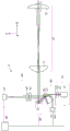
Fig. 1 schematically illustrates main portions of an optical apparatus according to a first exemplary embodiment.
Fig. 2A and 2B illustrate optical paths of illumination light and reflected light, respectively, in the optical device according to the first exemplary embodiment.
Fig. 3 schematically illustrates a general semiconductor laser apparatus.
Fig. 4A and 4B schematically illustrate main portions of a light guide unit according to a first exemplary embodiment.
Fig. 5 illustrates a relationship between an incident angle of P-polarized light with respect to a light guide unit and a reflectance according to the first exemplary embodiment.
Fig. 6 schematically illustrates main portions of an optical apparatus according to a second exemplary embodiment.
Fig. 7A and 7B schematically illustrate main portions of a light guide unit according to a second exemplary embodiment.
Fig. 8 schematically illustrates a main part of an optical apparatus according to a third exemplary embodiment.
Fig. 9A and 9B schematically illustrate a main portion of a light guide unit according to a third exemplary embodiment.
Fig. 10 schematically illustrates a main part of an optical apparatus according to a fourth exemplary embodiment.
Fig. 11A and 11B schematically illustrate a main portion of a light guide unit according to a fifth exemplary embodiment.
FIG. 12 illustrates a functional block diagram of an in-vehicle system according to another exemplary embodiment.
Fig. 13 schematically illustrates a vehicle (mobile device) according to the present exemplary embodiment.
Fig. 14 is a flowchart illustrating an operation example of the in-vehicle system according to the present exemplary embodiment.
Detailed Description
Hereinafter, exemplary embodiments of the present invention will be described with reference to the accompanying drawings. For purposes of illustration, each of the figures may be illustrated at a different scale than actual scale. In each drawing, like reference numerals refer to like components, and redundant description thereof will be omitted.
Fig. 1 schematically illustrates a main part of an optical apparatus 1 in a cross section including an optical axis (YZ cross section) according to a first exemplary embodiment of the present invention. The optical device 1 includes a light source unit 10, a light guiding unit (beam splitting unit) 20, a deflecting unit 30, a light receiving unit (first light receiving unit) 40, a light receiving unit (second light receiving unit) 50 for a light source, and a control unit 60. Fig. 2A and 2B illustrate optical paths in the optical apparatus 1. Fig. 2A illustrates an optical path (illumination optical path) along which illumination light from the light source unit 10 travels toward the object 100, and fig. 2B illustrates an optical path (light reception optical path) along which reflected light from the object 100 travels toward the light reception unit 40.
The optical apparatus 1 functions as a detection apparatus (imaging apparatus) that detects (captures) the object 100, or as a distance measurement apparatus that acquires a distance (distance information) to the object 100 by receiving reflected light from the object 100. The optical device 1 according to the present exemplary embodiment employs a technique called light detection and ranging (LiDAR) to calculate a distance to the object 100 based on a duration until the optical device 1 receives reflected light from the object 100 and a phase of the reflected light.
The light source unit 10 includes a light source 11, an optical element 12, and an aperture 13. The light source 11 may be a semiconductor laser device having high energy concentration and directivity. For example, in the case where the optical apparatus 1 is an in-vehicle system (described below), the object 100 may include a human body. Therefore, the light source 11 emits infrared light having little influence on human eyes. The illumination light emitted by the light source 11 according to the present exemplary embodiment has a wavelength of 905nm in the near-infrared region.
Fig. 3 schematically illustrates a general semiconductor laser apparatus and a light beam emitted therefrom. As illustrated in fig. 3, the active layer 111 of the semiconductor laser device as the light source 11 emits a divergent light beam having an elliptical shape in an xy cross section parallel to the light emitting surface of the active layer 111. If the semiconductor laser light 11 is a linearly polarized light type, the polarization direction of the light beam (oscillation direction of the electric field) is parallel to the upper and lower surfaces of the active layer 111, i.e., in the direction in the zx cross section.
The optical element 12 has a function of changing the convergence of the illumination light emitted from the light source 11. The optical element 12 according to the present exemplary embodiment is a collimator lens (light condensing element) that changes (collimates) a divergent light beam emitted from the light source 11 into a parallel light beam. In this case, the parallel light beam includes not only a strictly parallel light beam but also a nearly parallel light beam such as a weakly divergent light beam and a weakly convergent light beam.
The diaphragm 13, which is a light shielding member provided with an opening, determines a beam diameter (beam width) by narrowing illumination light from the optical element 12. The aperture shape of the diaphragm 13 according to the present exemplary embodiment is an ellipse corresponding to the shape of the illumination light. However, the opening shape is not limited thereto, and may be other than an ellipse. The aperture diameter of the diaphragm 13 according to the present exemplary embodiment is 1.50mm in the X-axis direction (long axis direction) and 0.75mm in the Z-axis direction (short axis direction).
The light guide unit 20 is a light guide member that forms an illumination light path and a light receiving light path as illustrated in fig. 2A and 2B, respectively. The light guide unit 20 guides the illumination light from the light source unit 10 to the deflection unit 30, and guides the reflected light from the deflection unit 30 to the light receiving unit 40. The light guiding unit 20 includes a prism (first optical element) 21 and a beam splitting element (second optical element) 22. The prism 21 changes the diameter of the illumination light from the light source unit 10. The beam splitting element 22 includes a passing region 2221 through which the illumination light from the prism 21 passes and a reflecting region 2222 that reflects the reflected light from the deflection unit 30.
The materials of the prism 21 and the beam splitting element 22 each have a sufficiently high transmittance with respect to the wavelength of the illumination light. More specifically, the materials each have a refractive index of 1.70 or higher with respect to a wavelength of 905 nm. The materials of the prism 21 and the beam splitting element 22 according to the present exemplary embodiment are each S-LAH92 provided by OHARA corporation having a refractive index of 1.871 with respect to a wavelength of 905 nm. The materials of prism 21 and beam splitting element 22 may be different from each other.
Fig. 4A and 4B schematically illustrate main portions of the light guide unit 20 according to the present exemplary embodiment. The prism 21 and the beam splitting element 22 each have a plurality of optical surfaces that transmit and reflect light beams. More specifically, prism 21 has first surface 211, second surface 212, and third surface 213, and beam splitting element 22 has first surface 221 and second surface 222. Fig. 4A illustrates a section (YZ section) perpendicular to each optical surface of the light guide unit 20, and fig. 4B illustrates the first surface 221 and the second surface 222 of the beam splitting element 22 viewed from the normal direction. According to the present exemplary embodiment, in the YZ cross section, an angle α formed between the first surface 211 and the second surface 212 of the prism 211Is 41.0 degrees, and forms an angle alpha between the first surface 211 and the third surface 213 of the prism 212At 78.4 degrees.
The first surface 211 of the prism 21 is an optical surface (light incident surface) on which the illumination light from the light source unit 10 is incident, and the second surface 212 of the prism 21 is an optical surface (light emitting surface) from which the illumination light from the first surface 211 is emitted. As described above, since the opening of the diaphragm 13 is elliptical, the light incident region (passing region) 2111 of the illumination light on the first surface 211 is formed into an elliptical shape. The first surface 211 includes a total reflection region 2112 in a region other than a light incident region 2111 of illumination light from the light source unit 10. The total reflection region 2112 totally reflects the light reflected by the second surface 212 of the prism 21 and each optical surface of the beam splitting element 22 to guide the light to the third surface 213 of the prism 21. An anti-reflection film may be disposed at the light incident region 2111 to reduce reflectance to improve transmittance, and a reflection film may be disposed at the total reflection region 2112.
The first surface 221 of the beam splitting element 22 is an optical surface (light incident surface) on which the illumination light from the second surface 212 of the prism 21 is incident. The second surface 222 of the beam splitting element 22 is an optical surface (light emitting surface and reflection surface) having a passing region 2221 that transmits the illumination light from the first surface 221 and a reflection region 2222 that reflects the reflection light from the deflection unit 30. The pass-through area 2221 according to the present exemplary embodiment is a transmission area of an elliptical shape that transmits illumination light. However, the configuration is not limited thereto.
For example, the beam splitting element 22 may be provided with an aperture that is used as the pass-through region 2221. If the light guide unit 20 shapes the illumination light such that the cross-section thereof has a shape other than an ellipse (e.g., a circle), the passing area 2221 may thus have a shape other than an ellipse (e.g., a circle). The pass-through area 2221 may be provided with an antireflection film. The reflective area 2222 according to the present exemplary embodiment is provided with a metal or dielectric reflective film (reflective layer). An absorption layer that absorbs light from the prism 21 is provided at the bottom (bottom layer) of the reflection film.
The illumination light that has passed through the opening of the diaphragm 13 enters the prism 21 from the first surface 211 of the prism 21, penetrates the second surface 212, and travels to the beam splitting element 22. As described above, the present exemplary embodiment is configured to allow illumination light to enter the prism 21, and then guide the light to the deflection unit 30. This makes it possible to shape the illumination light by refraction at the first surface 211 and the second surface 212 which are not parallel to each other. Therefore, the optical device 1 provides good distance measurement accuracy (detection accuracy) even if the divergent angle (divergence angle) of the illumination light from the light source unit 10 is different between the X direction and the Z direction.
The following assumes a case where the illumination light does not penetrate the prism 21 but is reflected off the outer surface of the prism 21 and then guided to the deflection unit 30. In this case, the illumination light from the light source unit 10 travels to the deflection unit 30 only via the outer surface of the prism 21. In this case, in order to shape the illumination light, the outer surface of the prism 21 is an aspherical (deformed) surface. In this configuration, the reflected light from the object 100 is also incident on the outer surface in which the aspherical surface affects the reflected light, so that it is difficult to obtain good distance measurement accuracy.
Alternatively, a conceivable method is to shape the illumination light by placing another optical element in the illumination light path between the light guide unit 20 and the deflection unit 30. However, this method leads to an increase in the number of parts in the optical device 1, resulting in an increase in the complexity and size of the entire device and an increase in the difficulty of assembly and adjustment of the device. Therefore, in order to obtain good distance measurement accuracy while achieving simplicity and compactness of the optical device 1, as in the present exemplary embodiment, the illumination light enters the prism 21 and is guided to the deflection unit 30 via the plurality of optical surfaces of the prism 21.
In the present exemplary embodiment, the illumination light that has entered the prism 21 from the first surface 211 is directly guided to the second surface 212 without traveling via other surfaces. This configuration enables shaping of the illumination light by using the minimum number of optical surfaces of the prism 21 (i.e., only via the first surface 211 and the second surface 212). This reduces the likelihood that the local illumination light is scattered by scratches and foreign objects on the optical surface, thereby producing unwanted light that will enter the beam splitting element 22.
According to the present exemplary embodiment, the light guide unit 20 includes a plurality of optical elements. More specifically, the light guiding unit 20 is constituted by a prism 21 that changes the diameter of the illumination light and a beam splitting element 22 that guides the illumination light to the deflection unit 30 and guides the reflected light from the deflection unit 30 to the light receiving unit 40. As described above, the first surface 211 and the second surface 212 of the prism 21 are not parallel to each other to change the diameter of the illumination light. It is very difficult to provide the pass area and the reflection area with high accuracy on the outer surface of the prism 21 of such a complicated shape.
On the other hand, the beam splitting element 22 that does not change the diameter of the illumination light may be formed into a simple shape such as a parallel plate. The first surface 221 and the second surface 222 of the beam splitting element 22 according to the present exemplary embodiment are parallel to each other, and the beam splitting element 22 is a flat plate. The pass-through region and the reflection region can be easily provided with high accuracy to the outer surface of such a simple-shaped beam splitting element. In addition, a plurality of beam splitting elements 22 can be easily manufactured at the same time. For example, the manufacturing cost can be reduced by providing the pass area and the reflection area on the substrate and cutting out the plurality of beam splitting elements 22 from the substrate.
In addition, the prism 21 and the beam splitting element 22 according to the present exemplary embodiment are "fixed" (integrally held) to each other by a fixing member 29. The prism 21 and the beam splitting element 22 fixed to each other allow a higher accuracy of positioning of the prism 21 and the beam splitting element 22 in the mounting of the light guiding unit 20 during the manufacturing process of the optical device 1. In addition, this configuration reduces displacement of the individual members due to vibration or shock. According to the present exemplary embodiment, the second surface 212 of the prism 21 and the first surface 221 of the beam splitting element 22 are joined by the fixing member 29 as a joining member (adhesive), but the configuration of the fixing member 29 is not limited thereto.
For example, the prism 21 and the beam splitting element 22 may be bonded to each other with an adhesive applied to the outer surfaces of the two members, or may be fixed by simultaneously clamping the outer surfaces of the two members with a clamping member. In order to repair and repair the light guide unit 20, the prism 21 and the beam splitting element 22 may be separately fixed to each other. In addition, the prism 21 and the beam splitting element 22 may be fixed to each other such that the relative position between the two members is variable. For example, the prism 21 and the beam splitting element 22 may be fixed to each other by using a housing member that can accommodate both the prism 21 and the beam splitting element 22 or a shape-variable joining member (e.g., an elastic joining member) thereof.
The fixing member 29 fixes the prism 21 and the beam splitting element 22 outside the passage area of the illumination light. If the fixing member 29 is partially or entirely located in or above the passage area of the illumination light, the optical device 1 may have poor optical performance because the properties of the fixing member 29 change with environmental changes (temperature and humidity changes) or with time. For example, if the fixing member 29 as the joining member becomes turbid (clouded) with environmental changes or with time, the object 100 may be insufficiently illuminated due to a decrease in transmittance of the fixing member 29 and/or diffusion of local illumination light in the fixing member 29. Further, the illumination light (undesired light) diffused in the fixing member 29 may enter the light receiving unit 40.
As described above, providing the fixing member 29 on the region other than the passage region 2221 of the illumination light makes it possible to prevent the optical performance from being affected by the change in the properties of the fixing member 29. In the present exemplary embodiment, as illustrated in fig. 4B, the fixing members 29 are provided at positions on the first surface 221 of the beam splitting element 22 other than the passage area 2221 of the illumination light, more specifically, at the four corners of the first surface 221. The arrangement of the fixing member 29 is not limited to the arrangement illustrated in fig. 4B as long as the fixing member 29 is provided at a portion other than the passage area 2221 of the illumination light. However, in order to stably fix the prism 21 and the beam splitting element 22, fixing members 29 are provided at least three positions on the first surface 221. For more stability, as in the preferred exemplary embodiment, the fixing members 29 are disposed at four positions on the first surface 221.
The position where the prism 21 and the beam splitting element 22 are bonded to the outside of the passage area 2221 of the illumination light creates a gap (pitch) between the second surface 212 of the prism 21 and the first surface 221 of the beam splitting element 22 in the passage area of the illumination light. In order to reduce the size of the light guide unit 20 and improve light utilization efficiency, the distance between the second surface 212 and the first surface 221 is minimized. More specifically, the light guiding unit 20 satisfies the following conditional expression (1):
t<1.0mm (1)
where t is the distance between prism 21 and beam splitting element 22, i.e., the distance between second surface 212 and first surface 221.
If the distance t exceeds the upper limit represented by the conditional expression (1), the size of the light guide unit 20 may increase, and/or the light utilization efficiency of the light guide unit 20 may decrease due to accidental reflection or reduction in the amount of illumination light between the second surface 212 and the first surface 221. According to the present exemplary embodiment, the distance t is 8 μm, and conditional expression (1) is satisfied. In addition, in order to further reduce the size of the light guide unit 20 and/or to further reduce a decrease in the light use efficiency of the light guide unit 20, the following conditional expressions (1a) and (1b) are satisfied in order:
t<0.1mm (1a)
t<0.05mm (1b)
the in-vehicle system (described below) detects an object existing in a range of about 1m (short distance) to about 300m (long distance) from the optical apparatus 1 as the object 100. However, as the distance from the optical apparatus 1 to the subject 100 increases, the intensity of the reflected light (signal light) from the subject 100 decreases. For example, if the distance from the optical device 1 to the object 100 is increased by a factor of 10, the intensity of the reflected light received by the optical device 1 is decreased by a factor of about 1/100.
The accuracy of the measurement of the distance of the object 100, especially at long distances, may be significantly affected by the undesired light as described above. For example, a high ratio of the undesired light to the signal light received by the light receiving unit 40 hinders the discrimination between the signal light and the undesired light, resulting in a great decrease in the distance measurement accuracy. On the one hand, a conceivable method is to increase the amount of illumination light (output of the light source 11) as the distance to the subject 100 increases, resulting in an increase in the influence of the subject 100 on the human eye.
On the other hand, the optical apparatus 1 having a simple configuration according to the present exemplary embodiment reduces the occurrence of undesired light without increasing the amount of illumination light, thus providing good distance measurement accuracy. In addition to this, the optical apparatus 1 according to the present exemplary embodiment can acquire distance information about the object 100 with high accuracy even in the case where an infrared sensor having lower sensitivity than a visible light sensor is used as the light receiving unit 40.
As described above, the prism 21 is configured to change (vary) the diameter of the illumination light from the light source unit 10. In the present exemplary embodiment, when the illumination light passes through the first surface 211 and the second surface 212, the diameter of the illumination light in the YZ section is enlarged by refraction. More specifically, in the YZ cross section, the diameter of the illumination light emitted from the passing region 2221 is larger than the diameter of the illumination light incident on the first surface 211.
Therefore, the expansion angle of the illumination light can be reduced by increasing the diameter of the illumination light, thereby providing sufficient illumination and resolving power even if the object 100 is present at a far distance. In the present exemplary embodiment, only the light beam diameter in the YZ section is enlarged according to the elliptical illumination light from the light source unit 10, but the method is not limited to this configuration. Depending on the shape of the illumination light and given detection information, the beam diameter may be reduced in the YZ section or changed in a section perpendicular to the YZ section.
When in the YZ section, the diameter of the illumination light incident on the first surface 211 of the prism 21 (the diameter of the diaphragm 13) is represented by h1The diameter of the illumination light emitted from the second surface 212 of the prism 21 is represented by h2Indicating that the incident angle of the illumination light with respect to the first surface 211 of the prism 21 is represented by θ1Degree, and the refraction angle of the illumination light with respect to the first surface 211 is represented by θ2Degree, the angle of incidence of the illumination light with respect to the second surface 211 of the prism 21 is represented by θ3Degree and the angle of refraction of the illumination light relative to the second surface 212 is represented by θ4When degree is expressed, based on Snell's law (Snell's law), the following relationship expressed by expression (2) holds:
h2/h1=(cosθ2*cosθ4)/(cosθ1*cosθ3) (2)
when the incident angle theta is relative to the first surface 211 of the prism 211Greater than the refraction angle theta with respect to the second surface 212 of the prism 214When, the values on both sides of the expression (2) are larger than 1. This means that when the values of both sides of expression (2) are larger than 1, the diameter of the illumination light is enlarged by the prism 21. In the present exemplary embodiment, h1=0.75mm、h2=1.425mm、θ164.3 degrees, theta2Theta 28.8 degree312.2 degrees and θ423.3 degrees, and the values of both sides of expression (2) are 1.90, which indicates that the diameter of the illumination light is enlarged.
The deflection unit 30 is a member that deflects the illumination light from the light guide unit 20 to scan the object 100 and deflects the reflected light from the object 100 to guide the reflected light to the light guide unit 20. The deflection unit 30 according to the present exemplary embodiment includes a single driven mirror (movable mirror) 31. The driving mirror 31 can swing about at least two axes (2-axis driving mirror) to enable two-dimensional scanning of the object 100. For example, a galvanometer mirror or a Micro Electro Mechanical System (MEMS) mirror may be employed as the driving mirror 31. The driving mirror 31 according to the present exemplary embodiment is a MEMS mirror having a rocking angle of ± 15 degrees about the X axis and the Y axis and a rocking frequency of 1 kHz.
The light receiving unit (light receiving unit for distance measurement) 40 includes an optical filter 41, an optical element 42, and a light receiving element (light receiving element for distance measurement) 43. The filter 41 is a member that transmits only desired light and blocks (absorbs) other undesired light. The optical filter 41 according to the present exemplary embodiment is a band-pass filter that transmits only light in a wavelength band corresponding to the illumination light emitted from the light source 11. The optical element 42 is a condenser lens that condenses the light passing through the filter 41 onto the light receiving surface of the light receiving element 43. The configurations of the optical filter 41 and the optical element 42 are not limited to those according to the present exemplary embodiment. For example, the two members may be disposed in reverse order, and a plurality of filters 41 and a plurality of optical elements 42 may be disposed.
The light receiving element (first light receiving element) 43 is an element (sensor) that receives light from the optical element 42, photoelectrically converts the light into a signal, and outputs the signal. The light receiving element 43 may be formed of a Photodiode (PD), an Avalanche Photodiode (APD), or a Single Photon Avalanche Diode (SPAD). The light reflected from the object 100 illuminated by the illumination light is deflected by the deflection unit 30 and reflected off the reflection area 2222 of the beam splitting element 22, and then enters the light receiving element 43 through the optical filter 41 and the optical element 42.
The local illumination light from the first surface 211 of the prism 21 does not penetrate the second surface 212 of the prism 21 and each optical surface of the beam splitting element 22, but is reflected from the second surface 212 of the prism 21 and each optical surface of the beam splitting element 22. This reflection occurs regardless of the presence of the antireflection film in the pass area 2221. Fig. 4A illustrates only light reflected off of the pass area 2221 of the beam splitting element 22. The light reflected from the passing region 2221 is totally reflected off the total reflection region 2112 on the first surface 211 of the prism 21, exits from the third surface 213 of the prism 21, and then enters the light receiving unit 50 for a light source.
The light receiving unit 50 for a light source includes a light receiving element (second light receiving element) 51 for a light source that photoelectrically converts the illumination light from the light source 11 into a signal and then outputs the signal. For example, a sensor similar to the light receiving element 43 may be used as the light receiving element 51 for the light source. The light receiving unit 50 for a light source may include an optical element (filter or lens) that guides the light from the prism 21 to a light receiving surface of the light receiving element 51 for a light source.
The control unit 60 controls the light source 11, the driving mirror 31, the light receiving element 43, and the light receiving element 51 for the light source. The control unit 60 is, for example, a processing unit (processor) such as a Central Processing Unit (CPU) or a computing unit (computer) including the processing unit. The control unit 60 independently drives the light source 11 and the driving mirror 31 at a predetermined driving voltage and a predetermined driving frequency, and controls the output (the amount of illumination light) of the light source 11 based on a signal from the light receiving element 51 for the light source. For example, the control unit 60 controls the light source 11 to change illumination light into pulsed light, and performs intensity modulation on the illumination light to generate signal light.
The control unit 60 may acquire distance information about the object 100 based on a time period from a time when the light source 11 emits illumination light (illumination time) until a time when the light receiving element 43 receives reflected light from the object 100 (light receiving time). In this case, the control unit 60 may acquire the signal from the light receiving element 43 at a specific frequency. The control unit 60 may acquire the distance information not based on the duration until the reflected light from the object 100 is received but based on the phase of the reflected light from the object 100. More specifically, the control unit 60 may find a difference (phase difference) between the phase of the signal of the light source 11 and the phase of the signal output from the light receiving element 43, and then multiply the phase difference by the speed of light to acquire distance information about the object 100.
The optical device 1, which is a LiDAR-based distance measuring device, recognizes an object 100 such as a vehicle, a passenger, or an obstacle, and is adapted to control an on-vehicle system of a vehicle provided with the on-vehicle system based on distance information about the object 100. LiDAR may be compatible with either coaxial or non-coaxial systems. In the coaxial system, the optical axes of the light source unit 10 and the light receiving unit 40 partially coincide with each other. In non-coaxial systems, the optical axes do not coincide with each other. The optical device 1 according to the present exemplary embodiment includes the light guiding unit 20 that reduces the size of the entire device using a coaxial system.
In the present exemplary embodiment, the traveling direction of the illumination light incident on the incidence region 2111 is parallel to the traveling direction of the reflected light reflected by the reflection region 2222, which means that the traveling direction is parallel to the Y direction. More specifically, the light source unit 10 and the light receiving unit 40 according to the present exemplary embodiment are disposed such that the respective optical axes are parallel to each other. This arrangement achieves downsizing of the device.
The light source 11 is disposed such that the X axis illustrated in fig. 3 coincides with the Z axis illustrated in fig. 1, and the y axis illustrated in fig. 3 coincides with the X axis illustrated in fig. 1. The disposition of the light source 11 enables the illumination light incident on the incident region 2111 of the first surface 211 to be changed into P-polarized light whose electric field oscillates in YZ cross section.
Fig. 5 illustrates a relationship between an incident angle of P-polarized light with respect to the first surface 211 and a reflectance according to the present exemplary embodiment. As the incident angle with respect to the first surface 211 increases from 0 degrees, the reflectance of the P-polarized light with respect to the first surface 211 decreases. The reflectance once reaches 0 and then increases. The angle of incidence at which the reflectance of P-polarized light is 0 is called Brewster's angle. Brewster angle thetaBExpressed by the following expression (3):
θB=tan-1(N'/N) (3)
where N is the refractive index of the P-polarized light with respect to the entrance medium and N' is the refractive index with respect to the light exit medium.
The illumination light is made to approach Brewster's angle θ with respect to the first surface 211BThe incident angle of (a) allows the reflectance of the light incident region 2111 on the first surface 211 to be reduced without using an antireflection film. This makes it possible to cause the illumination light to enter the prism 21 with high efficiency in a simple configuration. In this case, the prism 21 satisfies the following conditional expression (4):
-10<θB-θ1<10 (4)
according to the present exemplary embodiment, the brewster angle of the material of the prism 21 is 61.9 degrees, thereby obtaining θ satisfying the conditional expression (4)B-θ12.4 degrees. In addition, in order to obtain a lower reflectance value, the following conditional expressions (4a) and (4b) are satisfied in order:
-8.5<θB-θ1<8.5 (4a)
-7.5<θB-θ1<7.5 (4b)
the optical device 1 according to the present exemplary embodiment enables facilitation of manufacturing and good shaping of illumination light.
A second exemplary embodiment will be described. Fig. 6 schematically illustrates a main part of the optical apparatus 2 in a cross section (YZ cross section) having an optical axis of the optical apparatus 2 according to a second exemplary embodiment of the present invention. The optical device 2 according to the present exemplary embodiment differs from the optical device 1 according to the first exemplary embodiment in the configuration of the light guide unit 20, the disposition of the light source unit 10, and the disposition of the light receiving unit 50 for the light source. Other configurations are similar to those of the optical apparatus 1 according to the first exemplary embodiment, and redundant description thereof will be omitted.
The light guide unit 20 according to the present exemplary embodiment includes a prism 23, a beam splitting element 24, and a fixing member 29 that fixes the two members. The shapes of the prism 23 and the beam splitting element 24 are different from those according to the first exemplary embodiment. The prism 23 and the beam splitting element 24 according to the present exemplary embodiment are made of TAFD55 provided by HOYA corporation having a refractive index of 1.972 with respect to a wavelength of 905 nm. The optical device 2 according to the present exemplary embodiment differs from the optical device 1 according to the first exemplary embodiment in that the traveling direction (Z direction) of the illumination light entering the light guide unit 20 from the light source unit 10 is perpendicular to the traveling direction (Y direction) of the light reflected by the light guide unit 20. More specifically, the light source unit 10 and the light receiving unit 40 according to the present exemplary embodiment are disposed such that the respective optical axes are perpendicular to each other.
Fig. 7A and 7B schematically illustrate main portions of the light guide unit 20 according to the present exemplary embodiment. FIG. 7A illustrates a light guide sheetEach optical surface of the element 20 is a vertical section (YZ section), and fig. 7B illustrates the first surface 241 and the second surface 242 of the beam splitting element 24 viewed from the normal direction. According to the present exemplary embodiment, in the YZ cross section, an angle α formed between the first surface 231 and the second surface 232 of the prism 231(not shown) is 12.7 degrees.
The prism 23 and the beam splitting element 24 are joined to each other via a fixing member 29 provided between the second surface 232 of the prism 23 and the first surface 241 of the beam splitting element 24. According to the present exemplary embodiment, as illustrated in fig. 7B, the fixing members 29 are provided at positions on the first surface 241 of the beam splitting element 24 other than the passage area 2421 of the illumination light, that is, at both longitudinal end portions of the first surface 241.
The illumination light having passed through the opening of the diaphragm 13 enters the prism 23 from the first surface 231, penetrates the second surface 232 without traveling via other surfaces, and travels to the deflection unit 30 through the passage area 2421 of the beam splitting element 24. According to the present exemplary embodiment, h1=1.00mm、h2=2.27mm、θ170.2 degree, theta228.5 degree, theta315.8 degrees and θ432.5 degrees and the values on both sides of expression (2) are 2.27. Therefore, the diameter of the illumination light is enlarged by the first surface 231 and the second surface 232 of the prism 23. According to the present exemplary embodiment, the brewster angle of the material of the prism 23 is 63.1 degrees, thereby obtaining θ satisfying the conditional expression (4)B-θ1-7.1 degrees.
The local illumination light from the first surface 231 of the prism 23 does not penetrate the second surface 232 of the prism 23 and each optical surface of the beam splitting element 24, but is reflected from the second surface 232 of the prism 23 and each optical surface of the beam splitting element 24. Fig. 7A illustrates only light reflected by the pass area 2421 of the beam splitting element 24. The light reflected out from the through region 2421 penetrates the first surface 231 of the prism 23, exits from the prism 23, and then enters the light receiving unit 50 for the light source. Unlike the prism 21 according to the first exemplary embodiment, the prism 23 according to the present exemplary embodiment is not provided with a third surface that guides the reflected light to the light receiving unit 50 for the light source. Therefore, the prism 23 can be manufactured in an easier manner (at a lower cost) than the prism 21.
A third exemplary embodiment will be described. Fig. 8 schematically illustrates a main part of the optical apparatus 3 in a cross section (YZ cross section) having an optical axis of the optical apparatus 3 according to a third exemplary embodiment of the present invention. The optical device 3 according to the present exemplary embodiment differs from the optical device 1 according to the first exemplary embodiment in the configuration of the light guide unit 20, the disposition of the light source unit 10, and the disposition of the light receiving unit 50 for the light source. Other configurations are similar to those of the optical apparatus 1 according to the first exemplary embodiment, and redundant description thereof will be omitted.
The light guide unit 20 according to the present exemplary embodiment includes a prism 25, a beam splitting element 26, and a fixing member 29 that fixes the two members. The shapes of the prism 25 and the beam splitting element 26 are different from those according to the first exemplary embodiment. The prism 25 and the beam splitting element 26 according to the present exemplary embodiment are made of N-SF11 having a refractive index of 1.759 with respect to a wavelength of 905nm provided by schottky ag. The optical device 3 according to the present exemplary embodiment is similar to the optical device 2 according to the second exemplary embodiment in that the traveling direction (Z direction) of the illumination light entering the light guide unit 20 from the light source unit 10 is perpendicular to the traveling direction (Y direction) of the light reflected by the light guide unit 20.
Fig. 9A and 9B schematically illustrate main portions of the light guide unit 20 according to the present exemplary embodiment. Fig. 9A illustrates a section (YZ section) perpendicular to each optical surface of the light guide unit 20, and fig. 9B illustrates the first surface 261 and the second surface 262 of the beam splitting element 26 viewed from the normal direction. The beam splitting element 26 according to the present exemplary embodiment is provided with a hole 2621 as a passing region through which the illumination light emitted from the prism 25 passes. In the prism 25 according to the present exemplary embodiment, an angle α formed between the first surface 251 and the second surface 252 in the YZ cross section1Is 60.0 degrees, and an angle α is formed between the first surface 251 and the third surface 2532Is 120.0 degrees and forms an angle alpha between the first surface 251 and the fourth surface 2543At 66.49 degrees.
The prism 25 and the beam splitting element 26 are joined to each other via a fixing member 29 disposed between the second surface 252 of the prism 25 and the first surface 261 of the beam splitting element 26. According to the present exemplary embodiment, as illustrated in fig. 9B, the fixing members 29 are provided at positions other than the passage region 2621 of the illumination light on the first surface 261 of the beam splitting element 26, that is, at four corners on the first surface 261.
The illumination light passing through the opening of the diaphragm 13 enters the prism 25 from the first surface 251, is reflected out of the fourth surface 254, penetrates the second surface 252, and then travels to the deflection unit 30 through the hole 2621 of the beam splitting element 26. Angle of incidence θ of the illumination light with respect to the fourth surface 2545Is 37.0 degrees, which is greater than the critical angle (34.6 degrees) of the material of the prism 25. Therefore, the fourth surface 254 satisfies the total reflection condition.
According to the present exemplary embodiment, h1=0.80mm、h2=1.26mm、θ160.0 degree, theta2Theta 29.5 degree316.5 degrees and θ430.0 degrees, and thus the values of both sides of expression (2) are 1.57. Therefore, the diameter of the illumination light is enlarged by the first surface 251 and the second surface 252 of the prism 25. According to the present exemplary embodiment, the brewster angle of the material of prism 25 is 60.4 degrees, thereby obtaining θ satisfying conditional expression (4)B-θ10.4 degree.
The local illumination light from the first surface 251 of the prism 25 does not penetrate the second surface 252 of the prism 25 but is reflected from the second surface 252 of the prism 25, penetrates the third surface 253, exits from the prism 25, and then enters the light receiving unit 50 for the light source.
A fourth exemplary embodiment will be described. Fig. 10 schematically illustrates a main part of the optical apparatus 4 in a cross section (YZ cross section) having an optical axis of the optical apparatus 4 according to a fourth exemplary embodiment of the present invention. The optical apparatus 4 according to the present exemplary embodiment differs from the optical apparatus 1 according to the first exemplary embodiment in that an optical system 70 is disposed between the deflection unit 30 and an object (not illustrated). Other configurations are similar to those of the optical apparatus 1 according to the first exemplary embodiment, and redundant description thereof will be omitted.
The optical system 70 is a telescope that simultaneously enlarges the diameter of the illumination light from the deflection unit 30 and reduces the diameter of the reflected light from the subject. The optical system 70 according to the present exemplary embodiment includes a plurality of optical elements (lenses) each having a refractive power, and forms an afocal system having no refractive power as a whole. More specifically, the optical system 70 includes a first lens 71 and a second lens 72, both of which are positive lenses, disposed in order toward the subject near the deflection unit 30. The configuration of the optical system 70 is not limited thereto, but may include three or more lenses.
The driven mirror 31 according to the present exemplary embodiment is disposed at the position of the entrance pupil of the optical system 70. The absolute value of the optical magnification (lateral magnification) β of the optical system 70 according to the present exemplary embodiment is larger than 1(| β | > 1). This configuration makes the deflection angle of the principal ray of the illumination light emitted from the optical system 70 smaller than the deflection angle of the principal ray of the illumination light deflected by the drive mirror 31 to enter the optical system 70, thus improving the resolving power of the detection object.
The illumination light from the light source unit 10 is deflected by the deflection unit 30 through the light guide unit 20, and the diameter of the illumination light is enlarged by an optical magnification β times by the optical system 70, and then the object is illuminated. The diameter of the reflected light from the subject is reduced by 1/β times in optical power by the optical system 70. Subsequently, the reflected light is deflected by the deflection unit 30, and then reaches the light receiving unit 40.
The optical system 70 is disposed between the object and the deflection unit 30 so that the diameter of the illumination light can be enlarged not only by the light guide unit 20 but also by the optical system 70. This further reduces the angle of expansion of the illumination light by further increasing the diameter of the illumination light, thereby ensuring sufficient illumination and resolving power even if the object 100 is present at a distance. Enlarging the pupil diameter with the optical system 70 enables a larger amount of reflected light to be absorbed from the subject, making it possible to improve the measurable distance and the distance measurement accuracy.
A fifth exemplary embodiment will be described. Fig. 11A and 11B schematically illustrate a main portion of the light guide unit 20 included in the optical device according to the fifth exemplary embodiment. Fig. 11A illustrates a section (YZ section) perpendicular to each optical surface of the light guide unit 20, and fig. 11B illustrates the first surface 221 and the second surface 222 of the beam splitting element 22 viewed from the normal direction. The optical device according to the present exemplary embodiment differs from the optical device 1 according to the first exemplary embodiment only in the configuration of the fixing member that fixes the prism 21 and the beam splitting element 22 to each other. Other configurations are similar to those of the optical apparatus 1 according to the first exemplary embodiment, and redundant description thereof will be omitted.
Some properties of the light emitted from the light source 11 vary with temperature. For example, the oscillation wavelength of a semiconductor laser device varies with temperature. More specifically, the oscillation wavelength is changed (converted) to a longer wavelength at a higher temperature, and is changed to a shorter wavelength at a lower temperature. If such wavelength conversion occurs, at the second surface of the prism 21 from which the illumination light from the light source 11 exits, the refraction angle θ4Will change. For example, even if each member of the optical device undergoes positional adjustment in manufacturing, the optical paths of the illumination light and the reflected light may change with temperature changes, thereby reducing the distance measurement accuracy. A conceivable method is to enlarge the light receiving surface of the light receiving element 43 to prevent a decrease in the amount of received light caused by a positional shift of reflected light. However, if the light receiving surface is exposed to undesired light such as sunlight, the expansion of the light receiving surface of the light receiving element 43 may generate noise in the output information.
According to the present exemplary embodiment, the first fixing member 29a and the second fixing member 29b are employed as the fixing member 29 that fixes the prism 21 and the beam splitting element 22 to each other. The linear expansion coefficients of the first fixing member 29a and the second fixing member 29b are different from each other. According to the present exemplary embodiment, the linear expansion coefficient of the first fixing member 29a is smaller than that of the second fixing member 29 b. This allows the prism 21 to be rotated counterclockwise in the YZ section illustrated in fig. 11A when the ambient temperature rises higher, thereby correcting the refraction angle θ of the illumination light4Is reduced.
According to the present exemplary embodiment, the prism 21 is fixed by each fixing member so that the prism 21 can rotate in the YZ section, that is, rotate about an axis parallel to the X direction due to a temperature change. However, the method is not limited thereto. In other words, the rotational axis of the prism 21 in the case of a temperature change may not be parallel to the X direction. However, in order to sufficiently correct the refraction angle θ of the illumination light4The prism 21 is fixed so that the prism 21 can rotate about an axis in a direction containing an X-direction component (in a direction containing a component parallel to each optical surface).
According to the present exemplary embodiment, as illustrated in fig. 11B, the first fixing members 29a are provided at two corners on one end of the first surface 221 (the second surface 212 of the prism 21) of the beam splitting element 22 in the direction perpendicular to the X direction, and the second fixing members 29B are provided at two corners on the other end. However, instead of providing two first fixing members 29a and two second fixing members 29b, one first fixing member 29a and two second fixing members 29b or one second fixing member 29b and two first fixing members 29a may be provided. More specifically, when the first fixing member 29a and the second fixing member 29b are projected onto a plane perpendicular to each optical surface, the first fixing member 29a is positioned on one side with respect to the illumination light, and the second fixing member 29b is positioned on the other side with respect to the illumination light.
Because of the angle of refraction theta4Since whether the temperature change increases or decreases depends on the incident direction of the illumination light with respect to the prism 21 (disposition of each member), the inequality relationship between the linear expansion coefficient of the first fixing member 29a and the linear expansion coefficient of the second fixing member 29b can be determined according to the incident direction. According to the present exemplary embodiment, the prism 21 is fixed to the beam splitting element 22 by the first fixing member 29a and the second fixing member 29b, and the illumination light from the light source 11 is refracted counterclockwise at the first surface 211 of the prism 21 and is further refracted counterclockwise at the second surface 212 of the prism 21. Therefore, as described above, the prism 21 is configured to rotate counterclockwise with a change in temperature.
In the present exemplary embodiment, the first fixing member 29a is a member having a size of 1.00 × 10⁻⁵And the second fixing member 29b is a joint member having a linear expansion coefficient of 3.20 × 10⁻⁴The linear expansion coefficient of (3). The first fixing member 29a and the second fixing member 29b each have a thickness of 0.45 mm. The interval between the first fixing member 29a and the second fixing member 29b on the first surface 221 is 12 mm.
When the temperature of the light source 11 is raised from 22 degrees centigrade to 50 degrees centigrade, the oscillation wavelength is changed from 905nm to 920nm, and the refraction angle θ4The reduction is 0.02 degrees. This results in a thickness difference of 0.006mm between the first fixing member 29a and the second fixing member 29b, thereby rotating the prism 21 counterclockwise by 0.03 degrees in YZ cross section. As a result, the refraction angle theta can be adjusted4Corrected to the angle theta before the temperature change4Apparently the same level. Therefore, this reduces a decrease in the amount of received light due to wavelength conversion caused by a change in the temperature of the light source 11.
[ vehicle-mounted System ]
Another exemplary embodiment will be described. Fig. 12 is a functional block diagram illustrating the configuration of an in-vehicle system (driving assistance apparatus) 1000 including the optical apparatus 1 according to the present exemplary embodiment. The in-vehicle system 1000 supported by a moving body (moving device) such as an automobile (vehicle) is a device that assists driving (control) of the vehicle based on distance information about an object such as an obstacle or a pedestrian around the vehicle acquired by the optical device 1. Fig. 13 schematically illustrates a vehicle 500 including an on-board system 1000. Fig. 13 illustrates a case where the distance measurement range (detection range) of the optical device 1 is set to the front side of the vehicle 500. However, the distance measurement range may be set to the rear side or the side of the vehicle 500.
As illustrated in fig. 12, the in-vehicle system 1000 includes an optical device 1, a vehicle information acquisition device 200, a control device (electronic control unit (ECU))300, and a warning device (warning unit) 400. In the in-vehicle system 1000, the control unit 60 included in the optical apparatus 1 has functions of a distance acquisition unit (acquisition unit) and a collision determination unit (determination unit). However, the in-vehicle system 1000 may include the distance acquisition unit and the collision determination unit separately from the control unit 60. These units may be provided outside the optical apparatus 1 (e.g., inside the vehicle 500). Alternatively, the control device 300 may be used as the control unit 60.
Fig. 14 is a flowchart illustrating an operation example of the in-vehicle system 1000 according to the present exemplary embodiment. The operation of the in-vehicle system 1000 will be described with reference to the flowchart.
In step S1, the control unit 60 acquires distance information about an object illuminated by the light source unit 10 of the optical device 1 based on a signal output by the light receiving unit 40 that receives reflected light from the object around the vehicle. In step S2, the vehicle information acquisition device 200 acquires vehicle information including the vehicle speed, yaw rate, and steering angle of the vehicle. In step S3, the control unit 60 determines whether the distance to the object falls within a preset distance range using the distance information acquired in step S1 and the vehicle information acquired in step S2.
This makes it possible to determine whether an object is present within a set distance around the vehicle to determine the possibility of a collision between the vehicle and the object. Steps S1 and S2 may be performed in the reverse order of the above order, or performed in parallel. If the object exists within the set distance (YES at step S3), the process proceeds to step S4. In step S4, the control unit 60 determines "there is a possibility of collision". If no object exists within the set distance (NO at step S3), the process proceeds to step S5. In step S5, the control unit 60 determines "there is no possibility of collision".
If the control unit 60 determines that "there is a possibility of collision", the control unit 60 notifies (sends the determination result to) the control device 300 and the warning device 400 of the determination result. In step S6, control device 300 controls the vehicle based on the determination result of control unit 60. In step S7, the warning device 400 warns the user (driver) of the vehicle based on the determination result of the control unit 60. The control unit 60 notifies at least one of the control device 300 or the warning device 400 of the determination result.
The control device 300 controls the vehicle by generating control signals, for example, to apply a brake, release an accelerator, turn a steering wheel, and generate a braking force on each wheel to reduce the power of the engine and the motor. The warning device 400 warns the driver by, for example, sounding an alarm, displaying warning information on a screen of a car navigation system, and vibrating a seat belt or a steering wheel.
The in-vehicle system 1000 according to the present exemplary embodiment enables object detection and distance measurement to be performed through the above-described processing, thereby making it possible to avoid a collision between the vehicle and the object. In particular, the in-vehicle system 1000 equipped with the optical apparatus 1 according to the exemplary embodiment provides high distance measurement accuracy, thereby making it possible to perform object detection and collision determination with high accuracy.
Although in the present exemplary embodiment, the in-vehicle system 1000 is used as driving assistance (reduction of collision damage), the method is not limited thereto. The in-vehicle system 1000 may be used as a cruise control (including a full vehicle speed tracking function) and an automatic driving control. The in-vehicle system 1000 can be applied not only to vehicles such as automobiles but also to moving bodies such as ships and boats, airplanes, and industrial robots. In addition, the in-vehicle system 1000 may be applied not only to a mobile body but also to an Intelligent Transportation System (ITS), a monitoring system, and other various devices using object recognition.
The in-vehicle system 1000 and the mobile device 500 may include a notification device (notification unit) for notifying a manufacturer (manufacturer) of the in-vehicle system 1000 and a seller (dealer) of the mobile device 500 of a collision if the mobile device 500 collides with an obstacle. For example, such a device that transmits information on a collision between the mobile device 500 and an obstacle (collision information) to a preset external notification destination by email may be used as the notification device.
Such a configuration of automatically notifying the collision information via the notification means allows measures such as inspection or repair to be taken quickly after the occurrence of the collision. The notification destination of the collision information may include an insurance company, a medical institution, police, and any other destination set by the user. The notification device may be configured to notify not only the collision information but also the failure information on each part and the consumption information on the consumable supplies to the notification destination. The presence or absence of a collision may be detected using distance information acquired based on the output from the light-receiving unit 40 described above or via other detection units (sensors).
Other exemplary embodiments
Although the present invention has been specifically described based on the above exemplary embodiments, the present invention is not limited thereto, but may include various combinations, modifications, and changes in various ways within the scope of the appended claims.
For example, other optical elements may be disposed in the optical path between the light guide unit 20 and the deflection unit 30. However, in order to further reduce the occurrence of the above-described undesired light, nothing is disposed in the optical path between the light guide unit 20 and the deflection unit 30 as in the above-described exemplary embodiment. In other words, a configuration may be adopted in which the illumination light from the transmission region of the beam splitting element 22 is incident on the driving mirror 31 without traveling through other surfaces.
Although the individual members are integrated (integrally held) in each exemplary embodiment, they may be separately configured. For example, the light source unit 10 and the light receiving unit 40 can be attached to the light guide unit 20 or the deflection unit 30 and detached from the light guide unit 20 or the deflection unit 30. In this case, the holding member (housing) holding each member is provided with connecting portions (engaging portions) connected to each other. With this configuration, in order to improve the positioning accuracy between the light source unit 10 and the light guide unit 20, the diaphragm 13 may be provided in the light guide unit 20 and held by a holding member that holds the light guide unit 20.
Although a parallel plate is used as the beam splitting element 22 in each exemplary embodiment, the first surface 221 and the second surface 222 may not be parallel to each other. However, as described above, the angle formed between the first surface 221 and the second surface 222 is narrow to facilitate the manufacture of the light guide unit 20. Further, although in each exemplary embodiment, the optical surface (second surface 222) of the beam splitting element 22 opposite to the prism 21 (closer to the deflection unit 30) has a reflection area, the first surface 221 of the beam splitting element 22 may have a reflection area. However, in order to reduce the influence of scratches and foreign substances on each optical surface, as in each exemplary embodiment, the second surface 222 of the beam splitting element 22 has a reflective region.
Although each optical surface of the prism 21 and the beam splitting element 22 is flat, at least one optical surface may be a curved surface. However, each optical surface is flat to facilitate the manufacture of the light guiding unit 20. Although in the fifth exemplary embodiment, two fixing members having different linear expansion coefficients from each other are employed, three or more fixing members having different linear expansion coefficients from each other may be employed.
OTHER EMBODIMENTS
The embodiments of the present invention can also be realized by a method in which software (programs) that perform the functions of the above-described embodiments are supplied to a system or an apparatus through a network or various storage media, and a computer or a Central Processing Unit (CPU), a Micro Processing Unit (MPU) of the system or the apparatus reads out and executes the methods of the programs.
While the present invention has been described with reference to exemplary embodiments, it is to be understood that the invention is not limited to the disclosed exemplary embodiments. The scope of the following claims is to be accorded the broadest interpretation so as to encompass all such modifications and equivalent structures and functions.
Claims (20)
1. An optical device, comprising:
a deflection unit configured to deflect illumination light from a light source to scan an object and to deflect reflected light from the object; and
a light guide unit configured to guide the illumination light from the light source to the deflection unit and guide the reflected light from the deflection unit to the light receiving element,
wherein the light guide unit includes a first optical element that changes a diameter of the illumination light from the light source, a second optical element that includes a passing area through which the illumination light from the first optical element passes and a reflecting area that reflects the reflected light from the deflection unit, and at least one fixing member that fixes the first optical element and the second optical element to each other.
2. The optical device of claim 1, wherein the at least one securing member secures the first and second optical elements outside the pass-through region.
3. The optical device of claim 1, wherein the at least one fixation member comprises a first fixation member and a second fixation member, the first fixation member having a coefficient of linear expansion that is different from a coefficient of linear expansion of the second fixation member.
4. The optical apparatus of claim 1, wherein the at least one fixation member is an engagement member that engages the first and second optical elements with each other.
5. The optical apparatus according to claim 1, wherein the following conditional expression is satisfied:
t<1.0mm,
wherein t is the distance between the first optical element and the second optical element.
6. The optical device according to claim 1, wherein the first optical element includes a first surface on which the illumination light from the light source is incident and a second surface from which the illumination light from the first surface is emitted toward the second optical element.
7. The optical device of claim 6, wherein illumination light from the first surface is incident on the second surface, the illumination light not traveling via any other surface.
8. The optical device according to claim 6, wherein, in a cross section perpendicular to the first surface and the second surface, a diameter of the illumination light emitted from the second surface is larger than a diameter of the illumination light incident on the first surface.
9. The optical device of claim 6, wherein the first optical element includes a third surface on which light reflected by at least one of the second surface or the pass-through region is incident.
10. The optical device of claim 9, wherein the first surface reflects light reflected by at least one of the second surface or the pass through region and then directs the light to the third surface.
11. The optical device of claim 6, further comprising: a light receiving unit for a light source configured to receive light reflected by at least one of the second surface or the pass through region.
12. The optical apparatus according to claim 6, wherein the following conditional expression is satisfied:
-10<θB-θ1<10,
wherein in a cross section perpendicular to the first surface and the second surface, θ1(degree) is the angle of incidence of the illumination light with respect to the first surface, and θB(degrees) is the brewster angle of the first surface.
13. The optical device of claim 1, wherein the reflective region is on an optical surface of the second optical element opposite the first optical element.
14. The optical device according to claim 1, wherein illumination light from the pass-through region enters the deflection unit, the illumination light not traveling via any other surface.
15. The optical apparatus according to claim 1, further comprising a control unit configured to acquire distance information about an object based on an output of the light receiving element.
16. An in-vehicle system comprising the optical device according to any one of claims 1 to 15, wherein the possibility of collision between the vehicle and the object is determined based on distance information about the object obtained by the optical device.
17. The in-vehicle system according to claim 16, further comprising a control device configured to output a control signal that generates a braking force in the vehicle in response to determining that there is a possibility of a collision between the vehicle and the object.
18. The in-vehicle system of claim 16, further comprising a warning device configured to warn a driver of the vehicle in response to determining that there is a likelihood of a collision between the vehicle and the object.
19. The in-vehicle system according to claim 16, further comprising a notification device configured to notify information about a collision between the vehicle and the object to the outside.
20. A mobile device comprising an optical device according to any one of claims 1 to 17, wherein the mobile device is movable with the optical device held on the mobile device.
Applications Claiming Priority (2)
| Application Number | Priority Date | Filing Date | Title |
|---|---|---|---|
| JP2020-022216 | 2020-02-13 | ||
| JP2020022216A JP2021128038A (en) | 2020-02-13 | 2020-02-13 | Optical device, on-vehicle system therewith and transfer device |
Publications (1)
| Publication Number | Publication Date |
|---|---|
| CN113253467A true CN113253467A (en) | 2021-08-13 |
Family
ID=77180882
Family Applications (1)
| Application Number | Title | Priority Date | Filing Date |
|---|---|---|---|
| CN202110166916.4A Pending CN113253467A (en) | 2020-02-13 | 2021-02-07 | Optical device, in-vehicle system including optical device, and mobile device |
Country Status (3)
| Country | Link |
|---|---|
| US (1) | US20210253072A1 (en) |
| JP (1) | JP2021128038A (en) |
| CN (1) | CN113253467A (en) |
Citations (11)
| Publication number | Priority date | Publication date | Assignee | Title |
|---|---|---|---|---|
| US4882619A (en) * | 1986-04-07 | 1989-11-21 | Olympus Optical Co., Ltd. | High resolution image pickup system with color dispersion means |
| JPH09184879A (en) * | 1995-12-28 | 1997-07-15 | Nissan Motor Co Ltd | Laser distance measuring device |
| US6038353A (en) * | 1997-12-26 | 2000-03-14 | Minolta Co., Ltd. | Light beam scanning optical apparatus |
| CN1267835A (en) * | 1999-03-22 | 2000-09-27 | 易通公司 | Electron optical distance-measurement of a target and image formation |
| JP2002365591A (en) * | 2001-06-04 | 2002-12-18 | Hitachi Ltd | Optical unit and image display device using the same |
| US20030112510A1 (en) * | 2001-12-13 | 2003-06-19 | Florence James M. | Polarized light beam splitter assembly including embedded wire grid polarizer |
| EP1651992A1 (en) * | 2003-07-26 | 2006-05-03 | Leica Microsystems Heidelberg GmbH | Scanning microscope |
| US20150316650A1 (en) * | 2014-05-02 | 2015-11-05 | Shigeaki Imai | Object detection device and sensing apparatus |
| US20160144838A1 (en) * | 2013-06-14 | 2016-05-26 | Valeo Schalter Und Sensoren Gmbh | Method and device for carrying out collision-avoiding measures |
| JP2017037089A (en) * | 2016-10-14 | 2017-02-16 | 株式会社キーエンス | Shape measuring device |
| EP3208636A1 (en) * | 2016-02-19 | 2017-08-23 | Sick Ag | Optoelectronic sensor and method for detecting objects |
Family Cites Families (15)
| Publication number | Priority date | Publication date | Assignee | Title |
|---|---|---|---|---|
| US4042822A (en) * | 1975-07-24 | 1977-08-16 | Rockwell International Corporation | Laser radar device utilizing heterodyne detection |
| JPS62254007A (en) * | 1986-04-04 | 1987-11-05 | Toshihiro Tsumura | Apparatus for detecting position of moving body |
| JPH03171108A (en) * | 1989-11-30 | 1991-07-24 | Ricoh Co Ltd | Optical scanner |
| US5272685A (en) * | 1989-12-22 | 1993-12-21 | Kabushiki Kaisha Toshiba | Optical system for an information processing apparatus |
| US5200606A (en) * | 1991-07-02 | 1993-04-06 | Ltv Missiles And Electronics Group | Laser radar scanning system |
| JP3475672B2 (en) * | 1996-09-06 | 2003-12-08 | オムロン株式会社 | Optical module, laser radar device using the optical module, vehicle, photoelectric sensor |
| US6190014B1 (en) * | 1998-03-02 | 2001-02-20 | Nikon Corporation | Projection display apparatus |
| DE20206153U1 (en) * | 2002-04-19 | 2002-06-27 | Leica Microsystems Heidelberg Gmbh, 68165 Mannheim | Scanning microscope with microscope stand |
| JP4006313B2 (en) * | 2002-10-17 | 2007-11-14 | キヤノン株式会社 | Scanning display optical system and scanning display device |
| KR20050074046A (en) * | 2004-01-13 | 2005-07-18 | 삼성전자주식회사 | Beam shaping prism and optical pickup using it |
| JP2011018779A (en) * | 2009-07-09 | 2011-01-27 | Yokogawa Electric Corp | Wavelength variable light source |
| JP6374695B2 (en) * | 2014-04-28 | 2018-08-15 | 日立建機株式会社 | Road shoulder detection system and mine transport vehicle |
| US9935514B1 (en) * | 2014-06-14 | 2018-04-03 | Waymo Llc | Printed circuit board layout |
| JP2019032186A (en) * | 2017-08-04 | 2019-02-28 | パナソニックIpマネジメント株式会社 | Distance measuring apparatus |
| CN109031248B (en) * | 2018-08-14 | 2024-02-13 | 北醒(北京)光子科技有限公司 | Laser radar transmitting module, mounting method and laser radar |
-
2020
- 2020-02-13 JP JP2020022216A patent/JP2021128038A/en active Pending
-
2021
- 2021-02-02 US US17/165,735 patent/US20210253072A1/en not_active Abandoned
- 2021-02-07 CN CN202110166916.4A patent/CN113253467A/en active Pending
Patent Citations (11)
| Publication number | Priority date | Publication date | Assignee | Title |
|---|---|---|---|---|
| US4882619A (en) * | 1986-04-07 | 1989-11-21 | Olympus Optical Co., Ltd. | High resolution image pickup system with color dispersion means |
| JPH09184879A (en) * | 1995-12-28 | 1997-07-15 | Nissan Motor Co Ltd | Laser distance measuring device |
| US6038353A (en) * | 1997-12-26 | 2000-03-14 | Minolta Co., Ltd. | Light beam scanning optical apparatus |
| CN1267835A (en) * | 1999-03-22 | 2000-09-27 | 易通公司 | Electron optical distance-measurement of a target and image formation |
| JP2002365591A (en) * | 2001-06-04 | 2002-12-18 | Hitachi Ltd | Optical unit and image display device using the same |
| US20030112510A1 (en) * | 2001-12-13 | 2003-06-19 | Florence James M. | Polarized light beam splitter assembly including embedded wire grid polarizer |
| EP1651992A1 (en) * | 2003-07-26 | 2006-05-03 | Leica Microsystems Heidelberg GmbH | Scanning microscope |
| US20160144838A1 (en) * | 2013-06-14 | 2016-05-26 | Valeo Schalter Und Sensoren Gmbh | Method and device for carrying out collision-avoiding measures |
| US20150316650A1 (en) * | 2014-05-02 | 2015-11-05 | Shigeaki Imai | Object detection device and sensing apparatus |
| EP3208636A1 (en) * | 2016-02-19 | 2017-08-23 | Sick Ag | Optoelectronic sensor and method for detecting objects |
| JP2017037089A (en) * | 2016-10-14 | 2017-02-16 | 株式会社キーエンス | Shape measuring device |
Also Published As
| Publication number | Publication date |
|---|---|
| US20210253072A1 (en) | 2021-08-19 |
| JP2021128038A (en) | 2021-09-02 |
Similar Documents
| Publication | Publication Date | Title |
|---|---|---|
| JP5096008B2 (en) | Surface emitting laser (VCSEL) array laser scanner | |
| US20220113535A1 (en) | Optical apparatus, onboard system having the same, and mobile device | |
| JP2020177012A (en) | Optics, in-vehicle systems, and mobile devices | |
| US12377857B2 (en) | Optical apparatus, and on-vehicle system and moving apparatus including the same | |
| US12523747B2 (en) | Optical apparatus, in-vehicle system, and moving apparatus | |
| JP2021018228A (en) | Optical device and on-vehicle system and mobile device having the same | |
| US11561288B2 (en) | Optical apparatus, on-board system, and movement apparatus | |
| US12313744B2 (en) | Optical apparatus, in-vehicle system, and mobile apparatus | |
| CN113253467A (en) | Optical device, in-vehicle system including optical device, and mobile device | |
| JP2021181892A (en) | Optical device, on-vehicle system and mobile device | |
| JP2021128039A (en) | Optical devices, in-vehicle systems equipped with them, and mobile devices | |
| US20230138429A1 (en) | Optical apparatus, in-vehicle system, and moving apparatus | |
| JP2021014992A (en) | Optics, in-vehicle systems, and mobile devices | |
| JP7851149B2 (en) | Optical device, in-vehicle system and mobile device equipped therewith | |
| US20240329388A1 (en) | Optical apparatus, on-board system, and movable apparatus | |
| JP7581030B2 (en) | Optical device, vehicle-mounted system, and mobile device | |
| US12117561B2 (en) | Optical apparatus, and in-vehicle system and moving apparatus each including the same | |
| US20240036171A1 (en) | Optical apparatus, system, and moving apparatus | |
| JP2025085130A (en) | optical equipment |
Legal Events
| Date | Code | Title | Description |
|---|---|---|---|
| PB01 | Publication | ||
| PB01 | Publication | ||
| SE01 | Entry into force of request for substantive examination | ||
| SE01 | Entry into force of request for substantive examination | ||
| WD01 | Invention patent application deemed withdrawn after publication |
Application publication date: 20210813 |
|
| WD01 | Invention patent application deemed withdrawn after publication |