CN113243819A - Automatic control method of cleaning equipment and cleaning equipment - Google Patents
Automatic control method of cleaning equipment and cleaning equipment Download PDFInfo
- Publication number
- CN113243819A CN113243819A CN202110373233.6A CN202110373233A CN113243819A CN 113243819 A CN113243819 A CN 113243819A CN 202110373233 A CN202110373233 A CN 202110373233A CN 113243819 A CN113243819 A CN 113243819A
- Authority
- CN
- China
- Prior art keywords
- cleaning
- control signal
- output
- signal controls
- speed
- Prior art date
- Legal status (The legal status is an assumption and is not a legal conclusion. Google has not performed a legal analysis and makes no representation as to the accuracy of the status listed.)
- Pending
Links
Images


Classifications
-
- A—HUMAN NECESSITIES
- A47—FURNITURE; DOMESTIC ARTICLES OR APPLIANCES; COFFEE MILLS; SPICE MILLS; SUCTION CLEANERS IN GENERAL
- A47L—DOMESTIC WASHING OR CLEANING; SUCTION CLEANERS IN GENERAL
- A47L9/00—Details or accessories of suction cleaners, e.g. mechanical means for controlling the suction or for effecting pulsating action; Storing devices specially adapted to suction cleaners or parts thereof; Carrying-vehicles specially adapted for suction cleaners
- A47L9/02—Nozzles
- A47L9/04—Nozzles with driven brushes or agitators
- A47L9/0405—Driving means for the brushes or agitators
- A47L9/0411—Driving means for the brushes or agitators driven by electric motor
-
- A—HUMAN NECESSITIES
- A47—FURNITURE; DOMESTIC ARTICLES OR APPLIANCES; COFFEE MILLS; SPICE MILLS; SUCTION CLEANERS IN GENERAL
- A47L—DOMESTIC WASHING OR CLEANING; SUCTION CLEANERS IN GENERAL
- A47L9/00—Details or accessories of suction cleaners, e.g. mechanical means for controlling the suction or for effecting pulsating action; Storing devices specially adapted to suction cleaners or parts thereof; Carrying-vehicles specially adapted for suction cleaners
- A47L9/28—Installation of the electric equipment, e.g. adaptation or attachment to the suction cleaner; Controlling suction cleaners by electric means
- A47L9/2805—Parameters or conditions being sensed
-
- A—HUMAN NECESSITIES
- A47—FURNITURE; DOMESTIC ARTICLES OR APPLIANCES; COFFEE MILLS; SPICE MILLS; SUCTION CLEANERS IN GENERAL
- A47L—DOMESTIC WASHING OR CLEANING; SUCTION CLEANERS IN GENERAL
- A47L9/00—Details or accessories of suction cleaners, e.g. mechanical means for controlling the suction or for effecting pulsating action; Storing devices specially adapted to suction cleaners or parts thereof; Carrying-vehicles specially adapted for suction cleaners
- A47L9/28—Installation of the electric equipment, e.g. adaptation or attachment to the suction cleaner; Controlling suction cleaners by electric means
- A47L9/2836—Installation of the electric equipment, e.g. adaptation or attachment to the suction cleaner; Controlling suction cleaners by electric means characterised by the parts which are controlled
- A47L9/2842—Suction motors or blowers
Landscapes
- Engineering & Computer Science (AREA)
- Mechanical Engineering (AREA)
- Electric Vacuum Cleaner (AREA)
- Cleaning In General (AREA)
Abstract
本公开提供一种清洁设备自动控制方法,包括:实时获取清洁设备在被清洁对象上的移动速率;将清洁设备的移动速率与至少一个阈值速率进行比较,生成比较结果;以及,基于比较结果,生成相应的清洁设备控制信号。本公开还提供了一种清洁设备。
The present disclosure provides an automatic control method for a cleaning device, including: acquiring a moving speed of the cleaning device on an object to be cleaned in real time; comparing the moving speed of the cleaning device with at least one threshold speed to generate a comparison result; and, based on the comparison result, Generate corresponding cleaning device control signals. The present disclosure also provides a cleaning device.
Description
Technical Field
The disclosure belongs to the technical field of cleaning, and particularly relates to an automatic control method for cleaning equipment and the cleaning equipment.
Background
The prior art surface cleaning apparatus can be used for wet cleaning hard floors or short hair carpets and the like. Surface cleaning devices typically have one or more roller brushes or cleaning discs made of a wool material that can scrub tough soils from an object being cleaned (e.g., a floor) by adding water or a water/cleaner mixture.
When the cleaning device moves on the dirt, the dirt which is wiped off by the roller brush and dissolved by water or water/detergent mixture is sucked up by the cleaning heads arranged along the moving direction of the roller brush. In general, scrubbing is a cleaning process that removes stains from a floor surface.
In the cleaning device in the prior art, such as a floor washing machine, when a part of users use the machine, the moving speed of the ground brush pushed by the users on the ground is high, the moving distance of the ground brush in unit time is long, if the water quantity and the speed of the ground brush are constant, the water quantity obtained in unit area is small, and meanwhile, the cleaning times of the rolling brush in unit area are small, so that a good cleaning effect cannot be achieved; on the other hand, if the moving speed of the user for pushing the floor brush on the ground is slow when the machine is used, the water quantity obtained in unit area is large, water stains may be left on the ground, and meanwhile, the number of times of rubbing the rolling brush is too large, unnecessary work is generated, and energy waste is caused.
Among the prior art, partial surface cleaning device is through detecting the moving speed of scrubbing brush on ground, adjusts machine water supply speed and round brush speed correspondingly, when guaranteeing clean effect, avoids ground to leave too much water stain, avoids unnecessary electric quantity extravagant simultaneously.
However, prior art control is such that the controller is programmed to control the water pump so that the amount of cleaning solution and/or the rotational speed of the roller brush and/or the suction force increases or decreases in proportion to the speed of the cleaning head (floor brush) moving along the surface.
However, when a user mops the floor, the speed is often unbalanced, the speed is often gradually increased from the near end to the far end, and the speed is gradually decreased from the far end to the near end, during the reciprocating process, the prior art scheme frequently changes the water output, the rolling brush speed and the suction force during the use process of the user, and for the battery and the motor, the service life of the battery and the motor is greatly damaged by frequent power conversion.
Meanwhile, for stubborn stains, it is important to clean an area having stubborn stains, according to the psychological expectation of user cleaning. According to the control logic of the prior art, when stubborn stains are cleaned, the floor brush tends to stay for cleaning in a key area, so that the moving speed of the floor brush is reduced, the water yield and the rolling brush speed are reduced, and a good cleaning effect cannot be achieved.
Disclosure of Invention
In order to solve at least one of the above technical problems, the present disclosure provides an automatic control method of a cleaning apparatus and a cleaning apparatus.
The automatic control method of the cleaning equipment and the cleaning equipment are realized through the following technical scheme.
According to an aspect of the present disclosure, there is provided a cleaning apparatus automatic control method including:
acquiring the moving speed of the cleaning equipment on the cleaned object in real time;
comparing the movement rate of the cleaning device to at least one threshold rate to generate a comparison result; and the number of the first and second groups,
based on the comparison result, a corresponding cleaning device control signal is generated.
According to the automatic control method of the cleaning device of at least one embodiment of the present disclosure, the cleaning device control signal includes at least a first control signal and a second control signal, the first control signal controls a cleaning action of a cleaning portion of the cleaning device, and the second control signal controls a cleaning liquid flow value output from a cleaning liquid supply portion of the cleaning device to the cleaning portion.
According to the automatic control method of the cleaning device, the cleaning device control signals further comprise a third control signal, and the third control signal controls the suction power output by the suction device of the cleaning device.
According to the automatic control method of the cleaning apparatus of at least one embodiment of the present disclosure, when the moving speed of the cleaning apparatus is less than or equal to a first threshold speed, the first control signal controls the cleaning part to output a first cleaning action, and the second control signal controls the cleaning liquid supply part to output a first cleaning liquid flow value to the cleaning part.
According to the automatic control method of the cleaning device of at least one embodiment of the present disclosure, when the moving speed of the cleaning device is greater than or equal to a first threshold speed and less than or equal to a second threshold speed, the first control signal controls the cleaning part to output a second cleaning action, and the second control signal controls the cleaning liquid supply part to output a second cleaning liquid flow value to the cleaning part.
According to the automatic control method of the cleaning apparatus of at least one embodiment of the present disclosure, when the moving speed of the cleaning apparatus is greater than or equal to a second threshold speed and less than or equal to a third threshold speed, the first control signal controls the cleaning part to output a third cleaning action, and the second control signal controls the cleaning liquid supply part to output a third cleaning liquid flow value to the cleaning part.
According to the automatic control method of the cleaning apparatus of at least one embodiment of the present disclosure, when the moving speed of the cleaning apparatus is greater than or equal to a third threshold speed, the first control signal controls the cleaning part to output a fourth cleaning action, and the second control signal controls the cleaning liquid supply part to output a fourth cleaning liquid flow value to the cleaning part.
According to the automatic control method of the cleaning apparatus of at least one embodiment of the present disclosure, when the moving speed of the cleaning apparatus is less than or equal to a first threshold speed, the first control signal controls the cleaning part to output a first cleaning action, and the second control signal controls the cleaning liquid supply part to output a first cleaning liquid flow value to the cleaning part, and the third control signal controls the suction device of the cleaning apparatus to output a first suction power.
According to the automatic control method of the cleaning device of at least one embodiment of the present disclosure, when the moving speed of the cleaning device is greater than or equal to a first threshold speed and less than or equal to a second threshold speed, the first control signal controls the cleaning part to output a second cleaning action, and the second control signal controls the cleaning liquid supply part to output a second cleaning liquid flow value to the cleaning part, and the third control signal controls the suction device of the cleaning device to output a second suction power.
According to the automatic control method of the cleaning device of at least one embodiment of the present disclosure, when the moving speed of the cleaning device is greater than or equal to a second threshold speed and less than or equal to a third threshold speed, the first control signal controls the cleaning part to output a third cleaning action, the second control signal controls the cleaning liquid supply part to output a third cleaning liquid flow value to the cleaning part, and the third control signal controls the suction device of the cleaning device to output a third suction power.
According to the automatic control method of the cleaning apparatus of at least one embodiment of the present disclosure, when the moving speed of the cleaning apparatus is greater than or equal to a third threshold speed, the first control signal controls the cleaning part to output a fourth cleaning action, and the second control signal controls the cleaning liquid supply part to output a fourth cleaning liquid flow value to the cleaning part, and the third control signal controls the suction device of the cleaning apparatus to output a fourth suction power.
According to another aspect of the present disclosure, there is provided an automatic control method of a cleaning apparatus, including:
acquiring the moving speed and the moving direction of the cleaning equipment on the cleaned object in real time;
comparing the movement rate of the cleaning device to at least one threshold rate to generate a comparison result; and the number of the first and second groups,
based on the comparison and the direction of movement, a corresponding cleaning device control signal is generated.
According to the automatic control method of the cleaning device of at least one embodiment of the present disclosure, the cleaning device control signal includes at least a first control signal and a second control signal, the first control signal controls a cleaning action of a cleaning portion of the cleaning device, and the second control signal controls a cleaning liquid flow value output from a cleaning liquid supply portion of the cleaning device to the cleaning portion.
According to the automatic control method of the cleaning device, the cleaning device control signals further comprise a third control signal, and the third control signal controls the suction power output by the suction device of the cleaning device.
According to the automatic control method of the cleaning device of at least one embodiment of the present disclosure, when the moving direction of the cleaning device is a forward direction and a moving speed of the cleaning device is less than or equal to a first threshold speed, the first control signal controls the cleaning part to output a first cleaning action, and the second control signal controls the cleaning liquid supply part to output a first cleaning liquid flow value to the cleaning part.
According to the automatic control method of the cleaning device of at least one embodiment of the present disclosure, when the moving direction of the cleaning device is a forward direction and the moving speed of the cleaning device is greater than or equal to a first threshold speed and less than or equal to a second threshold speed, the first control signal controls the cleaning part to output a second cleaning action, and the second control signal controls the cleaning liquid supply part to output a second cleaning liquid flow value to the cleaning part.
According to the automatic control method of the cleaning device of at least one embodiment of the present disclosure, when the moving direction of the cleaning device is a forward direction and a moving speed of the cleaning device is greater than or equal to a second threshold speed and less than or equal to a third threshold speed, the first control signal controls the cleaning part to output a third cleaning action, and the second control signal controls the cleaning liquid supply part to output a third cleaning liquid flow value to the cleaning part.
According to the automatic control method of the cleaning apparatus of at least one embodiment of the present disclosure, when the moving direction of the cleaning apparatus is a forward direction and a moving speed of the cleaning apparatus is greater than or equal to a third threshold speed, the first control signal controls the cleaning part to output a fourth cleaning action, and the second control signal controls the cleaning liquid supply part to output a fourth cleaning liquid flow value to the cleaning part.
According to the automatic control method of the cleaning apparatus of at least one embodiment of the present disclosure, when the moving direction of the cleaning apparatus is a reverse direction, the second control signal controls the cleaning liquid supply part to stop outputting the cleaning liquid to the cleaning part.
According to the automatic control method of the cleaning device of at least one embodiment of the present disclosure, when the moving direction of the cleaning device is a reverse direction, the first control signal controls the cleaning portion to stop outputting a cleaning action.
According to the automatic control method of the cleaning apparatus of at least one embodiment of the present disclosure, when the moving direction of the cleaning apparatus is a reverse direction, the third control signal controls a suction device of the cleaning apparatus to output a fifth suction power.
According to yet another aspect of the present disclosure, there is provided a cleaning apparatus including:
a cleaning section for cleaning an object to be cleaned;
the speed sensing device acquires the moving speed of the cleaning equipment on the cleaned object in real time; and the number of the first and second groups,
the control device is in communication connection with the speed sensing device, compares the moving speed of the cleaning equipment with at least one threshold speed to generate a comparison result, and generates a corresponding cleaning equipment control signal based on the comparison result.
According to the cleaning device of at least one embodiment of the disclosure, the control device comprises a processor and a memory, the memory is used for storing the at least one threshold speed, the processor compares the moving speed of the cleaning device with the at least one threshold speed to generate a comparison result, and the processor generates a corresponding cleaning device control signal based on the comparison result.
According to a cleaning device of at least one embodiment of the present disclosure, the control device further has a communication interface via which external control commands can be transmitted to the processor, which can modify the at least one threshold rate stored in the memory based on the external control commands.
According to the cleaning device of at least one embodiment of the present disclosure, the control device is in communication connection with the speed sensing device through the communication interface.
According to the cleaning device of at least one embodiment of the present disclosure, the speed sensing device obtains the moving speed and the moving direction of the cleaning device on the object to be cleaned in real time, the control device compares the moving speed of the cleaning device with at least one threshold speed to generate a comparison result, and the control device generates a corresponding cleaning device control signal based on the comparison result and the moving direction.
A cleaning apparatus according to at least one embodiment of the present disclosure further includes a cleaning liquid storage portion, the cleaning apparatus control signal includes at least a first control signal that controls a cleaning action of a cleaning portion of the cleaning apparatus and a second control signal that controls a cleaning liquid flow value that a cleaning liquid supply portion of the cleaning apparatus outputs to the cleaning portion.
A cleaning apparatus according to at least one embodiment of the present disclosure, further comprising a suction device, the cleaning apparatus control signal further comprising a third control signal controlling a suction power output by the suction device of the cleaning apparatus.
A cleaning apparatus according to at least one embodiment of the present disclosure further includes a first driving device that is controllable by the control device to drive the cleaning portion.
According to the cleaning apparatus of at least one embodiment of the present disclosure, the cleaning part is a rolling brush, a reciprocating brush, or a rotary brush.
A cleaning device according to at least one embodiment of the present disclosure, further comprising a first housing having a cavity, the first drive arrangement being disposed within the cavity of the first housing; the cleaning portion is partially disposed within the cavity of the first housing, and the cleaning portion is partially exposed by the cavity of the first housing.
The cleaning apparatus according to at least one embodiment of the present disclosure further includes a rotation support portion that supports the cleaning apparatus and moves the cleaning apparatus on the object to be cleaned by a rotation action of the rotation support portion.
According to the cleaning device of at least one embodiment of the present disclosure, the speed sensing device is disposed adjacent to the rotation support, and the moving speed and the moving direction of the cleaning device on the object to be cleaned are acquired by detecting the rotation speed and the rotation direction of the rotation support.
According to a cleaning apparatus of at least one embodiment of the present disclosure, the speed sensing device includes a magnetic part provided on the rotation support part, and a magnetic signal sensor provided on the first housing.
According to the cleaning device of at least one embodiment of the present disclosure, the rotation support part is a rolling wheel, the number of the magnetic parts is plural, and the plural magnetic parts are uniformly arranged on the inner side surface of the rotation support part.
A cleaning apparatus according to at least one embodiment of the present disclosure, further comprising a transmission, the first drive device transmitting the driving action to the cleaning portion via the transmission.
The cleaning apparatus according to at least one embodiment of the present disclosure further includes a first pump device that delivers the cleaning liquid to the cleaning portion.
A cleaning apparatus according to at least one embodiment of the present disclosure further includes a liquid distributor disposed between the first pump device and the cleaning portion.
According to the cleaning apparatus of at least one embodiment of the present disclosure, the liquid distributor includes a plurality of liquid nozzles through which the cleaning liquid is output to the cleaning portion.
According to the cleaning apparatus of at least one embodiment of the present disclosure, the liquid distributor has a cavity and a plurality of liquid output holes, and the liquid distributor is capable of outputting the cleaning liquid, which is delivered into the cavity of the liquid distributor by the first pump device, to the cleaning portion via the plurality of liquid output holes.
Drawings
The accompanying drawings, which are included to provide a further understanding of the disclosure and are incorporated in and constitute a part of this specification, illustrate exemplary embodiments of the disclosure and together with the description serve to explain the principles of the disclosure.
Fig. 1 is a flowchart of a cleaning apparatus automatic control method according to one embodiment of the present disclosure.
Fig. 2 is a flowchart of an automatic control method of a cleaning apparatus according to still another embodiment of the present disclosure.
Fig. 3 is one of schematic structural views of a cleaning apparatus according to an embodiment of the present disclosure.
Fig. 4 is a second schematic structural view of a cleaning apparatus according to an embodiment of the present disclosure.
Fig. 5 is a third schematic structural view of a cleaning apparatus according to an embodiment of the present disclosure.
Fig. 6 is a schematic configuration diagram of a control device of the cleaning apparatus according to an embodiment of the present disclosure.
Description of the reference numerals
10 cleaning device
101 first shell
102 cleaning part
103 rotation support part
105 first driving device
106 driving device
107 liquid distributor
108 first pump device
109 connecting part
201 first conveying pipeline
202 second conveying pipeline
203 first joint part
204 control device
205 charging communication connector
206 power supply device
210 second casing
211 cleaning liquid storage part
212 first detection device
213 temperature detector
221 dirt storage part
222 recovery channel
223 suction device
224 filter device
1041 magnetic part
1042 magnetic signal sensor
2041 processor
2042 memory
2043 communication interface.
Detailed Description
The present disclosure will be described in further detail with reference to the drawings and embodiments. It is to be understood that the specific embodiments described herein are for purposes of illustration only and are not to be construed as limitations of the present disclosure. It should be further noted that, for the convenience of description, only the portions relevant to the present disclosure are shown in the drawings.
It should be noted that the embodiments and features of the embodiments in the present disclosure may be combined with each other without conflict. Technical solutions of the present disclosure will be described in detail below with reference to the accompanying drawings in conjunction with embodiments.
Unless otherwise indicated, the illustrated exemplary embodiments/examples are to be understood as providing exemplary features of various details of some ways in which the technical concepts of the present disclosure may be practiced. Accordingly, unless otherwise indicated, features of the various embodiments may be additionally combined, separated, interchanged, and/or rearranged without departing from the technical concept of the present disclosure.
The use of cross-hatching and/or shading in the drawings is generally used to clarify the boundaries between adjacent components. As such, unless otherwise noted, the presence or absence of cross-hatching or shading does not convey or indicate any preference or requirement for a particular material, material property, size, proportion, commonality between the illustrated components and/or any other characteristic, attribute, property, etc., of a component. Further, in the drawings, the size and relative sizes of components may be exaggerated for clarity and/or descriptive purposes. While example embodiments may be practiced differently, the specific process sequence may be performed in a different order than that described. For example, two processes described consecutively may be performed substantially simultaneously or in reverse order to that described. In addition, like reference numerals denote like parts.
When an element is referred to as being "on" or "on," "connected to" or "coupled to" another element, it can be directly on, connected or coupled to the other element or intervening elements may be present. However, when an element is referred to as being "directly on," "directly connected to" or "directly coupled to" another element, there are no intervening elements present. For purposes of this disclosure, the term "connected" may refer to physically, electrically, etc., and may or may not have intermediate components.
For descriptive purposes, the present disclosure may use spatially relative terms such as "below … …," below … …, "" below … …, "" below, "" above … …, "" above, "" … …, "" higher, "and" side (e.g., "in the sidewall") to describe one component's relationship to another (other) component as illustrated in the figures. Spatially relative terms are intended to encompass different orientations of the device in use, operation, and/or manufacture in addition to the orientation depicted in the figures. For example, if the device in the figures is turned over, elements described as "below" or "beneath" other elements or features would then be oriented "above" the other elements or features. Thus, the exemplary term "below … …" can encompass both an orientation of "above" and "below". Further, the devices may be otherwise positioned (e.g., rotated 90 degrees or at other orientations) and the spatially relative descriptors used herein interpreted accordingly.
The terminology used herein is for the purpose of describing particular embodiments and is not intended to be limiting. As used herein, the singular forms "a", "an" and "the" are intended to include the plural forms as well, unless the context clearly indicates otherwise. Furthermore, when the terms "comprises" and/or "comprising" and variations thereof are used in this specification, the presence of stated features, integers, steps, operations, elements, components and/or groups thereof are stated but does not preclude the presence or addition of one or more other features, integers, steps, operations, elements, components and/or groups thereof. It is also noted that, as used herein, the terms "substantially," "about," and other similar terms are used as approximate terms and not as degree terms, and as such, are used to interpret inherent deviations in measured values, calculated values, and/or provided values that would be recognized by one of ordinary skill in the art.
Fig. 1 is a flowchart of a cleaning apparatus automatic control method according to one embodiment of the present disclosure. Fig. 2 is a flowchart of an automatic control method of a cleaning apparatus according to still another embodiment of the present disclosure. Fig. 3 is one of schematic structural views of a cleaning apparatus according to an embodiment of the present disclosure. Fig. 4 is a second schematic structural view of a cleaning apparatus according to an embodiment of the present disclosure. Fig. 5 is a third schematic structural view of a cleaning apparatus according to an embodiment of the present disclosure. Fig. 6 is a schematic configuration diagram of a control device of the cleaning apparatus according to an embodiment of the present disclosure.
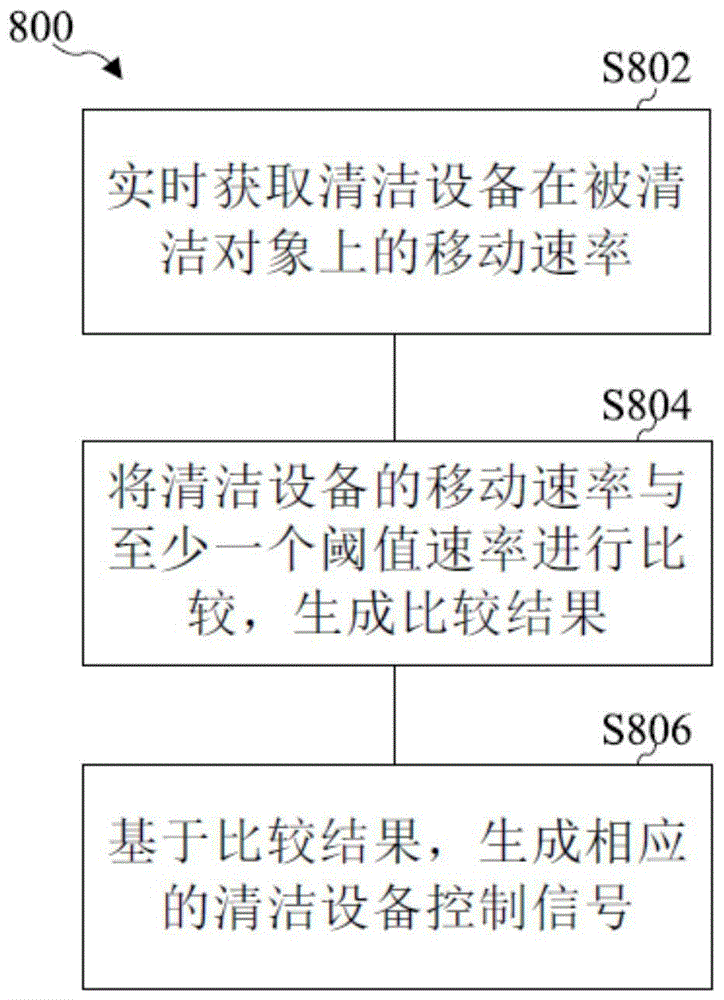
As shown in fig. 1, a cleaning apparatus automatic control method 800 according to one embodiment of the present disclosure includes:
s802, acquiring the moving speed of the cleaning equipment on the cleaned object in real time;
s804, comparing the moving speed of the cleaning equipment with at least one threshold speed to generate a comparison result; and the number of the first and second groups,
and S808, generating a corresponding cleaning device control signal based on the comparison result.
The cleaning apparatus may be a variety of floor scrubbing apparatus, vacuum cleaner apparatus, etc.
The object to be cleaned is, for example, a floor tile, a carpet, etc.
With the automatic cleaning apparatus control method 800 of the above embodiment, it is preferable that the cleaning apparatus control signal includes at least a first control signal and a second control signal, the first control signal controls the cleaning operation of the cleaning portion 102 of the cleaning apparatus 10, and the second control signal controls the cleaning liquid flow rate value output to the cleaning portion 102 by the cleaning liquid storage portion 211 of the cleaning apparatus 10.
The cleaning operation may be a rolling speed of the rolling brush type cleaning portion, a reciprocating frequency of the reciprocating type cleaning portion, a vibration frequency of the vibration type cleaning portion, or a rotation speed of the rotary type cleaning portion.
According to the automatic control method for the cleaning equipment, at least two control signals are simultaneously controlled, the linear relation between the control signals and the moving speed of the cleaning equipment in the prior art is removed, the cleaning efficiency of the cleaning equipment is further improved, the energy of the cleaning equipment is saved, and the loss of the cleaning equipment is reduced.
With the automatic control method 800 of the cleaning device of the above embodiment, it is preferable that the cleaning device control signal further includes a third control signal that controls the suction power output by the suction means 223 of the cleaning device.
With the automatic cleaning apparatus control method 800 of each of the above embodiments, preferably, when the moving speed of the cleaning apparatus is less than or equal to the first threshold speed, the first control signal controls the cleaning part 102 to output the first cleaning action, and the second control signal controls the cleaning liquid storage part 211 to output the first cleaning liquid flow value to the cleaning part 102.
For example, the first cleaning action may be a first rolling speed of the rolling brush type cleaning portion, or a first vibration frequency of the vibration type cleaning portion.
With the automatic cleaning apparatus control method 800 of each of the above embodiments, preferably, when the moving speed of the cleaning apparatus is greater than or equal to the first threshold speed and less than or equal to the second threshold speed, the first control signal controls the cleaning part 102 to output the second cleaning action, and the second control signal controls the cleaning liquid storage part 211 to output the second cleaning liquid flow value to the cleaning part 102.
With the automatic cleaning apparatus control method 800 of each of the above embodiments, it is preferable that the first control signal controls the cleaning section 102 to output the third cleaning action and the second control signal controls the cleaning liquid storage section 211 to output the third cleaning liquid flow value to the cleaning section 102 when the moving speed of the cleaning apparatus is greater than or equal to the second threshold speed and less than or equal to the third threshold speed.
With the automatic control method 800 of the cleaning apparatus of each of the above embodiments, it is preferable that the first control signal controls the cleaning section 102 to output the fourth cleaning action and the second control signal controls the cleaning liquid storage section 211 to output the fourth cleaning liquid flow value to the cleaning section 102 when the moving speed of the cleaning apparatus is greater than or equal to the third threshold speed.
With the automatic cleaning apparatus control method 800 of each of the above embodiments, preferably, when the moving speed of the cleaning apparatus is less than or equal to the first threshold speed, the first control signal controls the cleaning part 102 to output the first cleaning action, and the second control signal controls the cleaning liquid storage part 211 to output the first cleaning liquid flow value to the cleaning part 102, and the third control signal controls the suction device 223 of the cleaning apparatus 10 to output the first suction power.
With the automatic cleaning apparatus control method 800 of each of the above embodiments, preferably, when the moving speed of the cleaning apparatus is greater than or equal to the first threshold speed and less than or equal to the second threshold speed, the first control signal controls the cleaning part 102 to output the second cleaning action, and the second control signal controls the cleaning liquid storage part 211 to output the second cleaning liquid flow value to the cleaning part 102, and the third control signal controls the suction device 223 of the cleaning apparatus 10 to output the second suction power.
With the automatic cleaning apparatus control method 800 of each of the above embodiments, preferably, when the moving speed of the cleaning apparatus is greater than or equal to the second threshold speed and less than or equal to the third threshold speed, the first control signal controls the cleaning part 102 to output the third cleaning action, and the second control signal controls the cleaning liquid storage part 211 to output the third cleaning liquid flow value to the cleaning part 102, and the third control signal controls the suction device 223 of the cleaning apparatus 10 to output the third suction power.
With the automatic cleaning apparatus control method 800 of each of the above embodiments, preferably, when the moving speed of the cleaning apparatus is greater than or equal to the third threshold speed, the first control signal controls the cleaning part 102 to output the fourth cleaning action, and the second control signal controls the cleaning liquid storage part 211 to output the fourth cleaning liquid flow value to the cleaning part 102, and the third control signal controls the suction device 223 of the cleaning apparatus 10 to output the fourth suction power.
As can be seen from the above embodiments, it is preferable to divide the moving speed of the cleaning device into at least two speed intervals, and within each speed interval, to simultaneously control at least two kinds of control signals at a set value.
According to still another preferred embodiment of the present disclosure, as shown in fig. 2, the cleaning device automatic control method 900 includes:
s902, acquiring the moving speed and the moving direction of the cleaning equipment on the cleaned object in real time;
s904, comparing the moving speed of the cleaning equipment with at least one threshold speed to generate a comparison result; and the number of the first and second groups,
and S906, generating a corresponding cleaning device control signal based on the comparison result and the moving direction.
With the automatic cleaning apparatus control method 900 according to the above-described embodiment, it is preferable that the cleaning apparatus control signal includes at least a first control signal and a second control signal, the first control signal controls the cleaning operation of the cleaning portion 102 of the cleaning apparatus 10, and the second control signal controls the cleaning liquid flow rate value output to the cleaning portion 102 by the cleaning liquid storage portion 211 of the cleaning apparatus 10.
The cleaning operation may be a rolling speed of the rolling brush type cleaning portion, a reciprocating frequency of the reciprocating type cleaning portion, a vibration frequency of the vibration type cleaning portion, or the like.
With the cleaning apparatus automatic control method 900 of the above embodiment, it is preferable that the cleaning apparatus control signal further includes a third control signal that controls the suction power output by the suction device 223 of the cleaning apparatus.
For the cleaning device automatic control method 900 of each of the above embodiments, it is preferable to perform control based on control logic described below.
With the automatic cleaning apparatus control method 900 of each of the above embodiments, when the moving direction of the cleaning apparatus is the forward direction and the moving speed of the cleaning apparatus is less than or equal to the first threshold speed, the first control signal controls the cleaning part 102 to output the first cleaning action, and the second control signal controls the cleaning liquid storage part 211 to output the first cleaning liquid flow value to the cleaning part 102.
With the automatic cleaning device control method 900 according to each of the above embodiments, when the moving direction of the cleaning device is the forward direction and the moving speed of the cleaning device is greater than or equal to the first threshold speed and less than or equal to the second threshold speed, the first control signal controls the cleaning unit 102 to output the second cleaning operation, and the second control signal controls the cleaning liquid storage unit 211 to output the second cleaning liquid flow value to the cleaning unit 102.
With the automatic cleaning apparatus control method 900 of each of the above embodiments, when the moving direction of the cleaning apparatus is the forward direction and the moving speed of the cleaning apparatus is greater than or equal to the second threshold speed and less than or equal to the third threshold speed, the first control signal controls the cleaning section 102 to output the third cleaning action, and the second control signal controls the cleaning liquid storage section 211 to output the third cleaning liquid flow value to the cleaning section 102.
With the automatic cleaning apparatus control method 900 of each of the above embodiments, when the moving direction of the cleaning apparatus is the forward direction and the moving speed of the cleaning apparatus is greater than or equal to the third threshold speed, the first control signal controls the cleaning section 102 to output the fourth cleaning action, and the second control signal controls the cleaning liquid storage section 211 to output the fourth cleaning liquid flow value to the cleaning section 102.
With the automatic cleaning apparatus control method 900 of each of the above embodiments, when the moving direction of the cleaning apparatus is the reverse direction, the second control signal controls the cleaning liquid storage portion 211 to stop outputting the cleaning liquid to the cleaning portion 102.
When the operator performs reciprocating operation of the cleaning device (such as a cleaner and a scrubber), the scrubber normally passes through an already cleaned area when the scrubber moves backward, and when the cleaning device 10 moves backward, the supply of cleaning liquid to the cleaning unit 102 is stopped.
With the automatic cleaning device control method 900 of each of the above embodiments, when the moving direction of the cleaning device is the reverse direction, the first control signal controls the cleaning section 102 to stop outputting the cleaning action.
When the cleaning device is moved backward, the output of the cleaning action is stopped, for example, when the roller-type cleaning device moves forward, the roller-type cleaning portion rolls forward, and if the roller-type cleaning portion continues to roll forward when the cleaning device is moved backward, the load of the driving motor of the roller-type cleaning portion is increased (energy consumption and damage to the driving motor) due to the frictional force of the floor.
With the cleaning apparatus automatic control method 900 of each of the above embodiments, preferably, the third control signal controls the suction device 223 of the cleaning apparatus 10 to output the fifth suction power when the moving direction of the cleaning apparatus is the reverse direction.
The fifth suction power may be a preset lower suction power, and when an operator performs reciprocating operation on the cleaning device (such as a dust collector, a floor washing machine and the like), the floor washing machine often passes through a cleaned area when moving backwards, so that energy saving is realized by reducing the suction power.
The cleaning apparatus of the present disclosure is explained in detail below with reference to fig. 3 to 6.
According to one embodiment of the present disclosure, the cleaning apparatus 10 includes:
a cleaning unit 102, the cleaning unit 102 being configured to clean an object to be cleaned;
the speed sensing device acquires the moving speed of the cleaning equipment 10 on the cleaned object in real time; and the number of the first and second groups,
and the control device 204 is in communication connection with the speed sensing device, the control device 204 compares the moving speed of the cleaning equipment with at least one threshold speed to generate a comparison result, and the control device 204 generates a corresponding cleaning equipment control signal based on the comparison result.
The communication connection can be a wired communication connection or a wireless communication connection.
With respect to the cleaning device 10 of the above embodiment, preferably, as shown in fig. 6, the control device 204 includes a processor 2041 and a memory 2042, the memory 2042 is used for storing at least one threshold speed, the processor 2041 compares the moving speed of the cleaning device with the at least one threshold speed to generate a comparison result, and the processor 2041 generates a corresponding cleaning device control signal based on the comparison result.
With respect to the cleaning device 10 of each of the above embodiments, preferably, the control device 204 further has a communication interface 2043, external control instructions can be transmitted to the processor 2041 via the communication interface 2043, and the processor 2041 can modify at least one threshold rate stored in the memory 2042 based on the external control instructions.
More preferably, at least two control signals stored in the memory 2042 may also be modified by external control instructions.
For each of the embodiments of cleaning device 10 described above, control device 204 is preferably communicatively coupled to the speed sensing device via communication interface 2043.
According to a preferred alternative embodiment of the present disclosure, the speed sensing device obtains the moving speed and moving direction of the cleaning device 10 on the object to be cleaned in real time, the control device 204 compares the moving speed of the cleaning device 10 with at least one threshold speed to generate a comparison result, and the control device 204 generates a corresponding cleaning device control signal based on the comparison result and the moving direction.
As shown in fig. 5, the cleaning device 10 of each of the above embodiments further includes a cleaning liquid storage 211, the cleaning device control signal includes at least a first control signal and a second control signal, the first control signal controls the cleaning operation of the cleaning unit 102 of the cleaning device 10, and the second control signal controls the cleaning liquid flow rate value output from the cleaning liquid storage 211 of the cleaning device 10 to the cleaning unit 102.
With the cleaning apparatus 10 of the above embodiment, it is preferable that the suction device 223 is further included, and the cleaning apparatus control signal further includes a third control signal which controls the suction power output by the suction device 223 of the cleaning apparatus 10.
The suction device 223 may be a fan device or the like.
With the cleaning apparatus 10 of each of the above embodiments, it is preferable that the first driving device 105 is further included, and the first driving device 105 is controllable by the control device 204 to drive the cleaning portion 102.
With the cleaning device 10 of each of the above embodiments, the cleaning portion 102 may be a rolling brush, a reciprocating brush, a rotary brush, or the like.
Of course, the cleaning portion 102 may have various structures in the related art.
With the cleaning device 10 of each of the above embodiments, it is preferable that it further includes a first housing 101, the first housing 101 has a cavity, and the first driving device 105 is disposed inside the cavity of the first housing 101; the cleaning part 102 is partially disposed within the cavity of the first housing 101, and the cleaning part 102 can be partially exposed from the cavity of the first housing 101.
Fig. 3 and 4 only show a part of the first casing 101.
With the cleaning device 10 of each of the above embodiments, it is preferable that the cleaning device 10 further includes a rotation support 103, and the rotation support 103 supports the cleaning device 10, and the cleaning device 10 is moved on the object to be cleaned by the rotating action of the rotation support 103.
As shown in fig. 3 and 4, the rotation support 103 may be a rolling wheel, two of which are shown in fig. 3 and 4.
The shape, number, etc. of the rolling wheels can be adjusted by a person skilled in the art.
As shown in fig. 4, a speed sensing device (preferably composed of a magnetic part 1041 and a magnetic signal sensor 1042) is disposed adjacent to the rotation support part 103, and the moving speed and the moving direction of the cleaning device 10 on the cleaning object are acquired by detecting the rotating speed and the rotating direction of the rotation support part 103.
According to a preferred embodiment of the present disclosure, the speed sensing means of the cleaning device 10 includes a magnetic part 1041 provided on the rotation support part 103, and a magnetic signal sensor 1042 provided on the first housing 101.
The magnetic part 1041 may be a permanent magnet, the magnetic signal sensor 1042 may be a hall sensor, or may be a reed switch; alternatively, the speed sensing means may be constituted by a code wheel provided on the inner side surface of the rotation support portion 103 to rotate following the rotation support portion 103, and an opto-electronic switch provided at a suitable position in the first housing 101 to detect a change in the code wheel signal by the opto-electronic switch to measure the rotation speed and/or direction of the rotation support portion 103, thereby acquiring the moving speed of the cleaning apparatus.
With the cleaning device 10 of the above embodiment, it is preferable that the rotation support portion 103 is a rolling wheel, the number of the magnetic portions 1041 is plural, and the plural magnetic portions 1041 are uniformly provided on the inner side surface of the rotation support portion 103.
With the cleaning device 10 of each of the above embodiments, further including the transmission 106, the first driving device 105 transmits the driving motion to the cleaning portion 102 via the transmission 106.
The transmission 106 may be a timing belt or other type of transmission.
As shown in fig. 3 and 4, the cleaning apparatus 10 preferably further includes a first pump device 108, the first pump device 108 delivering the cleaning liquid to the cleaning portion 102.
Preferably, the cleaning device 10 further comprises a liquid distributor 107, the liquid distributor 107 being arranged between the first pump means 108 and the cleaning portion 102.
The first pump means 108 and the liquid distributor 107 are arranged within the first housing 101.
According to a preferred embodiment of the present disclosure, the liquid distributor 107 of the cleaning device 10 includes a plurality of liquid nozzles through which the cleaning liquid is output to the cleaning part 102.
According to an alternatively preferred embodiment of the present disclosure, the liquid distributor 107 of the cleaning device 10 has a cavity and a plurality of liquid output holes, the liquid distributor 107 being capable of outputting the cleaning liquid delivered by the first pump means 108 into the cavity of the liquid distributor 107 to the cleaning portion 102 via the plurality of liquid output holes.
As shown in fig. 5, according to a preferred embodiment of the present disclosure, the cleaning device 10 further comprises a second housing 210, the second housing 210 having a cavity, the control means 204 being disposed within the cavity of the first housing 101 or within the cavity of the second housing 210.
In fig. 5, the control device 204 is disposed within a cavity of the second housing 210.
Preferably, with the cleaning device 10 of the above embodiment, the first housing 101 has the connecting portion 109, and the first housing 101 and the second housing 210 are fixedly connected by the connecting portion 109.
The connection portion 109 may be integrally formed with the first housing 101, and the first housing 101 and the second housing 210 are preferably detachably connected.
As shown in fig. 5, the cleaning apparatus 10 further includes a cleaning liquid storage portion 211 for storing a cleaning liquid, and a first delivery pipe 201, via which the cleaning liquid in the cleaning liquid storage portion 211 can be delivered to the cleaning portion 102.
As can be seen from fig. 5, one end of the first delivery pipe 201 communicates with the first pump device 108, and the other end of the first delivery pipe 201 communicates with the cleaning liquid storage portion 211.
With the cleaning apparatus 10 of each of the above embodiments, it is preferable that a temperature detector 213 is further included, and the temperature detector 213 is configured to detect the temperature of the cleaning liquid.
The temperature detector 213 may be provided within the cleaning liquid storage portion 211 or on the first delivery pipe 201.
With the cleaning device 10 of each of the above embodiments, it is preferable that a dirt storage part 221 is further included, the dirt storage part 221 is disposed within the cavity of the second housing 210 or within a receiving part formed on the second housing 210, and the dirt storage part 221 is used to recover dirt sucked through the cleaning part 102.
With the cleaning device 10 of the above embodiment, the recovery passage 222 is formed inside the second housing 210, and the dirt suctioned by the cleaning portion 102 enters the dirt storage portion 221 via the recovery passage 222.
Preferably, the inside of the second housing 210 is provided with the above-described suction device 223, and the suction device 223 supplies negative pressure to the cleaning part 102 via the dirt storage part 221 and the recovery passage 222, so that the dirt on the object to be cleaned can be sucked by the cleaning part 102.
The suction device 223 may be an air extractor or a fan, etc.
According to a preferred embodiment of the present disclosure, the inside of the filth storage part 221 is provided with a filtering device 224.
According to a preferred embodiment of the present disclosure, the filth storage part 221 has a top end and a bottom end opposite to the top end, the bottom end of the filth storage part 221 is connected with the recovery channel 222, and the filtering means 224 is disposed inside the top end of the filth storage part 221.
With the cleaning apparatus 10 of each of the above embodiments, it is also possible to include the second delivery pipe 202, the second delivery pipe 202 communicates with the first delivery pipe 201, and the cleaning liquid outside the cleaning apparatus 10 can be delivered to the cleaning liquid storage portion 211 via the second delivery pipe 202 and the first delivery pipe 201.
With the cleaning apparatus 10 of each of the above embodiments, the first end of the second delivery pipe 202 communicates with the first delivery pipe 201, the second end of the second delivery pipe 202 is connected with the first joint portion 203, and the second delivery pipe 202 can communicate with a cleaning liquid supply device outside the cleaning apparatus via the first joint portion 203.
With the cleaning device 10 of each of the above embodiments, a charging communication connector 205 may be further included, and the control device 204 is connected to the charging communication connector 205.
The charging communication connector 205 may be provided at a suitable location of the cleaning device 10, for example on an outer wall of the second housing.
The control device 204 may be in the form of a control chip or a control circuit board.
With the cleaning apparatus 10 of each of the above embodiments, it is preferable that the first detection device 212 is further included, the first detection device 212 being for detecting the in-place state of the cleaning liquid storage portion 211 and for detecting the liquid amount of the cleaning liquid in the cleaning liquid storage portion 211.
With the cleaning device 10 of each of the above embodiments, a power supply unit 206 is further included, and the power supply unit 206 is used for supplying power to the power-requiring components of the cleaning device.
The power supply 206 may be a rechargeable battery or the like.
By detecting the moving speed and/or moving direction of the cleaning equipment (such as a cleaning head device of the cleaning equipment) on the cleaned object, the water supply speed, the rolling brush speed and the suction power of the cleaning equipment are adjusted to be distributed according to the speed interval, so that the cleaning effect is ensured, the water quantity, the rolling brush and the suction power are prevented from being suddenly increased or decreased, the electric quantity is prevented from being wasted, and the excessive loss of a machine is avoided.
In the description herein, reference to the description of the terms "one embodiment/mode," "some embodiments/modes," "example," "specific example" or "some examples" or the like means that a particular feature, structure, material, or characteristic described in connection with the embodiment/mode or example is included in at least one embodiment/mode or example of the present disclosure. In this specification, the schematic representations of the terms used above are not necessarily intended to be the same embodiment/mode or example. Furthermore, the particular features, structures, materials, or characteristics described may be combined in any suitable manner in any one or more embodiments/modes or examples. Furthermore, the various embodiments/aspects or examples and features of the various embodiments/aspects or examples described in this specification can be combined and combined by one skilled in the art without conflicting therewith.
Furthermore, the terms "first", "second" and "first" are used for descriptive purposes only and are not to be construed as indicating or implying relative importance or implicitly indicating the number of technical features indicated. Thus, a feature defined as "first" or "second" may explicitly or implicitly include at least one such feature. In the description of the present disclosure, "a plurality" means at least two, e.g., two, three, etc., unless explicitly specifically limited otherwise.
It will be understood by those skilled in the art that the foregoing embodiments are merely for clarity of illustration of the disclosure and are not intended to limit the scope of the disclosure. Other variations or modifications may occur to those skilled in the art, based on the foregoing disclosure, and are still within the scope of the present disclosure.
Claims (10)
Priority Applications (1)
| Application Number | Priority Date | Filing Date | Title |
|---|---|---|---|
| CN202110373233.6A CN113243819A (en) | 2021-04-07 | 2021-04-07 | Automatic control method of cleaning equipment and cleaning equipment |
Applications Claiming Priority (1)
| Application Number | Priority Date | Filing Date | Title |
|---|---|---|---|
| CN202110373233.6A CN113243819A (en) | 2021-04-07 | 2021-04-07 | Automatic control method of cleaning equipment and cleaning equipment |
Publications (1)
| Publication Number | Publication Date |
|---|---|
| CN113243819A true CN113243819A (en) | 2021-08-13 |
Family
ID=77221761
Family Applications (1)
| Application Number | Title | Priority Date | Filing Date |
|---|---|---|---|
| CN202110373233.6A Pending CN113243819A (en) | 2021-04-07 | 2021-04-07 | Automatic control method of cleaning equipment and cleaning equipment |
Country Status (1)
| Country | Link |
|---|---|
| CN (1) | CN113243819A (en) |
Cited By (3)
| Publication number | Priority date | Publication date | Assignee | Title |
|---|---|---|---|---|
| CN114041723A (en) * | 2021-11-18 | 2022-02-15 | 苏州精源创智能科技有限公司 | Dust collector motion sensor module and method for detecting motion state of dust collector |
| CN114711675A (en) * | 2022-02-28 | 2022-07-08 | 深圳市追光智造科技有限公司 | Method, device and system for automatically adjusting gear of cleaning equipment and storage medium |
| CN116098529A (en) * | 2022-06-01 | 2023-05-12 | 宁波方太厨具有限公司 | Cleaning machine and water yield control method for cleaning machine |
Citations (9)
| Publication number | Priority date | Publication date | Assignee | Title |
|---|---|---|---|---|
| CN1550198A (en) * | 2003-05-08 | 2004-12-01 | Cleaning machine with control system for cleaning surfaces | |
| US20100281646A1 (en) * | 2006-09-11 | 2010-11-11 | Panasonic Corporation | Electric cleaner |
| JP2011030668A (en) * | 2009-07-30 | 2011-02-17 | Toshiba Corp | Vacuum cleaner |
| TW201611765A (en) * | 2014-09-24 | 2016-04-01 | Vorwerk Co Interholding | Vacuum cleaner and method for reducing electric power of suction fan motor while vacuum cleaner generating suction airflow |
| CN111053500A (en) * | 2020-01-02 | 2020-04-24 | 小狗电器互联网科技(北京)股份有限公司 | Method and device for controlling sweeping equipment to sweep along wall and sweeping equipment |
| CN111936023A (en) * | 2017-12-18 | 2020-11-13 | 创科地板护理技术有限公司 | Surface cleaning apparatus with triggerless fluid dispensing mechanism |
| CN112137502A (en) * | 2019-06-27 | 2020-12-29 | 尚科宁家(中国)科技有限公司 | Floor sweeping robot and cleaning control method thereof |
| CN112205924A (en) * | 2019-07-12 | 2021-01-12 | Lg电子株式会社 | Cleaner capable of controlling motor power and control method thereof |
| CN112294189A (en) * | 2019-07-25 | 2021-02-02 | 德国福维克控股公司 | Household cleaning appliance with battery-operated device |
-
2021
- 2021-04-07 CN CN202110373233.6A patent/CN113243819A/en active Pending
Patent Citations (9)
| Publication number | Priority date | Publication date | Assignee | Title |
|---|---|---|---|---|
| CN1550198A (en) * | 2003-05-08 | 2004-12-01 | Cleaning machine with control system for cleaning surfaces | |
| US20100281646A1 (en) * | 2006-09-11 | 2010-11-11 | Panasonic Corporation | Electric cleaner |
| JP2011030668A (en) * | 2009-07-30 | 2011-02-17 | Toshiba Corp | Vacuum cleaner |
| TW201611765A (en) * | 2014-09-24 | 2016-04-01 | Vorwerk Co Interholding | Vacuum cleaner and method for reducing electric power of suction fan motor while vacuum cleaner generating suction airflow |
| CN111936023A (en) * | 2017-12-18 | 2020-11-13 | 创科地板护理技术有限公司 | Surface cleaning apparatus with triggerless fluid dispensing mechanism |
| CN112137502A (en) * | 2019-06-27 | 2020-12-29 | 尚科宁家(中国)科技有限公司 | Floor sweeping robot and cleaning control method thereof |
| CN112205924A (en) * | 2019-07-12 | 2021-01-12 | Lg电子株式会社 | Cleaner capable of controlling motor power and control method thereof |
| CN112294189A (en) * | 2019-07-25 | 2021-02-02 | 德国福维克控股公司 | Household cleaning appliance with battery-operated device |
| CN111053500A (en) * | 2020-01-02 | 2020-04-24 | 小狗电器互联网科技(北京)股份有限公司 | Method and device for controlling sweeping equipment to sweep along wall and sweeping equipment |
Cited By (4)
| Publication number | Priority date | Publication date | Assignee | Title |
|---|---|---|---|---|
| CN114041723A (en) * | 2021-11-18 | 2022-02-15 | 苏州精源创智能科技有限公司 | Dust collector motion sensor module and method for detecting motion state of dust collector |
| CN114711675A (en) * | 2022-02-28 | 2022-07-08 | 深圳市追光智造科技有限公司 | Method, device and system for automatically adjusting gear of cleaning equipment and storage medium |
| WO2023159788A1 (en) * | 2022-02-28 | 2023-08-31 | 深圳市追光智造科技有限公司 | Automatic adjusting method, apparatus and system for gear of handheld cleaning device, and storage medium |
| CN116098529A (en) * | 2022-06-01 | 2023-05-12 | 宁波方太厨具有限公司 | Cleaning machine and water yield control method for cleaning machine |
Similar Documents
| Publication | Publication Date | Title |
|---|---|---|
| CN113243833A (en) | Automatic control method of cleaning equipment and cleaning equipment | |
| CN113425205B (en) | Surface cleaning method and surface cleaning apparatus | |
| JP3230331U (en) | Surface cleaning device with a drying cycle | |
| US20240148215A1 (en) | Base station and cleaning robot system | |
| CN113786138A (en) | Surface cleaning system and self-cleaning method for surface cleaning equipment | |
| CN113693519B (en) | Base station and surface cleaning system | |
| CN113243819A (en) | Automatic control method of cleaning equipment and cleaning equipment | |
| JP2021074544A (en) | Surface cleaning apparatus | |
| CN203263284U (en) | Electric dust collector | |
| CN112450805A (en) | Edge cleaning brush for floor cleaner | |
| WO2023088410A1 (en) | Cleaning apparatus and cleaning method | |
| JP2022505410A (en) | Surface cleaning device with proximity-triggered user interface | |
| CN215838750U (en) | Base station, cleaning robot and cleaning robot system | |
| US20250275662A1 (en) | Base station and cleaning robot system | |
| KR20050063547A (en) | Robot cleaner and operating method thereof | |
| KR20040035512A (en) | Suction head of robot cleaner | |
| CN113243844A (en) | Cleaning system and control method | |
| CN115381347B (en) | Cleaning apparatus and control method of cleaning apparatus | |
| EP4397221A1 (en) | Method for controlling suction based on detected operation angles | |
| CN217592765U (en) | Surface cleaning system | |
| CN113827143A (en) | Method for treating an active surface cleaning device and wet surface cleaning system | |
| CN215959624U (en) | Base station and cleaning robot system | |
| KR20210023649A (en) | Robot Cleaner And The control method thereof | |
| CN113907660A (en) | Wet surface cleaning device with lying cleaning mode and surface cleaning system | |
| CN103479290A (en) | Handheld type dust collector with beater |
Legal Events
| Date | Code | Title | Description |
|---|---|---|---|
| PB01 | Publication | ||
| PB01 | Publication | ||
| SE01 | Entry into force of request for substantive examination | ||
| SE01 | Entry into force of request for substantive examination | ||
| RJ01 | Rejection of invention patent application after publication | ||
| RJ01 | Rejection of invention patent application after publication |
Application publication date: 20210813 |