Disclosure of Invention
The invention provides a multiport energy conversion device for charging an electric automobile and a control method thereof, aiming at the defects of the prior art, the multi-port energy conversion device for charging the electric automobile simultaneously utilizes solar energy and electric energy of a power grid, can input or output various voltage grades through multiple ports when in need, has the advantages of small volume, light weight, small no-load loss and the like, not only has the functions of converting voltage and transmitting energy, but also has the functions of limiting fault current, compensating reactive power, improving electric energy quality, providing standardized interfaces for various devices and the like. The technical scheme adopted by the invention is as follows:
on one hand, the multi-port energy conversion device for charging the electric automobile comprises a three-phase voltage type PWM rectification unit, a double-active-bridge DC/DC conversion unit, an electric automobile mutual charging interface, a photovoltaic input unit, a Boost conversion unit, a storage battery unit, a single-phase full-bridge inversion unit, a Buck Buck conversion unit, a high-voltage direct current port 1 and a high-voltage direct current port 2;
the input end of the three-phase voltage type PWM rectifying unit is connected with a power grid, the output end of the three-phase voltage type PWM rectifying unit is connected with a high-voltage direct current port 1, the high-voltage direct current port 1 is simultaneously connected with the electric automobile mutual charging interface and the input end of the double-active bridge DC/DC conversion unit, and the high-voltage direct current port 2 is connected with the output end of the double-active bridge DC/DC conversion unit; the output end of the photovoltaic input unit is connected with the input end of the Boost conversion unit, and the output end of the Boost unit is connected with the high-voltage direct-current port 2; the input end of the storage battery unit, the input end of the single-phase full-bridge inversion unit and the input end of the Buck voltage reduction conversion unit are connected with the high-voltage direct current port 2, the output end of the single-phase full-bridge inversion unit is connected with a single-phase alternating current load or energy storage equipment, and the output end of the Buck voltage reduction unit is connected with a low-voltage direct current load or energy storage equipment;
the electric automobile mutual charging interface, the double-active-bridge DC/DC conversion unit and the single-phase full-bridge inversion unit respectively comprise three energy flow working modes, energy is transmitted in a forward direction from the input end to the output end, energy is transmitted in a reverse direction from the output end to the input end, and no energy flows, so that the energy is not transmitted;
on the other hand, the control method of the multi-port energy conversion device for charging the electric automobile is realized based on the multi-port energy conversion device for charging the electric automobile, and comprises the following steps:
step 1: the double-active DC/DC converter adopts model prediction control, simultaneously takes the influence of external factors into consideration, introduces an error correction parameter epsilon to compensate the deviation, and comprises the following specific steps:
step 1.1: the simplified reduced-order model for modeling the output voltage of the double-active DC/DC converter to obtain DAB is as follows:
wherein R isLIs a load resistance value, C1For output capacitance, L is the leakage inductance value of the transformer, n is the transformation ratio of the transformer, D is the duty ratio, fsIs the switching frequency;
step 1.2: discretizing the output voltage differential term by adopting an Euler forward method to obtain:
wherein, TsIs a switching cycle;
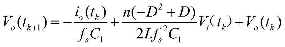
step 1.3: substituting the formula in the step 1.1 into the formula in the step 1.2 to obtain:
wherein, Vi(tk)、Vo(tk) And io(tk) Are each tkInputting voltage, output voltage and output current sampling values at all times;
step 1.4: establishing an evaluation function J (k) ═ V
o(t
k+1)-V
oref)
2Derived to obtain the duty ratio
Wherein
V
orefIs the output voltage reference value;
step 1.5: the expression of the predicted optimal phase shift ratio after introducing the error correction parameter epsilon is Din=εD;
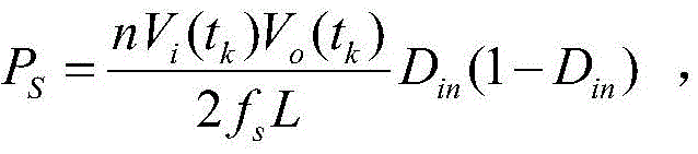
Step 1.6: obtaining the output power of the DAB converter under model predictive control
Actual duty cycle of
Step 2: the electric vehicle mutual charging technology is realized by adopting multi-objective optimization control based on model prediction, and the method specifically comprises the following steps:
step 2.1: setting a new energy output power regulation function as follows:
wherein: omega
pvThe temperature conversion power coefficient of the photovoltaic is adopted, T is the temperature at the current moment, T
refIs a nominal reference temperature, s
pvIs at presentThe intensity of the light at the moment of time,
and outputting the rated value of the power for the new energy.
Step 2.2: setting a new energy input electric vehicle micro-grid power prediction function as follows:
wherein: p
pv-inThe power of the electric automobile is input for the photovoltaic energy source,
predicting an error value, η, for photovoltaic power
pvAnd λ
pvRespectively obtaining the mean value and the variance of the photovoltaic power prediction error through data statistics;
step 2.3: setting a power regulation function of the electric automobile micro-grid system as follows:
where τ is the state of charge of the battery, P1For power input at the grid port, P2For another electric vehicle, P3For outputting power, P, to a single-phase AC port4For output of power, P, to a low-voltage DC interfaceBNRated input power for the storage battery;
step 2.4: setting a multi-objective optimization control function of the electric vehicle micro-grid system as
Wherein P iss=P1+P2+P3+P4+Ppv-in,
The battery charging conversion efficiency is
Conversion efficiency of single-phase AC equipment
Low voltage dc load conversion efficiency
Wherein the multiple target limiting condition is
Alpha, beta, gamma are weight factors, etaB、η3、η4The battery charging conversion efficiency, the single-phase alternating current equipment conversion efficiency and the low-voltage direct current load conversion efficiency are respectively optimized when constraint conditions are met and the multi-objective optimization function F (t) reaches the minimum value.
Step 2.5: to etaB、η3、η4Performing a separate solution to obtain (P)1,P2,P3,P4),(P1,P2,P3,P4)(2),(P1,P2,P3,P4)(3)The single index under three groups of constraint conditions is optimal: (P)1,P2,P3,P4) The battery charging conversion efficiency, the single-phase AC equipment conversion efficiency and the low-voltage DC load conversion efficiency are respectively f1、f2、f3;(P1,P2,P3,P4)(2)Of a batteryThe charging conversion efficiency, the single-phase alternating current equipment conversion efficiency and the low-voltage direct current load conversion efficiency are respectively f1 (2)、f2 (2)、f3 (2);(P1,P2,P3,P4)(3)The battery charging conversion efficiency, the single-phase AC equipment conversion efficiency and the low-voltage DC load conversion efficiency are respectively f1 (3)、f2 (3)、f3 (3);
Step 2.6: obtaining the maximum value M in the optimal solution corresponding to each index according to the step 2.5jAnd the minimum value m in the optimal solution corresponding to each indexjAnd carrying out normalization processing calculation.
Determining weighting coefficients
Wherein i, j is 1,2,3
Step 2.7: constructing a multi-objective planimetric problem
Wherein i, j is 1,2, 3; mu is the sum of the battery charging conversion efficiency, the single-phase alternating current equipment conversion efficiency and the low-voltage direct current load conversion efficiency; obtaining a set of ideal solutions (P)
1,P
2,P
3,P
4)
*Bringing the ideal solution to step 2.4
1、f
2And f
3And (4) comparing functions of the three indexes, ending the calculation if the deviation of each index is less than or equal to 5%, and otherwise, skipping to the step 2.8.
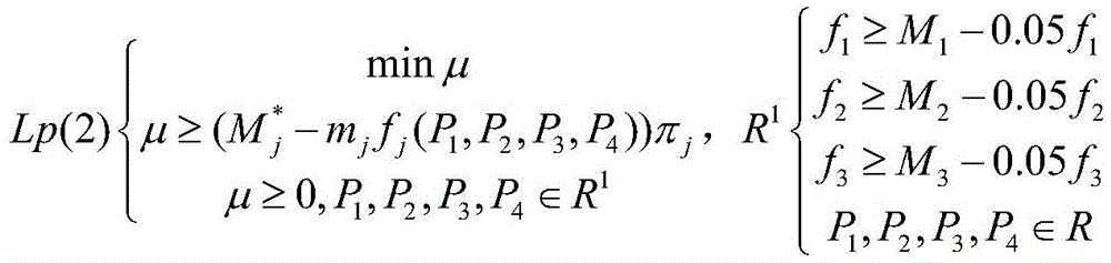
Step 2.8: and if the index which does not meet the requirement is less than the single index and is optimal, constructing a multi-target programming problem Lp (2).
Wherein j is 1,2 and 3 is presetUntil the deviation is less than 5%, if not, repeating step 2.8 until a set of actual ideal solutions (P) is output1,P2,P3,P4)*And obtaining the optimal power, thereby realizing the model prediction multi-objective optimization power control effect of the electric vehicle charging.
Adopt the produced beneficial effect of above-mentioned technical scheme to lie in:
the invention provides a multi-port energy conversion device for charging an electric automobile and a control method thereof, wherein each port has the characteristics of plug and play, has various voltage levels, can meet the requirement of charging diversity of the electric automobile, and can support the charging requirements of various devices and loads in the automobile.
The device realizes voltage conversion and energy transfer in the charging process through a power electronic conversion technology, and compared with the traditional electric automobile charger, the device not only has the functions of converting voltage and transferring energy, but also has multiple functions of limiting fault current, compensating reactive power, improving electric energy quality, providing standardized interfaces for various devices and the like; this device adopts the syllogic method of charging, charges according to the actual electric quantity of battery, has guaranteed the high efficiency and utilization ratio of energy to for the specific protection switch of battery installation, prevent the harm of overcharging to the battery.
The double-active-bridge DC-DC conversion unit provided by the device can continuously work at a high-frequency part above 20kHZ, and can support the transmission of higher power; meanwhile, compared with the traditional PI control method, the model prediction error correction control method can accurately predict the dynamic behavior of the output voltage at the next moment, has higher dynamic response speed, can reduce the influence of the input or removal of equipment at all levels on the whole system to a greater extent, can realize the bidirectional flow of the energy of the whole device, and provides a technical basis for vehicle charging.
The device provided by the invention provides an electric vehicle mutual charging technology, adopts multi-objective optimization control based on model prediction, can accurately control input current and power while meeting the charging voltage of the battery, can predict the maximum input power of new energy by establishing a multi-objective optimization control function and corresponding limiting conditions, and can reasonably distribute the power of each part.
Detailed Description
The following detailed description of embodiments of the invention refers to the accompanying drawings.
On one hand, the multi-port energy conversion device for charging the electric automobile comprises a three-phase voltage type PWM rectification unit, a double-active-bridge DC/DC conversion unit, an electric automobile mutual charging interface, a photovoltaic input unit, a Boost conversion unit, a storage battery unit, a single-phase full-bridge inversion unit, a Buck Buck conversion unit, a high-voltage direct-current port 1 and a high-voltage direct-current port 2, wherein the three-phase voltage type PWM rectification unit, the double-active-bridge DC/DC conversion unit, the electric automobile mutual charging interface, the photovoltaic input unit, the Boost conversion unit, the storage battery unit, the single-phase full-bridge inversion unit, the Buck Buck conversion unit, the high-voltage direct-current port 1 and the high-voltage direct-current port 2 are shown in figures 1 and 2;
the input end of the three-phase voltage type PWM rectifying unit is connected with a power grid, the output end of the three-phase voltage type PWM rectifying unit is connected with a high-voltage direct current port 1, the high-voltage direct current port 1 is simultaneously connected with the electric automobile mutual charging interface and the input end of the double-active bridge DC/DC conversion unit, and the high-voltage direct current port 2 is connected with the output end of the double-active bridge DC/DC conversion unit; the output end of the photovoltaic input unit is connected with the input end of the Boost conversion unit, and the output end of the Boost unit is connected with the high-voltage direct-current port 2; the input end of the storage battery unit, the input end of the single-phase full-bridge inversion unit and the input end of the Buck voltage reduction conversion unit are connected with the high-voltage direct current port 2, the output end of the single-phase full-bridge inversion unit is connected with a single-phase alternating current load or energy storage equipment, and the output end of the Buck voltage reduction unit is connected with a low-voltage direct current load or energy storage equipment;
the electric automobile mutual charging interface, the double-active-bridge DC/DC conversion unit and the single-phase full-bridge inversion unit respectively comprise three energy flow working modes, energy is transmitted in a forward direction from the input end to the output end, energy is transmitted in a reverse direction from the output end to the input end, and no energy flows, so that the energy is not transmitted; due to the different energy flowing directions in the units, a plurality of working modes of the multi-port energy conversion device are formed.
In this embodiment, the three-phase voltage type PWM rectification unit is shown in fig. 3, and is configured to implement mutual power conversion between a power grid and a high-voltage dc power, implement that the three-phase voltage type PWM rectification unit works in a rectification working mode according to a space vector control method, convert an ac power input to a power distribution network into a high-voltage dc power through the three-phase voltage type PWM rectification unit, and maintain a sinusoidal waveform of an input current of the power distribution network and synchronization with an input voltage of the power distribution network, so as to obtain a unit input power factor, implement reactive power compensation, and maintain a voltage at a dc side high-voltage dc port 2 connected to the three-phase voltage type PWM rectification unit to be constant. (ii) a The voltage level of the input end of the three-phase voltage type PWM rectifying unit is adjustable and is about 380V-3.3 KV, and in the embodiment, the voltage of the input end is 380V.
The voltage level of the high-voltage direct current port 1 is adjustable and is about 400V-800V, and in the embodiment, the voltage level of the high-voltage direct current port 1 is 600V. The voltage level of the high-voltage direct current port 2 is adjustable, and is about 50V-400V, and in the embodiment, the voltage level of the high-voltage direct current port 2 is 200V.
The double-active-bridge DC/DC conversion unit is shown in FIG. 4, and is used for realizing mutual power conversion between voltage levels of the high-voltage direct current port 1 and the high-voltage direct current port 2 and working in a voltage boosting working mode or a voltage reducing working mode; compared with the traditional PI control method, the method can accurately predict the dynamic behavior of the output voltage at the next moment, has higher dynamic response speed, can reduce the influence of the input or removal of equipment at each level on the whole system to a greater extent, can realize the bidirectional flow of the energy of the whole device, and provides technical support for the charging of vehicles. Meanwhile, the influence of external factors is considered, and the deviation exists between the predicted value and the true value, so that error correction parameters are introduced to compensate the deviation. The double-active-bridge DC/DC conversion unit is used as a middle key link of the device, has the function of starting and stopping, and is a main hardware structure of the vehicle-to-vehicle charging technology.
The single-phase full-bridge bidirectional inverter unit is shown in fig. 6, and is used for realizing the interconversion between low-voltage direct current and 220V alternating current voltage and realizing the operation of the single-phase full-bridge bidirectional inverter unit in a rectification working mode or an inversion working mode; the mutual conversion between the high-voltage direct current and the 220V alternating current voltage is realized, the work of the high-voltage direct current and the 220V alternating current voltage is realized in a rectification working mode or an inversion working mode according to different control modes, and the mutual energy flowing between the single-phase alternating current load and the energy storage equipment and the 200V high-voltage direct current port 2 is realized.
The Boost conversion unit is shown in fig. 5, and is used for realizing power conversion after new energy is accessed, boosting the power to meet the voltage requirement of the high-voltage direct-current port 2, and accessing the power to the high-voltage direct-current port 2 to realize that the power works in a Boost working mode; the photovoltaic energy is converted into direct current to provide electric energy input for the device, the utilization rate of new energy is improved, and auxiliary energy is provided for charging the storage battery.
The Buck conversion unit is shown in fig. 7, and is used for converting the output voltage of the high-voltage dc port 2 into low-voltage dc to provide appropriate dc voltage for low-voltage equipment.
Each interface end of the three-phase voltage type PWM rectifying unit, the double-active-bridge DC/DC converting unit, the Boost converting unit, the single-phase full-bridge inverting unit and the Buck voltage-reducing converting unit can provide proper interface voltage characteristics, and each unit is simple in structure, outstanding in cost performance and easy to realize; the double-active-bridge DC/DC conversion unit comprises a close-coupled high-frequency transformer, and has high transmission power density, small volume, high efficiency and simple control; the multiport energy conversion device can be connected with three-phase alternating current from a power grid, new energy can be introduced into a high-voltage direct-current port 2, another electric automobile can be connected into a mutual charging interface of the electric automobile, the charging technology of mutual charging of the automobiles can be realized, the requirements of various charging voltage levels of the electric automobile are met, and the plug-and-play characteristic of the multiport energy conversion device is realized through the design of the whole hardware structure.
On the other hand, the control method of the multi-port energy conversion device for charging the electric automobile is realized based on the multi-port energy conversion device for charging the electric automobile, and comprises the following steps:
step 1: the double-active DC/DC converter adopts model prediction control, simultaneously takes the influence of external factors into consideration, introduces an error correction parameter epsilon to compensate the deviation, and comprises the following specific steps:
step 1.1: the simplified reduced-order model for modeling the output voltage of the double-active DC/DC converter to obtain DAB is as follows:
wherein R isLIs a load resistance value, C1For output capacitance, L is the leakage inductance value of the transformer, n is the transformation ratio of the transformer, D is the duty ratio, fsIs the switching frequency;
step 1.2: discretizing the output voltage differential term by adopting an Euler forward method to obtain:
wherein, TsIs a switching cycle;
step 1.3: substituting the formula in the step 1.1 into the formula in the step 1.2 to obtain:
wherein, Vi(tk)、Vo(tk) And io(tk) Are each tkInputting voltage, output voltage and output current sampling values at all times;
step 1.4: establishing an evaluation function J (k) ═ V
o(t
k+1)-V
oref)
2Derived to obtain the duty ratio
Wherein
V
orefIs the output voltage reference value;
step 1.5: the expression of the predicted optimal phase shift ratio after introducing the error correction parameter epsilon is Din=εD;
Step 1.6: obtaining the output power of the DAB converter under model predictive control
Actual duty cycle of
Step 2: the electric vehicle mutual charging technology is realized by adopting multi-objective optimization control based on model prediction, and the method specifically comprises the following steps:
step 2.1: setting a new energy output power regulation function as follows:
wherein: omega
pvThe temperature conversion power coefficient of the photovoltaic is adopted, T is the temperature at the current moment, T
refIs a nominal reference temperature, s
pvFor the intensity of the light at the present moment,
and outputting the rated value of the power for the new energy.
Step 2.2: setting a new energy input electric vehicle micro-grid power prediction function as follows:
wherein: p
pv-inThe power of the electric automobile is input for the photovoltaic energy source,
predicting an error value, η, for photovoltaic power
pvAnd λ
pvRespectively obtaining the mean value and the variance of the photovoltaic power prediction error through data statistics;
step 2.3: setting a power regulation function of the electric automobile micro-grid system as follows:
where τ is the state of charge of the battery, P1For power input at the grid port, P2For another electric vehicle, P3For outputting power, P, to a single-phase AC port4For output of power, P, to a low-voltage DC interfaceBNRated input power for the storage battery;
step 2.4: setting a multi-objective optimization control function of the electric vehicle micro-grid system as
Wherein P iss=P1+P2+P3+P4+Ppv-in,
The battery charging conversion efficiency is
Conversion efficiency of single-phase AC equipment
Low voltage dc load conversion efficiency
Wherein the multiple target limiting condition is
α ═ 0.36, β ═ 0.48, γ ═ 0.43, and ηB、η3、η4The battery charging conversion efficiency, the single-phase alternating current equipment conversion efficiency and the low-voltage direct current load conversion efficiency are respectively optimized when constraint conditions are met and the multi-objective optimization function F (t) reaches the minimum value.
Step 2.5: to etaB、η3、η4Performing a separate solution to obtain (P)1,P2,P3,P4),(P1,P2,P3,P4)(2),(P1,P2,P3,P4)(3)The single index under three groups of constraint conditions is optimal: (P)1,P2,P3,P4) The battery charging conversion efficiency, the single-phase AC equipment conversion efficiency and the low-voltage DC load conversion efficiency are respectively f1、f2、f3;(P1,P2,P3,P4)(2)The battery charging conversion efficiency, the single-phase AC equipment conversion efficiency and the low-voltage DC load conversion efficiency are respectively f1 (2)、f2 (2)、f3 (2);(P1,P2,P3,P4)(3)The battery charging conversion efficiency, the single-phase AC equipment conversion efficiency and the low-voltage DC load conversion efficiency are respectively f1 (3)、f2 (3)、f3 (3);
Step 2.6: obtaining the maximum value M in the optimal solution corresponding to each index according to the step 2.5jAnd the minimum value m in the optimal solution corresponding to each indexjAnd carrying out normalization processing calculation.
Determining weighting coefficients
Wherein i, j is 1,2,3
Step 2.7: constructing a multi-objective planimetric problem
Wherein i, j is 1,2, 3; mu is the sum of the battery charging conversion efficiency, the single-phase alternating current equipment conversion efficiency and the low-voltage direct current load conversion efficiency; obtaining a set of ideal solutions (P)
1,P
2,P
3,P
4)
*Bringing the ideal solution to step 2.4
1、f
2And f
3And (4) comparing functions of the three indexes, ending the calculation if the deviation of each index is less than or equal to 5%, and otherwise, skipping to the step 2.8.
Step 2.8: and if the index which does not meet the requirement is less than the single index and is optimal, constructing a multi-target programming problem Lp (2).
Wherein j is 1,2,3, comparing preset deviation until the deviation is less than 5%, otherwise repeating step 2.8 until outputA set of actual ideal solutions (P) is obtained1,P2,P3,P4)*The obtained power is the optimal power, so that the model prediction multi-objective optimization power control effect of the electric vehicle charging is realized, the maximum input power of new energy can be predicted while the battery charging voltage is met, and meanwhile, the power of each part can be optimally distributed.
In this embodiment, the energy flow mode of each unit when the vehicle charging is realized is as follows:
as shown in fig. 8, the embodiment is mainly used for charging a storage battery, and then considering the charging condition of other ports, the state that energy of each unit flows from an input end to an output end and is transmitted in a forward direction is represented by "1", the state that energy flows from each output end to the input end and is transmitted in a reverse direction is represented by "-1", and the state that energy does not flow through each unit and is stopped is defined by "0"; the inherent hardware characteristics of the energy conversion unit used make it have a plurality of possible operation modes, and improve the charging and discharging reliability and the energy flow diversity, taking the car charging mode as an example, the operation states of each unit according to the above definition can be listed as 12 operable operation modes according to the energy flow direction, as shown in table 1, specifically as follows:
working mode 1: power flows to high-voltage direct current port 2 by the battery pack input end, flows to two active bridge DC/DC conversion unit output, flows to two active bridge DC/DC conversion unit input, flows into high-voltage direct current port 1, and the interface is mutually filled to the electric automobile that flows to, and electric automobile fills the interface each other this moment and can insert another electric automobile, can realize charging each other between two cars.
The working mode 2 is as follows: power flows to high voltage direct current port 2 by the battery pack input, flows to Buck conversion unit input, flows out Buck conversion unit output, flows to two active bridge DC conversion unit outputs simultaneously, flows to two active bridge DC conversion unit inputs, flows in high voltage direct current port 1, flows to electric automobile and fills the interface each other, and electric automobile fills the interface each other this moment and can insert another electric automobile, can realize charging each other between two cars.
Working mode 3: power flows to high voltage direct current port 2 by the battery pack input, flows to single-phase full-bridge contravariant unit input, flows out single-phase full-bridge contravariant unit output, flows to two active bridge DC/DC transform unit output simultaneously, flows to two active bridge DC/DC transform unit input, flows in high voltage direct current port 1, flows to the electric automobile and fills the interface each other, and electric automobile fills the interface each other this moment and can insert another electric automobile, can realize charging each other between two cars.
The working mode 4 is as follows: power flows to high voltage direct current port 2 by the battery pack input, flow to single-phase full-bridge contravariant unit input and Buck transform unit input, flow out single-phase full-bridge contravariant unit output and Buck transform unit output, flow to two active bridge DC/DC transform unit outputs simultaneously, flow to two active bridge DC/DC transform unit inputs, flow in high voltage direct current port 1, the interface is mutually filled to the flow direction electric automobile, electric automobile fills the interface each other this moment and can inserts another electric automobile, can realize charging each other between two cars.
The working mode 5 is as follows: power flows to high voltage direct current port 2 by battery pack input and single-phase full-bridge contravariant unit output, flows to two active bridge DC/DC conversion unit outputs, flows to two active bridge DC/DC conversion unit inputs, flows into high voltage direct current port 1, flows to electric automobile and fills the interface each other, and electric automobile fills the interface each other this moment and can insert another electric automobile, can realize charging each other between two cars.
The working mode 6 is as follows: power flows to high voltage direct current port 2 by battery pack input and single-phase full-bridge contravariant unit output, flows to Buck step-down transform unit input, flows out Buck step-down transform unit output, the two active bridge DC transform unit output of flow direction simultaneously, the two active bridge DC transform unit input of flow direction, flow in high voltage direct current port 1, the interface is mutually filled to the electric automobile of flow direction, electric automobile fills the interface each other this moment and can insert another electric automobile, can realize charging each other between two cars.
The working mode 7 is as follows: power flows to high voltage direct current port 2 by the battery pack input, and photovoltaic input power flows to Boost transform unit input simultaneously, and the output flows out to high voltage direct current port 2, flows to two active bridge DC/DC transform unit outputs, flows to two active bridge DC/DC transform unit inputs, flows in high voltage direct current port 1, and the interface is filled each other to the electric automobile that flows to, and electric automobile fills the interface each other this moment and can insert another electric automobile, can realize charging each other between two cars.
The working mode 8 is as follows: power is by battery pack input flow direction high voltage direct current port 2, photovoltaic input power flow direction Boost transform unit input simultaneously, the output flows out high voltage direct current port 2, flow direction Buck transform unit input, flow out Buck transform unit output, flow direction two active bridge DC/DC transform unit outputs simultaneously, flow direction two active bridge DC/DC transform unit inputs, flow in high voltage direct current port 1, the interface is filled each other to the flow direction electric automobile, electric automobile fills the interface each other this moment and can inserts another electric automobile, can realize charging each other between two cars.
The working mode 9: power is by battery pack input flow direction high voltage direct current port 2, photovoltaic input power flow direction Boost transform unit input simultaneously, the output flows out high voltage direct current port 2, flow direction single-phase full-bridge contravariant unit input, flow out single-phase full-bridge contravariant unit output, flow direction two active bridge DC/DC transform unit output simultaneously, flow direction two active bridge DC/DC transform unit input, flow in high voltage direct current port 1, flow direction electric automobile fills the interface each other, electric automobile fills the interface each other this moment and can inserts another electric automobile, can realize charging each other between two cars.
Operation mode 10: power flows to high voltage direct current port 2 by the battery pack input, photovoltaic input power flows to Boost transform unit input simultaneously, the output flows out high voltage direct current port 2, flow to single-phase full-bridge contravariant unit input and Buck transform unit input, flow out single-phase full-bridge contravariant unit output and Buck transform unit output, flow to two active bridge DC/DC transform unit outputs simultaneously, flow to two active bridge DC/DC transform unit inputs, flow in high voltage direct current port 1, the interface is mutually filled to the electric automobile to the flow direction, electric automobile fills the interface each other this moment and can inserts another electric automobile, can realize charging each other between two cars.
Operation mode 11: power flows to high voltage direct current port 2 by battery pack input and single-phase full-bridge contravariant unit output, and photovoltaic input power flows to Boost transform unit input simultaneously, and the output flows out to high voltage direct current port 2, flows to two active bridge DC/DC transform unit outputs, flows to two active bridge DC/DC transform unit inputs, flows in high voltage direct current port 1, the interface is filled each other to the electric automobile of flow direction, the electric automobile interface of filling each other this moment can insert another electric automobile, can realize charging each other between two cars.
Operation mode 12: power flows to high voltage direct current port 2 by battery pack input and single-phase full-bridge contravariant unit output, photovoltaic input power flows to Boost transform unit input simultaneously, the output flows out high voltage direct current port 2, flow direction Buck transform unit input, flow out Buck transform unit output, flow direction two active bridge DC/DC transform unit outputs simultaneously, flow direction two active bridge DC/DC transform unit inputs, flow in high voltage direct current port 1, flow direction electric automobile fills the interface each other, electric automobile fills the interface each other this moment and can inserts another electric automobile, can realize charging each other between two cars.
TABLE 1 working modes of a multi-port energy conversion device applied to electric vehicle charging
And (4) surface note:
definition of one, unit
Unit A: three-phase voltage type PWM rectifying unit
Unit B: electric automobile mutual charging interface
Unit C: dual active bridge DC/DC conversion unit
A unit D: boost conversion unit
And E unit: battery cell
And F unit: single-phase full-bridge inversion unit
A unit G: buck voltage reduction conversion unit
Second, defining the working mode state
1. Defining the energy of each unit to flow from the input end of each unit to the output end of the unit: 1 state;
2. defining the energy of each unit to flow from the output end of each unit to the input end of the unit: -1 state;
3. define no energy flow for each unit: a 0 state;
finally, it should be noted that: the above embodiments are only used to illustrate the technical solution of the present invention, and not to limit the same; while the invention has been described in detail and with reference to the foregoing embodiments, it will be understood by those skilled in the art that: the technical solutions described in the foregoing embodiments may still be modified, or some or all of the technical features may be equivalently replaced; such modifications and substitutions do not depart from the spirit of the corresponding technical solutions and scope of the present invention as defined in the appended claims.