CN113166633A - Self-orienting shaped abrasive particles - Google Patents
Self-orienting shaped abrasive particles Download PDFInfo
- Publication number
- CN113166633A CN113166633A CN201980080085.XA CN201980080085A CN113166633A CN 113166633 A CN113166633 A CN 113166633A CN 201980080085 A CN201980080085 A CN 201980080085A CN 113166633 A CN113166633 A CN 113166633A
- Authority
- CN
- China
- Prior art keywords
- shaped abrasive
- degrees
- abrasive particles
- planar
- continuous surface
- Prior art date
- Legal status (The legal status is an assumption and is not a legal conclusion. Google has not performed a legal analysis and makes no representation as to the accuracy of the status listed.)
- Pending
Links
Images








Classifications
-
- C—CHEMISTRY; METALLURGY
- C09—DYES; PAINTS; POLISHES; NATURAL RESINS; ADHESIVES; COMPOSITIONS NOT OTHERWISE PROVIDED FOR; APPLICATIONS OF MATERIALS NOT OTHERWISE PROVIDED FOR
- C09K—MATERIALS FOR MISCELLANEOUS APPLICATIONS, NOT PROVIDED FOR ELSEWHERE
- C09K3/00—Materials not provided for elsewhere
- C09K3/14—Anti-slip materials; Abrasives
- C09K3/1409—Abrasive particles per se
Landscapes
- Chemical & Material Sciences (AREA)
- Engineering & Computer Science (AREA)
- Materials Engineering (AREA)
- Organic Chemistry (AREA)
- Polishing Bodies And Polishing Tools (AREA)
Abstract
Various embodiments disclosed herein relate to a shaped abrasive particle. The shaped abrasive particles include a first non-planar continuous surface and a second non-planar continuous surface. The shaped abrasive particles further include at least one sidewall or edge joining the first non-planar continuous surface and the second non-planar continuous surface. The shaped abrasive particles also include one or more vertices. The shaped abrasive particles are configured to have a stable resting position on a substantially planar base with at least one vertex oriented in a substantially upward direction relative to the planar base.
Description
Background
Abrasive particles and abrasive articles including abrasive particles can be used to abrade, condition, or grind a variety of materials and surfaces during the manufacture of the products. Accordingly, there is a continuing need for improved cost, performance, or life of abrasive particles or abrasive articles.
Disclosure of Invention
The present disclosure provides a shaped abrasive particle. The shaped abrasive particles include a first non-planar continuous surface and a second non-planar continuous surface. The shaped abrasive particles further include at least one sidewall or edge joining the first non-planar continuous surface and the second non-planar continuous surface. The shaped abrasive particles also include one or more vertices. The shaped abrasive particles are configured to have a stable resting position on a substantially planar base with at least one vertex oriented in a substantially upward direction relative to the planar base.
The present disclosure also provides a shaped abrasive particle comprising a curved portion. The shaped abrasive particle further includes a linear portion extending from the curved portion, the linear portion defining at least one apex. The center of gravity of the abrasive particles is located in the curved portion.
The present disclosure also provides a twisted shaped abrasive particle. The twisted shaped abrasive particle includes a first portion including a first edge defining a first vertex and a second vertex. The twisted shaped abrasive particle further includes a second section connected to the first section and including a second edge defining a third apex and a fourth apex. The first portion is twisted relative to the second portion such that only three of the first vertex, the second vertex, the third vertex, and the fourth vertex may lie in a single plane.
The present disclosure also provides a curved shaped abrasive particle. The curved shaped abrasive particle includes a first portion including a first edge defining a first apex. The curved shaped abrasive particle also includes a second section connected to the first section and including a second edge defining a second apex. The first portion is curved relative to the second portion such that a dihedral angle between the first portion and the second portion is in a range of about 45 degrees to about 179 degrees.
The present disclosure also provides a method of making shaped abrasive particles. The shaped abrasive particles include a first non-planar continuous surface and a second non-planar continuous surface. The first and second continuous surfaces may include features such as holes, recesses, or cavities. The shaped abrasive particles further include at least one sidewall or edge joining the first non-planar continuous surface and the second non-planar continuous surface. The shaped abrasive particles also include one or more vertices. The shaped abrasive particles are configured to have a stable resting position on a substantially planar base with at least one vertex oriented in a substantially upward direction relative to the planar base. The method includes disposing an abrasive particle precursor composition in a cavity of a mold. The cavities conform to a negative image of the shaped abrasive particles. The method also includes drying the abrasive particle precursor to form shaped abrasive particles.
The present disclosure also provides a method of making shaped abrasive particles. The shaped abrasive particles include a first non-planar continuous surface and a second non-planar continuous surface. The shaped abrasive particles further include at least one sidewall or edge joining the first non-planar continuous surface and the second non-planar continuous surface. The shaped abrasive particles also include one or more vertices. The shaped abrasive particles are configured to have a stable resting position on a substantially planar base with at least one vertex oriented in a substantially upward direction relative to the planar base. The method includes extruding an abrasive particle precursor through a die.
The present disclosure also provides a method of making shaped abrasive particles. The shaped abrasive particles include a first non-planar continuous surface and a second non-planar continuous surface. The shaped abrasive particles further include at least one sidewall or edge joining the first non-planar continuous surface and the second non-planar continuous surface. The shaped abrasive particles also include one or more vertices. The shaped abrasive particles are configured to have a rest position on a substantially planar base with at least one vertex oriented in a substantially upward direction relative to the planar base. The method includes additive manufacturing of shaped abrasive particles.
The present disclosure also provides an abrasive article. The abrasive article includes a backing. The abrasive article also includes a plurality of shaped abrasive particles adhered to the backing. The shaped abrasive particles include a first non-planar continuous surface and a second non-planar continuous surface. The shaped abrasive particles further include at least one sidewall or edge joining the first non-planar continuous surface and the second non-planar continuous surface. The shaped abrasive particles also include one or more vertices. The shaped abrasive particles are configured to have a rest position on a substantially planar substrate with at least one apex oriented in a substantially upward direction relative to the backing.
The present disclosure also provides a method of making an abrasive article. The abrasive article includes a backing. The abrasive article also includes a plurality of shaped abrasive particles adhered to the backing. The shaped abrasive particles include a first non-planar continuous surface and a second non-planar continuous surface. The shaped abrasive particles further include at least one sidewall or edge joining the first non-planar continuous surface and the second non-planar continuous surface. The shaped abrasive particles also include one or more vertices. The shaped abrasive particles are configured to have a rest position on a substantially planar substrate with at least one apex oriented in a substantially upward direction relative to the backing. The method includes controllably orienting the shaped abrasive particles and adhering the shaped abrasive particles to a backing.
The present disclosure also provides a method of using an abrasive article. The abrasive article includes a backing. The abrasive article also includes a plurality of shaped abrasive particles adhered to the backing. The shaped abrasive particles include a first non-planar continuous surface and a second non-planar continuous surface. The shaped abrasive particles further include at least one sidewall or edge joining the first non-planar continuous surface and the second non-planar continuous surface. The shaped abrasive particles also include one or more vertices. The shaped abrasive particles are configured to have a rest position on a substantially planar substrate with at least one apex oriented in a substantially upward direction relative to the backing. The method includes contacting shaped abrasive particles with a workpiece. The method also includes moving at least one of the abrasive article and the workpiece relative to one another. The method also includes removing a portion of the workpiece.
There are many non-limiting reasons for using the shaped abrasive particles of the present disclosure. For example, according to several embodiments, the shaped abrasive particles can be self-oriented on the substrate such that at least one vertex is directed in an upward direction. The orientation of these particles can be achieved simply by dropping the shaped abrasive particles onto the backing. No additional steps (such as electrostatic dropping or positioning of the shaped abrasive particles in a production tool, etc.) need be undertaken to achieve the desired orientation. In addition, according to several embodiments, the shaped abrasive particles are capable of self-sharpening as the apex fractures. According to some embodiments, the shaped abrasive particles may provide enhanced grinding performance and increased grinding life. According to some embodiments, the shaped abrasive particles can provide a desired rake angle for cutting. The preferred rake angle may be a positive rake angle, a negative rake angle, or a zero rake angle.
Drawings
The drawings are generally shown by way of example, and not by way of limitation, to the various embodiments discussed in this document.
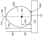
Fig. 1A is a perspective view of a circular shaped abrasive particle according to various embodiments.
Fig. 1B is a perspective view of the round shaped abrasive particle of fig. 1A rotated 90 degrees about the z-axis according to various embodiments.
Fig. 1C is a side view of a circular shaped abrasive particle in its stable position according to various embodiments.
Fig. 1D is a side view of the round shaped abrasive particle of fig. 1C with an apex offset from the z-axis according to various embodiments.
Fig. 1E is a side view of the round shaped abrasive particle of fig. 1C rotated 45 degrees about the z-axis according to various embodiments.
Fig. 2A is a perspective view of a twisted abrasive particle according to various embodiments.
Fig. 2B is a perspective view of the twisted abrasive particle of fig. 2A rotated 90 degrees about the z-axis according to various embodiments.
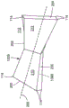
Fig. 2C is an end view of a twisted abrasive particle according to various embodiments.
Fig. 3A is a perspective view of curved abrasive particles resting on an area of a continuous non-planar surface, according to various embodiments.
Fig. 3B is a perspective view of curved abrasive particles resting on a sidewall, according to various embodiments.
Fig. 3C is a side view of curved abrasive particles resting on an area of a continuous non-planar surface, according to various embodiments.
Fig. 3D is a side view of the curved abrasive particle of fig. 3C rotated 90 degrees about the z-axis according to various embodiments.
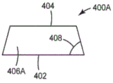
Fig. 4A-4B are schematic illustrations of shaped abrasive particles having a planar triangular shape according to various embodiments.
Fig. 5A-5E are schematic illustrations of shaped abrasive particles having a tetrahedral shape, according to various embodiments.
Fig. 6 is a screen shot illustrating the shaped abrasive particles of example 1 in their rest position according to various embodiments.
Detailed Description
Reference will now be made in detail to specific embodiments of the presently disclosed subject matter, examples of which are illustrated in the accompanying drawings. While the presently disclosed subject matter will be described in conjunction with the recited claims, it will be understood that the exemplary subject matter is not intended to limit the claims to the presently disclosed subject matter.
Throughout this document, values expressed in a range format should be interpreted in a flexible manner to include not only the numerical values explicitly recited as the limits of the range, but also to include all the individual numerical values or sub-ranges encompassed within that range as if each numerical value and sub-range is explicitly recited. For example, a range of "about 0.1% to about 5%" or "about 0.1% to 5%" should be interpreted to include not only about 0.1% to about 5%, but also include individual values (e.g., 1%, 2%, 3%, and 4%) and sub-ranges (e.g., 0.1% to 0.5%, 1.1% to 2.2%, 3.3% to 4.4%) within the indicated range. Unless otherwise indicated, the expression "about X to Y" has the same meaning as "about X to about Y". Likewise, unless otherwise indicated, the expression "about X, Y or about Z" has the same meaning as "about X, about Y, or about Z".
In this document, the terms "a", "an" or "the" are used to include one or more than one unless the context clearly indicates otherwise. The term "or" is used to refer to a non-exclusive "or" unless otherwise indicated. The expression "at least one of a and B" has the same meaning as "A, B or a and B". Also, it is to be understood that the phraseology or terminology employed herein, and not otherwise defined, is for the purpose of description only and not of limitation. Any use of section headings is intended to aid in the understanding of the document and should not be construed as limiting; information related to a section header may appear within or outside of that particular section.
In the methods described herein, various actions may be performed in any order, except when a time or sequence of operations is explicitly recited, without departing from the principles of the invention. Further, the acts specified may occur concurrently unless the express claim language implies that they occur separately. For example, the claimed act of performing X and the claimed act of performing Y may be performed simultaneously in a single operation, and the resulting process would fall within the literal scope of the claimed process.
As used herein, the term "about" can allow, for example, a degree of variability in the value or range, e.g., within 10%, within 5%, or within 1% of the stated value or limit of the range, and includes the exact stated value or range.
The term "substantially" as used herein refers to a majority or majority, such as at least about 50%, 60%, 70%, 80%, 90%, 95%, 96%, 97%, 98%, 99%, 99.5%, 99.9%, 99.99%, or at least about 99.999% or more, or 100%.
As used herein, the term "stable rest position" refers to a position that any shaped abrasive particle can achieve if it is subjected to no more than gravity and falls onto a planar surface. Each of the shaped abrasive particles described herein as 100A, 100B, and 100C is capable of achieving a stable rest position with at least one vertex oriented in a substantially upward direction.
Various embodiments of the present disclosure relate to shaped abrasive particles. Shaped abrasive particles disclosed herein comprise at least a first non-planar continuous surface and a second non-planar continuous surface. Although each surface is non-planar, each surface does not have a geometric inflection point of about 90 degrees that breaks the continuity of the corresponding non-planar surface. The first non-planar continuous surface and the second non-planar continuous surface are joined to each other by at least one sidewall or edge. One or more vertices of the shaped abrasive particles are formed by at least one sidewall or edge of the shaped abrasive particles. The shaped abrasive particles are configured such that, in a resting position on the substantially planar substrate, at least one vertex is oriented in a substantially upward direction relative to the planar substrate.
The shaped abrasive particles described herein can comprise any suitable material or mixture of materials. For example, the shaped abrasive particles may individually comprise a ceramic material or a polymeric material. If the shaped abrasive particles comprise a ceramic material, the ceramic material may comprise alpha alumina, sol-gel derived alpha alumina, or a mixture thereof. Other suitable materials include fused aluminum oxide, heat treated aluminum oxide, ceramic aluminum oxide, sintered aluminum oxide, silicon carbide material, titanium diboride, boron carbide, tungsten carbide, titanium carbide, diamond, cubic boron nitride, garnet, fused alumina-zirconia, ceria, zirconia, titania, or combinations thereof.
Some shaped abrasive particles may comprise a polymeric material and may be characterized as soft abrasive particles. The soft shaped abrasive particles described herein can individually comprise any suitable material or combination of materials. For example, the soft shaped abrasive particles can comprise the reaction product of a polymerizable mixture comprising one or more polymerizable resins. One or more polymerizable resins, such as a hydrocarbon-based polymerizable resin. Examples of such resins include those selected from the group consisting of: phenolic resins, urea-formaldehyde resins, urethane resins, melamine resins, epoxy resins, bismaleimide resins, vinyl ether resins, aminoplast resins (which may include pendant alpha, beta unsaturated carbonyl groups), acrylate resins, acrylated isocyanurate resins, acrylated urethane resins, acrylated epoxy resins, alkyl resins, polyester resins, drying oils, or mixtures thereof. The polymerizable mixture may include additional components such as plasticizers, acid catalysts, crosslinkers, surfactants, mild abrasives, pigments, catalysts, and antimicrobial agents.
Where multiple components are present in the polymerizable mixture, these components can comprise any suitable weight percent of the mixture. For example, the polymerizable resin may be in a range of about 35 wt% to about 99.9 wt%, about 40 wt% to about 95 wt%, or may be less than, equal to, or greater than about 35 wt%, 40 wt%, 41 wt%, 42 wt%, 43 wt%, 44 wt%, 45 wt%, 46 wt%, 47 wt%, 48 wt%, 49 wt%, 50 wt%, 51 wt%, 52 wt%, 53 wt%, 54 wt%, 55 wt%, 56 wt%, 57 wt%, 58 wt%, 59 wt%, 60 wt%, 61 wt%, 62 wt%, 63 wt%, 64 wt%, 65 wt%, 66 wt%, 67 wt%, 68 wt%, 69 wt%, 70 wt%, 71 wt%, 72 wt%, 73 wt%, 74 wt%, 75 wt%, 76 wt%, 77 wt%, 78 wt% of the polymerizable mixture, 79, 80, 81, 82, 83, 84, 85, 86, 87, 88, 89, 90, 91, 92, 93, 94, 95, 96, 97, 98, or about 99.9 wt%.
If present, the crosslinking agent can be in a range of about 2 wt% to about 60 wt%, about 5 wt% to about 10 wt% of the polymerizable mixture, or can be less than, equal to, or greater than about 2 wt%, 3 wt%, 4 wt%, 5 wt%, 6 wt%, 7 wt%, 8 wt%, 9 wt%, 10 wt%, 11 wt%, 12 wt%, 13 wt%, 14 wt%, or about 15 wt%. Examples of suitable crosslinking agents include those available under the tradename CYMEL 303LF from the knifing united states corporation of alpha lita, Georgia, USA (Allnex USA inc., Alpharetta, Georgia, USA); or a crosslinker available under the tradename CYMEL 385 from the knifing U.S. gmbh of alpha lita, georgia.
If present, the mild abrasive may be in the range of about 5 wt% to about 65 wt%, about 10 wt% to about 20 wt% of the polymerizable mixture, or may be less than, equal to, or greater than about 5 wt%, 6 wt%, 7 wt%, 8 wt%, 9 wt%, 10 wt%, 11 wt%, 12 wt%, 13 wt%, 14 wt%, 15 wt%, 16 wt%, 17 wt%, 18 wt%, 19 wt%, 20 wt%, 21 wt%, 22 wt%, 23 wt%, 24 wt%, 25 wt%, 26 wt%, 27 wt%, 28 wt%, 29 wt%, 30 wt%, 31 wt%, 32 wt%, 33 wt%, 34 wt%, 35 wt%, 36 wt%, 37 wt%, 38 wt%, 39 wt%, 40 wt%, 41 wt%, 42 wt%, 43 wt% of the polymerizable mixture, 44, 45, 46, 47, 48, 49, 50, 51, 52, 53, 54, 55, 56, 57, 58, 59, 60, 61, 62, 63, 64, or about 65 wt%. Examples of suitable mild abrasives include mild abrasives available under the trade designation MINSTRON 353TALC from American company for England porcelain TALC (Imerys Talc America, Inc., Three forms, Montana, USA) of Silivock, Monda; a mild abrasive available under the trade designation USG TERRA ALBA NO.1CALCIUM SULFATE from USG Corporation of Chicago, Ill. (USG Corporation, Chicago, Illinois, USA), USA; recycled glass (sand No. 40-70), silica, calcite, nepheline, syenite, calcium carbonate or mixtures thereof available from ESCA Industries ltd, Hatfield, Pennsylvania, USA of hattfield.
If present, the plasticizer can be in a range of about 5 wt% to about 40 wt%, about 10 wt% to about 15 wt%, or less than, equal to, or greater than about 5 wt%, 6 wt%, 7 wt%, 8 wt%, 9 wt%, 10 wt%, 11 wt%, 12 wt%, 13 wt%, 14 wt%, 15 wt%, 16 wt%, 17 wt%, 18 wt%, 19 wt%, 20 wt%, 21 wt%, 22 wt%, 23 wt%, 24 wt%, 25 wt%, 26 wt%, 27 wt%, 28 wt%, 29 wt%, 30 wt%, 31 wt%, 32 wt%, 33 wt%, 34 wt%, 35 wt%, 36 wt%, 37 wt%, 38 wt%, 39 wt%, or 40 wt% of the polymerizable mixture. Examples of suitable plasticizers include acrylic resins or styrene butadiene resins. Examples of acrylic resins include acrylic resins available under the trade name RHOPLEX GL-618 from Dow Chemical Company, Midland, Michigan, USA, Midland, Mich; acrylic resins available from luobo wet of victori, ohio, usa under the trade name HYCAR 2679; acrylic resins available from luobo wet of victori, ohio, under the trade name HYCAR 26796; polyether polyols available under the trade designation ARCOL LG-650 from Dow chemical company of Midland, Mich; or acrylic resins available from luobo inc of victori, ohio under the trade name HYCAR 26315. Examples of styrene butadiene resins include resins available from maillard Creek Polymers, inc., Charlotte, North Carolina, USA under the trade name roven 5900.
The acid catalyst, if present, can be in a range of from 1 wt% to about 20 wt%, about 5 wt% to about 10 wt%, or can be less than, equal to, or greater than about 1 wt%, 2 wt%, 3 wt%, 4 wt%, 5 wt%, 6 wt%, 7 wt%, 8 wt%, 9 wt%, 10 wt%, 11 wt%, 12 wt%, 13 wt%, 14 wt%, 15 wt%, 16 wt%, 17 wt%, 18 wt%, 19 wt%, or about 20 wt% of the polymerizable mixture. Examples of suitable acid catalysts include aluminum chloride solution or ammonium chloride solution.
If present, the surfactant can be in a range of about 0.001 wt% to about 15 wt%, about 5 wt% to about 10 wt% of the polymerizable mixture, or can be less than, equal to, or greater than about 0.001 wt%, 0.01 wt%, 0.5 wt%, 1 wt%, 2 wt%, 3 wt%, 4 wt%, 5 wt%, 6 wt%, 7 wt%, 8 wt%, 9 wt%, 10 wt%, 11 wt%, 12 wt%, 13 wt%, 14 wt%, or about 15 wt%. Examples of suitable surfactants include those available under the trade name GEMTEX SC-85-P from Innospec functional Chemicals of solvay, North Carolina (Innospec Performance Chemicals, Salisbury, North Carolina, USA); surfactants available under the trade name DYNOL 604 from Air Products and Chemicals, inc, Allentown, Pennsylvania, USA; a surfactant available from Dow chemical company of Midland, Mich.Mich.S.A. under the tradename ACRYSOL RM-8W; or surfactants available from the dow chemical company of midland, michigan under the tradename xiamater AFE 1520.
If present, the antimicrobial agent can be in a range of 0.5 wt% to about 20 wt%, about 10 wt% to about 15 wt%, or can be less than, equal to, or greater than about 0.5 wt%, 1 wt%, 2 wt%, 3 wt%, 4 wt%, 5 wt%, 6 wt%, 7 wt%, 8 wt%, 9 wt%, 10 wt%, 11 wt%, 12 wt%, 13 wt%, 14 wt%, 15 wt%, 16 wt%, 17 wt%, 18 wt%, 19 wt%, or about 20 wt% of the polymerizable mixture. Examples of suitable antimicrobial agents include zinc pyrithione.
The pigment, if present, can be in a range of about 0.1 wt% to about 10 wt%, about 3 wt% to about 5 wt% of the polymerizable mixture, or can be less than, equal to, or greater than about 0.1 wt%, 0.2 wt%, 0.4 wt%, 0.6 wt%, 0.8 wt%, 1 wt%, 1.5 wt%, 2 wt%, 2.5 wt%, 3 wt%, 3.5 wt%, 4 wt%, 4.5 wt%, 5 wt%, 5.5 wt%, 6 wt%, 6.5 wt%, 7 wt%, 7.5 wt%, 8 wt%, 8.5 wt%, 9 wt%, 9.5 wt%, or 10 wt%. Examples of suitable pigments include pigment dispersions available under the trade name SUNSPERSE BLUE 15 from Sun Chemical Corporation, Parsippany, New Jersey, USA, Parsippany, N.J.; pigment dispersions available under the tradename SUNSPERSE VIOLET 23 from solar chemical ltd, paspalnib, new jersey; pigment dispersions available under the name SUN BLACK from solar chemical ltd, pasipanib, new jersey; or PIGMENT dispersions available from Clariant ltd, Charlotte, North Carolina, USA under the trade name BLUE PIGMENT B2G, Charlotte, USA. The mixture of components may be polymerized by curing.
In addition to the materials already described, at least one magnetic material may be included within or coated onto the shaped abrasive particles. Examples of magnetic materials include iron; cobalt; nickel; is sold asVarious nickel and iron alloys of various grades of Permalloy (Permalloy); various alloys of iron, nickel and cobalt sold as iron-nickel-cobalt alloy (Fernico), Kovar, iron-nickel-cobalt alloy i (Fernico i), or iron-nickel-cobalt alloy ii (Fernico ii); various alloys of iron, aluminum, nickel, cobalt, and sometimes copper and/or titanium, sold as various grades of Alnico (Alnico); alloys of iron, silicon and aluminum (about 85:9:6 by weight) sold as iron-aluminum-silicon alloys; heusler alloys (e.g. Cu)2MnSn); manganese bismuthate (also known as manganese bismuthate (Bismanol)); rare earth magnetizable materials, such as gadolinium, dysprosium, holmium, europium oxides, and alloys of neodymium, iron, and boron (e.g., Nd)2Fe14B) And alloys of samarium and cobalt (e.g., SmCo)5);MnSb;MnOFe2O3;Y3Fe5O12;CrO2(ii) a MnAs; ferrites such as ferrite, magnetite; zinc ferrite; nickel ferrite; cobalt ferrite, magnesium ferrite, barium ferrite, and strontium ferrite; yttrium iron garnet; and the aforementioned compositions. In some embodiments, the magnetizable material is an alloy containing 8 to 12 wt.% aluminum, 15 to 26 wt.% nickel, 5 to 24 wt.% cobalt, up to 6 wt.% copper, up to 1 wt.% titanium, with the balance up to 100 wt.% of the material in total being iron. In some other embodiments, the magnetizable coating may be deposited on the abrasive particles 100A, 100B, 100C using a vapor deposition technique such as, for example, Physical Vapor Deposition (PVD), including magnetron sputtering.
The inclusion of these magnetizable materials may allow the shaped abrasive particles to respond to a magnetic field. Any of the shaped abrasive particles can comprise the same material or comprise different materials.
The apex of any of the shaped abrasive particles can have any suitable sharpness. One way to characterize the sharpness of the vertices is by measuring the radius of curvature of one or more vertices. In some embodiments, the radius of curvature of one or more vertices independently ranges from about 0.1 μm to about 200 μm, about 0.5 μm to 40 μm, less than, equal to, or greater than about 0.1 μm, 5 μm, 10 μm, 15 μm, 20 μm, 25 μm, 30 μm, 35 μm, 40 μm, 45 μm, 50 μm, 55 μm, 60 μm, 65 μm, 70 μm, 75 μm, 80 μm, 85 μm, 90 μm, 95 μm, 100 μm, 105 μm, 110 μm, 115 μm, 120 μm, 125 μm, 130 μm, 135 μm, 140 μm, 145 μm, 150 μm, 155 μm, 160 μm, 165 μm, 170 μm, 175 μm, 180 μm, 185 μm, 190 μm, 195 μm, 200 μm, 205 μm, 215 μm, 240 μm, 230 μm, 245 μm, 230 μm, 240 μm, 220 μm, 230 μm, 240 μm, 220 μm, and 240 μm, 250 μm, 255 μm, 260 μm, 265 μm, 270 μm, 275 μm, 280 μm, 285 μm, 290 μm, 295 μm, 300 μm, 305 μm, 310 μm, 315 μm, 320 μm, 325 μm, 330 μm, 335 μm, 340 μm, 345 μm, 350 μm, 355 μm, 360 μm, 365 μm, 370 μm, 375 μm, 380 μm, 385 μm, 390 μm, 395 μm, 400 μm, 405 μm, 410 μm, 415 μm, 420 μm, 425 μm, 430 μm, 435 μm, 440 μm, 445 μm, 450 μm, 455 μm, 460 μm, 465 μm, 470 μm, 480 μm, 485 μm, 495 μm, 475 μm, or about 500 μm.
The shaped abrasive particles can be designed to have any suitable thickness measured from the first non-planar surface to the second non-planar surface. For example, the thickness may be in the range of about 0.005mm to 5mm, about 0.02mm to 2mm, less than, equal to, or greater than about 0.005mm, 0.25mm, 0.50mm, 0.75mm, 1mm, 1.25mm, 1.50mm, 1.75mm, 2mm, 2.25mm, 2.50mm, 2.75mm, 3mm, 3.25mm, 3.50mm, 3.75mm, 4mm, 4.25mm, 4.50mm, 4.75mm, or about 5 mm. Additionally, any edge or sidewall can have any suitable length. For example, the length of the edge can be in the range of about 0.5 μm to about 2000 μm, about 150 μm to about 200 μm, or less than, equal to, or greater than about 0.5 μm, 50 μm, 100 μm, 150 μm, 200 μm, 250 μm, 300 μm, 350 μm, 400 μm, 450 μm, 500 μm, 550 μm, 600 μm, 650 μm, 700 μm, 750 μm, 800 μm, 850 μm, 900 μm, 950 μm, 1000 μm, 1050 μm, 1100 μm, 1150 μm, 1200 μm, 1250 μm, 1300 μm, 1350 μm, 1400 μm, 1450 μm, 1500 μm, 1550 μm, 1600 μm, 1650 μm, 1700 μm, 1750 μm, 1800 μm, 1850 μm, 1900 μm, 1950 μm, or about 2000 μm.
Fig. 1A-1E illustrate embodiments of a round shaped abrasive particle 100A. Fig. 1A-1E show many of the same components and are discussed simultaneously. As shown in fig. 1A-1E, the first continuous surface 102A and the second continuous surface 104A have curved profiles in which the cross-sectional shape (taken along the x-y direction) of the particle 100A generally conforms to a cylindrical shape. The generally cylindrical shape may conform to a symmetric circular shape or an asymmetric circular shape (e.g., oval or elliptical).
As shown in fig. 1A-1E, the curved profile includes a curved region 106 and a linear region 108. The bent region 106 can have a hemispherical shape, which can comprise about 5% to about 70% surface area, about 25% to about 50% surface area, less than, equal to, or greater than about 5% surface area, 10% surface area, 15% surface area, 20% surface area, 25% surface area, 30% surface area, 35% surface area, 40% surface area, 45% surface area, 50% surface area, 55% surface area, 60% surface area, 65% surface area, or about 70% surface area of the shaped abrasive particle 100A. Linear region 108 may comprise about 5% surface area to about 70% surface area, about 25% surface area to about 50% surface area, less than, equal to, or greater than about 5% surface area, 10% surface area, 15% surface area, 20% surface area, 25% surface area, 30% surface area, 35% surface area, 40% surface area, 45% surface area, 50% surface area, 55% surface area, 60% surface area, 65% surface area, or about 70% surface area of shaped abrasive particle 100A.
Shaped abrasive particle 100A is designed such that bottom end 110 is located within bend region 106. In the stable rest position, the bottom end 110 is in contact with the base 112. The substrate 112 may be a backing for an abrasive article. In these embodiments, the substrate 112 may be flexible or rigid. Examples of suitable materials for forming the flexible backing include polymeric films, metal foils, woven fabrics, knitted fabrics, paper, vulcanized fiber, staple fiber, continuous fiber, nonwoven, foams, wire mesh, laminates, organic materials (such as wood, leather), and combinations thereof. The substrate 112 may be shaped to allow the abrasive article to be in the form of a sheet, disc, belt, pad, or roll. In some embodiments, the substrate 112 may be sufficiently flexible to allow the abrasive article to be shaped into a loop to prepare an abrasive belt that can be run on a suitable grinding apparatus.
To help ensure that the bottom end 110 is in contact with the substrate 112, the shaped abrasive particle 100A may be designed such that the center of gravity is located within the bending region 106. While the center of gravity is located within the flexion region 106, the geometric center of gravity need not be located within the flexion region 106. Shaped abrasive particle 100A may be designed such that the geometric center of particle 100A may be located in curved region 106, in linear region 108, or at the interface between the two.
The apex 114 is located at a top end 116 of the shaped abrasive particle 100A opposite the bottom end 110. Apex 114 is formed by sidewalls 119 that engage surfaces 102A and 104A. As shown, the shaped abrasive particle 100A includes two apexes 114. However, in other embodiments, the shaped abrasive particle 100A may include as few as one apex 114 or any plurality of apexes 114.
As described herein, in the rest position, at least one of the vertices 114 is oriented in a substantially upward direction relative to the planar base. The degree to which the individual vertices are oriented in an upward direction may be characterized by a distance 152 measured from any of the vertices 114 to the surface of the base 112 that is greater than a distance measured from the center of gravity 150 to the surface of the base 112. In some embodiments, shaped abrasive particle 100A may have apex 114 offset from being oriented in a substantially vertical position. This is illustrated in fig. 1D, where the distance 152 from the apex 114 to the base 112 is greater than the distance 154 from the center of gravity to the base 112, but is only about 95%, 90%, 85%, 80%, or 75% of the distance 152 from the apex 114 to the base 112 when the particle is in a fully upright position. The value of the distance 152 from the apex 114 to the base 112 may be any suitable value, for example the distance 152 between the apex 114 and the base 112 may be greater than about 101% of the distance 154 from the center of gravity 150 to the base 112, or within the range of about 101% to about 10,000% of the distance to the entire distance from the apex 114 to the base 112 when the particle is in a fully upright position.
In addition to controlling the degree to which the apex 114 points upward, the shaped abrasive particle 100A may be rotated on the substrate 112 about the line 120 to any suitable degree. For example, as shown in fig. 1E, the shaped abrasive particle 100A is rotated about 45 degrees about the line 120. Although a rotation of about 45 degrees is shown, the shaped abrasive particle 100A can be rotated by any suitable amount between 0 degrees and 360 degrees, such as about 10 degrees to about 170 degrees, about 45 degrees to about 135 degrees, about 70 degrees to about 110 degrees, less than, equal to, or greater than about 5 degrees, 10 degrees, 15 degrees, 20 degrees, 25 degrees, 30 degrees, 35 degrees, 40 degrees, 45 degrees, 50 degrees, 55 degrees, 60 degrees, 65 degrees, 70 degrees, 75 degrees, 80 degrees, 85 degrees, 90 degrees, 95 degrees, 100 degrees, 105 degrees, 110 degrees, 115 degrees, 120 degrees, 125 degrees, 130 degrees, 135 degrees, 140 degrees, 145 degrees, 150 degrees, 155 degrees, 160 degrees, 165 degrees, or about 170 degrees.
Fig. 2A-2C illustrate a shaped abrasive particle 100B. As shown in fig. 2A-2C, the shaped abrasive particle 100B is formed from a first non-planar continuous surface 102B and a second non-planar continuous surface 104B. Surfaces 102B and 104B are joined by sidewalls 200, 202, 204, and 206, each forming two vertices 114 at the intersection therebetween.
Shaped abrasive particle 100B is twisted about longitudinal axis 208 to form first region 210 and second region 212. The twisting results in a dihedral angle between the first region 210 and the second region 212 in a range from about 5 degrees to about 170 degrees, about 20 degrees to about 90 degrees, less than, equal to, or greater than about 5 degrees, 10 degrees, 15 degrees, 20 degrees, 25 degrees, 30 degrees, 35 degrees, 40 degrees, 45 degrees, 50 degrees, 55 degrees, 60 degrees, 65 degrees, 70 degrees, 75 degrees, 80 degrees, 85 degrees, 90 degrees, 95 degrees, 100 degrees, 105 degrees, 110 degrees, 115 degrees, 120 degrees, 125 degrees, 130 degrees, 135 degrees, 140 degrees, 145 degrees, 150 degrees, 155 degrees, 160 degrees, 165 degrees, or about 170 degrees.
As shown in fig. 2A and 2B, each of first region 210 and second region 212 comprises about 50% of the total surface area of shaped abrasive particle 100B. Thus, the change in curvature of the first non-planar continuous surface 102B and the second non-planar continuous surface 104B is located at the midpoint of the shaped abrasive particle 100B as measured along the axis 208. However, in additional embodiments of the shaped abrasive particle 100B, the first region 210 and the second region 212 may independently range from about 5% surface area to about 95% surface area, about 25% surface area to about 50% surface area, less than, equal to, or greater than about 5% surface area, 10% surface area, 15% surface area, 20% surface area, 25% surface area, 30% surface area, 35% surface area, 40% surface area, 45% surface area, 50% surface area, 55% surface area, 60% surface area, 65% surface area, 70% surface area, 75% surface area, 80% surface area, 85% surface area, 90% surface area, or about 95% surface area of the shaped abrasive particle 100B.
Shaped abrasive particles 100B can conform to one of a number of different shapes. The shape may be determined by characterizing the cross-sectional shape of the shaped abrasive particle 100B taken along the central axis 208. For example, the first region 210 and the second region 212 may independently include a quadrilateral cross-sectional shape. The quadrilateral cross-sectional shape may conform substantially to a square, rectangle, or trapezoid. Alternatively, the first region 210 and the second region 212 may independently have a substantially triangular cross-sectional shape. The triangular shape may substantially conform to an equilateral triangle, a right-angled triangle, a scalar triangle, an isosceles triangle, an acute triangle, or an obtuse triangle. In some embodiments of shaped abrasive particle 100B, the cross-sectional area values may differ throughout the length of shaped abrasive particle 100B (measured along axis 108). In other embodiments, the cross-sectional shape may conform to any higher order polygonal shape.
As shown in fig. 2A-2C, in the resting position, three of the apexes 114 are in contact with the base 112. This causes at least one vertex 114 to point in a substantially upward direction. The substantially upward direction is shown in FIG. 2C, where the distance 252 from the apex 114 to the base 112 is greater than the distance 254 from the center of gravity 250 to the base 112. In addition, as shown in FIG. 2C, line 120 is perpendicular to base 112 and passes through upwardly directed cusp apex 114. Another line 122 passes through the same apex 114 of the tip and the apex in contact with the base. The apex 114 in contact with the base 112 is in the same region of the tip apex 114 (in either region 210 or region 212). Angle 118 is formed between line 120 and line 122. The substantially upward direction is shown in fig. 2C, where angle 118 is between zero and 85 degrees. In some embodiments, shaped abrasive particle 100B may have apex 114 offset from being oriented in a perfectly vertical position. The value of angle 118 can be any suitable value, for example, angle 118 can be in a range of about 1 degree to about 85 degrees, about 1 degree to about 45 degrees, less than, equal to about 1 degree, 5 degrees, 10 degrees, 15 degrees, 20 degrees, 25 degrees, 30 degrees, 35 degrees, 40 degrees, 45 degrees, 50 degrees, 55 degrees, 60 degrees, 65 degrees, 70 degrees, 75 degrees, 80 degrees, or about 85 degrees.
In addition to controlling the degree to which the apex 114 points upward, the shaped abrasive particle 100B may be rotated on the substrate 112 to any suitable degree about the line 120 or any other line perpendicular to the substrate 112 and passing through the shaped abrasive particle 100B. For example, the shaped abrasive particles 100B may be rotated about the line 120 by any suitable amount, such as about 5 degrees to about 185 degrees, about 45 degrees to about 135 degrees, about 70 degrees to about 110 degrees, less than, equal to, or greater than about 5 degrees, 10 degrees, 15 degrees, 20 degrees, 25 degrees, 30 degrees, 35 degrees, 40 degrees, 45 degrees, 50 degrees, 55 degrees, 60 degrees, 65 degrees, 70 degrees, 75 degrees, 80 degrees, 85 degrees, 90 degrees, 95 degrees, 100 degrees, 105 degrees, 110 degrees, 115 degrees, 120 degrees, 125 degrees, 130 degrees, 135 degrees, 140 degrees, 145 degrees, 150 degrees, 155 degrees, 160 degrees, 165 degrees, or about 185 degrees. Although one resting position is shown in which the first non-planar continuous surface 102B is oriented away from the substrate 112, the shaped abrasive particle 100B may also be oriented in a second resting position in which the second non-planar continuous surface 104B is oriented away from the substrate 112.
Fig. 3A-3C illustrate a shaped abrasive particle 100C. As shown, the shaped abrasive particle 100C includes a first continuous non-planar surface 102C and a second continuous non-planar surface 104C. Surfaces 102C and 104C are joined by sidewalls 200, 202, 204, and 206, each forming one or two vertices 114 at the intersection therebetween.
Shaped abrasive particle 100C has bends to form first region 310 and second region 312. The bending results in a dihedral angle measured between the first region 310 and the second region 312. The dihedral angles are in a range of about 30 degrees to about 179 degrees, about 45 degrees to about 90 degrees, less than, equal to, or greater than about 45 degrees, 50 degrees, 60 degrees, 75 degrees, 80 degrees, 85 degrees, 90 degrees, 95 degrees, 100 degrees, 105 degrees, 110 degrees, 115 degrees, 120 degrees, 125 degrees, 130 degrees, 135 degrees, 140 degrees, 145 degrees, 150 degrees, 155 degrees, 160 degrees, 165 degrees, 170 degrees, 175 degrees, or about 179 degrees with respect to each other. The radius of curvature measured across the bend may be in the range of about 0.01mm to 10 mm.
As shown in fig. 3A and 3B, each of the first and second regions 310, 312 comprises about 50% of the total surface area of the shaped abrasive particle 100C. Thus, the inflection points on the first non-planar continuous surface 102C and the second non-planar continuous surface 104C are located at the midpoint of the shaped abrasive particle 100C. However, in additional embodiments of the shaped abrasive particle 100C, the first region 310 and the second region 312 may independently range from about 5% surface area to about 95% surface area, about 25% surface area to about 50% surface area, less than, equal to, or greater than about 5% surface area, 10% surface area, 15% surface area, 20% surface area, 25% surface area, 30% surface area, 35% surface area, 40% surface area, 45% surface area, 50% surface area, 55% surface area, 60% surface area, 65% surface area, 70% surface area, 75% surface area, 80% surface area, 85% surface area, 90% surface area, or about 95% surface area of the shaped abrasive particle 100C.
Shaped abrasive particles 100C may conform to one of a number of different shapes. The shape can be determined by characterizing the cross-sectional shape of the shaped abrasive particle 100C. For example, the first region 310 and the second region 312 may independently comprise a quadrilateral cross-sectional shape. For example, the quadrilateral cross-sectional shape may substantially conform to a square, rectangle, or trapezoid. Alternatively, the first region 310 and the second region 312 may independently have a substantially triangular cross-sectional shape. The triangular shape may substantially conform to an equilateral triangle, a right-angled triangle, a scalar triangle, an isosceles triangle, an acute triangle, or an obtuse triangle. The cross-sectional shape may also conform to any suitable higher-order polygon, such as a pentagon, hexagon, heptagon, or octagon. The cross-sectional shape of the first region 310 or the second region 312 may also be a composite of different polygons, such as a triangle joined to a rectangle along its edges. In some embodiments of the shaped abrasive particle 300C, the cross-sectional area value may vary throughout the length of the shaped abrasive particle 300C. The size and shape of the first region 310 and the second region 312 may be substantially equivalent or non-equivalent.
As shown in fig. 3A and 3B, the shaped abrasive particles 100C may be disposed on the substrate 112 in a plurality of different rest positions. For example, in fig. 3A, the second region 312 is in contact with the substrate 112. In alternative embodiments, the first region 310 may be in contact with the substrate 112. In fig. 3B, sidewalls 200 and 206 are in contact with base 112. In alternative embodiments, the sidewalls 202 and 204 may be in contact with the substrate 112. At least one of the vertices 114 may be oriented in a substantially upward direction in any possible resting position. This causes at least one vertex 114 to point in a substantially upward direction. In the substantially upward direction shown in FIG. 3C, a distance 352 measured from the apex 114 to the base 112 is greater than a distance 354 measured from the center of gravity 350 to the base surface 112. In some embodiments, shaped abrasive particle 100C may have apex 114 offset from being oriented in a fully vertical position, wherein the distance from apex 114 to base 112 is greater than the distance from the center of gravity to base 112, but is only about 99%, 95%, 90%, 85%, 80%, 75%, or less of the distance from apex 114 to base 112 when the particle is in a fully vertical position.
In addition to controlling the degree to which the apex 114 points upward, the shaped abrasive particle 100C may be rotated on the base 112 to any suitable degree about a line 120 or any other line perpendicular to the base 112 and passing through the shaped abrasive particle 100C. For example, the shaped abrasive particle 100C may be rotated about the line 120 by any suitable amount, such as about 5 degrees to about 185 degrees, about 45 degrees to about 135 degrees, about 70 degrees to about 110 degrees, less than, equal to, or greater than about 5 degrees, 10 degrees, 15 degrees, 20 degrees, 25 degrees, 30 degrees, 35 degrees, 40 degrees, 45 degrees, 50 degrees, 55 degrees, 60 degrees, 65 degrees, 70 degrees, 75 degrees, 80 degrees, 85 degrees, 90 degrees, 95 degrees, 100 degrees, 105 degrees, 110 degrees, 115 degrees, 120 degrees, 125 degrees, 130 degrees, 135 degrees, 140 degrees, 145 degrees, 150 degrees, 155 degrees, 160 degrees, 165 degrees, 170 degrees, 175 degrees, 180 degrees, or about 185 degrees.
Shaped abrasive particles 100A, 100B, or 100C can be formed in a number of suitable ways, for example, shaped abrasive particles 100A, 100B, or 100C can be prepared according to a multi-operation process. The process can be carried out using any material or precursor dispersion material. Briefly, for embodiments in which the shaped abrasive particle 100A, 100B, or 100C is a monolithic ceramic particle, the method may include the operations of: preparing a seeded or unseeded precursor dispersion that can be converted to the corresponding (e.g., boehmite sol-gel that can be converted to alpha alumina); filling one or more mold cavities having a desired profile of shaped abrasive particles 100A, 100B, or 100C with the precursor dispersion; drying the precursor dispersion to form a shaped abrasive particle precursor; removing the precursor shaped abrasive particles 100A, 100B, or 100C from the mold cavity; calcining a precursor of shaped abrasive particle 100A, 100B, or 100C to form a calcined precursor of shaped abrasive particle 100A, 100B, or 100C; and then sintering the calcined shaped abrasive particle 100A, 100B, or 100C precursor to form the shaped abrasive particle 100A, 100B, or 100C. The method will now be described in more detail in the context of alpha-alumina containing shaped abrasive particles 100A, 100B, or 100C. In other embodiments, the mold cavity can be filled with melamine to form melamine shaped abrasive particles.
The method can include an operation of providing a seeded or unseeded precursor dispersion that can be converted to a ceramic. In the example of seeding the precursor, the precursor may be seeded with iron oxide (e.g., FeO). The precursor dispersion may comprise a liquid as the volatile component. In one example, the volatile component is water. The dispersion may contain a sufficient amount of liquid to make the viscosity of the dispersion low enough to fill the mold cavity and replicate the mold surface, but not so much liquid as to result in excessive costs for subsequent removal of the liquid from the mold cavity. In one example, the precursor dispersion comprises 2 to 90 wt% of particles capable of being converted to ceramic, such as alumina monohydrate (boehmite) particles, and at least 10 wt%, or 50 to 70 wt%, or 50 to 60 wt% of a volatile component, such as water. Conversely, in some embodiments, the precursor dispersion comprises from 30 wt% to 50 wt% or from 40 wt% to 50 wt% solids.
Examples of suitable precursor dispersions include zirconia sols, vanadia sols, ceria sols, alumina sols, and combinations thereof. Suitable alumina dispersions include, for example, boehmite dispersions as well as other alumina hydrate dispersions. Boehmite can be prepared by known techniques or is commercially available. Examples of commercially available boehmite include products sold under the trade names "DISPERAL" and "DISPAL" both available from Sasol North America, Inc., or under the trade name "HIQ-40" available from BASF. These alumina monohydrate are relatively pure; that is, they contain relatively few, if any, other hydrate phases in addition to a monohydrate, and have a high surface area.
The physical properties of the resulting shaped abrasive particles 100A, 100B, or 100C may generally depend on the type of material used in the precursor dispersion. As used herein, a "gel" is a three-dimensional network of solids dispersed in a liquid.
The precursor dispersion may comprise a modifying additive or a precursor of a modifying additive. Modifying additives may be used to enhance certain desired characteristics of the abrasive particles or to increase the efficiency of subsequent sintering steps. The modifying additive or precursor of the modifying additive may be in the form of a soluble salt, such as a water soluble salt. They may include metal-containing compounds and may be precursors of oxides of magnesium, zinc, iron, silicon, cobalt, nickel, zirconium, hafnium, chromium, yttrium, praseodymium, samarium, ytterbium, neodymium, lanthanum, gadolinium, cerium, dysprosium, erbium, titanium, and mixtures thereof. The specific concentrations of these additives that may be present in the precursor dispersion may vary.
The introduction of the modifying additive or modifying additive precursor can result in gelation of the precursor dispersion. The precursor dispersion can also be gelled by: the heating is carried out over a period of time so as to reduce the liquid content of the dispersion by evaporation. The precursor dispersion may further comprise a nucleating agent. Nucleating agents suitable for use in the present disclosure may include fine particles of alpha alumina, alpha iron oxide or precursors thereof, titanium dioxide and titanates, chromium oxide, or any other substance that nucleates the transformation. If a nucleating agent is used, it should be present in sufficient quantity to convert the alpha alumina.
A peptizing agent can be added to the precursor dispersion to produce a more stable hydrosol or colloidal precursor dispersion. Suitable peptizing agents are monoprotic acids or acidic compounds, such as acetic acid, hydrochloric acid, formic acid and nitric acid. Polyprotic acids may also be used, but they may rapidly gel the precursor dispersion, making it difficult to handle or introduce additional components. Certain commercial sources of boehmite contain an acid titer (e.g., absorbed formic or nitric acid) that aids in the formation of a stable precursor dispersion.
The precursor dispersion can be formed by any suitable means; for example, in the case of a sol-gel alumina precursor, it can be formed by simply mixing alumina monohydrate with water containing a peptizing agent, or by forming an alumina monohydrate slurry with added peptizing agent.
An anti-foaming agent or other suitable chemical may be added to reduce the tendency of air bubbles or entrained air to form during mixing. Other chemicals such as wetting agents, alcohols or coupling agents may be added if desired. A foaming agent may be added to form bubbles in order to adjust the density of the particles.
Further operations may include providing a mold having at least one mold cavity, or a plurality of cavities formed in at least one major surface of the mold. In some examples, the mold is formed as a production tool, which may be an applicator roll such as a belt, sheet, continuous web, rotary gravure roll, sleeve mounted on an applicator roll, or die. In one example, the production tool may comprise a polymeric material. Examples of suitable polymeric materials include thermoplastics such as polyesters, polycarbonates, poly (ether sulfone), poly (methyl methacrylate), polyurethanes, polyvinyl chloride, polyolefins, polystyrene, polypropylene, polyethylene, or combinations thereof, or thermosets. In one example, the entire mold is made of a polymeric or thermoplastic material. In another example, the surfaces of the mold (such as the surfaces of the plurality of cavities) that are contacted with the precursor dispersion when the precursor dispersion is dried comprise a polymeric or thermoplastic material, and other portions of the mold can be made of other materials. By way of example, a suitable polymer coating may be applied to the metal mold to alter its surface tension characteristics. In some examples, the mold or production tool is a two-part tool, wherein one part comprises the recess and the second part comprises the protrusion at least partially filling the recess. This can be used to form shaped abrasive particles 100A, 100B, or 100C.
Polymeric or thermoplastic production tools can be replicated from a metal master tool. The master tool can have the inverse pattern desired for the production tool. The master tool can be made in the same manner as the production tool. In one example, the master tool is made of metal (e.g., nickel) and diamond turned. In one example, the master tool is formed at least in part using stereolithography techniques. The polymeric sheet material can be heated along with the master tool such that the master tool pattern is imprinted on the polymeric material by pressing the two together. A polymer or thermoplastic material can also be extruded or cast onto the master tool and then pressed. The thermoplastic material is cooled to harden it, thereby producing the production tool. If a thermoplastic production tool is utilized, care should be taken not to generate excessive heat, which can deform the thermoplastic production tool, thereby limiting its life.
The cavity is accessible from an opening in either the top or bottom surface of the mold. In some examples, the cavity may extend through the entire thickness of the mold. Alternatively, the cavity may extend only a portion of the thickness of the mold. In one example, the top surface is substantially parallel to the bottom surface of the mold, wherein the cavities have a substantially uniform depth. At least one side of the mold, i.e., the side in which the cavity is formed, may remain exposed to the ambient atmosphere during the step of removing the volatile component.
The cavities have a particular three-dimensional shape to produce shaped abrasive particles 100A, 100B, or 100C. The cavity depth dimension is equal to the vertical distance from the top surface to the lowest point on the bottom surface. The depth of a given cavity may be uniform or may vary along its length and/or width. The cavities of a given mold may have the same shape or different shapes.
Additional operations involve filling the cavities in the mold with the precursor dispersion (e.g., filling by conventional techniques). In some examples, a knife roll coater or a vacuum slot die coater may be used. If desired, a release agent may be used to aid in the removal of the particles from the mold. Examples of release agents include oils (such as peanut oil or mineral oil, fish oil), silicones, polytetrafluoroethylene, zinc stearate, and graphite. Generally, dehydration in a liquid such as water or alcohol is carried outA molding agent such as peanut oil is applied to the surface of the production mold in contact with the precursor dispersion so that when demolding is desired, about 0.1mg/in is present per unit area of mold2(0.6mg/cm2) To about 3.0mg/in2(20mg/cm2) Or about 0.1mg/in2(0.6mg/cm2) To about 5.0mg/in2(30mg/cm2) The mold release agent of (1). In some embodiments, the top surface of the mold is coated with the precursor dispersion. The precursor dispersion can be pumped onto the top surface.
In a further operation, a doctor blade or smoothing bar may be used to completely press the precursor dispersion into the cavity of the mold. The remainder of the precursor dispersion that does not enter the cavity can be removed from the top surface of the mold and recycled. In some examples, a small portion of the precursor dispersion may remain on the top surface, and in other examples, the top surface is substantially free of dispersion. The pressure applied by the doctor blade or smoothing bar may be less than 100psi (0.6MPa), or less than 50psi (0.3MPa), or even less than 10psi (60 kPa). In some examples, the exposed surface of the precursor dispersion does not substantially extend beyond the top surface.
In those instances where it is desirable to form a plane of shaped abrasive particles using the exposed surfaces of the cavities, it may be desirable to overfill the cavities (e.g., using a micro-nozzle array) and slowly dry the precursor dispersion.
A further operation involves removing volatile components to dry the dispersion. Volatile components can be removed by a rapid evaporation rate. In some examples, the removal of the volatile component by evaporation is performed at a temperature above the boiling point of the volatile component. The upper limit of the drying temperature generally depends on the material from which the mold is made. For polypropylene molds, the temperature should be below the melting point of the plastic. In one example, the drying temperature may be about 90 ℃ to about 165 ℃, or about 105 ℃ to about 150 ℃, or about 105 ℃ to about 120 ℃ for an aqueous dispersion containing about 40% to 50% solids and a polypropylene mold. Higher temperatures can lead to improved production speeds, but can also lead to degradation of the polypropylene mold, thereby limiting its useful life as a mold.
In some examples, the mold may be twisted before the precursor is dried. This can impart a twist or bend in the shaped abrasive particles 100B and 100C.
During drying, the precursor dispersion shrinks, typically causing retraction from the chamber walls. For example, if the cavity has planar walls, the resulting shaped abrasive particle 100A, 100B, or 100C can often have at least three concave major sides. It has now been found that by recessing the cavity walls (and thus increasing the cavity volume), a shaped abrasive particle 100A, 100B, or 100C having at least three substantially planar major sides can be obtained. The extent of dishing generally depends on the solids content of the precursor dispersion.
Additional operations involve removing the resulting precursor shaped abrasive particles 100A, 100B, or 100C from the mold cavity. The precursor shaped abrasive particles 100A, 100B, or 100C may be removed from the cavity by using the following process: the particles are removed from the mold cavity using gravity, vibration, ultrasonic vibration, vacuum or pressurized air methods on the mold alone or in combination.
The precursor shaped abrasive particles 100A, 100B, or 100C can be further dried outside the mold. This additional drying step is not necessary if the precursor dispersion is dried to the desired extent in the mold. However, in some cases, it may be economical to employ this additional drying step to minimize the residence time of the precursor dispersion in the mold. The precursor shaped abrasive particles 100A, 100B, or 100C will be dried at a temperature of 50 ℃ to 160 ℃, or 120 ℃ to 150 ℃, for 10 minutes to 480 minutes, or 120 minutes to 400 minutes.
Additional operations involve calcining the precursor shaped abrasive particles 100A, 100B, or 100C. During calcination, substantially all volatile materials are removed and the various components present in the precursor dispersion are converted to metal oxides. Typically, the precursor shaped abrasive particles 100A, 100B, or 100C are heated to a temperature of 400 ℃ to 800 ℃ and maintained within this temperature range until the free water and 90 wt.% or more of any bound volatile species are removed. In an optional step, it may be desirable to introduce the modifying additive by an impregnation process. The water-soluble salt may be introduced by injecting it into the pores of the calcined precursor shaped abrasive particle 100A, 100B, or 100C. The shaped abrasive particle 100 precursor is then pre-fired again.
Additional operations may involve sintering the calcined precursor of shaped abrasive particle 100A, 100B, or 100C to form particle 100A, 100B, or 100C. However, in some examples where the precursor comprises a rare earth metal, sintering may not be necessary. Prior to sintering, the calcined precursor of the shaped abrasive particle 100A, 100B, or 100C is not fully densified and thus lacks the hardness needed to function as the shaped abrasive particle 100A, 100B, or 100C. Sintering is performed by heating the calcined precursor of shaped abrasive particles 100A, 100B, or 100C to a temperature of 1000 ℃ to 1650 ℃. To achieve this degree of conversion, the length of time that the calcined precursor shaped abrasive particle 100A, 100B, or 100C can be exposed to the sintering temperature depends on a variety of factors, but can be from five seconds to 48 hours.
In another embodiment, the duration of the sintering step is in the range of one minute to 90 minutes. After sintering, the shaped abrasive particles 100A, 100B, or 100C can have a Vickers hardness of 10GPa (gigapascal), 16GPa, 18GPa, 20GPa, 25GPa, or greater.
The process can be modified using additional operations such as rapid heating of the material from the calcination temperature to the sintering temperature and centrifuging the precursor dispersion to remove sludge and/or waste. Furthermore, the method can be modified, if desired, by combining two or more of the method steps.
In further embodiments, the shaped abrasive particles 100A, 100B, or 100C may be formed by additive manufacturing.
Any of the shaped abrasive particles 100A, 100B, 100C, or mixtures thereof, may be included in an abrasive article, such as a coated abrasive article. The coated abrasive article may be formed as a belt, disc, or sheet. The coated abrasive article includes a substrate or backing 112. Shaped abrasive particles 100A, 100B, or 100C are adhered to backing or substrate 112 by a make coat. Shaped abrasive particles 100A, 100B, or 100C may also be adhered to a make layer by a size layer or an optional size layer. In some embodiments, the shaped abrasive particles 100A, 100B, or 100C are in full or partial contact with the make coat. Although a coated abrasive article is described, any of the shaped abrasive particles 100A, 100B, or 100C may be included in a bonded abrasive article or a woven abrasive article.
The make or size layers may comprise any suitable adhesive material or resin. For example, the make layer, size layer, or both may include a phenolic resin, an epoxy resin, a urea-formaldehyde resin, an acrylate resin, an aminoplast resin, a melamine-formaldehyde resin, an acrylic-modified epoxy resin, a urethane resin, or mixtures thereof. The make coat, size coat, or both may include additives such as fillers (e.g., calcium carbonate, silica, talc, clay, calcium metasilicate, dolomite, aluminum sulfate, or mixtures thereof), grinding aids, wetting agents, surfactants, dyes, pigments, coupling agents, adhesion promoters, or mixtures thereof.
Shaped abrasive particles 100A, 100B, or 100C may be present in the abrasive article as the only shaped abrasive particles, however, in other embodiments, shaped abrasive particles 100A, 100B, or 100C may be present as a blend of abrasive particles, which may include the same material or different materials. For example, some abrasive articles may include a blend, wherein the shaped abrasive particles 100A, 100B, or 100C are present in a range from about 5 wt% to about 99 wt% of the blend, from about 50 wt% to about 95 wt% of the blend, less than, equal to, or greater than about 5 wt%, 10 wt%, 15 wt%, 20 wt%, 25 wt%, 30 wt%, 35 wt%, 40 wt%, 45 wt%, 50 wt%, 55 wt%, 60 wt%, 65 wt%, 70 wt%, 75 wt%, 80 wt%, 85 wt%, 90 wt%, 95 wt%, or about 95 wt% of the blend.
In some embodiments, the blend of abrasive particles may comprise abrasive particles shaped as equilateral triangles conforming to a truncated pyramid. As shown in fig. 4A and 4B, wherein the soft shaped abrasive particle 400 comprises a truncated regular triangular pyramid defined by a triangular base 402, a triangular tip 404, and a plurality of inclined sides 406A, 406B, 406C connecting the triangular base 402 (shown as an equilateral triangle, although inequalities, obtuse angles, isosceles and right triangles are also possible) and the triangular tip 404. Tilt angle 408A is the dihedral angle formed by side 406A intersecting triangular base 402. Similarly, angles of inclination 408B and 408C (neither shown) correspond to dihedral angles formed by sides 406B and 406C, respectively, intersecting triangular base 402. For the shaped abrasive particle 400, all of the tilt angles have equal values. In some embodiments, the side edges 406A, 406B, and 406C have an average radius of curvature in a range from about 0.05 μm to about 80 μm, from about 10 μm to about 60 μm, or less than, equal to, or greater than about 0.05 μm, 5 μm, 10 μm, 15 μm, 20 μm, 25 μm, 30 μm, 35 μm, 40 μm, 45 μm, 50 μm, 55 μm, 60 μm, 65 μm, 70 μm, 75 μm, or about 80 μm.
In the embodiment shown in fig. 4A and 4B, the sides 406A, 406B, 406C are of equal size and form dihedral angles with the triangular base 402 of about 82 degrees (corresponding to an oblique angle of 82 degrees). However, it should be understood that other dihedral angles (including 90 degrees) may be used. For example, the dihedral angle between the base and each of the sides can independently range from 45 degrees to 90 degrees (e.g., 70 degrees to 90 degrees or 75 degrees to 85 degrees). The edges connecting sides 406, base 402, and top 404 may have any suitable length. For example, the length of the edge can be in the range of about 0.5 μm to about 2000 μm, about 150 μm to about 200 μm, or less than, equal to, or greater than about 0.5 μm, 50 μm, 100 μm, 150 μm, 200 μm, 250 μm, 300 μm, 350 μm, 400 μm, 450 μm, 500 μm, 550 μm, 600 μm, 650 μm, 700 μm, 750 μm, 800 μm, 850 μm, 900 μm, 950 μm, 1000 μm, 1050 μm, 1100 μm, 1150 μm, 1200 μm, 1250 μm, 1300 μm, 1350 μm, 1400 μm, 1450 μm, 1500 μm, 1550 μm, 1600 μm, 1650 μm, 1700 μm, 1750 μm, 1800 μm, 1850 μm, 1900 μm, 1950 μm, or about 2000 μm.
In some embodiments, the blend may include abrasive particles shaped as tetrahedral abrasive particles. As shown in fig. 5A-5E, the shaped abrasive particles 500 are shaped as regular tetrahedrons. As shown in fig. 5A, the shaped abrasive particle 500A has four faces (520A, 522A, 524A, and 526A) joined by six edges (530A, 532A, 534A, 536A, 538A, and 539A) that terminate in four vertices (540A, 542A, 544A, and 546A). Each of the faces contacts the other three of the faces at the edges. Although a regular tetrahedron (e.g., having six equal sides and four faces) is depicted in fig. 5A, it will be recognized that other shapes are also permissible. For example, tetrahedral abrasive particle 500 may be shaped as irregular tetrahedrons (e.g., edges having different lengths).
Referring now to fig. 5B, a shaped abrasive particle 500B has four faces (520B, 522B, 524B, and 526B) joined by six edges (530B, 532B, 534B, 536B, 538B, and 539B) that terminate in four vertices (540B, 542B, 544B, and 546B). Each of the faces is concave and contacts the other three of the faces at respective common edges. Although particles having tetrahedral symmetry (e.g., four axes of cubic symmetry and six planes of symmetry) are depicted in fig. 5B, it will be appreciated that other shapes are also permissible. For example, the shaped abrasive particle 500B may have one, two, or three concave surfaces, with the remaining surfaces being planar.
Referring now to fig. 5C, a shaped abrasive particle 500C has four faces (520C, 522C, 524C, and 526C) joined by six edges (530C, 532C, 534C, 536C, 538C, and 539C) that terminate in four vertices (540C, 542C, 544C, and 546C). Each of the faces is convex and contacts the other three of the faces at respective common edges. Although particles having tetrahedral symmetry are depicted in fig. 5C, it will be appreciated that other shapes are also permissible. For example, the shaped abrasive particle 500C may have one, two, or three convex surfaces, with the remaining surfaces being planar or concave.
Referring now to fig. 5D, shaped abrasive particle 500D has four faces (520D, 522D, 524D, and 526D) joined by six edges (530D, 532D, 534D, 536D, 538D, and 539D) terminating in four vertices (540D, 542D, 544D, and 546D). Although particles having tetrahedral symmetry are depicted in fig. 5D, it will be appreciated that other shapes are also permissible. For example, the shaped abrasive particle 500D may have one, two, or three convex surfaces, with the remaining surfaces being planar.
There may be deviations from those depicted in fig. 5A-5D. An example of such a shaped abrasive particle 500 is depicted in fig. 5E, which shows a shaped abrasive particle 500E having four faces (520E, 522E, 524E, and 526E) joined by six edges (530E, 532E, 534E, 536E, 538E, and 539E) that terminate in four vertices (540E, 542E, 544E, and 546E). Each of the faces contacts three other of the faces at a respective common edge. Each of the faces, edges, and vertices has an irregular shape.
The blend of abrasive particles can also include conventional (e.g., crushed) abrasive particles. Examples of useful abrasive particles include fused aluminum oxide based materials such as aluminum oxide, ceramic aluminum oxide (which may include one or more metal oxide modifiers and/or seeding or nucleating agents) and heat treated aluminum oxide, silicon carbide, co-fused alumina-zirconia, diamond, ceria, titanium diboride, cubic boron nitride, boron carbide, garnet, flint, emery, sol-gel process produced abrasive particles, and mixtures thereof.
Conventional abrasive particles can, for example, have a diameter in the range of about 10 μm to about 2000 μm, about 20 μm to about 1300 μm, about 50 μm to about 1000 μm, less than, equal to, or greater than about 10 μm, 20 μm, 30 μm, 40 μm, 50 μm, 100 μm, 150 μm, 200 μm, 250 μm, 300 μm, 350 μm, 400 μm, 450 μm, 500 μm, 550 μm, 600 μm, 650 μm, 700 μm, 750 μm, 800 μm, 850 μm, 900 μm, 950 μm, 1000 μm, 1050 μm, 1100 μm, 1150 μm, 1200 μm, 1250 μm, 1300 μm, 1350 μm, 1400 μm, 1450 μm, 1500 μm, 1550 μm, 1650 μm, 1700 μm, 1750 μm, 1800 μm, 1850 μm, 1900 μm, 1950 μm, or 2000 μm. For example, conventional abrasive particles may have an abrasives industry specified nominal grade. Such abrasive industry recognized grade standards include those known as the American National Standards Institute (ANSI) standard, the european union of abrasive products manufacturers (FEPA) standard, and the japanese industrial standard (HS). Exemplary ANSI grade designations (e.g., specified nominal grades) include: ANSI 12(1842 μm), ANSI 16(1320 μm), ANSI 20(905 μm), ANSI 24(728 μm), ANSI 36(530 μm), ANSI 40(420 μm), ANSI 50(351 μm), ANSI 60(264 μm), ANSI 80(195 μm), ANSI 100(141 μm), ANSI 120(116 μm), ANSI 150(93 μm), ANSI 180(78 μm), ANSI 220(66 μm), ANSI 240(53 μm), ANSI 280(44 μm), ANSI 320(46 μm), ANSI 360(30 μm), ANSI 400(24 μm), and ANSI 600(16 μm). Exemplary FEPA grade designations include P12(1746 μm), P16(1320 μm), P20(984 μm), P24(728 μm), P30(630 μm), P36 (530 μm), P40(420 μm), P50(326 μm), P60(264 μm), P80(195 μm), P100(156 μm), P120(127 μm), P150(97 μm), P180(78 μm), P220(66 μm), P240(60 μm), P280(53 μm), P320(46 μm), P360(41 μm), P400(36 μm), P500(30 μm), P600(26 μm), and P800(22 μm). The approximate average particle size for each grade is listed in parentheses after the name of each grade.
The abrasive article may be made according to a number of suitable methods. For example, a make layer or make layer precursor may be applied to the substrate 112. Abrasive particles 100A, 100B, or 100C may be in contact with a backing. Upon contact with substrate 112, make layer precursor, or both, shaped abrasive particles 100A, 100B, or 100C achieve their stable rest position with at least one vertex oriented in an upward direction.
In some embodiments, it may be desirable to arrange the shaped abrasive particles to form a predetermined pattern or to achieve a desired z-direction rotational orientation. This may be accomplished according to several suitable methods. For example, a predetermined pattern of shaped abrasive particles 100A, 100B, or 100C or a particular z-direction rotational orientation of shaped abrasive particles 100A, 100B, or 100C can be achieved by using a precision apertured screen that positions shaped abrasive particles 100A, 100B, or 100C to a particular z-direction rotational orientation such that shaped abrasive particles 100A, 100B, or 100C can only fit into the precision apertured screen in some particular orientation (such as less than or equal to 4, 3, 2, or 1 orientation). For example, a rectangular opening that is only slightly larger than the cross-section of the shaped abrasive particle 100A, 100B, or 100C comprising a rectangular plate will orient the shaped abrasive particle 100A, 100B, or 100C in one of two possible 180 degree opposing z-direction rotational orientations. The precision apertured screen may be designed such that the shaped abrasive particles 100A, 100B, or 100C, while positioned in the apertures of the screen, may be rotated about their z-axis (perpendicular to the surface of the screen when the shaped abrasive particles are positioned in the apertures) by an angle of less than or equal to about 30, 20, 10, 5, 2, or 1 degrees.
A precision apertured screen having a plurality of apertures selected to orient the shaped abrasive particle 100A, 100B, or 100C in a pattern in the x-y plane may have a retaining member, such as an adhesive tape, an electrostatic field or mechanical lock used to hold the particle in the first precision screen, such as two precision apertured screens having matching aperture patterns, twisted in opposite directions on a second precision apertured screen having a matching aperture pattern to clamp the shaped abrasive particle 100A, 100B, or 100C within the aperture. The first precision apertured screen is filled with shaped abrasive particles 100A, 100B, or 100C, and a retaining member is used to hold the shaped abrasive particles 100A, 100B, and 100C in place in the apertures.
After being positioned in the apertures, the coated substrate 112 with the make coat facing the shaped abrasive particles 100A, 100B, or 100C in the apertures is positioned parallel to the first precision aperture screen surface containing the shaped abrasive particles 100A, 100B, or 100C. Thereafter, coated substrate 112 is contacted with the first fine mesh screen to adhere shaped abrasive particles 100A, 100B, or 100C to the make layer. Releasing the retaining member, for example by removing the second fine mesh screen with the tape covered surface, untwisting the two fine mesh screens, or eliminating the electrostatic field. The first fine screen of apertures is then removed, leaving the shaped abrasive particles 100A, 100B, or 100C with the specified z-direction rotational orientation on the coated abrasive article for further conventional processing, such as applying a size coat and curing the make coat and size coat. Another way to form an abrasive article in which the shaped abrasive particles 100A, 100B, or 100C have a specified z-direction rotation angle or predetermined pattern is to use magnetic alignment. In some further embodiments, it may be desirable to expose the shaped abrasive particles 100A, 100B, or 100C to a source of pressurized air. This may help to push the shaped abrasive particles 100A, 100B, or 100C into a desired orientation or to erect shaped abrasive particles that may tip over when in contact with a make coat. In addition, after shaped abrasive particles 100A, 100B, and 100C are in contact with the make coat, the abrasive article can be vibrated to temporarily reduce the viscosity of the make coat, thereby helping shaped abrasive particles 100A, 100B, and 100C achieve their stable rest positions.
For coated abrasive articles, the curable binder precursor comprises a make layer precursor, and the magnetizable particles comprise magnetizable abrasive particles. The size layer precursor may be applied to the at least partially cured make layer precursor and the magnetizable abrasive particles, but this is not required. If present, the size layer precursor is at least partially cured at a second curing station, optionally further curing the at least partially cured make layer precursor. In some embodiments, a supersize layer is disposed on the at least partially cured size layer precursor.
The designated z-direction rotational orientation of the shaped abrasive particles 100A, 100B, 100C occurs more frequently than would occur through random z-direction rotational orientation due to electrostatic coating or drop coating of the shaped abrasive particles 100A, 100B, 100C when forming an abrasive article. Thus, by controlling the z-direction rotational orientation of a significant number of shaped abrasive particles 100A, 100B, 100C, the cut rate, finish, or both of the coated abrasive article can be different than those manufactured using electrostatic coating methods. In various embodiments, at least 50%, 51%, 55%, 60%, 65%, 70%, 75%, 80%, 85%, 90%, 95%, or 99% of the shaped abrasive particles 100A, 100B, 100C can have a specified z-direction rotational orientation that does not occur randomly and can be substantially the same for all of the aligned particles. In other embodiments, about 50% of the shaped abrasives 100A, 100B, 100C may be aligned in the first direction and about 50% of the shaped abrasives 100A, 100B, 100C may be aligned in the second direction. In one embodiment, the first direction is substantially orthogonal to the second direction.
According to various embodiments, methods of using abrasive articles comprising abrasive particles 100A, 100B, 100C, or mixtures thereof, comprise contacting shaped abrasive particles 100A, 100B, or 100C with a workpiece or substrate. The workpiece or substrate may comprise many different materials such as steel, steel alloys, aluminum, plastics, wood, organic materials, or combinations thereof. Upon contact, one of the abrasive article and the workpiece are moved relative to each other, and a portion of the workpiece is removed.
During use, at least one of the apices 114 may rupture. The broken apex 114 may result in the creation of one or more new apexes, thereby forming self-sharpening abrasive particles. Upon rupture, the characteristics of the previous vertex 114 largely remain in the new vertex. For example, in some embodiments, the radii of curvature of previous vertex 114 and new vertex 114 are substantially the same. In some embodiments, the radius of curvature of the broken new apex 114 is substantially less than the radius of curvature of the original apex 114. In some embodiments, the cross-sectional shapes of previous vertex 114 and new vertex 114 may be substantially the same. New vertices can be generated over a wide range of abrasive grinding cycles before the shaped abrasive particles are unable to generate new vertices.
Examples
Various embodiments of the present disclosure may be better understood by reference to the following examples, which are provided by way of illustration. The present disclosure is not limited to the embodiments presented herein.
Example 1: orientation study
Simulations were run using computer-rendered shaped abrasive particles 100A, 100B, and 100C to determine the percentage of particles oriented in a vertical position on a planar substrate. In the in silico drop test, five types of embodiments of particles 100A, 100B, and 100C were dropped onto a flat substrate to demonstrate the ability of these particles to self-orient such that when they land on the substrate, they merely settle under gravity and rest in their stable position with at least one apex pointing upward or substantially upward. The simulation is performed using a Blender, which is free 3D animation software provided by Blend Foundation. Fig. 6 is a screen shot showing the shaped abrasive particles in their rest position. In their rest position, all of the particles have at least one apex pointing upwards. To run the drop test simulation in the Blender, a solid model of an embodiment of the particles 100A, 100B, and 100C in STL form was introduced into the Blender. A rigid plane is formed in the Blender to represent the substrate 112 on which the solid model of an embodiment of the particles 100A, 100B, and 100C is dropped. The particles were modeled as linear elastomers. In the simulation, the particles fall from a height of 20mm measured from the substrate 112. The simulation was performed using the Blender Game Physics engine. Upon completion of the drop test simulation, one of the blend's built-in rendering engines is used to create a simulated animation.
Although the terms and expressions which have been employed are used as terms of description and not of limitation, and there is no intention in the use of such terms and expressions of excluding any equivalents of the features shown and described or portions thereof, it being recognized that various modifications are possible within the scope of the embodiments of the invention. Thus, it should be understood that although the present disclosure has been specifically disclosed by specific embodiments and optional features, modification and variation of the concepts herein disclosed may be resorted to by those skilled in the art, and that such modifications and variations are considered to be within the scope of embodiments of this invention.
Additional embodiments:
The present invention provides the following exemplary embodiments, the numbering of which should not be construed as specifying the degree of importance:
embodiment 1 provides a shaped abrasive particle comprising:
a first non-planar continuous surface;
a second non-planar continuous surface;
at least one sidewall or edge joining the first non-planar continuous surface and the second non-planar continuous surface; and
one or more vertices;
the shaped abrasive particles are configured to have a stable rest position on a substantially planar base with at least one apex oriented in a substantially upward direction relative to the planar base.
Embodiment 2 provides the shaped abrasive particles of embodiment 1, wherein the shaped abrasive particles comprise a ceramic, a glass, a rare earth oxide, a polymer, or mixtures thereof.
Embodiment 3 provides shaped abrasive particles according to any one of embodiments 1 or 2, wherein the shaped abrasive particles comprise alpha alumina, sol-gel derived alpha alumina, or a mixture thereof.
Embodiment 4 provides the shaped abrasive particles of any of embodiments 1-3, wherein the shaped abrasive particles comprise fused aluminum oxide, heat treated aluminum oxide, ceramic aluminum oxide, sintered aluminum oxide, silicon carbide material, titanium diboride, boron carbide, tungsten carbide, titanium carbide, diamond, cubic boron nitride, garnet, fused alumina-zirconia, ceria, zirconia, titania, or combinations thereof.
Embodiment 5 provides shaped abrasive particles according to any one of embodiments 1 to 4, wherein the one or more vertices independently have a radius of curvature in the range of about 0.1 microns to about 500 microns.
Embodiment 6 provides shaped abrasive particles according to any one of embodiments 1 to 5, wherein the one or more vertices independently have a radius of curvature in the range of about 0.5 to 40 microns.
Embodiment 7 provides the shaped abrasive particle of any one of embodiments 1 to 6, wherein the minimum thickness of the shaped abrasive particle defined between the first non-planar surface and the second non-planar surface is in a range of about 0.005mm to 5 mm.
Embodiment 8 provides the shaped abrasive particle of any one of embodiments 1 to 7, wherein the minimum thickness of the shaped abrasive particle defined between the first non-planar surface and the second non-planar surface is in a range of about 0.02mm to 2 mm.
Embodiment 9 provides the shaped abrasive particle of any one of embodiments 1 to 8, wherein the first non-planar continuous surface, the second non-planar continuous surface, or both are curved.
Embodiment 10 provides the shaped abrasive particle of any one of embodiments 1 to 9, wherein the particle comprises a generally cylindrical shape.
Embodiment 11 provides the shaped abrasive particle of embodiment 10, wherein the generally cylindrical shape comprises a central hollow interior.
Embodiment 12 provides shaped abrasive particles according to any one of embodiments 10 or 11, wherein the substantially circular cross-sectional shape comprises a symmetrical circular shape or an asymmetrical circular shape.
Embodiment 13 provides the shaped abrasive particle of any one of embodiments 9 to 12, wherein the first non-planar continuous surface and the second non-planar continuous surface comprise a curved region and a substantially linear region.
Embodiment 14 provides the shaped abrasive particle of embodiment 13, wherein the bending region comprises 5% surface area to about 70% surface area of the shaped abrasive particle.
Embodiment 15 provides the shaped abrasive particles of any one of embodiments 13 or 14, wherein the bending region comprises from 25% surface area to about 50% surface area of the shaped abrasive particles.
Embodiment 16 provides the shaped abrasive particle of any one of embodiments 13 to 15, wherein the curved region comprises a hemispherical shape.
Embodiment 17 provides the shaped abrasive particles of any one of embodiments 13 to 16, wherein the linear region comprises from 5% surface area to about 70% surface area of the shaped abrasive particles.
Embodiment 18 provides the shaped abrasive particle of any one of embodiments 13 to 17, wherein the linear region comprises 25% to about 50% of the surface area of the shaped abrasive particle.
Embodiment 19 provides the shaped abrasive particle of any one of embodiments 13 to 18, wherein the linear region comprises the one or more vertices.
Embodiment 20 provides the shaped abrasive particles of any one of embodiments 13 to 19, wherein the center of gravity of the shaped abrasive particles is located within the bending region.
Embodiment 21 provides the shaped abrasive particle of embodiment 20, wherein the center of gravity is not located at the geometric center of the shaped abrasive particle.
Embodiment 22 provides the shaped abrasive particle of any one of embodiments 13 to 21, wherein the curved region comprises a bottom end of the shaped abrasive particle and the linear region comprises a top end of the shaped abrasive particle.
Embodiment 23 provides the shaped abrasive particle of embodiment 22, wherein the one or more vertices are located at the apex of the shaped abrasive particle.
Embodiment 24 provides shaped abrasive particles according to any one of embodiments 22 or 23, wherein the bottom end of the shaped abrasive particles is in contact with the planar substrate at its stable rest position.
Embodiment 25 provides the shaped abrasive particle of any one of embodiments 9 to 24, wherein the distance between the apex and the planar base is greater than the distance between the planar base and the center of gravity.
Embodiment 26 provides the shaped abrasive particle of any one of embodiments 9 to 25, wherein the distance between the apex and the planar base is at least 101% greater than the distance between the planar base and the center of gravity.
Embodiment 27 provides the shaped abrasive particle of any one of embodiments 1 to 8, wherein at least one of the first non-planar continuous surface and the second non-planar continuous surface comprises a twist.
Embodiment 28 provides the shaped abrasive particle of embodiment 27, wherein the contortion is located between a first region of at least one of the first non-planar continuous surface and the second non-planar continuous surface and a second region of at least one of the first non-planar continuous surface and the second non-planar continuous surface.
Embodiment 29 provides the shaped abrasive particles of any one of embodiments 1 to 28, wherein the thickness of the shaped abrasive particles is non-uniform.
Embodiment 30 provides the shaped abrasive particle of any one of embodiments 28 or 29, wherein the first and second regions are twisted relative to each other about the longitudinal axis of the shaped abrasive particle at an angle in the range of about 5 degrees to about 170 degrees.
Embodiment 31 provides the shaped abrasive particle of any one of embodiments 28 to 30, wherein the first and second regions are twisted relative to each other about the longitudinal axis of the shaped abrasive particle at an angle in the range of about 20 degrees to about 90 degrees.
Embodiment 32 provides the shaped abrasive particles of any one of embodiments 28 to 31, wherein the first region and the second region independently comprise from 5% surface area to about 95% surface area of the shaped abrasive particles.
Embodiment 33 provides the shaped abrasive particles of any one of embodiments 28 to 32, wherein the first region and the second region independently comprise from 25% surface area to about 50% surface area of the shaped abrasive particles.
Embodiment 34 provides the shaped abrasive particles of any one of embodiments 28 to 33, wherein the at least one sidewall is tapered.
Embodiment 35 provides the shaped abrasive particle of any one of embodiments 28 to 34, wherein the shaped abrasive particle comprises a varying cross-sectional area over the length of the shaped abrasive particle.
Embodiment 36 provides the shaped abrasive particle of any one of embodiments 28 to 35, wherein the first region and the second region independently comprise a rectangular or trapezoidal cross-sectional shape.
Embodiment 37 provides the shaped abrasive particle of any one of embodiments 28 to 36, wherein the first region and the second region independently comprise a triangular cross-sectional shape.
Embodiment 38 provides the shaped abrasive particle of any one of embodiments 28 to 37, wherein the shaped abrasive particle comprises at least four vertices.
Embodiment 39 provides the shaped abrasive particle of embodiment 38, wherein in the resting position, three apexes are in contact with the planar base.
Embodiment 40 provides the shaped abrasive particle of any one of embodiments 38 or 39, wherein in the resting position, the distance between the apex and the planar base is greater than the distance between the planar base and the center of gravity.
Embodiment 41 provides the shaped abrasive particle of any one of embodiments 38 to 40, wherein the distance between the apex and the planar base is at least 101% greater than the distance between the planar base and the center of gravity.
Embodiment 42 provides the shaped abrasive particles of any one of embodiments 28 to 41, wherein the shaped abrasive article is bent at a dihedral angle in the range of about 70 degrees to about 179 degrees.
Embodiment 43 provides the shaped abrasive particles of embodiment 42, wherein the shaped abrasive article is bent at a dihedral angle in the range of about 95 degrees to about 110 degrees.
Embodiment 44 provides the shaped abrasive particle of any one of embodiments 42 or 43, wherein the dihedral angle is measured between a first region of at least one of the first non-planar continuous surface and the second non-planar continuous surface and a second region of at least one of the first non-planar continuous surface and the second non-planar continuous surface.
Embodiment 45 provides the shaped abrasive particles of embodiments 28-44, wherein the thickness of the shaped abrasive particles is non-uniform.
Embodiment 46 provides shaped abrasive particles according to any one of embodiments 44 or 45, wherein the shaped abrasive particles comprise a varying cross-sectional area over the length of the shaped abrasive particles.
Embodiment 47 provides the shaped abrasive particle of any one of embodiments 44 to 46, wherein the first and second regions comprise polygonal profiles.
Embodiment 48 provides the shaped abrasive particle of embodiment 47, wherein the polygonal profile is selected from the group consisting of triangular, square, rectangular, trapezoidal, pentagonal, hexagonal, heptagonal, or octagonal, or a shape consisting of a combination of polygonal shapes including triangular, square, rectangular, trapezoidal, pentagonal, hexagonal, heptagonal, octagonal.
Embodiment 49 provides the shaped abrasive particle of any one of embodiments 44 to 48, wherein the first region of the first non-planar continuous surface or the second non-planar continuous surface; the second region of the first non-planar continuous surface or the second non-planar continuous surface; or a combination thereof is substantially planar.
Embodiment 50 provides the shaped abrasive particle of any one of embodiments 44 to 49, wherein in the stable rest position the first region or the second region is in contact with the substantially planar substrate.
Embodiment 51 provides the shaped abrasive particles of any one of embodiments 44 to 50, wherein the first region and the second region independently comprise from 5% surface area to about 95% surface area of the shaped abrasive particles.
Embodiment 52 provides the shaped abrasive particles of any one of embodiments 44 to 51, wherein the first region and the second region independently comprise 25% to about 50% of the surface area of the shaped abrasive particles.
Embodiment 53 provides shaped abrasive particles according to any one of embodiments 44 to 52, wherein in the stable rest position the sidewall is in contact with a substantially planar surface.
Embodiment 54 provides the shaped abrasive particle of any one of embodiments 50 to 53, wherein in the stable rest position, the distance between the apex and the planar base is greater than the distance between the planar base and the center of gravity.
Embodiment 55 provides the shaped abrasive particle of embodiment 54, wherein the distance between the apex and the planar base is at least 101% greater than the distance between the planar base and the center of gravity.
Embodiment 56 provides a shaped abrasive particle comprising:
a curved portion;
a linear portion extending from the curved portion, the linear portion defining at least one apex,
wherein the center of gravity of the abrasive particles is located in the curved portion.
Embodiment 57 provides a twisted shaped abrasive particle comprising:
a first portion including a first edge defining a first vertex and a second vertex; and
a second portion connected to the first portion and including a second edge defining a third vertex and a fourth vertex;
wherein the first portion is twisted relative to the second portion such that only three of the first vertex, the second vertex, the third vertex, and the fourth vertex may lie in a single plane.
Embodiment 58 provides a curved shaped abrasive particle comprising:
a first portion including a first edge defining a first vertex; and
a second portion connected to the first portion and including a second edge defining a second vertex;
wherein the first portion is curved relative to the second portion such that a dihedral angle between the first portion and the second portion is in a range of about 45 degrees to about 179 degrees.
Embodiment 59 provides a method of making shaped abrasive particles according to any one of embodiments 1 to 58, the method comprising:
disposing an abrasive particle precursor composition in a cavity of a mold, the cavity conforming to a negative image of the shaped abrasive particles; and
drying the abrasive particle precursor to form the shaped abrasive particles.
Embodiment 60 provides the method of embodiment 59, further comprising twisting the mold about an axis of the mold.
Embodiment 61 provides the method of embodiment 60, wherein the mold is distorted prior to drying of the abrasive particle precursor.
Embodiment 62 provides the method of any one of embodiments 59 to 61, further comprising removing the shaped abrasive particles from the cavity.
Embodiment 63 provides a method of making shaped abrasive particles according to any one of embodiments 1 to 58, the method comprising extruding the abrasive particle precursor through a die.
Embodiment 64 provides the method of embodiment 63, further comprising actuating the die from a first position to a second position during extrusion.
Embodiment 65 provides a method of making shaped abrasive particles according to any one of embodiments 1 to 58, the method comprising:
the shaped abrasive particles are made overlying.
Embodiment 66 provides an abrasive article comprising:
a backing; and
a plurality of shaped abrasive particles according to any one of embodiments 1 to 58 or manufactured according to the method of any one of embodiments 59 to 65 attached to the backing.
Embodiment 67 provides the abrasive article of embodiment 66, wherein the article comprises a blend of the shaped abrasive particles and crushed abrasive particles.
Embodiment 68 provides the abrasive article of embodiment 67, wherein the shaped abrasive particles and the crushed abrasive particles comprise the same material or mixture of materials.
Embodiment 69 provides the abrasive article of any one of embodiments 67 or 68, wherein the shaped abrasive particles are in the range of about 5 wt% to about 99 wt% of the blend.
Embodiment 70 provides the abrasive article of any one of embodiments 67 to 69, wherein the shaped abrasive particles are in the range of about 50 wt% to about 95 wt% of the blend.
Embodiment 71 provides the abrasive article of any one of embodiments 66 to 70, wherein the abrasive article comprises a belt, a disc, or a sheet.
Embodiment 72 provides the abrasive article of any one of embodiments 66-71, further comprising a make coat adhering the shaped abrasive particles to the backing.
Embodiment 73 provides the abrasive article of embodiment 72, further comprising a size layer adhering the shaped abrasive particles to the make layer.
Embodiment 74 provides the abrasive article of any one of embodiments 72 or 73, wherein at least one of the make layer and the size layer comprises a phenolic resin, an epoxy resin, a urea-formaldehyde resin, an acrylate resin, an aminoplast resin, a melamine resin, an acrylated epoxy resin, a urethane resin, or a mixture thereof.
Embodiment 75 provides the abrasive article of any one of embodiments 72 to 74, wherein at least one of the make and size layers comprises a filler, a grinding aid, a wetting agent, a surfactant, a dye, a pigment, a coupling agent, a tackifier, or a mixture thereof.
Embodiment 76 provides the abrasive article of embodiment 75, wherein the filler comprises calcium carbonate, silica, talc, clay, calcium metasilicate, dolomite, aluminum sulfate, or a mixture thereof.
Embodiment 77 provides a method of making an abrasive article according to any one of embodiments 66 to 76, the method comprising:
orienting the shaped abrasive particles; and
adhering the shaped abrasive particles to the backing.
Embodiment 78 provides the method of embodiment 77, wherein orienting the shaped abrasive particles comprises dropping the shaped abrasive particles on the backing and allowing the shaped abrasive particles to achieve a stable resting position without further assistance.
Embodiment 79 provides a method of using an abrasive article according to any one of embodiments 61 to 76 or prepared according to the method of any one of embodiments 77 or 78, the method comprising:
contacting the shaped abrasive particles with a workpiece;
moving at least one of the abrasive article and the workpiece relative to one another; and
removing a portion of the workpiece.
Embodiment 80 provides the method of embodiment 79, further comprising fracturing at least one of the vertices in the shaped abrasive particles.
Embodiment 81 provides the method of embodiment 80, wherein one or more new vertices are generated at the time of rupture.
Embodiment 82 provides the method of embodiment 81, wherein the one or more new vertices have a cross-sectional shape that is substantially the same as the cross-sectional shape of the original one or more vertices.
Claims (15)
1. A shaped abrasive particle comprising:
a first non-planar continuous surface;
a second non-planar continuous surface;
at least one sidewall or edge joining the first non-planar continuous surface and the second non-planar continuous surface; and
one or more vertices;
the shaped abrasive particles are configured to have a stable rest position on a substantially planar base with at least one apex oriented in a substantially upward direction relative to the planar base.
2. The shaped abrasive particle of claim 1, wherein the first non-planar continuous surface, the second non-planar continuous surface, or both are curved.
3. The shaped abrasive particles of any one of claims 1 or 2, wherein the first non-planar continuous surface and the second non-planar continuous surface comprise a curved region and a substantially linear region.
4. The shaped abrasive particle of claim 3, wherein the linear region comprises the one or more vertices.
5. The shaped abrasive particle of any one of claims 1 to 4, wherein the distance from the one or more vertices to a planar base surface is greater than the distance from the center of gravity of the particle to the base surface when the particle is in its stable rest position.
6. The shaped abrasive particles of any one of claims 1 to 5, wherein at least one of the first non-planar continuous surface and the second non-planar continuous surface comprises a twist.
7. The shaped abrasive particle of claim 1, wherein the contortion is between a first region of at least one of the first non-planar continuous surface and the second non-planar continuous surface and a second region of at least one of the first non-planar continuous surface and the second non-planar continuous surface.
8. The shaped abrasive particle of claim 7, wherein the first region and the second region are twisted relative to each other about a longitudinal axis of the shaped abrasive particle at an angle in a range of about 5 degrees to about 170 degrees.
9. The shaped abrasive particles of any one of claims 7 or 8, wherein in the resting position, three apexes are in contact with the planar base.
10. The shaped abrasive particles of any one of claims 7 to 9, wherein in the resting position, a distance measured from an apex to a base is greater than a distance measured from the center of gravity of the shaped abrasive particles to the base surface.
11. The shaped abrasive particles of claim 1, wherein the shaped abrasive article is bent at a dihedral angle in the range of about 45 degrees to about 179 degrees.
12. The shaped abrasive particle of claim 11, wherein the dihedral angle is measured between a first region of at least one of the first non-planar continuous surface and the second non-planar continuous surface and a second region of at least one of the first non-planar continuous surface and the second non-planar continuous surface.
13. The shaped abrasive particles of any one of claims 11 or 12, wherein in the resting position, the first region, the second region, or both are in contact with the substantially planar substrate.
14. The shaped abrasive particles of any one of claims 11 to 13, wherein in the resting position, the sidewall is in contact with a substantially planar surface.
15. A method of making the shaped abrasive particles of any one of claims 1 to 14, the method comprising:
disposing an abrasive particle precursor composition in a cavity of a mold, the cavity conforming to a negative image of the shaped abrasive particles; and
drying the abrasive particle precursor to form the shaped abrasive particles.
Applications Claiming Priority (3)
| Application Number | Priority Date | Filing Date | Title |
|---|---|---|---|
| US201862776720P | 2018-12-07 | 2018-12-07 | |
| US62/776,720 | 2018-12-07 | ||
| PCT/IB2019/060457 WO2020115685A1 (en) | 2018-12-07 | 2019-12-04 | Self-orienting shaped abrasive particles |
Publications (1)
| Publication Number | Publication Date |
|---|---|
| CN113166633A true CN113166633A (en) | 2021-07-23 |
Family
ID=68916503
Family Applications (1)
| Application Number | Title | Priority Date | Filing Date |
|---|---|---|---|
| CN201980080085.XA Pending CN113166633A (en) | 2018-12-07 | 2019-12-04 | Self-orienting shaped abrasive particles |
Country Status (4)
| Country | Link |
|---|---|
| US (1) | US20220033699A1 (en) |
| EP (1) | EP3891243A1 (en) |
| CN (1) | CN113166633A (en) |
| WO (1) | WO2020115685A1 (en) |
Families Citing this family (20)
| Publication number | Priority date | Publication date | Assignee | Title |
|---|---|---|---|---|
| EP2802436B1 (en) | 2012-01-10 | 2019-09-25 | Saint-Gobain Ceramics & Plastics, Inc. | Abrasive particles having complex shapes |
| EP2852473B1 (en) | 2012-05-23 | 2020-12-23 | Saint-Gobain Ceramics & Plastics Inc. | Shaped abrasive particles and methods of forming same |
| PL2978566T3 (en) | 2013-03-29 | 2024-07-15 | Saint-Gobain Abrasives, Inc. | Abrasive particles having particular shapes and methods of forming such particles |
| KR101889698B1 (en) | 2013-09-30 | 2018-08-21 | 생-고뱅 세라믹스 앤드 플라스틱스, 인코포레이티드 | Shaped abrasive particles and methods of forming same |
| MX380754B (en) | 2013-12-31 | 2025-03-12 | Saint Gobain Abrasives Inc | ABRASIVE ARTICLE INCLUDING PROFILED ABRASIVE PARTICLES. |
| US9771507B2 (en) | 2014-01-31 | 2017-09-26 | Saint-Gobain Ceramics & Plastics, Inc. | Shaped abrasive particle including dopant material and method of forming same |
| EP4306610A3 (en) | 2014-04-14 | 2024-04-03 | Saint-Gobain Ceramics and Plastics, Inc. | Abrasive article including shaped abrasive particles |
| US9914864B2 (en) | 2014-12-23 | 2018-03-13 | Saint-Gobain Ceramics & Plastics, Inc. | Shaped abrasive particles and method of forming same |
| CN116967949A (en) | 2015-03-31 | 2023-10-31 | 圣戈班磨料磨具有限公司 | Fixed abrasive article and method of forming the same |
| TWI634200B (en) | 2015-03-31 | 2018-09-01 | 聖高拜磨料有限公司 | Fixed abrasive article and method of forming same |
| WO2016201104A1 (en) | 2015-06-11 | 2016-12-15 | Saint-Gobain Ceramics & Plastics, Inc. | Abrasive article including shaped abrasive particles |
| WO2017197006A1 (en) | 2016-05-10 | 2017-11-16 | Saint-Gobain Ceramics & Plastics, Inc. | Abrasive particles and methods of forming same |
| KR102313436B1 (en) | 2016-05-10 | 2021-10-19 | 생-고뱅 세라믹스 앤드 플라스틱스, 인코포레이티드 | Abrasive particles and method of forming the same |
| US10563105B2 (en) | 2017-01-31 | 2020-02-18 | Saint-Gobain Ceramics & Plastics, Inc. | Abrasive article including shaped abrasive particles |
| CN114867582B (en) | 2019-12-27 | 2024-10-18 | 圣戈本陶瓷及塑料股份有限公司 | Abrasive article and method of forming the same |
| EP4081370A4 (en) | 2019-12-27 | 2024-04-24 | Saint-Gobain Ceramics & Plastics Inc. | Abrasive articles and methods of forming same |
| KR102877276B1 (en) | 2019-12-27 | 2025-10-28 | 세인트-고바인 세라믹스 앤드 플라스틱스, 인크. | Abrasive article and method for forming same |
| EP4457055A4 (en) | 2021-12-30 | 2025-12-24 | Saint Gobain Abrasives Inc | Grinding articles and methods for shaping them |
| CA3241421A1 (en) | 2021-12-30 | 2023-07-06 | Anthony MARTONE | Abrasive articles and methods of forming same |
| EP4457054A4 (en) | 2021-12-30 | 2026-01-14 | Saint Gobain Abrasives Inc | Grinding articles and methods for shaping them |
Citations (3)
| Publication number | Priority date | Publication date | Assignee | Title |
|---|---|---|---|---|
| CN104520401A (en) * | 2012-08-02 | 2015-04-15 | 罗伯特·博世有限公司 | Abrasive particle with at most three surfaces and one corner |
| US20170335157A1 (en) * | 2012-08-02 | 2017-11-23 | Robert Bosch Gmbh | Abrasive Grain With Main Surfaces and Subsidiary Surfaces |
| WO2018207145A1 (en) * | 2017-05-12 | 2018-11-15 | 3M Innovative Properties Company | Tetrahedral abrasive particles in abrasive articles |
Family Cites Families (1)
| Publication number | Priority date | Publication date | Assignee | Title |
|---|---|---|---|---|
| CN102666017B (en) * | 2009-12-02 | 2015-12-16 | 3M创新有限公司 | Biconial shaping abrasive particle |
-
2019
- 2019-12-04 CN CN201980080085.XA patent/CN113166633A/en active Pending
- 2019-12-04 WO PCT/IB2019/060457 patent/WO2020115685A1/en not_active Ceased
- 2019-12-04 EP EP19821290.4A patent/EP3891243A1/en not_active Withdrawn
- 2019-12-04 US US17/309,437 patent/US20220033699A1/en not_active Abandoned
Patent Citations (3)
| Publication number | Priority date | Publication date | Assignee | Title |
|---|---|---|---|---|
| CN104520401A (en) * | 2012-08-02 | 2015-04-15 | 罗伯特·博世有限公司 | Abrasive particle with at most three surfaces and one corner |
| US20170335157A1 (en) * | 2012-08-02 | 2017-11-23 | Robert Bosch Gmbh | Abrasive Grain With Main Surfaces and Subsidiary Surfaces |
| WO2018207145A1 (en) * | 2017-05-12 | 2018-11-15 | 3M Innovative Properties Company | Tetrahedral abrasive particles in abrasive articles |
Also Published As
| Publication number | Publication date |
|---|---|
| US20220033699A1 (en) | 2022-02-03 |
| WO2020115685A1 (en) | 2020-06-11 |
| EP3891243A1 (en) | 2021-10-13 |
Similar Documents
| Publication | Publication Date | Title |
|---|---|---|
| CN113166633A (en) | Self-orienting shaped abrasive particles | |
| CN113226650B (en) | Shaped abrasive particles with serrations and method of making same | |
| JP7423676B2 (en) | Abrasive article having abrasive grains coated with microparticles | |
| US20260054353A1 (en) | Method of Forming Patterned Abrasive Substrate | |
| US12011807B2 (en) | Shaped abrasive particle transfer assembly | |
| CN115485100B (en) | Shaped abrasive particles | |
| CN113226644A (en) | Multiple orientation cavities in a tool for abrasive materials | |
| CN112969769B (en) | Tetrahedrally shaped abrasive particles with predetermined inclination angles | |
| CN110650819B (en) | Tetrahedral abrasive particles in abrasive articles | |
| CN102762341B (en) | Bonded abrasive wheel | |
| CN114630725A (en) | Shaped abrasive particles having concave voids in one of a plurality of sides | |
| CN113227307A (en) | Bonded abrasive article precursor | |
| WO2020128844A1 (en) | Macro pattern for abrasive articles | |
| CN114423843A (en) | Shaped abrasive particles with sharp edges, methods of manufacture, and articles comprising the same | |
| CN113227308A (en) | Backfilling to fix the orientation of the abrasive structure | |
| WO2018063958A1 (en) | System for making abrasive article | |
| CN102858496A (en) | Ceramic shaped abrasive particles, methods of making the same, and abrasive articles containing the same | |
| CN104254429A (en) | Abrasive particles, method of making abrasive particles, and abrasive articles | |
| WO2020128857A1 (en) | Staggered linear pattern for abrasive articles | |
| CN113226645A (en) | Masking for abrasive articles | |
| US20230332029A1 (en) | Abrasive particles |
Legal Events
| Date | Code | Title | Description |
|---|---|---|---|
| PB01 | Publication | ||
| PB01 | Publication | ||
| SE01 | Entry into force of request for substantive examination | ||
| SE01 | Entry into force of request for substantive examination | ||
| RJ01 | Rejection of invention patent application after publication |
Application publication date: 20210723 |
|
| RJ01 | Rejection of invention patent application after publication |