CN113119724A - Rod type integrated control unit for vehicle - Google Patents
Rod type integrated control unit for vehicle Download PDFInfo
- Publication number
- CN113119724A CN113119724A CN202010750805.3A CN202010750805A CN113119724A CN 113119724 A CN113119724 A CN 113119724A CN 202010750805 A CN202010750805 A CN 202010750805A CN 113119724 A CN113119724 A CN 113119724A
- Authority
- CN
- China
- Prior art keywords
- vehicle
- acceleration
- steering
- lever
- integrated control
- Prior art date
- Legal status (The legal status is an assumption and is not a legal conclusion. Google has not performed a legal analysis and makes no representation as to the accuracy of the status listed.)
- Pending
Links
Images


Classifications
-
- B—PERFORMING OPERATIONS; TRANSPORTING
- B60—VEHICLES IN GENERAL
- B60K—ARRANGEMENT OR MOUNTING OF PROPULSION UNITS OR OF TRANSMISSIONS IN VEHICLES; ARRANGEMENT OR MOUNTING OF PLURAL DIVERSE PRIME-MOVERS IN VEHICLES; AUXILIARY DRIVES FOR VEHICLES; INSTRUMENTATION OR DASHBOARDS FOR VEHICLES; ARRANGEMENTS IN CONNECTION WITH COOLING, AIR INTAKE, GAS EXHAUST OR FUEL SUPPLY OF PROPULSION UNITS IN VEHICLES
- B60K26/00—Arrangement or mounting of propulsion-unit control devices in vehicles
- B60K26/02—Arrangement or mounting of propulsion-unit control devices in vehicles of initiating means or elements
-
- G—PHYSICS
- G05—CONTROLLING; REGULATING
- G05G—CONTROL DEVICES OR SYSTEMS INSOFAR AS CHARACTERISED BY MECHANICAL FEATURES ONLY
- G05G1/00—Controlling members, e.g. knobs or handles; Assemblies or arrangements thereof; Indicating position of controlling members
- G05G1/04—Controlling members for hand actuation by pivoting movement, e.g. levers
-
- B—PERFORMING OPERATIONS; TRANSPORTING
- B60—VEHICLES IN GENERAL
- B60K—ARRANGEMENT OR MOUNTING OF PROPULSION UNITS OR OF TRANSMISSIONS IN VEHICLES; ARRANGEMENT OR MOUNTING OF PLURAL DIVERSE PRIME-MOVERS IN VEHICLES; AUXILIARY DRIVES FOR VEHICLES; INSTRUMENTATION OR DASHBOARDS FOR VEHICLES; ARRANGEMENTS IN CONNECTION WITH COOLING, AIR INTAKE, GAS EXHAUST OR FUEL SUPPLY OF PROPULSION UNITS IN VEHICLES
- B60K20/00—Arrangement or mounting of change-speed gearing control devices in vehicles
- B60K20/02—Arrangement or mounting of change-speed gearing control devices in vehicles of initiating means
-
- B—PERFORMING OPERATIONS; TRANSPORTING
- B60—VEHICLES IN GENERAL
- B60T—VEHICLE BRAKE CONTROL SYSTEMS OR PARTS THEREOF; BRAKE CONTROL SYSTEMS OR PARTS THEREOF, IN GENERAL; ARRANGEMENT OF BRAKING ELEMENTS ON VEHICLES IN GENERAL; PORTABLE DEVICES FOR PREVENTING UNWANTED MOVEMENT OF VEHICLES; VEHICLE MODIFICATIONS TO FACILITATE COOLING OF BRAKES
- B60T7/00—Brake-action initiating means
- B60T7/02—Brake-action initiating means for personal initiation
- B60T7/08—Brake-action initiating means for personal initiation hand actuated
- B60T7/10—Disposition of hand control
-
- B—PERFORMING OPERATIONS; TRANSPORTING
- B62—LAND VEHICLES FOR TRAVELLING OTHERWISE THAN ON RAILS
- B62D—MOTOR VEHICLES; TRAILERS
- B62D1/00—Steering controls, i.e. means for initiating a change of direction of the vehicle
- B62D1/02—Steering controls, i.e. means for initiating a change of direction of the vehicle vehicle-mounted
- B62D1/12—Hand levers
- B62D1/14—Tillers, i.e. hand levers operating on steering columns
-
- F—MECHANICAL ENGINEERING; LIGHTING; HEATING; WEAPONS; BLASTING
- F16—ENGINEERING ELEMENTS AND UNITS; GENERAL MEASURES FOR PRODUCING AND MAINTAINING EFFECTIVE FUNCTIONING OF MACHINES OR INSTALLATIONS; THERMAL INSULATION IN GENERAL
- F16H—GEARING
- F16H59/00—Control inputs to control units of change-speed- or reversing-gearings for conveying rotary motion
- F16H59/02—Selector apparatus
- F16H59/08—Range selector apparatus
- F16H59/12—Range selector apparatus comprising push button devices
-
- G—PHYSICS
- G05—CONTROLLING; REGULATING
- G05G—CONTROL DEVICES OR SYSTEMS INSOFAR AS CHARACTERISED BY MECHANICAL FEATURES ONLY
- G05G9/00—Manually-actuated control mechanisms provided with one single controlling member co-operating with two or more controlled members, e.g. selectively, simultaneously
- G05G9/02—Manually-actuated control mechanisms provided with one single controlling member co-operating with two or more controlled members, e.g. selectively, simultaneously the controlling member being movable in different independent ways, movement in each individual way actuating one controlled member only
- G05G9/04—Manually-actuated control mechanisms provided with one single controlling member co-operating with two or more controlled members, e.g. selectively, simultaneously the controlling member being movable in different independent ways, movement in each individual way actuating one controlled member only in which movement in two or more ways can occur simultaneously
- G05G9/047—Manually-actuated control mechanisms provided with one single controlling member co-operating with two or more controlled members, e.g. selectively, simultaneously the controlling member being movable in different independent ways, movement in each individual way actuating one controlled member only in which movement in two or more ways can occur simultaneously the controlling member being movable by hand about orthogonal axes, e.g. joysticks
-
- B—PERFORMING OPERATIONS; TRANSPORTING
- B60—VEHICLES IN GENERAL
- B60K—ARRANGEMENT OR MOUNTING OF PROPULSION UNITS OR OF TRANSMISSIONS IN VEHICLES; ARRANGEMENT OR MOUNTING OF PLURAL DIVERSE PRIME-MOVERS IN VEHICLES; AUXILIARY DRIVES FOR VEHICLES; INSTRUMENTATION OR DASHBOARDS FOR VEHICLES; ARRANGEMENTS IN CONNECTION WITH COOLING, AIR INTAKE, GAS EXHAUST OR FUEL SUPPLY OF PROPULSION UNITS IN VEHICLES
- B60K26/00—Arrangement or mounting of propulsion-unit control devices in vehicles
- B60K26/02—Arrangement or mounting of propulsion-unit control devices in vehicles of initiating means or elements
- B60K2026/029—Joystick type control devices for acceleration
-
- B—PERFORMING OPERATIONS; TRANSPORTING
- B60—VEHICLES IN GENERAL
- B60Y—INDEXING SCHEME RELATING TO ASPECTS CROSS-CUTTING VEHICLE TECHNOLOGY
- B60Y2400/00—Special features of vehicle units
- B60Y2400/30—Sensors
- B60Y2400/304—Acceleration sensors
-
- G—PHYSICS
- G05—CONTROLLING; REGULATING
- G05G—CONTROL DEVICES OR SYSTEMS INSOFAR AS CHARACTERISED BY MECHANICAL FEATURES ONLY
- G05G9/00—Manually-actuated control mechanisms provided with one single controlling member co-operating with two or more controlled members, e.g. selectively, simultaneously
- G05G9/02—Manually-actuated control mechanisms provided with one single controlling member co-operating with two or more controlled members, e.g. selectively, simultaneously the controlling member being movable in different independent ways, movement in each individual way actuating one controlled member only
- G05G9/04—Manually-actuated control mechanisms provided with one single controlling member co-operating with two or more controlled members, e.g. selectively, simultaneously the controlling member being movable in different independent ways, movement in each individual way actuating one controlled member only in which movement in two or more ways can occur simultaneously
- G05G9/047—Manually-actuated control mechanisms provided with one single controlling member co-operating with two or more controlled members, e.g. selectively, simultaneously the controlling member being movable in different independent ways, movement in each individual way actuating one controlled member only in which movement in two or more ways can occur simultaneously the controlling member being movable by hand about orthogonal axes, e.g. joysticks
- G05G2009/04703—Mounting of controlling member
- G05G2009/04714—Mounting of controlling member with orthogonal axes
-
- G—PHYSICS
- G05—CONTROLLING; REGULATING
- G05G—CONTROL DEVICES OR SYSTEMS INSOFAR AS CHARACTERISED BY MECHANICAL FEATURES ONLY
- G05G9/00—Manually-actuated control mechanisms provided with one single controlling member co-operating with two or more controlled members, e.g. selectively, simultaneously
- G05G9/02—Manually-actuated control mechanisms provided with one single controlling member co-operating with two or more controlled members, e.g. selectively, simultaneously the controlling member being movable in different independent ways, movement in each individual way actuating one controlled member only
- G05G9/04—Manually-actuated control mechanisms provided with one single controlling member co-operating with two or more controlled members, e.g. selectively, simultaneously the controlling member being movable in different independent ways, movement in each individual way actuating one controlled member only in which movement in two or more ways can occur simultaneously
- G05G9/047—Manually-actuated control mechanisms provided with one single controlling member co-operating with two or more controlled members, e.g. selectively, simultaneously the controlling member being movable in different independent ways, movement in each individual way actuating one controlled member only in which movement in two or more ways can occur simultaneously the controlling member being movable by hand about orthogonal axes, e.g. joysticks
- G05G2009/0474—Manually-actuated control mechanisms provided with one single controlling member co-operating with two or more controlled members, e.g. selectively, simultaneously the controlling member being movable in different independent ways, movement in each individual way actuating one controlled member only in which movement in two or more ways can occur simultaneously the controlling member being movable by hand about orthogonal axes, e.g. joysticks characterised by means converting mechanical movement into electric signals
- G05G2009/04748—Position sensor for rotary movement, e.g. potentiometer
-
- G—PHYSICS
- G05—CONTROLLING; REGULATING
- G05G—CONTROL DEVICES OR SYSTEMS INSOFAR AS CHARACTERISED BY MECHANICAL FEATURES ONLY
- G05G9/00—Manually-actuated control mechanisms provided with one single controlling member co-operating with two or more controlled members, e.g. selectively, simultaneously
- G05G9/02—Manually-actuated control mechanisms provided with one single controlling member co-operating with two or more controlled members, e.g. selectively, simultaneously the controlling member being movable in different independent ways, movement in each individual way actuating one controlled member only
- G05G9/04—Manually-actuated control mechanisms provided with one single controlling member co-operating with two or more controlled members, e.g. selectively, simultaneously the controlling member being movable in different independent ways, movement in each individual way actuating one controlled member only in which movement in two or more ways can occur simultaneously
- G05G9/047—Manually-actuated control mechanisms provided with one single controlling member co-operating with two or more controlled members, e.g. selectively, simultaneously the controlling member being movable in different independent ways, movement in each individual way actuating one controlled member only in which movement in two or more ways can occur simultaneously the controlling member being movable by hand about orthogonal axes, e.g. joysticks
- G05G2009/0474—Manually-actuated control mechanisms provided with one single controlling member co-operating with two or more controlled members, e.g. selectively, simultaneously the controlling member being movable in different independent ways, movement in each individual way actuating one controlled member only in which movement in two or more ways can occur simultaneously the controlling member being movable by hand about orthogonal axes, e.g. joysticks characterised by means converting mechanical movement into electric signals
- G05G2009/04755—Magnetic sensor, e.g. hall generator, pick-up coil
-
- G—PHYSICS
- G05—CONTROLLING; REGULATING
- G05G—CONTROL DEVICES OR SYSTEMS INSOFAR AS CHARACTERISED BY MECHANICAL FEATURES ONLY
- G05G9/00—Manually-actuated control mechanisms provided with one single controlling member co-operating with two or more controlled members, e.g. selectively, simultaneously
- G05G9/02—Manually-actuated control mechanisms provided with one single controlling member co-operating with two or more controlled members, e.g. selectively, simultaneously the controlling member being movable in different independent ways, movement in each individual way actuating one controlled member only
- G05G9/04—Manually-actuated control mechanisms provided with one single controlling member co-operating with two or more controlled members, e.g. selectively, simultaneously the controlling member being movable in different independent ways, movement in each individual way actuating one controlled member only in which movement in two or more ways can occur simultaneously
- G05G9/047—Manually-actuated control mechanisms provided with one single controlling member co-operating with two or more controlled members, e.g. selectively, simultaneously the controlling member being movable in different independent ways, movement in each individual way actuating one controlled member only in which movement in two or more ways can occur simultaneously the controlling member being movable by hand about orthogonal axes, e.g. joysticks
- G05G2009/04774—Manually-actuated control mechanisms provided with one single controlling member co-operating with two or more controlled members, e.g. selectively, simultaneously the controlling member being movable in different independent ways, movement in each individual way actuating one controlled member only in which movement in two or more ways can occur simultaneously the controlling member being movable by hand about orthogonal axes, e.g. joysticks with additional switches or sensors on the handle
-
- G—PHYSICS
- G05—CONTROLLING; REGULATING
- G05G—CONTROL DEVICES OR SYSTEMS INSOFAR AS CHARACTERISED BY MECHANICAL FEATURES ONLY
- G05G5/00—Means for preventing, limiting or returning the movements of parts of a control mechanism, e.g. locking controlling member
- G05G5/05—Means for returning or tending to return controlling members to an inoperative or neutral position, e.g. by providing return springs or resilient end-stops
Landscapes
- Engineering & Computer Science (AREA)
- Mechanical Engineering (AREA)
- Transportation (AREA)
- Chemical & Material Sciences (AREA)
- Combustion & Propulsion (AREA)
- Physics & Mathematics (AREA)
- General Physics & Mathematics (AREA)
- Automation & Control Theory (AREA)
- General Engineering & Computer Science (AREA)
- Mechanical Control Devices (AREA)
Abstract
本发明涉及车辆的杆式集成控制单元,所述杆式集成控制单元可以包括:杆壳体,其能够沿车辆的宽度方向枢转地移动;加速单元,其位于杆壳体的一个端部部分,并且配置为发送与车辆有关的加速信息;以及加速控制器,其连接到加速单元,并且配置为从加速单元接收与车辆有关的加速信息。

The present invention relates to a lever-type integrated control unit for a vehicle, the lever-type integrated control unit may include: a lever housing pivotally movable in a width direction of the vehicle; an acceleration unit located at one end portion of the lever housing , and configured to send acceleration information related to the vehicle; and an acceleration controller connected to the acceleration unit and configured to receive acceleration information related to the vehicle from the acceleration unit.
Description
Technical Field
The present invention relates to a stick-type integrated control unit for a vehicle. More particularly, the present invention relates to a lever type integrated control unit for a vehicle employing a system capable of jointly controlling acceleration, steering, deceleration, and gear shifting of the vehicle through a single control lever.
Background
Generally, in order to control a vehicle, a steering control function for adjusting the direction of the vehicle, an acceleration control function for controlling the acceleration force of the vehicle, a brake control function for controlling the deceleration of the vehicle, and a shift control function for controlling the traveling direction are required.
In a conventional vehicle, a steering wheel for steering control, an accelerator pedal for acceleration control, a brake pedal for braking control, and a shift lever for shift control are separately installed so that a driver can control the vehicle.
These drive control devices of the conventional vehicle have the following problems: a separate part for performing a function is installed in the vehicle, thereby reducing the interior space of the vehicle and limiting the utilization of the interior space thereof. In addition, since a plurality of parts are installed, the vehicle weight and the production cost are increased.
The setting form of gear level does: exposed to the vehicle interior through the upper surface of the console between the driver seat and the passenger seat. As described above, the shift lever always exposed to the inside has a disadvantage of causing inconvenience to the passenger when the passenger moves between the driver seat and the passenger seat.
Further, there are disadvantages in that storage spaces such as cup holders and console bays cannot be largely arranged around the shift lever, and operation buttons for operating various convenience devices cannot be installed.
Recently, with the development of the automatic driving technology, most of the driving of the vehicle is automated, and thus a direct control area of a driver becomes smaller. As a result of such technical development, the interior of the vehicle has been reduced to play a role of adjusting the space of the conventional vehicle, and is evolving into a space for rest and leisure while driving.
In accordance with such a trend, it is required to develop an apparatus configured to integrate separate components installed for vehicle control to increase the utilization rate of indoor space and reduce the production cost and the weight of a vehicle.
The information disclosed in this background section is only for enhancement of understanding of the general background of the invention and should not be taken as an acknowledgement or any form of suggestion that this information forms the prior art already known to a person skilled in the art.
Disclosure of Invention
Various aspects of the present invention are directed to provide a lever type integrated control unit of a vehicle having an integrated system for steering control, acceleration control, brake control, and shift control in a single housing.
In another aspect, aspects of the present invention provide a stick type integrated control unit of a vehicle, in which an acceleration unit, an acceleration controller, a steering unit, and a steering controller are configured to be connected to be driven.
Objects of the present invention are not limited to the above objects, and other objects of the present invention, which are not mentioned, can be understood by the following description, and will also be clearly understood by embodiments of the present invention. Further, the objects of the present invention can be achieved by the means described in the appended claims and combinations thereof.
The stick type integrated control unit for a vehicle for achieving the above object of the present invention includes the following configuration.
In an exemplary embodiment of the present invention, aspects of the present invention provide a stick type integrated control unit of a vehicle, including: a lever housing that is pivotally movable in a width direction of the vehicle; an acceleration unit located at one end portion of the rod housing and configured to transmit acceleration information about the vehicle; and an acceleration controller connected to the acceleration unit and configured to receive acceleration information related to the vehicle from the acceleration unit.
In addition, the stick type integrated control unit of the vehicle may further include: a hinge housing coupled to a lower end portion of the lever housing and coupled to the lever housing; a steering unit located at a lower end portion of the hinge housing and movable in response to displacement of the lever housing, and transmitting steering information about the vehicle; and a steering controller connected to the steering unit and configured to receive steering information related to the vehicle from the steering unit.
Further, the acceleration unit may include: an acceleration switch which is located at one end portion of the lever housing and selectively rotated and inserted into the lever housing; a slider installed to contact one end portion of the acceleration switch and linearly moving in response to the movement of the acceleration switch; an accelerating magnet fixed to the slider and linearly moving integrally with the slider; and an acceleration sensor fixed to one end portion of the lever housing by being spaced apart from the acceleration magnet by a predetermined distance.
Further, the acceleration sensor may be configured to: the linear motion amount of the acceleration magnet is measured, information on the linear motion amount is transmitted to the acceleration controller, and the acceleration of the vehicle is driven.
In addition, the stick type integrated control unit of the vehicle may further include: a return spring at an end portion of the slider, one end portion of the acceleration switch may be hinged to one end portion of the lever housing, and the other end portion may be inserted into the lever housing, and the return spring may be configured to apply an elastic force to restore a position of the other end portion of the acceleration switch.
Further, the steering unit may include: a rod hinge portion configured to pivot in response to displacement of the rod housing; a steering magnet fixed to a central axis of the rod hinge portion and capable of rotating integrally with the rod hinge portion; and a steering sensor fixed to the hinge housing and spaced apart from the steering magnet by a predetermined distance.
Further, the steering sensor may be configured to: the amount of rotation of the steering magnet is measured, information of the amount of rotation is sent to the steering controller, and the steering of the vehicle is driven.
Further, the hinge portion may include: a lever hinge fixed to the hinge housing and aligned to pass through an inside of the lever housing to be interlocked with a movement of the lever housing; and a torsion spring positioned in contact with the lever hinge.
Further, the lever hinge may be pivotally movable at a predetermined angle, and the torsion spring may be configured to apply an elastic force to restore the lever hinge.
Further, the rod-type integrated control unit of the vehicle may further include a damper located in the hinge housing by being adjacent to the steering unit and configured to generate a reaction force against rotation of the steering unit.
In addition, the stick type integrated control unit of the vehicle may further include: a deceleration button installed at an upper end portion of the lever housing; a deceleration unit located at one end portion of the deceleration button and configured to transmit deceleration information about the vehicle; a deceleration controller connected to the deceleration unit and configured to receive deceleration information related to the vehicle from the deceleration unit.
In addition, the stick type integrated control unit of the vehicle may further include: a shift button located on one side surface of the lever housing and may be configured to control shifting of the vehicle in response to a depression input being the presence or absence of the shift button.
Further, the lever-type integrated control unit of the vehicle may be located in an interior appliance of the vehicle and configured to pop up or pop down with power generated from a driving portion of the vehicle.
Other aspects and exemplary embodiments of the invention are discussed below.
It should be understood that the term "vehicle" or "vehicular" or other similar terms as used herein generally includes motor vehicles, such as passenger automobiles including Sport Utility Vehicles (SUVs), buses, trucks, various commercial vehicles, watercraft including various boats, ships, aircraft, and the like, and includes hybrid vehicles, electric vehicles, plug-in hybrid electric vehicles, hydrogen-powered vehicles, and other alternative fuel vehicles (e.g., fuels derived from non-fossil energy sources). As referred to herein, a hybrid vehicle is a vehicle having two or more power sources, such as both gasoline-powered and electric-powered vehicles.
The above and other features of the present invention are discussed below.
The method and apparatus of the present invention have other features and advantages which will be apparent from or are set forth in detail in the accompanying drawings and the following embodiments incorporated herein, which together serve to explain certain principles of the invention.
Drawings
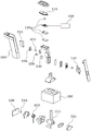
Fig. 1 is a perspective view exemplarily showing a stick type integrated control unit of a vehicle according to an exemplary embodiment of the present invention;
fig. 2 is a configuration diagram showing a stick type integrated control unit of a vehicle according to an exemplary embodiment of the present invention;
fig. 3 is a diagram showing an acceleration unit and an acceleration controller of a stick type integrated control unit of a vehicle according to an exemplary embodiment of the present invention;
fig. 4 is a diagram illustrating a driving principle of an acceleration unit of a stick type integrated control unit of a vehicle according to an exemplary embodiment of the present invention;
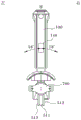
fig. 5 is a diagram illustrating a steering unit of a stick type integrated control unit of a vehicle according to an exemplary embodiment of the present invention;
fig. 6A and 6B are diagrams illustrating a driving principle of a steering unit of a stick type integrated control unit of a vehicle according to an exemplary embodiment of the present invention;
fig. 7 is a diagram illustrating a steering function driving state of a steering unit of a stick type integrated control unit of a vehicle according to an exemplary embodiment of the present invention.
It is to be understood that the drawings are not necessarily to scale, presenting a simplified representation of various illustrative features illustrative of the basic principles of the invention. The specific design features included in the present invention, including, for example, specific dimensions, orientations, locations, and shapes, will be determined in part by the particular intended application and environment of use.
In the drawings, like reference characters designate identical or equivalent parts throughout the several views.
Detailed Description
Reference will now be made in detail to various embodiments of the invention, examples of which are illustrated in the accompanying drawings and described below. While the invention will be described in conjunction with the exemplary embodiments of the invention, it will be understood that the description is not intended to limit the invention to those exemplary embodiments. On the other hand, the present invention is intended to cover not only exemplary embodiments of the present invention, but also various alternatives, modifications, equivalents and other embodiments, which may be included within the spirit and scope of the present invention as defined by the appended claims.
Embodiments of the present invention will be described in detail below with reference to the accompanying drawings. The exemplary embodiments of the present invention may be modified in various forms, and the scope of the present invention may not be construed as being limited to the following embodiments. These embodiments are provided so that this disclosure will be thorough and complete to those skilled in the art.
The terms "portion", "unit", and the like as used herein refer to a unit that handles at least one function or operation, and the unit may be implemented by hardware, software, or a combination of hardware and software.
Further, in the exemplary embodiment, the "width direction" and the "length direction" are vehicle-based.
Further, in exemplary embodiments, when a portion is referred to as being "on" or "over" another portion, this includes not only the case where the portion is "directly over" the other portion, but also the case where the other portion exists between the portion and the other portion. Further, in the exemplary embodiments, when a part is referred to as being "under" or "beneath" another part, this includes not only a case where the part is "directly under" the another part, but also a case where the another part exists between the part and the another part.
Further, in the exemplary embodiment, "clockwise" and "counterclockwise" are based on the drawings.
Fig. 1 is a perspective view exemplarily showing a stick type integrated control unit of a vehicle according to an exemplary embodiment of the present invention, and fig. 2 is a configuration diagram showing the stick type integrated control unit of the vehicle according to an exemplary embodiment of the present invention.
Referring to fig. 1 and 2, a lever type integrated control unit of a vehicle according to an exemplary embodiment of the present invention includes a lever housing 100, an acceleration unit 200, and an acceleration controller 300, the lever housing 100 being moved in a width direction of the vehicle by a driver's operation; the acceleration unit 200 is located at one end portion of the lever housing 100, and is configured to transmit acceleration information about the vehicle; the acceleration controller 300 is connected to the acceleration unit 200, and is configured to receive acceleration information about the vehicle from the acceleration unit 200.
Further, the lever-type integrated control unit of the vehicle further includes a hinge housing 400, a steering unit 500, and a steering controller 600, the hinge housing 400 being engaged with a lower end portion of the lever housing 100 and configured to fix the lever housing 100; the steering unit 500 is located at a lower end portion of the hinge housing 400, and is configured to move in response to displacement of the lever housing 100 and transmit steering information about the vehicle; the steering controller 600 is connected to the steering unit 500, and is configured to receive steering information about the vehicle from the steering unit 500.
The lever housing 100 may be configured to move in the width direction of the vehicle by the operation of the driver. The lever housing 100 may include an outer cover that contacts the driver's hand and an inner housing that engages various components that control the driving of the vehicle.
The acceleration unit 200 may be located at one end portion of the lever housing 100 and configured to transmit acceleration information related to the vehicle. The acceleration unit 200 may include an acceleration switch 210, a slider 220, an acceleration magnet 230, and an acceleration sensor 240.
The acceleration switch 210 may be located at one end portion of the lever housing 100 and selectively rotated and inserted into the lever housing 100. One end portion of the acceleration switch 210 may be hinged to one end portion of the lever housing 100 in the form of a trigger, and the other end portion thereof may be rotated and inserted into the lever housing 100. The acceleration unit 200 may be configured to perform acceleration control of the vehicle while the other end portion of the acceleration switch 210 is pressed by the operation of the driver.
The slider 220 may be installed to contact one end portion of the acceleration switch 210 and configured to be linearly moved in response to the movement of the acceleration switch 210. In response to the rotation of the acceleration switch 210, the slider 220 may move forward and backward in the longitudinal direction.
The accelerating magnet 230 may be fixed to the slider 220, and may be configured to linearly move integrally with the slider 220. The accelerating magnet 230 may be fixedly coupled to one end portion of the slider 220, and configured to move integrally with the slider 220 in a longitudinal direction of the slider 220.
The acceleration sensor 240 may be configured to be fixed to one end portion of the lever housing 100 by being spaced apart from the acceleration magnet 230 by a predetermined distance. The acceleration sensor 240 configured to detect a magnetic force may be mounted on a circuit board spaced apart from the acceleration magnet 230 by a predetermined distance. The acceleration sensor 240 may be a hall sensor using a magnet.
The acceleration sensor 240 may convert the magnetic force into an electrical signal. The acceleration sensor 240 may be configured to measure the position of the acceleration magnet 230 using an electrical signal (primarily a voltage detected by the acceleration sensor 240).
The acceleration controller 300 may be connected to the acceleration unit 200, and configured to receive acceleration information related to the vehicle from the acceleration unit 200. The acceleration controller 300 may be connected to the acceleration sensor 240 and configured to receive information from the acceleration sensor 240, the acceleration sensor 240 detecting an amount of linear movement of the acceleration magnet 230.
The acceleration controller 300 may be configured to control acceleration of the vehicle by adjusting engine Revolutions Per Minute (RPM), opening of a throttle valve, and the like, based on the received information and in communication with an engine controller of the vehicle.
The hinge housing 400 may be engaged with a lower end portion of the lever housing 100 and configured to fix the lever housing 100. The hinge housing 400 may be configured such that the upper end portion of the lever housing 100 may be moved in the width direction while the lower end portion of the lever housing 100 is fixed to the hinge housing 400.
The steering unit 500 may be located at a lower end portion of the hinge housing 400 and configured to move in response to displacement of the lever housing 100. Further, the steering unit 500 may be configured to transmit steering information related to the vehicle.
The steering controller 600 may be connected to the steering unit 500 and configured to receive steering information related to the vehicle from the steering unit 500. The steering controller 600 may be connected to the steering sensor 530 and configured to receive information from the steering sensor 530, and the steering sensor 530 detects the amount of rotation of the steering magnet 520.
The lever-type integrated control unit of the vehicle according to the exemplary embodiment of the present invention may further include a deceleration button 110, a deceleration unit 120, and a deceleration controller 130, the deceleration button 110 being located at an upper end portion of the lever housing 100; the deceleration unit 120 is located at one end portion of the deceleration button 110, and is configured to transmit deceleration information about the vehicle; the deceleration controller 130 is connected to the deceleration unit 120, and is configured to receive deceleration information about the vehicle from the deceleration unit 120.
In addition, the lever type integrated control unit of the vehicle may further include a shift button 140 located at one side surface of the lever housing 100, and may be configured to control shifting of the vehicle in response to a pressing input whether or not there is a shift button 140.
The deceleration button 110 may be disposed to be exposed at an upper end portion of the lever housing 100. The speed reduction button 110 may include a tact switch. When the driver presses the deceleration button 110, the deceleration button 110 may be configured to perform deceleration control of the vehicle even when the driver does not separately press the brake.
The deceleration unit 120 may be located at one end portion of the deceleration button 110 and configured to transmit deceleration information related to the vehicle. The deceleration unit 120 may include a pressure sensor and a printed circuit board, and measures pressure with which the driver presses the deceleration button 110.
The deceleration controller 130 may be connected to the deceleration unit 120 and configured to receive deceleration information related to the vehicle from the deceleration unit 120. When the deceleration unit 120 measures the pressure value and transmits the measured pressure value, the deceleration controller 130 may be configured to receive the information and control the deceleration amount of the vehicle.
In the case of a hybrid vehicle, the deceleration may be performed by an electric motor, a friction brake, an engine RPM, or the like, and in the case of an internal combustion engine vehicle, the deceleration may be performed by an engine RPM, a friction brake, or the like.
The shift button 140 may be located at one side surface of the lever housing 100. The lever-type integrated control unit of the vehicle may be configured to switch the traveling direction of the vehicle in response to a depression input of the shift button 140 by the driver. When the shift button 140 is pressed with the vehicle running forward, the lever-type integrated control unit of the vehicle may be configured to drive the vehicle in the backward direction of the vehicle, and when the shift button 140 is pressed again, the lever-type integrated control unit of the vehicle may be configured to switch the running direction of the vehicle from the backward direction thereof to the forward direction.
Fig. 3 is a diagram illustrating an acceleration unit 200 and an acceleration controller 300 of a stick type integrated control unit of a vehicle according to an exemplary embodiment of the present invention.
Referring to fig. 3, the lever-type integrated control unit of the vehicle according to an exemplary embodiment of the present invention may further include a return spring 250, which is located at an end portion of the slider 220. Further, the acceleration switch 210 may be configured such that one end portion thereof is hinged to one end portion of the lever housing 100 such that the other end portion thereof is inserted into the lever housing 100, and the return spring 250 may be configured to apply an elastic force such that the other end portion of the acceleration switch 210 is restored to a position.
The return spring 250 may be fixed to an end portion of the slider 220. The return spring 250 may be located between one end portion of the slider 220 and the inner housing of the lever housing 100, and configured to restore the position of the acceleration switch 210 by the slider 220. When the other end portion of the acceleration switch 210 is inserted into the lever housing 100 based on the hinge coupling of the one end portion of the acceleration switch 210, the return spring 250 may be configured to apply an elastic force to the other end portion of the acceleration switch 210 to restore its position.
When the acceleration switch 210 is pressed to perform a rotational motion and the slider 220 performs a linear motion by interlocking with the rotational motion, the return spring 250 may be compressed in a longitudinal direction thereof. When the driver does not press the acceleration switch 210, the return spring 250 is extended again, the slider 220 moves in the longitudinal direction thereof, and the acceleration switch 210 may be configured to perform rotation by interlocking with the movement of the slider 220.
Fig. 4 is a diagram illustrating a driving principle of an acceleration unit 200 of a stick type integrated control unit of a vehicle according to an exemplary embodiment of the present invention.
Referring to fig. 4, the acceleration sensor 240 may be configured to measure the amount of linear movement of the acceleration magnet 230, transmit information about the amount of linear movement to the acceleration controller 300, and drive the acceleration of the vehicle.
The acceleration sensor 240 may be located at a predetermined distance from the acceleration magnet 230, and may measure a linear movement amount of the acceleration magnet 230. When the acceleration magnet 230 linearly moves, a magnetic force may be generated, and the acceleration sensor 240 may convert the magnetic force into an electrical signal. The acceleration sensor 240 may be configured to detect a voltage to measure the amount of movement of the acceleration magnet 230.
The acceleration sensor 240 measuring the movement amount of the acceleration magnet 230 may transmit information to the acceleration controller 300. The acceleration controller 300 connected to the acceleration sensor 240 may be configured to receive information of the movement amount of the acceleration magnet 230, so that accelerated running of the vehicle may be driven.
Fig. 5 is a diagram illustrating a steering unit 500 of a stick type integrated control unit of a vehicle according to an exemplary embodiment of the present invention, and fig. 6A and 6B are diagrams illustrating a driving principle of the steering unit 500 of the stick type integrated control unit of the vehicle according to an exemplary embodiment of the present invention.
Referring to fig. 5, 6A and 6B, a steering unit 500 of a rod-type integrated control unit of a vehicle according to an exemplary embodiment of the present invention may include a rod hinge portion 510, a steering magnet 520, and a steering sensor 530.
The lever hinge portion 510 may be configured to pivot in response to movement of the lever housing 100. The lever hinge portion 510 may include a lever hinge 511, the lever hinge 511 being fixed in the hinge housing 400 and configured to pass through the inside of the lever housing 100 to be interlocked with the movement of the lever housing 100, and a torsion spring 512 configured to contact the lever hinge 511.
The lever hinge 511 is inserted through the lever housing 100, and when the driver moves the lever housing 100 in the width direction of the lever housing 100, the lever hinge 511 may pivot integrally with the lever housing 100.
The torsion spring 512 may be configured to contact the lever hinge 511. A protrusion may be formed at one end portion in the longitudinal direction of the lever hinge 511. The torsion spring 512 is positioned coaxially with the lever hinge 511 such that the protruding portion of the lever hinge 511 can be caught by one end portion of the torsion spring 512, thereby applying an elastic force to restore the lever hinge 511.
The torsion spring 512 may be formed on each of the front and rear surfaces of the lever hinge 511. For example, when the lever hinge 511 is pivoted in a clockwise direction thereof, the torsion spring 512 mounted on one surface of the lever hinge 511 may exert an elastic force by being pivoted again in a counterclockwise direction thereof to restore the lever hinge 511. In contrast, when the lever hinge 511 is pivoted in the counterclockwise direction thereof, the torsion spring 512 mounted on the other surface of the lever hinge 511 may exert an elastic force by being pivoted in the clockwise direction thereof again to restore the lever hinge 511.
The steering magnet 520 may be fixed to a central shaft of the rod hinge portion 510 or the rod hinge portion 510, and configured to pivot integrally with the rod hinge portion 510. The steering sensor 530 may be fixed in the hinge housing 400 by being spaced apart from the steering magnet 520 by a predetermined distance. Further, the steering sensor 530 may be configured to measure the amount of rotation of the steering magnet 520, transmit information of the amount of rotation to the steering controller 600, and drive the steering of the vehicle.
The steering sensor 530 may be configured to be spaced apart from the steering magnet 520 by a predetermined distance. The steering sensor 530 configured to detect a magnetic force may be disposed on a circuit board spaced apart from the steering magnet 520 by a predetermined distance. The steering sensor 530 may be a hall sensor using a magnet.
The steering sensor 530 may convert the magnetic force into an electrical signal. The steering sensor 530 may be configured to measure the position of the steering magnet 520 using an electrical signal (primarily a voltage detected by the steering sensor 530).
The steering sensor 530 may be located at a predetermined distance from the steering magnet 520, and may measure the amount of rotation of the steering magnet 520. A magnetic force may be generated when the steering magnet 520 is rotationally moved, and the steering sensor 530 may convert the magnetic force into an electrical signal. The steering sensor 530 may be configured to detect a voltage to measure the amount of rotation of the steering magnet 520.
The steering sensor 530, which measures the amount of rotation of the steering magnet 520, may transmit information to the steering controller 600. The steering controller 600 connected to the steering sensor 530 may be configured to receive information on the amount of rotation of the steering magnet 520, so that the steering of the vehicle may be driven.
Fig. 7 is a diagram illustrating a steering function driving state of a steering unit of a stick type integrated control unit of a vehicle according to an exemplary embodiment of the present invention.
Referring to fig. 7, a lever hinge 511 of a lever-type integrated control unit of a vehicle according to an exemplary embodiment of the present invention may pivot and move at a predetermined angle, and a torsion spring 512 may be configured to apply an elastic force to restore the lever hinge 511. In addition, the rod-type integrated control unit of the vehicle may further include a damper 700, the damper 700 being located in the hinge housing 400 by being adjacent to the steering unit 500 and configured to generate a reaction force against pivoting of the steering unit 500.
The lever hinge 511 is pivotally movable at a predetermined angle in the width direction of the vehicle. When the driver operates the lever housing 100 to move the lever hinge 511 in a clockwise direction thereof by a predetermined angle, the lever-type integrated control unit of the vehicle may be configured to steer the driving direction of the vehicle to the right side of the vehicle. In contrast, when the driver operates the lever housing 100 to move the lever hinge 511 at a predetermined angle in the counterclockwise direction thereof, the lever-type integrated control unit of the vehicle may be configured to steer the driving direction of the vehicle to the left side of the vehicle.
When the lever hinge 511 is pivotally moved in a clockwise direction thereof by a predetermined angle, the torsion spring 512 may be configured to apply an elastic force such that the lever hinge 511 is pivoted in a counterclockwise direction by a predetermined angle, thereby restoring the position of the lever hinge 511. Further, when the lever hinge 511 is pivotally moved at a predetermined angle in the counterclockwise direction thereof, the torsion spring 512 may be configured to apply an elastic force such that the lever hinge 511 is again pivoted at the predetermined angle in the clockwise direction, thereby restoring the position of the lever hinge 511.
The damper 700 may be located in the hinge housing 400 by being adjacent to the steering unit 500. The damper 700 may be configured to generate a reaction force against the rotation of the steering unit 500. The damper 700 may be connected to the hinge housing 400 and configured to prevent the lever hinge 511 from pivoting rapidly.
For example, the damper 700 may include a rotor having a cylindrical body (filled with silicon oil therein) and a rotational shaft having wings, and may be configured to generate rotation. When the rotor rotates, the silicone oil may form a resistance against the rotation of the rotor to generate a torque in a direction opposite to the rotation direction of the rotor. The damper 700 may be configured to limit rapid pivoting of the lever hinge 511 due to the opposing torque of the silicone oil. The damper 700 using a friction plate or electromagnetic force may be applied in addition to using a fluid such as silicon oil in the damper 700 of the present invention, and the present invention is not limited thereto.
The lever-type integrated control unit of the vehicle according to the exemplary embodiment of the present invention may be located in an interior appliance of the vehicle and configured to pop up or pop down using power generated from a driving portion of the vehicle.
The interior appliance of the vehicle may be an armrest of a seat. When the driver selects the pop-up function through a specific operation button associated with the pop-up function, the lever-type integrated control unit of the vehicle embedded in the armrest may pop up to be exposed to a usable state. Similarly, when the snap-in function is selected, the lever-type integrated control unit of the vehicle exposed to the armrest from the outside may be snapped downward to be embedded in the armrest.
The driving portion of the vehicle may be an actuator that provides driving force. The driving portion may transmit the driving force generated from the actuator to the lever-type integrated control unit of the vehicle such that the lever-type integrated control unit of the vehicle pops up or pops down.
In another exemplary embodiment of the present invention, the lever-type integrated control unit of the vehicle may be configured to automatically pop up for use when the vehicle is powered on, or to automatically pop down to remain in a storage state when the power of the vehicle is cut off. Here, the energization state may be a startup on state including an Accessory (ACC) or Ignition (IGN) on state.
Briefly, various aspects of the present invention provide a lever-type integrated control unit of a vehicle configured such that, by including an integrated system for steering control, acceleration control, brake control, and shift control in a single housing, the system can reduce individual components for driving, maximize the use of indoor space, and reduce the weight of the vehicle.
According to the above configuration, combination, and use relationship, the present invention can obtain the following effects.
By including an integrated system for steering control, acceleration control, brake control, and shift control in a single housing, there are effects of reducing individual components for driving, maximizing the use of indoor space, and reducing the weight of the vehicle.
Further, a stick type integrated control unit of a vehicle is provided, which is configured to control acceleration and steering driving only by operation of a button or only by direction adjustment of a stick by being connected to an acceleration unit, an acceleration controller, a steering unit, and a steering controller to be driven.
Further, the term "controller" refers to a hardware device that includes a memory and a processor configured to perform one or more steps (the steps are interpreted as an algorithmic structure). The memory stores algorithm steps, and the processor executes the algorithm steps to perform one or more programs of methods according to various exemplary embodiments of the present invention. The controller according to an exemplary embodiment of the present invention may be implemented by a nonvolatile memory configured to store an algorithm for controlling operations of various components of a vehicle or data on software commands for executing the algorithm and a processor; the processor is configured to perform the above-described operations using data stored in the memory. The memory and the processor may be separate chips. Alternatively, the memory and the processor may be integrated in a single chip. The processor may be implemented as one or more processors.
The controller may be at least one microprocessor operated by a predetermined program, which may include a series of commands for performing the methods according to various exemplary embodiments of the present invention.
The foregoing invention can also be embodied as computer readable codes in a computer readable recording medium. The computer readable recording medium is any data storage device that can store data which can be thereafter read by a computer system. Examples of the computer readable recording medium include a Hard Disk Drive (HDD), a Solid State Disk (SSD), a Silicon Disk Drive (SDD), a Read Only Memory (ROM), a Random Access Memory (RAM), a CD-ROM, a magnetic tape, a floppy disk, an optical data storage device, etc., and are implemented as a carrier wave (e.g., transmission through the Internet).
For convenience in explanation and accurate definition in the appended claims, the terms "upper", "lower", "inner", "outer", "upper", "lower", "upward", "downward", "front", "rear", "back", "inside", "outside", "inward", "outward", "inner", "outer", "forward" and "rearward" are used to describe features of the exemplary embodiments with reference to the positions of such features as displayed in the figures. It will be further understood that the term "connected," or derivatives thereof, refers to both direct and indirect connections.
Furthermore, the term "fixedly connected" means that the fixedly connected components always rotate at the same speed. Further, the term "selectively connectable" means "selectively connectable members will rotate individually when they are not engaged with each other, rotate at the same speed when they are engaged with each other, and are stationary when at least one of the selectively connectable members is a stationary member and the remaining selectively connectable members are engaged to the stationary member".
The foregoing descriptions of specific exemplary embodiments of the present invention have been presented for purposes of illustration and description. They are not intended to be exhaustive or to limit the invention to the precise embodiments disclosed, and obviously many modifications and variations are possible in light of the above teaching. The exemplary embodiments were chosen and described in order to explain certain principles of the invention and its practical application to enable others skilled in the art to make and use various exemplary embodiments of the invention and various alternatives and modifications thereof. It is intended that the scope of the invention be defined by the following claims and their equivalents.
The foregoing detailed description illustrates the invention. Moreover, the foregoing is intended to illustrate and describe exemplary embodiments of the invention, and the invention may be used in various other combinations, modifications, and environments. That is, substitutions or modifications may be made without departing from the scope, equivalents, or scope of the art to which exemplary embodiments of the invention relate. The described embodiments are intended to explain the best mode for carrying out the technical spirit of the invention and may be variously modified in specific applications and utilizations of the invention. Accordingly, the detailed description is not intended to limit the invention as in the exemplary embodiments included. Furthermore, it is intended that the appended claims be construed to include other exemplary embodiments of this invention.
Claims (13)
Applications Claiming Priority (2)
| Application Number | Priority Date | Filing Date | Title |
|---|---|---|---|
| KR1020200004787A KR20210091521A (en) | 2020-01-14 | 2020-01-14 | Lever Type Integrated Control Unit of Vehicle |
| KR10-2020-0004787 | 2020-01-14 |
Publications (1)
| Publication Number | Publication Date |
|---|---|
| CN113119724A true CN113119724A (en) | 2021-07-16 |
Family
ID=76763896
Family Applications (1)
| Application Number | Title | Priority Date | Filing Date |
|---|---|---|---|
| CN202010750805.3A Pending CN113119724A (en) | 2020-01-14 | 2020-07-30 | Rod type integrated control unit for vehicle |
Country Status (3)
| Country | Link |
|---|---|
| US (1) | US11235663B2 (en) |
| KR (1) | KR20210091521A (en) |
| CN (1) | CN113119724A (en) |
Cited By (3)
| Publication number | Priority date | Publication date | Assignee | Title |
|---|---|---|---|---|
| CN114407648A (en) * | 2022-02-18 | 2022-04-29 | 芜湖雄狮汽车科技有限公司 | Operating device, method and storage medium for accelerator and brake of automobile |
| CN114833849A (en) * | 2022-06-06 | 2022-08-02 | 深圳市尚为照明有限公司 | Explosion-proof robot |
| CN115705071A (en) * | 2021-08-09 | 2023-02-17 | 格拉默公司 | control device |
Families Citing this family (11)
| Publication number | Priority date | Publication date | Assignee | Title |
|---|---|---|---|---|
| US8978796B2 (en) * | 2012-01-06 | 2015-03-17 | Silvio Gallazzini | Tractor having dual hydrostatic drive with single hand control and attachment adapter for powered attachments |
| USD944816S1 (en) * | 2019-08-01 | 2022-03-01 | The Charles Machine Works, Inc. | Control lever |
| KR20220060594A (en) * | 2020-11-04 | 2022-05-12 | 현대자동차주식회사 | Integrated control apparatus for autonomous driving vehicle |
| EP4159587A1 (en) * | 2021-09-30 | 2023-04-05 | Grammer Ag | Device for vehicles for carrying out a steering movement |
| DE102021211284A1 (en) | 2021-10-07 | 2023-04-13 | Robert Bosch Gesellschaft mit beschränkter Haftung | Operating device for a motor vehicle |
| KR20240160879A (en) * | 2023-05-03 | 2024-11-12 | 현대자동차주식회사 | Integrated control apparatus for autonomous driving vehicle |
| JP7747426B2 (en) * | 2023-08-24 | 2025-10-01 | 三菱ロジスネクスト株式会社 | Forklift, lever resistance value change system and lever resistance value estimation program |
| JP7740858B2 (en) * | 2023-08-24 | 2025-09-17 | 三菱ロジスネクスト株式会社 | Forklifts, estimation systems and estimation programs |
| KR20250035889A (en) * | 2023-09-06 | 2025-03-13 | 현대자동차주식회사 | Steering and Driving Interface Device for Vehicles |
| USD1076835S1 (en) * | 2023-12-04 | 2025-05-27 | Dongguan Changsheng Technology Co., Ltd. | Control switch for car light |
| DE102024202992A1 (en) | 2024-03-28 | 2025-10-02 | Robert Bosch Gesellschaft mit beschränkter Haftung | Operating arrangement for a steer-by-wire steering system of a motor vehicle |
Citations (7)
| Publication number | Priority date | Publication date | Assignee | Title |
|---|---|---|---|---|
| CN1652961A (en) * | 2002-05-14 | 2005-08-10 | 丰田自动车株式会社 | vehicle controls |
| CN1968845A (en) * | 2004-06-14 | 2007-05-23 | 李昌学 | Joystick devices |
| CN102027458A (en) * | 2008-05-16 | 2011-04-20 | 通用汽车环球科技运作公司 | Method and apparatus for driver control of a limited-ability autonomous vehicle |
| CN103850285A (en) * | 2012-12-06 | 2014-06-11 | 迪尔公司 | Method and apparatus for ride control activation |
| CN105365571A (en) * | 2014-08-29 | 2016-03-02 | 现代自动车株式会社 | Lever for drive-by-wire system |
| CN106609529A (en) * | 2015-10-22 | 2017-05-03 | 迪尔公司 | Operator control for work vehicles |
| CN108506468A (en) * | 2017-02-24 | 2018-09-07 | 福特全球技术公司 | Mounted on the shift of transmission device with fold flat position of console |
Family Cites Families (9)
| Publication number | Priority date | Publication date | Assignee | Title |
|---|---|---|---|---|
| GB2295662A (en) * | 1994-11-28 | 1996-06-05 | Wah Leung Chan | Joystick eg for video games |
| DE19548717C1 (en) * | 1995-12-23 | 1997-05-07 | Daimler Benz Ag | Control element arrangement for controlling the longitudinal movement and / or the transverse movement of a motor vehicle |
| US6145401A (en) * | 1997-11-21 | 2000-11-14 | Caterpillar Inc. | Modular control handle |
| US6624806B2 (en) * | 2001-08-27 | 2003-09-23 | Weistech Technology Co., Ltd. | Joystick capable of controlling direction rudder and accelerator synchronously |
| DE10217039B3 (en) * | 2002-04-12 | 2004-02-26 | Fernsteuergeräte Kurt Oelsch GmbH | Control handle with operating units |
| KR20170066721A (en) | 2015-12-04 | 2017-06-15 | 현대자동차주식회사 | Shift lever assembly for automatic transmission vehicle |
| DE102015226321A1 (en) * | 2015-12-21 | 2017-06-22 | Zf Friedrichshafen Ag | Gear selector switch for a motor vehicle and method for detecting actuation of a gear selector switch for a motor vehicle |
| DE102017202437A1 (en) * | 2017-02-15 | 2018-08-16 | Zf Friedrichshafen Ag | Device and method for controlling a vehicle and vehicle |
| US20190368599A1 (en) * | 2018-06-04 | 2019-12-05 | Ford Global Technologies, Llc | Sports shift knob with push button transmission |
-
2020
- 2020-01-14 KR KR1020200004787A patent/KR20210091521A/en not_active Ceased
- 2020-07-09 US US16/925,163 patent/US11235663B2/en active Active
- 2020-07-30 CN CN202010750805.3A patent/CN113119724A/en active Pending
Patent Citations (7)
| Publication number | Priority date | Publication date | Assignee | Title |
|---|---|---|---|---|
| CN1652961A (en) * | 2002-05-14 | 2005-08-10 | 丰田自动车株式会社 | vehicle controls |
| CN1968845A (en) * | 2004-06-14 | 2007-05-23 | 李昌学 | Joystick devices |
| CN102027458A (en) * | 2008-05-16 | 2011-04-20 | 通用汽车环球科技运作公司 | Method and apparatus for driver control of a limited-ability autonomous vehicle |
| CN103850285A (en) * | 2012-12-06 | 2014-06-11 | 迪尔公司 | Method and apparatus for ride control activation |
| CN105365571A (en) * | 2014-08-29 | 2016-03-02 | 现代自动车株式会社 | Lever for drive-by-wire system |
| CN106609529A (en) * | 2015-10-22 | 2017-05-03 | 迪尔公司 | Operator control for work vehicles |
| CN108506468A (en) * | 2017-02-24 | 2018-09-07 | 福特全球技术公司 | Mounted on the shift of transmission device with fold flat position of console |
Cited By (4)
| Publication number | Priority date | Publication date | Assignee | Title |
|---|---|---|---|---|
| CN115705071A (en) * | 2021-08-09 | 2023-02-17 | 格拉默公司 | control device |
| CN114407648A (en) * | 2022-02-18 | 2022-04-29 | 芜湖雄狮汽车科技有限公司 | Operating device, method and storage medium for accelerator and brake of automobile |
| CN114833849A (en) * | 2022-06-06 | 2022-08-02 | 深圳市尚为照明有限公司 | Explosion-proof robot |
| CN114833849B (en) * | 2022-06-06 | 2024-01-16 | 深圳市尚为照明有限公司 | Explosion-proof robot |
Also Published As
| Publication number | Publication date |
|---|---|
| US11235663B2 (en) | 2022-02-01 |
| KR20210091521A (en) | 2021-07-22 |
| US20210213829A1 (en) | 2021-07-15 |
Similar Documents
| Publication | Publication Date | Title |
|---|---|---|
| CN113119724A (en) | Rod type integrated control unit for vehicle | |
| US11021058B1 (en) | Foldable accelerator pedal apparatus equipped with hysteresis module for vehicle | |
| US7404342B2 (en) | Accelerator pedal for motorized vehicle | |
| CN113511068A (en) | Foldable pedal unit for autonomous vehicles | |
| EP0491752B1 (en) | Accelerator pedal for electronic throttle actuation system | |
| US9079492B2 (en) | Accelerator pedal device | |
| US8042430B2 (en) | Accelerator pedal for a vehicle | |
| EP2301788B1 (en) | Accelerator pedal apparatus | |
| US4986238A (en) | Throttle control system | |
| EP2390752A1 (en) | Accelerator Pedal For A Vehicle | |
| US8650984B2 (en) | Electronic clutch pedal assembly having varying resistance | |
| CN102029908B (en) | Accelerator pedal apparatus | |
| US20180001763A1 (en) | Reaction Force Output Device | |
| EP3088263B1 (en) | Pedal control device, particularly for a motor-vehicle | |
| US11167784B2 (en) | Handle-type integrated control device for vehicles | |
| JP2000326754A (en) | Accelerator pedal device for automobile | |
| US11416020B2 (en) | Integrated driving control device | |
| CN113511254B (en) | Integrated control unit for vehicles with in-wheel systems | |
| JP2002276804A (en) | Shifting device | |
| EP1942390B1 (en) | Accelerator pedal for motorized vehicle | |
| JP2013142378A (en) | Drive force control device | |
| CN113353141A (en) | Steering wheel and vehicle of vehicle | |
| JPH11200900A (en) | Accelerator lever mechanism |
Legal Events
| Date | Code | Title | Description |
|---|---|---|---|
| PB01 | Publication | ||
| PB01 | Publication | ||
| SE01 | Entry into force of request for substantive examination | ||
| SE01 | Entry into force of request for substantive examination | ||
| WD01 | Invention patent application deemed withdrawn after publication |
Application publication date: 20210716 |
|
| WD01 | Invention patent application deemed withdrawn after publication |