CN112993712B - Manufacturing method of commutator copper shell, commutator copper shell and commutator - Google Patents
Manufacturing method of commutator copper shell, commutator copper shell and commutator Download PDFInfo
- Publication number
- CN112993712B CN112993712B CN202110205169.0A CN202110205169A CN112993712B CN 112993712 B CN112993712 B CN 112993712B CN 202110205169 A CN202110205169 A CN 202110205169A CN 112993712 B CN112993712 B CN 112993712B
- Authority
- CN
- China
- Prior art keywords
- outer side
- hook
- commutator
- inner hook
- copper shell
- Prior art date
- Legal status (The legal status is an assumption and is not a legal conclusion. Google has not performed a legal analysis and makes no representation as to the accuracy of the status listed.)
- Active
Links
- RYGMFSIKBFXOCR-UHFFFAOYSA-N Copper Chemical compound [Cu] RYGMFSIKBFXOCR-UHFFFAOYSA-N 0.000 title claims abstract description 161
- 229910052802 copper Inorganic materials 0.000 title claims abstract description 161
- 239000010949 copper Substances 0.000 title claims abstract description 161
- 238000004519 manufacturing process Methods 0.000 title claims abstract description 24
- 238000005452 bending Methods 0.000 claims abstract description 38
- 238000004080 punching Methods 0.000 claims abstract description 23
- 239000000463 material Substances 0.000 claims abstract description 18
- 238000003466 welding Methods 0.000 claims description 126
- OKTJSMMVPCPJKN-UHFFFAOYSA-N Carbon Chemical compound [C] OKTJSMMVPCPJKN-UHFFFAOYSA-N 0.000 claims description 70
- 229910002804 graphite Inorganic materials 0.000 claims description 64
- 239000010439 graphite Substances 0.000 claims description 64
- 238000000034 method Methods 0.000 claims description 31
- 229910000679 solder Inorganic materials 0.000 claims description 20
- 238000000465 moulding Methods 0.000 claims description 10
- 229920001342 Bakelite® Polymers 0.000 claims description 5
- 239000004637 bakelite Substances 0.000 claims description 5
- 239000011159 matrix material Substances 0.000 claims description 3
- 230000000903 blocking effect Effects 0.000 claims description 2
- 238000005516 engineering process Methods 0.000 abstract description 6
- 238000007514 turning Methods 0.000 description 8
- 229910052799 carbon Inorganic materials 0.000 description 6
- 238000000641 cold extrusion Methods 0.000 description 6
- 238000003754 machining Methods 0.000 description 6
- 238000010586 diagram Methods 0.000 description 5
- 239000004020 conductor Substances 0.000 description 4
- 238000005520 cutting process Methods 0.000 description 4
- 238000003801 milling Methods 0.000 description 4
- 230000005540 biological transmission Effects 0.000 description 3
- 238000009413 insulation Methods 0.000 description 3
- 239000002699 waste material Substances 0.000 description 3
- 238000004804 winding Methods 0.000 description 3
- 238000001746 injection moulding Methods 0.000 description 2
- 238000012986 modification Methods 0.000 description 2
- 230000004048 modification Effects 0.000 description 2
- 239000000243 solution Substances 0.000 description 2
- ATJFFYVFTNAWJD-UHFFFAOYSA-N Tin Chemical compound [Sn] ATJFFYVFTNAWJD-UHFFFAOYSA-N 0.000 description 1
- 230000009286 beneficial effect Effects 0.000 description 1
- 230000015572 biosynthetic process Effects 0.000 description 1
- 230000001680 brushing effect Effects 0.000 description 1
- 230000007547 defect Effects 0.000 description 1
- 230000002950 deficient Effects 0.000 description 1
- 230000002349 favourable effect Effects 0.000 description 1
- 230000004907 flux Effects 0.000 description 1
- 239000000155 melt Substances 0.000 description 1
- 238000005498 polishing Methods 0.000 description 1
- 238000003825 pressing Methods 0.000 description 1
- 238000007639 printing Methods 0.000 description 1
- 239000004576 sand Substances 0.000 description 1
- 238000007493 shaping process Methods 0.000 description 1
Images



Classifications
-
- H—ELECTRICITY
- H01—ELECTRIC ELEMENTS
- H01R—ELECTRICALLY-CONDUCTIVE CONNECTIONS; STRUCTURAL ASSOCIATIONS OF A PLURALITY OF MUTUALLY-INSULATED ELECTRICAL CONNECTING ELEMENTS; COUPLING DEVICES; CURRENT COLLECTORS
- H01R43/00—Apparatus or processes specially adapted for manufacturing, assembling, maintaining, or repairing of line connectors or current collectors or for joining electric conductors
- H01R43/06—Manufacture of commutators
-
- H—ELECTRICITY
- H01—ELECTRIC ELEMENTS
- H01R—ELECTRICALLY-CONDUCTIVE CONNECTIONS; STRUCTURAL ASSOCIATIONS OF A PLURALITY OF MUTUALLY-INSULATED ELECTRICAL CONNECTING ELEMENTS; COUPLING DEVICES; CURRENT COLLECTORS
- H01R39/00—Rotary current collectors, distributors or interrupters
- H01R39/02—Details for dynamo electric machines
- H01R39/04—Commutators
Landscapes
- Engineering & Computer Science (AREA)
- Manufacturing & Machinery (AREA)
- Motor Or Generator Current Collectors (AREA)
- Manufacture Of Motors, Generators (AREA)
Abstract
The invention discloses a manufacturing method of a commutator copper shell, the commutator copper shell and a commutator, wherein the manufacturing method of the commutator copper shell comprises the following steps: s1, feeding a copper strip; s2, punching and forming; s3, bending the inner hook; s4, bending the outer hook; s5, rounding; s6, grooving; s7, folding the inner side inner hook; and S8, splitting the outer circle side inner hook. Firstly, punching and forming a copper strip to obtain an outline blank required to be unfolded by a copper shell; and finally, grooving, folding the inner side inner hook and splitting the outer side inner hook on the circularly processed annular blank to obtain the commutator copper shell with the required shape. The manufacturing method of the commutator copper shell has high material utilization rate, can save 20-40% of copper material, has simple processing technology, can be completed in a set of continuous dies, and greatly reduces the processing cost.
Description
Technical Field
The invention relates to the technical field of commutators, in particular to a commutator copper shell, a commutator copper shell and a commutator.
Background
The commutator is used for changing the direction of current in the rotor coil, so that the rotor is subjected to torque in the same direction when rotating from one magnetic pole to the other magnetic pole, thereby generating continuous rotation.
At present, a commutator comprises a graphite disc, a copper shell and an insulating base body, wherein the graphite disc comprises a graphite disc with a plurality of fan-shaped grooves uniformly distributed along the circumferential direction on an end plane or a graphite disc with a plane end face; the conductor connecting piece is provided with a welding inner hook part used for being connected with the graphite plate and a welding outer hook part used for being connected with the external winding wire in a welding mode; the welding inner hook parts of the conductor connecting pieces are welded and fixed on the graphite plates in one-to-one correspondence through welding fluxes; the insulating base body is filled among the conductor connecting pieces and used for realizing insulation among the conductor connecting pieces and enabling the graphite plate, the copper shell and the insulating base body to form the integral commutator.
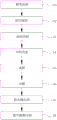
For example, chinese patent publication No. CN111916963A discloses a process for processing a copper shell of a commutator, the process flow diagram of which is roughly shown in fig. 1, and the process includes: step S1, cold extrusion: extruding the approximate shape of the copper shell; step S2, vehicle shape: the upper ring part and the lower ring part are obtained by turning the outer circle, so that a fall is formed between the upper ring part and the lower ring part; s3, punching an inner hook and a groove: punching an inner hook and various grooves of the copper shell; step S4, printing solder paste: brushing tin paste on the bottom end of the copper shell; s5, pasting and pressing top: the carbon sheet is contacted with one end of the copper shell piece, which is brushed with the solder paste, and the carbon sheet and the end of the copper shell piece are extruded to realize the removal of air between the carbon sheet and the solder paste and between the solder paste and the copper shell piece; step S6, welding: the carbon sheet and the copper shell piece are welded and fixed by vacuum welding; s7, turning the excircle of the lower ring part: cutting the excircle of the lower ring part to realize the coaxiality of the lower ring part and the carbon sheet; step S8, injection molding of the insulation body: injection molding the insulation body through a mold; s9, turning an inner hole, turning an outer circle, punching an inner hook, milling a hook and bending the hook: cutting off unnecessary parts through equipment, milling hooks through the equipment, and bending the milled hook parts to form hook bending parts; step S10, finishing: and sequentially performing sand polishing, tinning, carbon surface turning and groove milling on the commutator.
In the processing technology of the commutator copper shell, aiming at the processing part of the copper shell, the processed and cut part of the copper shell has more waste materials, the utilization rate of copper materials is lower, and the material cost of the product is increased; in the cold extrusion process, the requirement on the strength of the die is high, the service life of the die is short, and the cost of accessories is high; in cold extrusion, punching of the inner hook and the punching of the groove, turning of the excircle of the lower ring part, turning of the inner hole, turning of the excircle, punching of the inner hook, milling of the hook and bending and finish machining processes, the number of machining procedures is large, machining cost is high, and machining cost is increased.
Disclosure of Invention
Therefore, the invention aims to overcome the defects of low copper material utilization rate, multiple processing procedures and high production cost in the commutator copper shell processing technology in the prior art, and provides a commutator copper shell manufacturing method, a commutator copper shell and a commutator.
In order to solve the technical problems, the technical scheme of the invention is as follows:
a manufacturing method of a commutator copper shell comprises the following steps:
s1, feeding a copper strip;
s2, punching and forming: punching and forming a copper shell unfolding blank on a copper strip, wherein the copper strip comprises an outer side part, a plurality of welding inner hook parts which are connected to one side of the outer side part and are arranged at intervals and used for welding, and a plurality of wire hanging outer hook parts which are connected to the other side of the outer side part and are arranged at intervals and used for hanging wires of a commutator; the positions of the plurality of welding inner hook parts and the positions of the wire hanging outer hook parts are in one-to-one correspondence;
s3, bending an inner hook: bending the plurality of welding inner hook parts integrally to enable each welding inner hook part to be perpendicular to the outer side part;
s4, bending an outer hook: bending the plurality of wire hanging outer hook parts integrally to enable the wire hanging outer hook parts and the outer side parts to be perpendicular to each other;
s5, rounding: bending the outer side part into a circle along the thickness direction of the outer side part, wherein two ends of the outer side part are connected end to form a circular ring shape, the plurality of welding inner hook parts are enclosed on the inner side of the circular ring-shaped outer side part in the bending process, the wire hanging outer hook part extends outwards to form an outer hook part used for hanging wires on the outer side part, and the top surface of the wire hanging outer hook part is higher than the upper top surface of the outer side part;
s6, grooving: grooving the inner side wall of the circular outer side part between any two adjacent welding inner hook parts; the outer side part is grooved and then comprises a plurality of connecting sections with larger radial thickness and a plurality of bridging sections with smaller radial thickness, and the welding inner hook part and the wire hanging outer hook part are both connected to the annular outer side part;
s7, folding the inner side inner hook: bending one end of the welding inner hook part, which is far away from the outer side part, inwards to form an inner bent hook which extends in a direction oblique to the outer side part at the end part of the welding inner hook part, which is far away from the outer side part;
s8, splitting the outer circle side inner hook: and splitting the inner side wall of the connecting section into a slot, wherein the split part of the connecting section forms an inner split hook of the outer side part.
Further, in the step S1, the copper strip used in the copper material feeding process is a step-shaped copper strip with a thickness difference, and the step-shaped copper strip includes a first portion with a large thickness and a second portion with a small thickness; in the step S2, the first part is used for punching and molding the outer side portion and the plurality of outer hook portions of the hanging wire, and the second part is used for punching and molding the plurality of inner welded hook portions arranged at intervals.
Further, in the step S2, the first portion blanking and the second portion blanking are performed simultaneously in a single blanking process.
Further, the order of the S3 step and the S4 step may be interchanged.
Further, the order of the step S7 and the step S8 may be interchanged.
The commutator copper shell is manufactured by the manufacturing method of the commutator copper shell, and comprises an outer side part and a bottom part, wherein the outer side part forms the outer side wall of the commutator copper shell, the bottom part forms the bottom wall of the commutator copper shell, and the outer side part and the bottom part are integrally molded;
the bottom part comprises a plurality of welding inner hook parts which are circumferentially arranged at intervals, and the bottom surfaces of the welding inner hook parts are suitable for being connected with the graphite plate; the end part of the welding inner hook part, which is far away from the outer side part, is bent upwards to form an inner bent hook extending obliquely to the direction of the outer side part;
the outer side part is in a ring shape and comprises a connecting section of which the inner wall is connected with the welding inner hook part and a bridging section connected between two adjacent connecting sections; the thickness of the connecting section is larger than that of the bridging section in the radial direction of the commutator copper shell; the top of the connecting section is connected with a wire hanging outer hook part extending to the outer side of the outer side part; the top surface of the outer hook part of the hanging wire is higher than the upper top surface of the connecting section; and an inner split hook extending into the commutator copper shell is formed on the inner side wall of the connecting section.
Further, the welding inner hook part includes a tail end part connected with the outer side part and a tip end part connected with the tail end part; the width of the tip part is gradually reduced from one end close to the tail part to the other end far away from the tail part, and the width of one end of the tip part close to the tail part is larger than that of the tail part, so that grooves are formed on the tip part, the tail part and the inner wall of the outer side part; the end part of the tip part far away from the tail end part is bent upwards to form an inner hook extending obliquely towards the outer side part.
Further, the bridge section may be cut away to separate a plurality of the connection sections from each other.
Furthermore, in the circumferential direction of the commutator copper shell, the outer arc length of the bridging section is 1/3-3/5 of the outer arc length of the connecting section; the width of the narrowest part of the tail end part is 1/4-2/5 of the length of the outer circular arc of the connecting section.
A commutator, comprising:
the graphite plate is a plane graphite plate with a plurality of layers of steps on the outer circular surface, or a graphite plate with a plurality of fan-shaped grooves uniformly distributed along the circumferential direction on the plane;
the commutator copper shell adopts the commutator copper shell; a plurality of welding inner hook parts of the commutator copper shell are correspondingly welded on stepped end faces of the graphite discs or in the fan-shaped grooves one by one, and the excircle of the commutator copper shell is coaxial with the excircle of the graphite disc;
and the insulating matrix is filled between the graphite disc and the commutator copper shell and is used for insulating among a plurality of independent copper shell pieces formed after the bridge sections of the commutator copper shell are cut off, and the graphite disc and the plurality of independent copper shell pieces form an integral structure.
Furthermore, the end face of the welding inner hook part, which is used for being connected with the graphite plate, is a plane or a plane with a groove; the outer side of the end face, used for being connected with the welding inner hook part, of the graphite disc is a step face, and a gap is formed between the step face and the welding inner hook part; and bakelite is filled in the gap and used for preventing the solder on the connecting surface of the welding inner hook part and the graphite disc from flowing out after being melted.
Furthermore, the height of the step surface from the end surface of the welding inner hook part is 0.3-0.5 mm, and the width of the step surface along the radial direction is 0.6-2.5 mm.
Furthermore, the surface of the graphite plate connected with the welding inner hook part is a plane or is provided with a protrusion, the protrusion is arranged on the surface of the graphite plate in a surrounding mode to form a groove, the shape of the groove is matched with the shape of the welding inner hook part, and the protrusion is used for blocking the welding inner hook part and the solder on the connection surface of the graphite plate to flow into the reversing groove after being melted.
The technical scheme of the invention has the following advantages:
1. the invention provides a manufacturing method of a commutator copper shell, which comprises the steps of feeding a copper strip, punching and molding to obtain a blank with a shape required by the unfolding of the copper shell; and finally, grooving, folding the inner side inner hook and splitting the outer side inner hook on the circularly processed annular blank to obtain the commutator copper shell with the required shape. According to the manufacturing method of the commutator copper shell, the cut waste materials in the copper strip processing process are less, the material utilization rate is high, 20-40% of copper materials can be saved, and the material utilization rate is improved; and the processing technology is simple, can be finished in a set of continuous dies, and can greatly reduce the processing cost.
2. According to the manufacturing method of the commutator copper shell, the copper strip used in the copper material feeding process is the step-shaped copper strip with the thickness difference, the thickness of the first part with the large thickness of the step-shaped copper strip is matched with the thickness of the outer side part of the commutator copper shell, the thickness of the second part with the small thickness of the step-shaped copper strip is matched with the thickness of the bottom part of the commutator copper shell, on one hand, the part with the large thickness can meet the strength of the outer hook part of the hanging wire, and the part with the small thickness can meet the strength of the welding inner hook part welded with the graphite disc, on the other hand, the small part of the tail end part is beneficial to bending forming, and the welding inner hook part is not easy to crack.
3. According to the manufacturing method of the commutator copper shell, the punching forming of the first part and the punching forming of the second part of the step-shaped copper strip are simultaneously carried out in one-step blanking process, so that the processing steps can be reduced, and the processing efficiency is improved.
4. According to the commutator copper shell provided by the invention, the top surface of the outer hook part of the hanging wire on the outer side part is higher than the top surface of the connecting section, and a height difference exists between the top surface and the top surface, so that the connection of the adjacent outer hook parts of the hanging wire is reduced.
5. According to the commutator copper shell provided by the invention, the width of the tail end part of the welding inner hook part of the commutator copper shell is smaller, so that the tip part of the welding inner hook part, the tail end part and the inner wall of the outer side part can form grooves, the distance between the tail end parts of two adjacent welding inner hook parts is increased, solder below the welding inner hook parts cannot flow into a reversing groove between the two welding inner hook parts after being melted, when a winding wire is externally connected to a connecting section of the outer side part, even if heat is transferred to the welding inner hook parts through the connecting section, the solder below the welding inner hook parts is melted, and due to the arrangement of the grooves, the melted solder cannot enter the reversing groove, so that alternate short circuit of a graphite disc below the welding inner hook parts cannot be caused, further, the reversing function of a commutator cannot be lost, and the defective rate of the commutator can be reduced. In addition, after the grooves on the two sides of the inner welding hook part are formed, the tail end part of the inner welding hook part forms a neck part with a smaller width, when the connecting section is heated, the neck part with the smaller width is required to be transmitted to the inner welding hook part, and because the width of the neck part is small, the efficiency of transmitting heat is poor, so that the heat transmission can be reduced, and the rapid temperature rise of the inner welding hook part is avoided.
6. According to the commutator provided by the invention, the step surface is arranged on the graphite disc, a gap is formed between the step surface and the end surface of the welding inner hook part, bakelite can be filled in the gap, and solder below the welding inner hook part can be prevented from flowing out after being melted.
7. According to the commutator provided by the invention, the surface of the graphite plate, which is connected with the welding inner hook part, is provided with the bulge, the bulge surrounds the graphite plate surface to form the groove, the shape of the groove is matched with the shape of the welding inner hook part, and the periphery of the bulge surrounds the groove, so that solder on the connecting surface of the welding inner hook part and the graphite plate can be prevented from overflowing to the reversing groove after being melted, and the electric short circuit can be avoided.
Drawings
In order to more clearly illustrate the embodiments of the present invention or the technical solutions in the prior art, the drawings used in the description of the embodiments or the prior art will be briefly described below, and it is obvious that the drawings in the following description are some embodiments of the present invention, and other drawings can be obtained by those skilled in the art without creative efforts.
FIG. 1 is a simplified process flow diagram of a prior art commutator manufactured by a cold extrusion inner hook process;
fig. 2 is a process flow chart of a method for manufacturing a copper shell of a commutator according to an embodiment of the invention;
fig. 3 is a schematic structural diagram of a copper shell of a commutator according to an embodiment of the invention;
FIG. 4 is a schematic structural view of a stepped copper strip used in the copper material feeding process in the embodiment of the present invention;
FIG. 5 is a schematic structural view of the stepped copper strip of FIG. 4 after being punched and formed;
FIG. 6 is a schematic view of the blank of FIG. 5 after bending the inner hook;
FIG. 7 is a schematic view of the structure of the blank of FIG. 6 after bending the outer hook;
FIG. 8 is a schematic view of the blank of FIG. 7 after being rounded;
FIG. 9 is a schematic view of the blank of FIG. 8 after being nicked;
FIG. 10 is a schematic view of the blank of FIG. 9 after being folded over the inside inner hook;
FIG. 11 is a schematic view of the blank of FIG. 10 after being split into an outer circular side inner hook;
fig. 12 is a schematic structural diagram of a first graphite disc provided in an embodiment of the present invention;
fig. 13 is a schematic structural diagram of a second graphite disc provided in the embodiment of the present invention.
Description of reference numerals: 1. a commutator copper case; 2. an outer side portion; 21. a connecting section; 211. a wire-hanging outer hook part; 212. an inner split hook; 22. a bridging section; 3. welding the inner hook part; 31. a tail end portion; 32. a tip portion; 33. an inner hook; 4. a graphite plate; 41. a step surface; 42. and (4) protruding.
Detailed Description
The technical solutions of the present invention will be described clearly and completely with reference to the accompanying drawings, and it should be understood that the described embodiments are some, but not all embodiments of the present invention. All other embodiments, which can be derived by a person skilled in the art from the embodiments given herein without making any creative effort, shall fall within the protection scope of the present invention.
In the description of the present invention, it should be noted that the terms "center", "upper", "lower", "left", "right", "vertical", "horizontal", "inner", "outer", etc., indicate orientations or positional relationships based on the orientations or positional relationships shown in the drawings, and are only for convenience of description and simplicity of description, but do not indicate or imply that the device or element being referred to must have a particular orientation, be constructed and operated in a particular orientation, and thus, should not be construed as limiting the present invention. Furthermore, the terms "first," "second," and "third" are used for descriptive purposes only and are not to be construed as indicating or implying relative importance.
In the description of the present invention, it should be noted that, unless otherwise explicitly specified or limited, the terms "mounted," "connected," and "connected" are to be construed broadly and may be, for example, fixedly connected, detachably connected, or integrally connected; can be mechanically or electrically connected; they may be connected directly or indirectly through intervening media, or they may be interconnected between two elements. The specific meanings of the above terms in the present invention can be understood in specific cases to those skilled in the art.
In addition, the technical features involved in the different embodiments of the present invention described below may be combined with each other as long as they do not conflict with each other.
The manufacturing method of the commutator copper shell shown in fig. 2-11 specifically comprises the following steps:
s1, feeding a copper strip.
S2, punching and forming: punching and forming a copper shell unfolding blank on a copper strip, wherein the copper strip comprises an outer side part, a plurality of welding inner hook parts which are connected to one side of the outer side part and are arranged at intervals and used for welding, and a plurality of wire hanging outer hook parts which are connected to the other side of the outer side part and are arranged at intervals and used for hanging wires of a commutator; the positions of the plurality of welding inner hook parts and the positions of the hanging wire outer hook parts are in one-to-one correspondence.
Specifically, in the step S1, the copper strip used in the copper material feeding process is a step-shaped copper strip with a thickness difference, and the step-shaped copper strip includes a first part with a large thickness and a second part with a small thickness; in the step S2, the first part is used for die-cutting and molding the outer side part and the plurality of outer hook parts of the hanging wire, and the second part is used for die-cutting and molding the plurality of welded inner hook parts arranged at intervals. Specifically, the thickness of the first part with the large thickness of the step-shaped copper strip is matched with the thickness of the outer side part of the commutator copper shell, and the thickness of the second part with the small thickness of the step-shaped copper strip is matched with the thickness of the bottom part of the commutator copper shell. So set up, the part that thickness is big can satisfy the intensity of string line outer hook portion on the one hand, and the part that thickness is little can satisfy with the intensity of hook portion in the welding of graphite dish welded, and on the other hand, the little part of tail end is favorable to bending the shaping, and hook portion is difficult for the fracture in the welding.
S3, bending an inner hook: and integrally bending the plurality of welding inner hook parts to ensure that each welding inner hook part is perpendicular to the outer side part.
Specifically, the plurality of welded inner hook portions are bent to the vertical direction of the outer side portion at one time by the aid of the mold, and the outer side portion is integrally positioned and fixed in the bending process, so that the bending process is guaranteed to be smoothly performed.
S4, bending an outer hook: and integrally bending the plurality of wire hanging outer hook parts to enable the wire hanging outer hook parts and the outer side parts to be perpendicular to each other.
Specifically, the outer side portion is integrally fixed, the plurality of the hanging wire outer hook portions are bent outwards by 90 degrees at one time by adopting a mold, the bending direction of the hanging wire outer hook portions is opposite to that of the welding inner hook portions, and the positions of the bent hanging wire outer hook portions and the positions of the welding inner hook portions are in one-to-one correspondence and are arranged in parallel.
S5, rounding: the outer side portion is bent into a circle along the thickness direction of the outer side portion, the two ends of the outer side portion are connected end to form a circular ring shape, the inner welding hook portions are surrounded on the inner side of the outer side portion in the bending process, the outer hanging wire hook portions extend outwards to form the hanging portions of the outer side portion, and the top surface of the outer hanging wire hook portions is higher than the upper top surface of the outer side portion.
Specifically, the outer side part is bent step by adopting a rounding die, the outer side part is bent and then connected end to form a circular blank, and the size of a gap at the joint of the outer side part is ensured to be smaller than a preset value. And after the circular blank is formed, a plurality of welding inner hook parts are arranged on the inner side of the circular blank as the end surface bottom wall of the commutator shell, and are uniformly arranged at intervals in the circumferential direction around the axis where the circle center of the circular blank is located. The rounded outer wire hook part extends outwards to form the hook part of the outer side part, the outer wire hook part is positioned at the top of the outer side part and is higher than the upper top surface of the outer side part, a step structure is formed between the outer wire hook part and the top of the outer side part, the height difference is formed between the outer wire hook part and the top of the outer side part, and the connection of the adjacent outer wire hook parts is reduced.
S6, grooving: grooving the inner side wall of the circular outer side part between any two adjacent welding inner hook parts; the outer side portion is grooved and then comprises a plurality of connecting sections with large radial thickness and a plurality of bridging sections with small radial thickness, and the welding inner hook portion and the wire hanging outer hook portion are connected to the annular outer side portion.
S7, folding the inner side inner hook: and bending one end of the welding inner hook part, which is far away from the outer side part, inwards, so that the end part of the welding inner hook part, which is far away from the outer side part, forms an inner hook extending in a direction oblique to the outer side part.
S7, folding the inner side inner hook: and bending one end of the welding inner hook part, which is far away from the outer side part, inwards to form an inner hook extending in a direction oblique to the outer side part at the end part of the welding inner hook part, which is far away from the outer side part.
S8, splitting the outer circle side inner hook: and splitting the inner side wall of the connecting section into a slot, wherein the split part of the connecting section forms an inner split hook of the outer side part.
Specifically, the steps of punching forming, bending of the inner hook, bending of the outer hook, grooving, splitting of the outer inner hook, bending of the inner hook and the like are continuously processed in a set of continuous dies, and production efficiency and product quality are greatly improved.
The manufacturing method of the commutator copper shell comprises the steps of feeding, punching and molding a copper strip to obtain a blank with the shape comprising an outer side part, a plurality of welding inner hook parts and a plurality of wire hanging outer hook parts; then respectively bending a plurality of welding inner hook parts and a plurality of hanging wire outer hook parts, wherein the welding inner hook parts are perpendicular to the outer side parts, the plurality of welding inner hook parts are directly formed into the bottom of the end face of the commutator copper shell, then rounding is carried out on the bent blank, the blank is connected end to form a circular ring shape, the outer side parts form an annular main body structure of the commutator copper shell, and the plurality of hanging wire outer hook parts extend outwards to form the hanging hook parts on the outer side parts; and finally, grooving the rounded annular blank, folding the inner side inner hook and splitting the outer side inner hook to obtain the commutator copper shell with the required shape. In the process of processing the copper strip into the commutator copper shell, the copper strip has less cut waste, and compared with the commutator copper shell manufactured by the cold extrusion forming process in the prior art, the copper strip can save 20-40% of copper materials, and the material utilization rate is improved; secondly, the processing technology is simple, and the processing can be completed in a set of continuous dies, so that the processing cost can be greatly reduced.
In a preferred embodiment, in the step S2, the first part of the stepped copper strip and the second part of the stepped copper strip are simultaneously punched and formed in one blanking process, so that the number of processing steps can be reduced, and the processing efficiency can be improved.
In alternative embodiments, the order of the steps S3 and S4 may be interchanged; the order of the step S7 and the step S8 may be interchanged.
Example two
As shown in fig. 3, an embodiment of the present invention further provides a copper shell for a commutator, which is manufactured by the manufacturing method of the copper shell for a commutator in the first embodiment. The commutator copper case 1 includes an outer side portion 2 constituting an outer side wall of the commutator copper case 1 and a bottom portion constituting an end face wall of the commutator copper case 1, the outer side portion 2 and the bottom portion being integrally molded.
The bottom comprises eight welding inner hook parts 3 which are circumferentially arranged at intervals, and the bottom surfaces of the welding inner hook parts 3 are suitable for being connected with a graphite disc; the end of the welding inner hook 3 away from the outer side 2 is bent upwards to form an inner hook 33 extending obliquely to the outer side 2. The outer side part 2 is annular, and the outer side part 2 comprises a connecting section 21 of which the inner wall is connected with the welding inner hook part 3 and a bridging section 22 connected between two adjacent connecting sections 21; in the radial direction of the commutator copper shell 1, the thickness of the connecting section 21 is greater than that of the bridging section 22; a wire-hanging outer hook 211 extending to the outside of the outer part 2 is connected to the top of the connecting section 21; the top surface of the hook part is higher than the upper top surface of the connecting section 21; an inner split hook 212 extending into the commutator copper shell 1 is formed on the inner side wall of the connecting section 21.
In the present embodiment, the welding inner hook 3 includes a tail end portion 31 connected to the outer side 2 and a tip end portion 32 connected to the tail end portion 31; the width of the tip portion 32 is gradually reduced from one end close to the tail portion 31 to the other end far away from the tail portion 31, and the width of the tip portion 32 close to the tail portion 31 is larger than that of the tail portion 31, so that the tip portion 32, the tail portion 31 and the inner wall of the outer side portion 2 form a groove; the end of the tip portion 32 away from the end portion 31 is bent upward to form an inner hook 33 extending obliquely toward the outer side portion 2.
During use of the commutator housing, the bridge section 22 can be cut away to separate a plurality of said connecting sections 21 from each other. The outer side 2 is located end to end in the bridging section 22. Since the bridge segment 22 needs to be cut off during use, the gap of the part does not affect the performance of the commutator.
In the present embodiment, in the circumferential direction of the commutator copper shell 1, the outer arc length of the bridging section 22 is 1/3 to 3/5, preferably 1/2, of the outer arc length of the connecting section 21; the width of the narrowest part of the tail end part 31 is 1/4-2/5, preferably 1/3 of the length of the outer circular arc of the connecting section 21.
According to the commutator copper shell 1, the width of the tail end part 31 of the welding inner hook part 3 of the commutator copper shell 1 is small, grooves can be formed in the tip end part 32 of the welding inner hook part 3, the tail end part 31 and the inner wall of the outer side part 2, the distance between the tail end parts 31 of two adjacent welding inner hook parts 3 is increased, solder below the welding inner hook parts 3 cannot flow into a reversing groove between the two welding inner hook parts 3 after being melted, when a winding wire is externally connected to the connecting section 21 of the outer side part 2, even if heat is transmitted to the welding inner hook parts 3 through the connecting section 21, the solder below the welding inner hook parts 3 is melted, due to the arrangement of the grooves, the melted solder cannot enter the reversing groove, alternate short circuit of a graphite plate below the welding inner hook parts 3 cannot be caused, further, the reversing function of the commutator cannot be lost, and the commutator can be reduced. In addition, after the grooves on the two sides of the welding inner hook 3 are formed, the tail end 31 of the welding inner hook 3 forms a neck with a small width, when the connecting section 21 is heated, the neck with the small width is required to be transmitted to the welding inner hook 3, and because the neck has a small width and poor heat transmission efficiency, the heat transmission can be reduced, and the rapid temperature rise of the welding inner hook 3 is avoided.
EXAMPLE III
As shown in fig. 3, the commutator comprises a graphite disc 4, a commutator copper shell 1 and an insulating base body. The graphite discs 4 can be plane discs with steps on the outer circle side or comprise eight fan-shaped graphite sheets which are uniformly distributed along the circumferential direction, and any two adjacent graphite discs are insulated from each other due to the reversing grooves; a commutator copper case 1, which is the commutator copper case 1 in the second embodiment; eight welding inner hook parts 3 of the commutator copper shell 1 are correspondingly welded on the graphite plate one by one; and the insulating matrix is filled between the graphite disc 4 and the commutator copper shell 1, and is used for insulating among a plurality of independent copper shell pieces formed after the bridge section 22 of the commutator copper shell 1 is cut off, and enabling the graphite disc 4 and the plurality of independent copper shell pieces to form an integral structure.
As shown in fig. 12 and 13, in this embodiment, the end surface of the welding inner hook 3 for connecting with the graphite plate is a flat end surface or a flat end surface with a groove; the outer side of the end face of the graphite disc, which is used for being connected with the welding inner hook part 3, is provided with a step surface 41, and a gap is formed between the step surface 41 and the welding inner hook part 3; and bakelite is filled in the gap and used for preventing the solder on the connecting surface of the welding inner hook part 3 and the graphite disc from flowing out after being melted. Specifically, the height of the step surface 41 from the end surface of the welding inner hook part 3 is 0.3-0.5 mm, and the width of the step surface 41 in the radial direction is 0.6-2.5 mm. The graphite disc is provided with a step surface 41, a gap exists between the step surface 41 and the end surface of the welding inner hook part 3, bakelite can be filled in the gap, and solder below the welding inner hook part 3 can be prevented from flowing out after being melted.
In this embodiment, the graphite plate with the surface that hook portion 3 is connected in the welding is the flush end face or is equipped with protruding 42, protruding 42 is in graphite plate surface encloses to close and forms the recess, the shape of recess with hook portion 3's appearance phase-match in the welding, protruding 42 is used for blockking hook portion 3 in the welding with solder on the graphite plate connection face melts the back flow direction in the switching-over inslot. The surface that hook portion 3 meets in graphite plate and the welding is equipped with arch 42, and arch 42 encloses at graphite plate surface and closes the formation recess, and the shape of recess and the appearance phase-match of hook portion 3 in the welding, arch 42 encloses all around, can block in the welding solder on hook portion 3 and the graphite plate connection face melt back overflow not flow to switching-over groove department, avoid causing the electrical short circuit.
In summary, the method for manufacturing the copper shell of the heat exchanger provided by the embodiment of the invention has the following advantages:
1. the copper material has high utilization rate, and compared with the commutator copper shell manufactured by the cold extrusion forming process in the prior art, the copper material can be saved by 20-40 percent, and the material utilization rate is improved;
2. the processing technology is simple, can be completed in a set of continuous dies, and can greatly reduce the processing cost;
3. the finished blank has less finish machining procedures and the machining cost is reduced.
It should be understood that the above examples are only for clarity of illustration and are not intended to limit the embodiments. Other variations and modifications will be apparent to persons skilled in the art in light of the above description. And are neither required nor exhaustive of all embodiments. And obvious variations or modifications therefrom are within the scope of the invention.
Claims (12)
1. A manufacturing method of a commutator copper shell is characterized by comprising the following steps:
s1, feeding a copper strip; the copper strip used in the copper material feeding process is a step-shaped copper strip with thickness difference, and the step-shaped copper strip comprises a first part with large thickness and a second part with small thickness;
s2, punching and forming: punching and forming a copper shell unfolding blank on a copper strip, wherein the copper strip comprises an outer side part, a plurality of welding inner hook parts which are connected to one side of the outer side part and are arranged at intervals and used for welding, and a plurality of wire hanging outer hook parts which are connected to the other side of the outer side part and are arranged at intervals and used for hanging wires of a commutator; the positions of the plurality of welding inner hook parts and the positions of the wire hanging outer hook parts are in one-to-one correspondence; the first part is used for punching and molding the outer side part and the plurality of outer hook parts of the hanging wire, and the second part is used for punching and molding the plurality of welding inner hook parts which are arranged at intervals;
s3, bending an inner hook: bending the plurality of welding inner hook parts integrally to enable each welding inner hook part to be perpendicular to the outer side part;
s4, bending an outer hook: bending the plurality of wire hanging outer hook parts integrally to enable the wire hanging outer hook parts and the outer side parts to be perpendicular to each other;
s5, rounding: bending the outer side part into a circle along the thickness direction of the outer side part, wherein two ends of the outer side part are connected end to form a circular ring shape, the plurality of welding inner hook parts are enclosed on the inner side of the circular ring-shaped outer side part in the bending process, the wire hanging outer hook part extends outwards to form an outer hook part used for hanging wires on the outer side part, and the top surface of the wire hanging outer hook part is higher than the upper top surface of the outer side part;
s6, grooving: grooving the inner side wall of the circular outer side part between any two adjacent welding inner hook parts; the outer side portion is grooved and then comprises a plurality of connecting sections with larger radial thickness and a plurality of bridging sections with smaller radial thickness, and the welding inner hook portion and the wire hanging outer hook portion are connected to the connecting sections of the annular outer side portion;
s7, folding the inner side inner hook: bending one end of the welding inner hook part, which is far away from the outer side part, inwards to form an inner bent hook which extends in a direction oblique to the outer side part at the end part of the welding inner hook part, which is far away from the outer side part;
s8, splitting the outer circle side inner hook: and splitting the inner side wall of the connecting section into a slot, wherein the split part of the connecting section forms an inner split hook of the outer side part.
2. The method of manufacturing a commutator copper shell according to claim 1, wherein in the step S2, the die-cut molding of the first portion and the die-cut molding of the second portion are performed simultaneously in a one-time blanking process.
3. The method for manufacturing a commutator copper shell according to claim 1, wherein the order of the S3 step and the S4 step is interchangeable.
4. The method of manufacturing a commutator copper shell according to claim 1, wherein the order of the S7 step and the S8 step is interchangeable.
5. A commutator copper shell manufactured by the manufacturing method of the commutator copper shell according to any one of claims 1 to 4, characterized by comprising an outer side portion (2) constituting an outer side wall of the commutator copper shell (1) and a bottom portion constituting a bottom wall of the commutator copper shell (1), the outer side portion (2) and the bottom portion being integrally molded;
the bottom comprises a plurality of welding inner hook parts (3) which are circumferentially arranged at intervals, and the bottom surfaces of the welding inner hook parts (3) are suitable for being connected with a graphite disc; the end part of the welding inner hook part (3) far away from the outer side part (2) is bent upwards to form an inner bent hook (33) extending obliquely to the direction of the outer side part (2);
the outer side part (2) is annular, and the outer side part (2) comprises a connecting section (21) of which the inner wall is connected with the welding inner hook part (3) and a bridging section (22) connected between two adjacent connecting sections (21); the thickness of the connecting section (21) is greater than the thickness of the bridging section (22) in the radial direction of the commutator copper shell (1); the top of the connecting section (21) is connected with a wire hanging outer hook part (211) extending to the outer side of the outer side part (2); the top surface of the outer hook part (211) of the hanging wire is higher than the upper top surface of the connecting section (21); and an inner split hook (212) extending into the commutator copper shell (1) is formed on the inner side wall of the connecting section (21).
6. Commutator copper housing according to claim 5, characterized in that the welded inner hook section (3) comprises a tail section (31) connected to the outer side section (2) and a tip section (32) connected to the tail section (31); the width of the tip part (32) is gradually reduced from one end close to the tail part (31) to the other end far away from the tail part (31), and the width of the tip part (32) close to the tail part (31) is larger than that of the tail part (31), so that the tip part (32), the tail part (31) and the inner wall of the outer side part (2) form a groove; the end part of the tip part (32) far away from the tail end part (31) is bent upwards to form an inner bent hook (33) extending obliquely to the direction of the outer side part (2).
7. Commutator copper housing according to claim 5, characterized in that the bridge section (22) is cuttable to separate a plurality of the connection sections (21) from each other.
8. The commutator copper shell according to claim 6, wherein the outer circular arc length of the bridge section (22) is 1/3-3/5 of the outer circular arc length of the connecting section (21) in the circumferential direction of the commutator copper shell (1); the width of the narrowest part of the tail end part (31) is 1/4-2/5 of the length of the outer circular arc of the connecting section (21).
9. A commutator, comprising:
the graphite plate (4) is a plane graphite plate with a plurality of steps on the outer circular surface or a graphite sheet comprising a plurality of fan-shaped grooves which are uniformly distributed along the circumferential direction;
a commutator copper case (1) using the commutator copper case according to any one of claims 5 to 8; a plurality of welding inner hook parts (3) of the commutator copper shell (1) are correspondingly welded on stepped end faces of a plurality of graphite discs or in fan-shaped grooves one by one, and the excircle of the commutator copper shell (1) is coaxial with the excircle of the graphite disc (4);
and the insulating matrix is filled between the graphite disc (4) and the commutator copper shell (1) and is used for insulating among a plurality of independent copper shell parts formed after the bridge section (22) of the commutator copper shell (1) is cut off, and the graphite disc (4) and the plurality of independent copper shell parts form an integral structure.
10. A commutator according to claim 9, in which the end face of the welded inner hook (3) for connection with the graphite disc (4) is planar or grooved; the outer side of the end face, used for being connected with the welding inner hook part (3), of the graphite disc (4) is a step face (41), and a gap is formed between the step face (41) and the welding inner hook part (3); and bakelite is filled in the gap and used for preventing solder on the connecting surface of the welding inner hook part (3) and the graphite disc (4) from flowing out after being melted.
11. The commutator according to claim 10, wherein the height of the step surface (41) from the end surface of the welding inner hook (3) is 0.3 to 0.5mm, and the width of the step surface (41) in the radial direction is 0.6 to 2.5mm.
12. The commutator according to claim 10, wherein the surface of the graphite plate (4) connected with the welding inner hook part (3) is a plane or is provided with a protrusion (42), the protrusion (42) surrounds the graphite plate surface to form a groove, the shape of the groove is matched with the shape of the welding inner hook part (3), and the protrusion (42) is used for blocking solder on the connecting surface of the welding inner hook part (3) and the graphite plate (4) from flowing into the commutator groove after being melted.
Priority Applications (1)
| Application Number | Priority Date | Filing Date | Title |
|---|---|---|---|
| CN202110205169.0A CN112993712B (en) | 2021-02-23 | 2021-02-23 | Manufacturing method of commutator copper shell, commutator copper shell and commutator |
Applications Claiming Priority (1)
| Application Number | Priority Date | Filing Date | Title |
|---|---|---|---|
| CN202110205169.0A CN112993712B (en) | 2021-02-23 | 2021-02-23 | Manufacturing method of commutator copper shell, commutator copper shell and commutator |
Publications (2)
| Publication Number | Publication Date |
|---|---|
| CN112993712A CN112993712A (en) | 2021-06-18 |
| CN112993712B true CN112993712B (en) | 2023-02-28 |
Family
ID=76350016
Family Applications (1)
| Application Number | Title | Priority Date | Filing Date |
|---|---|---|---|
| CN202110205169.0A Active CN112993712B (en) | 2021-02-23 | 2021-02-23 | Manufacturing method of commutator copper shell, commutator copper shell and commutator |
Country Status (1)
| Country | Link |
|---|---|
| CN (1) | CN112993712B (en) |
Families Citing this family (1)
| Publication number | Priority date | Publication date | Assignee | Title |
|---|---|---|---|---|
| CN117620003A (en) * | 2023-12-21 | 2024-03-01 | 安徽龙磁精密器件有限公司 | A commutator copper shell progressive die processing mold |
Citations (3)
| Publication number | Priority date | Publication date | Assignee | Title |
|---|---|---|---|---|
| CN1399808A (en) * | 1999-11-26 | 2003-02-26 | 科莱克托公司 | Plane commutator, method for producing the same and conductor blank and carbon disk for using to produce the same |
| CN1985417A (en) * | 2004-07-16 | 2007-06-20 | 科莱克特集团公司 | Method for the production of a planar commutator and conductor blank for a planar commutator |
| CN205985693U (en) * | 2016-05-30 | 2017-02-22 | 深圳市凯中精密技术股份有限公司 | Copper shell and have its commutator |
-
2021
- 2021-02-23 CN CN202110205169.0A patent/CN112993712B/en active Active
Patent Citations (3)
| Publication number | Priority date | Publication date | Assignee | Title |
|---|---|---|---|---|
| CN1399808A (en) * | 1999-11-26 | 2003-02-26 | 科莱克托公司 | Plane commutator, method for producing the same and conductor blank and carbon disk for using to produce the same |
| CN1985417A (en) * | 2004-07-16 | 2007-06-20 | 科莱克特集团公司 | Method for the production of a planar commutator and conductor blank for a planar commutator |
| CN205985693U (en) * | 2016-05-30 | 2017-02-22 | 深圳市凯中精密技术股份有限公司 | Copper shell and have its commutator |
Also Published As
| Publication number | Publication date |
|---|---|
| CN112993712A (en) | 2021-06-18 |
Similar Documents
| Publication | Publication Date | Title |
|---|---|---|
| CN208014475U (en) | Common mode choke | |
| CN112993712B (en) | Manufacturing method of commutator copper shell, commutator copper shell and commutator | |
| EP3133676B1 (en) | Method of manufacturing an electrical connector | |
| CN101924315B (en) | Commutator and manufacturing method thereof | |
| CN112820950B (en) | Cylindrical lithium ion battery and manufacturing method thereof | |
| CN214254507U (en) | A cylindrical lithium-ion battery | |
| CN212626197U (en) | Novel combined insulating busbar structure | |
| CN209787005U (en) | Motor rotor | |
| EP4131657A1 (en) | Electric energy transmission aluminum part and machining process therefor | |
| JP2000349533A (en) | Helical antenna | |
| CN117525176B (en) | Battery piece, solar battery serial-parallel connection unit, assembly and manufacturing method of battery piece and solar battery serial-parallel connection unit | |
| CN116705500B (en) | Winding and line pressing structure of network filter | |
| CN218070502U (en) | Commutator copper shell and commutator thereof | |
| CN113068297B (en) | FFC structure, production method thereof and power battery connector | |
| CN214900810U (en) | L-shaped metal pin structure of network filter shell | |
| CN210380568U (en) | Servo motor concatenation winding side plastic frock | |
| JP2019140796A (en) | Split conductor for segment coil | |
| CN221380655U (en) | Stator assembly of double-hairpin conductor and flat wire motor | |
| CN117254620B (en) | Motor end windings, stator components, motors and vehicles | |
| JP2007028759A (en) | Centralized power distribution member for motor, method for manufacturing central power distribution member, bus bar, and method for manufacturing bus bar | |
| CN219163712U (en) | Electric connection assembly | |
| CN107453177B (en) | Copper shell, commutator with copper shell and manufacturing method of commutator | |
| CN223713696U (en) | Stator punching sheet, stator core and motor | |
| CN119542700B (en) | Pole and processing method thereof, top cover assembly, battery cell, battery and power utilization device | |
| CN217666059U (en) | Cable core wire looping tool |
Legal Events
| Date | Code | Title | Description |
|---|---|---|---|
| PB01 | Publication | ||
| PB01 | Publication | ||
| SE01 | Entry into force of request for substantive examination | ||
| SE01 | Entry into force of request for substantive examination | ||
| GR01 | Patent grant | ||
| GR01 | Patent grant |