CN112993600B - Convenient electric connection joint - Google Patents
Convenient electric connection joint Download PDFInfo
- Publication number
- CN112993600B CN112993600B CN202110438682.4A CN202110438682A CN112993600B CN 112993600 B CN112993600 B CN 112993600B CN 202110438682 A CN202110438682 A CN 202110438682A CN 112993600 B CN112993600 B CN 112993600B
- Authority
- CN
- China
- Prior art keywords
- guide
- groove
- plate
- cable
- hole
- Prior art date
- Legal status (The legal status is an assumption and is not a legal conclusion. Google has not performed a legal analysis and makes no representation as to the accuracy of the status listed.)
- Active
Links
- 210000004907 gland Anatomy 0.000 claims abstract description 15
- 239000004020 conductor Substances 0.000 claims abstract description 4
- 210000001503 joint Anatomy 0.000 claims description 4
- 238000009434 installation Methods 0.000 claims description 3
- 238000005096 rolling process Methods 0.000 description 5
- 230000005611 electricity Effects 0.000 description 2
- 238000005452 bending Methods 0.000 description 1
- 230000009286 beneficial effect Effects 0.000 description 1
- 239000011810 insulating material Substances 0.000 description 1
- 230000004048 modification Effects 0.000 description 1
- 238000012986 modification Methods 0.000 description 1
Images


Classifications
-
- H—ELECTRICITY
- H01—ELECTRIC ELEMENTS
- H01R—ELECTRICALLY-CONDUCTIVE CONNECTIONS; STRUCTURAL ASSOCIATIONS OF A PLURALITY OF MUTUALLY-INSULATED ELECTRICAL CONNECTING ELEMENTS; COUPLING DEVICES; CURRENT COLLECTORS
- H01R4/00—Electrically-conductive connections between two or more conductive members in direct contact, i.e. touching one another; Means for effecting or maintaining such contact; Electrically-conductive connections having two or more spaced connecting locations for conductors and using contact members penetrating insulation
- H01R4/24—Connections using contact members penetrating or cutting insulation or cable strands
- H01R4/2404—Connections using contact members penetrating or cutting insulation or cable strands the contact members having teeth, prongs, pins or needles penetrating the insulation
- H01R4/2406—Connections using contact members penetrating or cutting insulation or cable strands the contact members having teeth, prongs, pins or needles penetrating the insulation having needles or pins
-
- H—ELECTRICITY
- H01—ELECTRIC ELEMENTS
- H01R—ELECTRICALLY-CONDUCTIVE CONNECTIONS; STRUCTURAL ASSOCIATIONS OF A PLURALITY OF MUTUALLY-INSULATED ELECTRICAL CONNECTING ELEMENTS; COUPLING DEVICES; CURRENT COLLECTORS
- H01R11/00—Individual connecting elements providing two or more spaced connecting locations for conductive members which are, or may be, thereby interconnected, e.g. end pieces for wires or cables supported by the wire or cable and having means for facilitating electrical connection to some other wire, terminal, or conductive member, blocks of binding posts
- H01R11/11—End pieces or tapping pieces for wires, supported by the wire and for facilitating electrical connection to some other wire, terminal or conductive member
- H01R11/20—End pieces terminating in a needle point or analogous contact for penetrating insulation or cable strands
Landscapes
- Connections Arranged To Contact A Plurality Of Conductors (AREA)
Abstract
A convenient electric connection joint belongs to the technical field of switch cabinets and comprises a base plate, a gland, a spring, a guide part, a pressing part and a positioning part, wherein the gland is installed above a bottom plate of the base plate, the spring is installed between the gland and the base plate, the guide part is installed at the end part of the base plate, a group of pressing parts are respectively installed on the base plate and the guide part, and the positioning part is installed between the guide part and the base plate. The base plate comprises a bottom plate, a cable groove, a step hole, a guide plate, grid lugs, a positioning rod hole, a contact plate, a support and bolts, the cable groove is formed in the bottom plate, the guide plate is arranged at one end of the cable groove, a through hole corresponding to the cable groove is formed in the guide plate, a pressing portion is installed on the guide plate, the grid lugs are arranged on the outer side of the guide plate, the positioning rod hole is formed in the rear of the grid lugs, and a positioning portion is installed in the positioning rod hole. A contact piece is arranged in a cable groove and made of a conductive material, two ends of the contact piece are respectively provided with an upward tip, the cable is pressed tightly by a pressing cover, and the tips pierce an insulating layer of the cable and tightly press a wire core of the cable to form a conductive path.
Description
Technical Field
The invention belongs to the technical field of switch cabinets, and particularly relates to a convenient electric connection joint.
Background
There are multiple common equipment in power supply distribution field, the cubical switchboard is one of them comparatively common, various power supply distribution equipment including the cubical switchboard all relate to the electricity and connect the operation, present common electricity is connected nothing two kinds, one kind is directly to twine the end of a thread and use the insulating tape to insulate, another kind is to use binding post to connect, these two kinds of modes have common shortcoming, all need carry out the wire stripping operation to the cable, this has increased the complexity of operation undoubtedly, and still require operating personnel to be equipped with the wire stripping instrument usually, otherwise difficult completion.
Disclosure of Invention
The present invention provides a convenient electrical connector to solve the above problems in the background art.
The technical problem solved by the invention is realized by adopting the following technical scheme:
the utility model provides a convenient electric connection connects, includes base plate, gland, spring, guide part, compresses tightly portion and location portion, and the gland is installed in the bottom plate top of base plate, and the spring mounting is between gland and base plate, and the guide part is installed at the base plate tip, respectively installs a set of portion that compresses tightly on base plate and the guide part, installs location portion between guide part and the base plate.
The base plate includes the bottom plate, the cable groove, the step hole, the baffle, the grid auricle, the locating lever hole, the contact, support and bolt, the cable groove has on the bottom plate, the step hole is at the transversal arrangement of bottom plate, the one end in cable groove has the baffle, have the through-hole corresponding with the cable groove on the baffle, the installation compresses tightly the portion on the baffle, the portion compresses tightly the cable in the through-hole of baffle, the grid auricle has in the baffle outside, install the guide part on the grid auricle, the rear of grid auricle has the locating lever hole, the downthehole location portion of installing of locating lever. A contact piece is arranged in a cable groove and made of a conductive material, two ends of the contact piece are respectively provided with an upward tip, the cable is pressed tightly by a pressing cover, and the tips pierce an insulating layer of the cable and tightly press a wire core of the cable to form a conductive path. A support is arranged above the bottom plate, a downward bolt is arranged in the center of the support, and the pressing cover is pressed downwards by the bolt.
The gland comprises a cover plate, a groove and a guide rod, the groove is formed in the bottom of the cover plate and corresponds to the cable groove, the guide rod is arranged at the bottom of the cover plate and corresponds to the step hole, and the diameter of the lower portion of the step hole is consistent with the diameter of the guide rod, so that the guide rod can guide the movement of the guide rod. The spring is arranged on the upper half part of the stepped hole, namely the part with a large caliber, and the upper end of the spring is contacted with the lower surface of the cover plate. The guide part comprises a guide groove, a single lug and a tooth groove, the number of the guide part corresponds to that of the cable grooves, the guide groove of the guide part corresponds to the through hole in the guide plate, the single lug is arranged on the lower side of the guide groove and is in butt joint with the grid lug, and the tooth groove is formed in the periphery of the single lug. The pressing part consists of four elastic sheets, and the pressing parts are respectively arranged on the guide plate and the guide groove. Location portion includes locating lever, anti-roll groove and constant head tank, and location portion installs at the locating lever downthehole, and the rear side of locating lever has anti-roll groove, and the front side of locating lever has the constant head tank, and the constant head tank accomplishes the location of guide part with the tooth's socket cooperation.
Further, the number of the cable slots is determined according to needs and can be 1-6.
Further, the number of the stepped holes is 2-4.
The invention has the beneficial effects that:
the electric connection device is used for electric connection in the technical field of power supply and distribution, particularly for electric connection operation of a switch cabinet, the electric connection contact piece with the tip is arranged in the electric connection device, wire stripping operation of cables is not needed, the efficiency of electric connection work is greatly improved, the electric connection device is provided with two groups of pressing parts, the cables can be pressed, unnecessary pulling of the cables is prevented, one end of the electric connection device is provided with a guide part, guide can be provided for the cables according to the trend requirement of cable wiring, and the cables are prevented from being bent accidentally after being connected.
Drawings
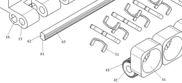
FIG. 1 is a schematic view of the present invention;
FIG. 2 is a left side view of the present invention;
FIG. 3 is an exploded view of the present invention;
FIG. 4 is a partial exploded view of the present invention;
in the figure: 10. the novel flat plate type cable end connector comprises a base plate, 11 parts of a bottom plate, 12 parts of a cable groove, 13 parts of a step hole, 14 parts of a guide plate, 15 parts of a grid lug, 16 parts of a positioning rod hole, 17 parts of a contact piece, 171 parts of a tip, 18 parts of a bracket, 19 parts of a bolt, 20 parts of a gland, 21 parts of a cover plate, 22 parts of a groove, 23 parts of a guide rod, 30 parts of a spring, 40 parts of a guide part, 41 parts of a guide groove, 42 parts of a single lug, 43 parts of a tooth groove, 50 parts of a pressing part, 51 parts of a spring sheet, 60 parts of a positioning part, 61 parts of a positioning rod, 62 parts of an anti-rolling groove and 63 parts of a positioning groove.
Detailed Description
To facilitate an understanding of the invention, the invention will now be described more fully with reference to the accompanying drawings. Preferred embodiments of the present invention are shown in the drawings. This invention may, however, be embodied in many different forms and should not be construed as limited to the embodiments set forth herein. Rather, these embodiments are provided so that this disclosure will be thorough and complete.
Referring to fig. 1-4, the convenient electrical connection joint includes a base plate 10, a pressing cover 20, a spring 30, a guide portion 40, a pressing portion 50 and a positioning portion 60, wherein the pressing cover 20 is mounted above a bottom plate 11 of the base plate 10, the spring 30 is mounted between the pressing cover 20 and the base plate 10, the guide portion 40 is mounted at an end portion of the base plate 10, a group of pressing portions 50 are respectively mounted on the base plate 10 and the guide portion 40, the positioning portion 60 is mounted between the guide portion 40 and the base plate 10, and the positioning portion 60 plays a role in positioning the guide portion 40.
The base plate 10 comprises a bottom plate 11, a cable groove 12, a step hole 13, a guide plate 14, a grid lug 15, a positioning rod hole 16, a contact piece 17, a bracket 18 and a bolt 19, wherein the cable groove 12 is arranged on the bottom plate 11, the number of the cable grooves 12 is determined according to requirements, the number of the stepped holes 13 is 1-6, the bottom plate 11 is provided with the stepped holes 13, the stepped holes 13 are transversely arranged on the bottom plate 11, the number of the stepped holes 13 is 2-4, the springs 30 are installed in the stepped holes 13, one end of the cable groove 12 is provided with the guide plate 14, the guide plate 14 is provided with through holes corresponding to the cable groove 12, the through holes are used for allowing cables to pass through, the pressing parts 50 are installed on the guide plate 14, the cables are pressed by the pressing parts 50 in the through holes of the guide plate 14, the outer side of the guide plate 14 is provided with the grid lug 15, the guide part 40 is installed on the grid lug 15, the positioning rod hole 16 is formed in the rear of the grid lug 15, the positioning part 60 is installed in the positioning rod hole 16, and the positioning part 60 plays a positioning role in positioning the guide part 40. The contact piece 17 is installed in the cable groove 12, the contact piece 17 is made of a conductive material, the contact piece 17 is used for conducting connection between two sections of cables which are in butt joint, two ends of the contact piece 17 are respectively provided with an upward tip 171, the cable is pressed by the pressing cover 20 to press the tip 171, the tip 171 punctures an insulating layer of the cable and compresses a wire core of the cable to form a conductive path, and of course, it should be added that other technical characteristics of the base plate 10 except the contact piece 17 are made of an insulating material. The upper part of the bottom plate 11 is provided with a bracket 18, a downward bolt 19 is arranged in the center of the bracket 18, and the bolt 19 presses the gland 20 downwards.
The gland 20 comprises a cover plate 21, a groove 22 and a guide rod 23, the groove 22 is formed in the bottom of the cover plate 21, the groove 22 corresponds to the cable groove 12, the guide rod 23 is formed in the bottom of the cover plate 21, the guide rod 23 corresponds to the stepped hole 13, the diameter of the lower portion of the stepped hole 13 is consistent with the diameter of the guide rod 23, and the guide rod 23 can guide movement of the guide rod 23. The spring 30 is installed on the upper half part of the stepped hole 13, namely, the part with a large caliber, the upper end of the spring 30 is in contact with the lower surface of the cover plate 21, under the action of the spring 30, when the bolt 19 is in a loose state, the gland 20 is always in an upper position, so that a cable can be conveniently threaded into the cable groove 12, and when the cable is threaded into the cable groove 12, the bolt 19 is tightened.
The guide part 40 comprises a guide groove 41, a single lug 42 and a tooth groove 43, the number of the guide part 40 corresponds to that of the cable grooves 12, the guide groove 41 of the guide part 40 corresponds to a through hole in the guide plate 14, the single lug 42 is arranged on the lower side of the guide groove 41, the single lug 42 is in butt joint with the grid lug 15, the guide part 40 can rotate on the grid lug 15, the guide part 40 is rotated according to the trend of the cable, the influence of the cable on the performance of the wire due to bending is avoided, the tooth groove 43 is arranged on the periphery of the single lug 42, and the tooth groove 43 is matched with the positioning groove 63 of the positioning part 60 for positioning.
The pressing part 50 is composed of four elastic sheets 51, the pressing parts 50 are mounted on the guide plate 14 and the guide groove 41 respectively, when the cable passes through the guide plate 14 and the guide groove 41, the pressing parts 50 utilize the four elastic sheets 51 to press the outer edge of the cable, free sliding of the cable is avoided, and only when the cable receives large external force to be pulled, the cable can slide in the pressing parts 50.
The positioning part 60 comprises a positioning rod 61, an anti-rolling groove 62 and a positioning groove 63, the positioning part 60 is installed in the positioning rod hole 16, the anti-rolling groove 62 is formed in the rear side of the positioning rod 61, the anti-rolling groove 62 is matched with a boss at a corresponding position in the positioning rod hole 16, the positioning rod 61 is prevented from rolling in the positioning rod hole 16, the positioning groove 63 is formed in the front side of the positioning rod 61, and the positioning groove 63 is matched with the tooth groove 43 to complete positioning of the guide part 40. After the guiding portion 40 rotates to a proper position, the positioning portion 60 is inserted, so that the guiding portion 40 can be positioned, and of course, the positioning portion 60 is inserted after all the guiding portions 40 are adjusted to the proper position.
The working principle of the invention is as follows: two segments of cables to be butted are inserted into the cable groove 12 from two ends of the cable groove 12, of course, the cables on one side of the guide part 40 should firstly pass through the guide groove 41, then pass through the guide plate 14, then pass through the cable groove 12, the bolt 19 is screwed, the gland 20 is pressed against the base plate 10, at this time, the two segments of cables are in conductive connection through the contact piece 17, and according to the field installation requirement, each guide part 40 is rotated to the required direction and inserted into the positioning part 60, and then the electric connection operation is completed. It should be noted that, of course, when inserting the positioning part 60, the guiding part 40 may need to be adjusted slightly to engage the tooth slots 43 and the positioning slots 63, but the fine adjustment does not affect the guiding function of the guiding part 40 for the cable running direction.
The above embodiments have mainly illustrated the convenient electrical connection terminal of the present invention. While only a limited number of embodiments and features have been described, those skilled in the art will recognize that the invention can be embodied in many other forms without departing from the spirit or scope thereof. The present embodiments are, therefore, to be considered in all respects as illustrative and not restrictive, and various modifications and alternative arrangements may be devised without departing from the spirit and scope of the present invention as defined by the appended claims.
Claims (3)
1. A convenient electric connection joint comprises a base plate (10), a gland (20), a spring (30), a guide part (40), a pressing part (50) and a positioning part (60), and is characterized in that the gland (20) is installed above a bottom plate (11) of the base plate (10), the spring (30) is installed between the gland (20) and the base plate (10), the guide part (40) is installed at the end part of the base plate (10), a group of pressing parts (50) are respectively installed on the base plate (10) and the guide part (40), the positioning part (60) is installed between the guide part (40) and the base plate (10), the base plate (10) comprises a bottom plate (11), a cable groove (12), a step hole (13), a guide plate (14), a grid lug (15), a positioning rod hole (16), a contact piece (17), a bracket (18) and a bolt (19), the cable groove (12) is arranged on the bottom plate (11), the step hole (13) is arranged on the bottom plate (11), the cable pressing cover comprises a bottom plate (11), step holes (13) are transversely arranged on the bottom plate (11), a guide plate (14) is arranged at one end of a cable groove (12), a through hole corresponding to the cable groove (12) is formed in the guide plate (14), a pressing part (50) is installed on the guide plate (14), cables are pressed in the through hole of the guide plate (14) by the pressing part (50), a grid lug (15) is arranged on the outer side of the guide plate (14), a guide part (40) is installed on the grid lug (15), a positioning rod hole (16) is formed in the rear of the grid lug (15), a contact piece (17) is installed in the cable groove (12), the contact piece (17) is made of a conductive material, an upward tip (171) is arranged at each end of the contact piece (17), a support (18) is arranged above the bottom plate (11), a downward bolt (19) is installed in the center of the support (18), the bolt (19) presses a pressing cover (20) downwards, and the pressing cover (20) comprises a cover plate (21), The cable guide plate comprises a groove (22) and a guide rod (23), the groove (22) is formed in the bottom of a cover plate (21), the groove (22) corresponds to a cable groove (12), the guide rod (23) is formed in the bottom of the cover plate (21), the guide rod (23) corresponds to a step hole (13), the caliber of the lower portion of the step hole (13) is consistent with the diameter of the guide rod (23), a spring (30) is installed on the upper half portion of the step hole (13), a guide portion (40) comprises a guide groove (41), a single lug (42) and a tooth groove (43), the number of the guide portion (40) corresponds to that of the cable groove (12), the guide groove (41) of the guide portion (40) corresponds to a through hole in a guide plate (14), the single lug (42) is arranged on the lower side of the guide groove (41), the single lug (42) is in butt joint with a grid lug (15), the periphery of the single lug (42) is provided with the tooth groove (43), and four elastic pieces (51) are respectively installed on each guide groove (41) and a pressing portion (50) of the through hole in the guide plate (14), each installation compresses tightly portion (50) on baffle (14) and guide way (41), location portion (60) are including locating lever (61), anti-roll groove (62) and constant head tank (63), location portion (60) are installed in locating lever hole (16), the rear side of locating lever (61) has anti-roll groove (62), boss that anti-roll groove (62) and corresponding position in locating lever hole (16) cooperate, prevent that locating lever (61) from taking place to roll in locating lever hole (16), the front side of locating lever (61) has constant head tank (63), the location of guide portion (40) is accomplished in constant head tank (63) and tooth's socket (43) cooperation.
2. The handy electrical connection joint as recited in claim 1, wherein the number of the cable grooves (12) is 1-6.
3. The handy electrical connection joint as recited in claim 1, wherein the number of the stepped holes (13) on the bottom plate (11) is 2-4.
Priority Applications (1)
| Application Number | Priority Date | Filing Date | Title |
|---|---|---|---|
| CN202110438682.4A CN112993600B (en) | 2021-04-23 | 2021-04-23 | Convenient electric connection joint |
Applications Claiming Priority (1)
| Application Number | Priority Date | Filing Date | Title |
|---|---|---|---|
| CN202110438682.4A CN112993600B (en) | 2021-04-23 | 2021-04-23 | Convenient electric connection joint |
Publications (2)
| Publication Number | Publication Date |
|---|---|
| CN112993600A CN112993600A (en) | 2021-06-18 |
| CN112993600B true CN112993600B (en) | 2021-07-23 |
Family
ID=76339909
Family Applications (1)
| Application Number | Title | Priority Date | Filing Date |
|---|---|---|---|
| CN202110438682.4A Active CN112993600B (en) | 2021-04-23 | 2021-04-23 | Convenient electric connection joint |
Country Status (1)
| Country | Link |
|---|---|
| CN (1) | CN112993600B (en) |
Citations (5)
| Publication number | Priority date | Publication date | Assignee | Title |
|---|---|---|---|---|
| JP2001035626A (en) * | 1999-07-21 | 2001-02-09 | Sumitomo Wiring Syst Ltd | Method for insulation displacement of wire with water- proof housing and its jig |
| CN1830118A (en) * | 2003-05-28 | 2006-09-06 | 科姆斯科普技术道具有限责任公司 | Back-end variation control cap for use with a jack module |
| CN101183756A (en) * | 2006-10-16 | 2008-05-21 | 日本航空电子工业株式会社 | Electrical connector with wire alignment and size reduction |
| CN106898886A (en) * | 2017-03-30 | 2017-06-27 | 宁波贝特贝尔通信设备有限公司 | Data cable connector |
| CN209709573U (en) * | 2019-03-20 | 2019-11-29 | 博信通信股份有限公司 | A kind of communication cabinet cable management device |
Family Cites Families (10)
| Publication number | Priority date | Publication date | Assignee | Title |
|---|---|---|---|---|
| CN85102325A (en) * | 1984-11-02 | 1986-04-10 | 克罗内有限公司 | The unit connector of insulated cable connection and the plastic clamping component that is attached thereto |
| JP2003163042A (en) * | 2001-11-27 | 2003-06-06 | Ozawa Tokushu Giken:Kk | Wire connecting appliance connecting wires without removing sheath thereof |
| US7261585B2 (en) * | 2005-03-07 | 2007-08-28 | Yazaki Corporation | Press-contact connector |
| CN101527401A (en) * | 2008-03-06 | 2009-09-09 | 贵州航天电器股份有限公司 | Connector accessory with stop teeth and adjustable outlet direction |
| CN103515724A (en) * | 2012-06-26 | 2014-01-15 | 张锐 | Communication wiring terminal |
| CN203733978U (en) * | 2013-08-18 | 2014-07-23 | 合肥市宏键精工模具有限责任公司 | Side cable-pressing high-temperature resistant alternating current cable connector |
| CN107681403A (en) * | 2017-10-20 | 2018-02-09 | 卞毓平 | A kind of collar style fixture to be continued for cable and its method of work |
| CN207518011U (en) * | 2017-12-15 | 2018-06-19 | 深圳市同心富精密电子有限公司 | High current socket connector |
| CN209544622U (en) * | 2019-03-20 | 2019-10-25 | 东莞品一自动化科技有限公司 | A piercing connector structure |
| CN111370900A (en) * | 2020-04-16 | 2020-07-03 | 公牛集团股份有限公司 | Socket with rotatable outlet wire |
-
2021
- 2021-04-23 CN CN202110438682.4A patent/CN112993600B/en active Active
Patent Citations (5)
| Publication number | Priority date | Publication date | Assignee | Title |
|---|---|---|---|---|
| JP2001035626A (en) * | 1999-07-21 | 2001-02-09 | Sumitomo Wiring Syst Ltd | Method for insulation displacement of wire with water- proof housing and its jig |
| CN1830118A (en) * | 2003-05-28 | 2006-09-06 | 科姆斯科普技术道具有限责任公司 | Back-end variation control cap for use with a jack module |
| CN101183756A (en) * | 2006-10-16 | 2008-05-21 | 日本航空电子工业株式会社 | Electrical connector with wire alignment and size reduction |
| CN106898886A (en) * | 2017-03-30 | 2017-06-27 | 宁波贝特贝尔通信设备有限公司 | Data cable connector |
| CN209709573U (en) * | 2019-03-20 | 2019-11-29 | 博信通信股份有限公司 | A kind of communication cabinet cable management device |
Also Published As
| Publication number | Publication date |
|---|---|
| CN112993600A (en) | 2021-06-18 |
Similar Documents
| Publication | Publication Date | Title |
|---|---|---|
| CN112993600B (en) | Convenient electric connection joint | |
| CN201112748Y (en) | Connector | |
| CN201608281U (en) | Special plug for busbar jack box | |
| CN107181101B (en) | Power distribution unit with hot plug socket | |
| CN201766303U (en) | Circuit allocation adaptor unit | |
| CN215418920U (en) | Connecting wire terminal crimping device | |
| CN216054384U (en) | Automatic reset wiring switch | |
| CN222321983U (en) | Server Cabinets | |
| CN108418024A (en) | Contact electrification connector is suppressed in separation | |
| CN219696720U (en) | Novel power electronic connector | |
| CN220021815U (en) | Line interference electricity treatment device | |
| CN220711021U (en) | Flat cable type electronic connecting wire | |
| CN223156288U (en) | Reliable binding post of electrical connection | |
| CN224138560U (en) | An electrical component mounting structure and a power distribution cabinet | |
| CN219017976U (en) | Combined connector convenient to install | |
| CN222168758U (en) | Linear light power terminal and line light | |
| CN214958080U (en) | Electric power electric appliance cabinet convenient to installation | |
| CN115313099B (en) | New energy battery connector | |
| CN222051674U (en) | A wiring terminal for a power distribution circuit breaker used in electrical engineering | |
| CN221176693U (en) | Power supply DC JACK high-current connector | |
| CN215869209U (en) | Conductive system device convenient to assemble | |
| CN223363490U (en) | Row inserts with sealed dustproof function | |
| CN219180445U (en) | Secondary plug-in terminal of low-voltage circuit breaker | |
| CN221379788U (en) | Terminal for connecting a plurality of terminals | |
| CN213936586U (en) | Low-cost single-ended binding post row |
Legal Events
| Date | Code | Title | Description |
|---|---|---|---|
| PB01 | Publication | ||
| PB01 | Publication | ||
| SE01 | Entry into force of request for substantive examination | ||
| SE01 | Entry into force of request for substantive examination | ||
| GR01 | Patent grant | ||
| GR01 | Patent grant |