Disclosure of Invention
In view of the above, the present invention provides a method, a device, a terminal and a computer readable storage medium for detecting wheel alignment imbalance, which are used to detect and determine the wheel alignment imbalance of a vehicle, so as to prompt a vehicle operator to maintain and correct the vehicle when the wheel alignment imbalance exists in the vehicle.
A first aspect of an embodiment of the present invention provides a method for detecting a wheel alignment misalignment, including:
acquiring sensor information in the running process of a vehicle, wherein the sensor information comprises a lateral acceleration measured value from a lateral accelerometer and a vehicle yaw rate from a yaw rate sensor;
acquiring the speed of the vehicle in the advancing direction;
calculating a lateral acceleration offset and a lateral acceleration adjustment value of the vehicle based on the lateral acceleration measurement, the vehicle yaw rate, and a vehicle speed of the vehicle in a forward direction;
judging whether the vehicle has wheel dislocation or not based on the lateral acceleration offset and the lateral acceleration adjustment value;
determining wheel-alignment-misalignment information of the vehicle based on a result of the determination and the lateral acceleration offset amount.
Optionally, the calculating a lateral acceleration offset and a lateral acceleration adjustment value of the vehicle based on the lateral acceleration measurement value, the vehicle yaw rate, and the vehicle speed of the vehicle in the forward direction includes:
calculating a lateral acceleration actual value of the vehicle based on the vehicle yaw rate and a vehicle speed of the vehicle in a forward direction;
calculating the difference between the actual value of the transverse acceleration and the measured value of the transverse acceleration to obtain the offset of the transverse acceleration;
a lateral acceleration adjustment value of the vehicle is calculated based on the lateral acceleration offset.
Optionally, the sensor information further includes a yaw rate measurement value from a yaw angle sensor, a steering angle value from a steering angle sensor;
the determining whether the vehicle has a wheel misalignment based on the lateral acceleration offset and the lateral acceleration adjustment value includes:
calculating a yaw rate calculation value of the vehicle;
calculating a lateral acceleration calculation value of the vehicle based on the yaw rate calculation value and the steering angle value;
if the measured value of the yaw angular velocity, the calculated value of the yaw angular velocity, the adjusted value of the lateral acceleration and the calculated value of the lateral acceleration meet a first preset condition, and the duration time meeting the first preset condition is longer than a first preset duration, determining that the vehicle has wheel dislocation;
wherein the first preset condition comprises: the absolute value of the measured value of the yaw rate is smaller than a preset first angular velocity threshold value, the absolute value of the difference between the calculated value of the yaw rate and the measured value of the yaw rate is larger than a preset second angular velocity threshold value, the absolute value of the adjusted value of the lateral acceleration is smaller than a preset first acceleration threshold value, the absolute value of the difference between the calculated value of the lateral acceleration and the adjusted value of the lateral acceleration is larger than a preset second acceleration threshold value, and the speed in the advancing direction of the vehicle is larger than a preset speed threshold value.
Optionally, the determining wheel alignment misalignment information of the vehicle based on the result of the determination and the lateral acceleration offset amount includes:
and if the vehicle has wheel misalignment and the lateral acceleration offset is smaller than an offset threshold value in a minimum time period, determining that the vehicle has potential wheel mispositioning.
Optionally, after the determining that the vehicle has the potential wheel alignment disorder, the method further includes:
determining the category corresponding to the potential wheel alignment maladjustment judged this time;
and evaluating the severity of the fault of the potential wheel alignment maladjustment determined at this time to obtain an evaluation value of the severity of the fault.
Optionally, before the determining the category corresponding to the potential wheel alignment misalignment determined this time, the method further includes:
calculating a first self-aligning torque representing the torque generated by coulomb friction and viscous friction generated by the power steering system during vehicle operation and a second self-aligning torque representing the lateral torque generated by the force acting on the vehicle from the movement of the tire on the road surface;
correspondingly, the determining the category corresponding to the potential wheel alignment misalignment determined this time includes:
and determining the category corresponding to the potential wheel alignment maladjustment judged this time based on the first self-alignment torque and the second self-alignment torque.
Optionally, the determining, based on the first self-alignment torque and the second self-alignment torque, a category corresponding to the potential wheel alignment misalignment determined this time includes:
calculating a difference between an absolute value of the second self-aligning torque and an absolute value of the first self-aligning torque;
if the difference is smaller than a preset negative threshold value, determining that the fault type is toe-in misalignment;
and if the difference is larger than a preset positive threshold, determining that the fault type is camber angle deviation, wherein the absolute value of the negative threshold is equal to the positive threshold.
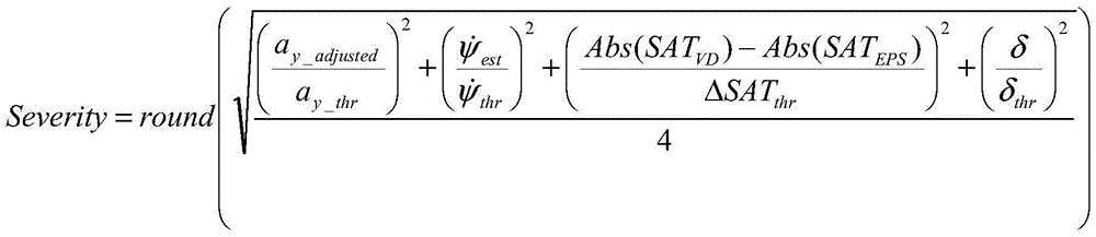
Optionally, the performing a fault severity evaluation on the determined potential wheel alignment imbalance includes:
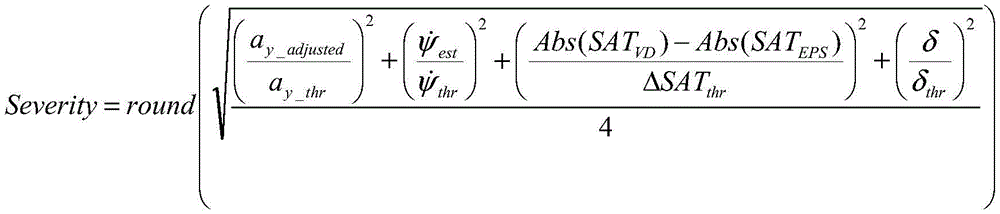
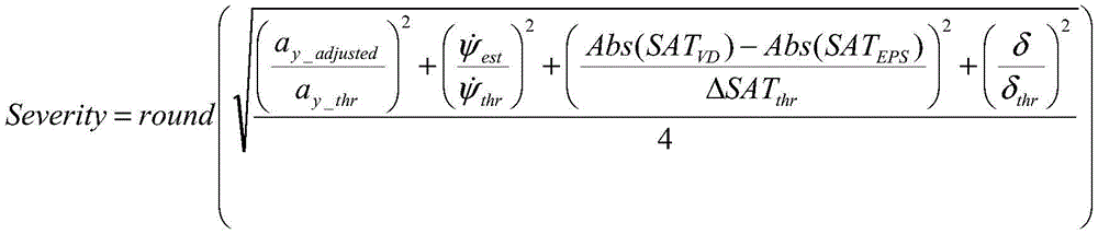
and performing fault severity evaluation on the determined potential wheel alignment imbalance according to a preset evaluation formula to obtain a fault severity evaluation value, wherein the evaluation formula comprises:
wherein the sensitivity represents the reasonBarrier severity assessment value, round () represents rounding, a
y_adjusted Represents the lateral acceleration adjustment value, a
y_thr A lateral acceleration adjustment threshold value is indicated,
represents a calculated yaw angular velocity, and/or>
Indicating yaw-rate threshold, SAT
VD Indicating a second self-aligning torque, SAT
EPS Representing the first self-aligning torque, Δ SAT
thr A threshold value representing a difference between the second self-aligning torque and the first self-aligning torque, δ representing a steering angle of the driver, δ
thr Represents a driving steering angle threshold value, and Abs () represents an absolute value.
Optionally, after the fault severity evaluation is performed on the potential wheel alignment imbalance determined this time and the fault severity evaluation value is obtained, the method further includes:
acquiring the category and the fault severity evaluation value corresponding to the vehicle after the vehicle is judged to have the potential wheel alignment disorder every time, and acquiring potential disorder information;
and if the potential misalignment information meets a second preset condition within a second preset time, generating alarm information, wherein the alarm information is used for prompting that the vehicle has the determined wheel alignment misalignment.
Optionally, the second preset condition includes:
acquiring that the category is that the number of camber deviation is greater than a first preset number, and the fault severity evaluation value is greater than a preset first evaluation threshold;
or,
and acquiring that the type is that the times of toe-in misalignment are greater than a second preset time, and the fault severity evaluation value is greater than a preset second evaluation threshold value.
A second aspect of an embodiment of the present invention provides a wheel alignment misalignment detection apparatus, including:
the device comprises a sensor information acquisition unit, a data processing unit and a data processing unit, wherein the sensor information acquisition unit is used for acquiring sensor information in the running process of a vehicle, and the sensor information comprises a lateral acceleration measurement value from a lateral accelerometer and a vehicle yaw rate from a yaw rate sensor;
the vehicle speed acquisition unit is used for acquiring the vehicle speed of the vehicle in the advancing direction;
a first calculation unit that calculates a lateral acceleration offset amount and a lateral acceleration adjustment value of the vehicle based on the lateral acceleration measurement value, the vehicle yaw rate, and a vehicle speed of the vehicle in a forward direction;
a wheel misalignment determination unit configured to determine whether there is a wheel misalignment of the vehicle based on the lateral acceleration offset and the lateral acceleration adjustment value;
a wheel alignment misalignment evaluation unit for determining wheel alignment misalignment information of the vehicle based on a result of the judgment by the wheel misalignment judgment unit and the lateral acceleration shift amount calculated by the first calculation unit.
A third aspect of embodiments of the present invention provides a terminal, including a memory, a processor, and a computer program stored in the memory and executable on the processor, wherein the processor implements the steps of the method for detecting wheel alignment misalignment according to any one of the above methods when executing the computer program.
A fourth aspect of the embodiments of the present invention provides a computer-readable storage medium storing a computer program which, when executed by a processor, implements the steps of the method for detecting wheel alignment misalignment according to any one of the above-described methods.
Compared with the prior art, the invention has the following beneficial effects:
according to the invention, the lateral acceleration offset and the lateral acceleration adjustment value of the vehicle are calculated by acquiring the sensor information in the running process of the vehicle and the speed of the vehicle in the advancing direction; judging whether the vehicle has wheel misalignment or not based on the lateral acceleration offset and the lateral acceleration adjustment value; determining wheel-alignment-misalignment information of the vehicle based on a result of the determination and the lateral acceleration offset amount. Therefore, the invention can realize the detection and judgment of the wheel alignment disorder of the vehicle, and can remind the vehicle operator to maintain and correct and position the vehicle when the wheel alignment disorder exists in the vehicle, thereby reducing the tire wear, improving the perception reliability and quality of the vehicle, and ensuring the timely detection and fault isolation.
Detailed Description
In the following description, for purposes of explanation and not limitation, specific details are set forth such as particular system structures, techniques, etc. in order to provide a thorough understanding of the embodiments of the invention. It will be apparent, however, to one skilled in the art that the present invention may be practiced in other embodiments that depart from these specific details. In other instances, detailed descriptions of well-known systems, devices, circuits, and methods are omitted so as not to obscure the description of the present invention with unnecessary detail.
In order to make the objects, technical solutions and advantages of the present invention more apparent, the following description is made by way of specific embodiments with reference to the accompanying drawings.
Referring to fig. 1, a schematic plan view of a multi-wheeled vehicle using an electric power steering system according to an embodiment of the present invention is shown.
As shown in fig. 1, wherein the depictions are for the purpose of illustrating certain exemplary embodiments only and not for the purpose of limiting the same, fig. 1 schematically illustrates a mobile platform in the form of a wheeled ground vehicle 10. Vehicle 10 may include any mobile platform, including, by way of non-limiting example, a passenger vehicle, a light or heavy truck, a utility vehicle, an agricultural vehicle, an industrial/warehouse vehicle, a recreational off-road vehicle, a robotic device, or an aerial device. In certain embodiments, the vehicle 10 includes two front wheels 60 and two rear wheels 70, and a steering wheel 20 operatively connected to the power steering system 40. The operator controls the direction of the steerable front wheels 60 by interacting with the steering wheel 20 that controls the power steering system 40, thereby controlling the direction of travel of the vehicle 10. In some embodiments, the power steering system 40 is an electric power steering system. The steering wheel 20 is equipped with a steering wheel angle sensor 22 for monitoring operator input in the form of steering commands. Other steering sensors include a pinion angle sensor 42, a motor torque sensor 44, and a steering torque sensor 46. In certain embodiments, the power steering torque assist developed by the eps system may be determined based on the motor torque sensor 44 multiplied by the steering ratio. In one embodiment, the front wheels 60 are steerable relative to the longitudinal axis 35 of the vehicle 10 to provide steering capability and the rear wheels 70 are fixed relative to the longitudinal axis 35 of the vehicle 10, although the concepts described herein are applicable to four-wheel steered vehicles and rear-wheel steered vehicles.
The vehicle 10 is preferably equipped with other sensors, including a vehicle speed sensor 16, a lateral accelerometer 14, and a yaw rate sensor 12. The vehicle 10 is also equipped with a left front wheel speed sensor 62, a right front wheel speed sensor 64, and a left rear wheel speed sensor 72, a right rear wheel speed sensor 74, respectively. The rotational speed sensor, including the wheel speed sensor, may be any suitable sensor, such as a hall effect sensor or an optical device. In some embodiments, the yaw-rate sensor 12 is a gyroscopic device that measures the angular velocity of the vehicle about its vertical axis, where the angle between the heading of the vehicle and the actual direction of motion of the vehicle is referred to as the slip angle, which is related to the yaw-rate. The lateral accelerometer 14 may be any suitable sensing device capable of monitoring lateral acceleration. The sensors communicate with the controller 30 through a direct wired link or communication bus 32.
The following may describe the method for detecting wheel alignment misalignment according to the embodiment of the present application, by referring to the vehicle described in fig. 1 as an embodiment.
Referring to fig. 2, it shows a flowchart of an implementation of the method for detecting wheel alignment misalignment according to the embodiment of the present invention, which is detailed as follows:
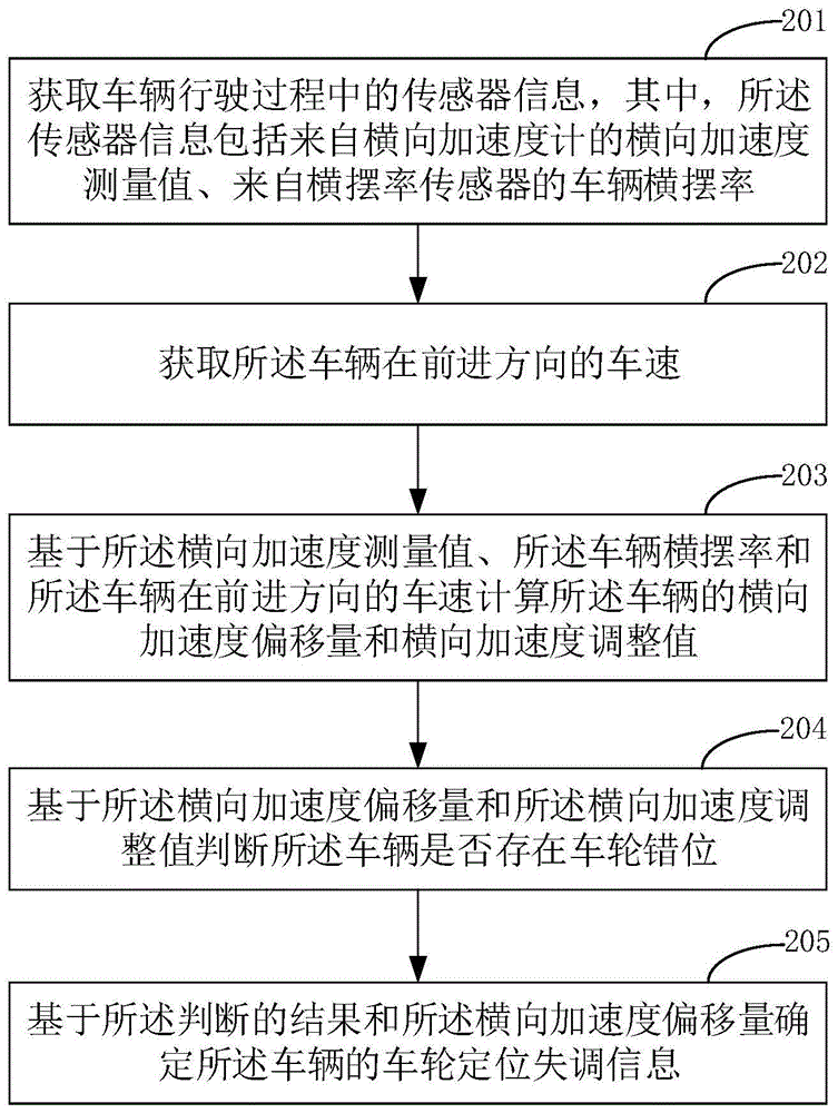
in step 201, sensor information during vehicle driving is acquired, wherein the sensor information includes lateral acceleration measurements from a lateral accelerometer and vehicle yaw rate from a yaw rate sensor.
In an embodiment of the present invention, in conjunction with FIG. 1, the sensor information described above may include vehicle speed calculated from the monitoring status of the steering wheel angle sensor 22, pinion angle sensor 42, power steering motor torque sensor 44, steering torque sensor 46, vehicle speed sensor 16, or in another embodiment, power steering torque assist, from the left and right front wheel speed sensors 62, 64 and left and right rear wheel speed sensors 72, 74, respectively, lateral accelerometer 14, yaw rate sensor 12, other suitable sensors or sensing mechanisms (e.g., based on other inputs and/or simulated executable models).
Wherein the acquired sensor information may include lateral acceleration measurements from a lateral accelerometer, vehicle yaw rate from a yaw rate sensor, for calculating lateral acceleration offsets and lateral acceleration adjustments of the vehicle.
In step 202, acquiring the vehicle speed of the vehicle in the forward direction;
in the embodiment of the invention, the vehicle speed of the vehicle in the forward direction can be obtained by calculation based on the vehicle speed sensor and also based on other sensors.
Calculating a lateral acceleration offset and a lateral acceleration adjustment value of the vehicle based on the lateral acceleration measurement, the vehicle yaw rate, and a vehicle speed of the vehicle in a forward direction in step 203;
optionally, step 203 may include:
calculating a lateral acceleration actual value of the vehicle based on the vehicle yaw rate and a vehicle speed of the vehicle in a forward direction;
calculating the difference between the actual value of the transverse acceleration and the measured value of the transverse acceleration to obtain the offset of the transverse acceleration;
a lateral acceleration adjustment value of the vehicle is calculated based on the lateral acceleration offset.
Specifically, in the embodiment of the invention, the actual value of the lateral acceleration of the vehicle may be calculated based on the yaw rate of the vehicle and the vehicle speed of the vehicle in the forward direction from an equation of motion, which may be expressed as:
wherein, a
y Representing the actual value of the lateral acceleration, V
x Indicates the vehicle speed in the forward direction>
Represents the lateral speed of the vehicle>
Indicating the vehicle yaw rate. During steady-state operation of the vehicle, the transverse vehicle speed is 0, so the above equation of motion can be expressed as->
Due to some road condition effects, the measured value of the lateral accelerometer is offset from the actual value of the lateral acceleration of the vehicle, and the measured value of the lateral accelerometer can be represented as a ym =a y + gsin φ, wherein, a ym Represents the lateral accelerometer measurements, g represents the gravitational constant, and phi represents the tilt angle.
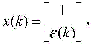
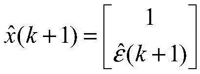
The mathematical representation of the vehicle lateral acceleration can be defined by the following state vector x:
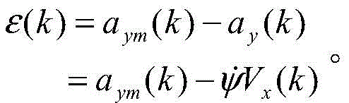
the state vector is controlled by a linear random difference equation x (k + 1) = x (k) + v (k); the measured value y can be represented by the following formula:
where ε (k) is the offset term, a Kalman filter may be used to determine the lateral acceleration at instant k, as follows:
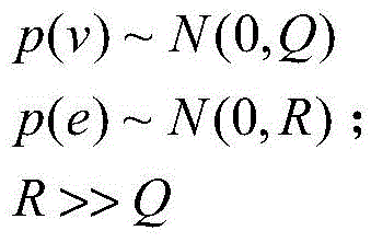
where the random variables v (k) and e (k) represent process noise and measurement noise, respectively. They are assumed to be independent of each other, white, and have a normal probability distribution. Then there is a signal model:
where Q and R are the covariances of v and e, respectively.
A kalman filter is applied to estimate the difference between the measured lateral acceleration and the actual lateral acceleration. Consider the above signal model and assume that the initial state and noise sequence are gaussian. Is provided with
Represents the conditional mean of a given observation x (k + 1) that { y (k) } precedes (includes) time k, and then ^ s>
The following recursions are satisfied:
S(k+1)=P(k)+Q(k)
L(k)=S(k)H T (k)(H(k)S(k)H T (k)+R(k)) -1
P(k+1)=S(k+1)-L(k)H(k)S(k+1)
where L (k) is the filter gain and P (k) is the state error covariance.
Then, calculating the difference between the actual value of the lateral acceleration and the measured value of the lateral acceleration to obtain the offset a of the lateral acceleration y_offset (k) (ii) a In particular, the lateral acceleration offset a y_offset The following were determined:
finally, a lateral acceleration adjustment value of the vehicle is calculated based on the lateral acceleration offset.
Specifically, in the embodiment of the invention, the adjusted transverse acceleration term a y_adjusted The following can be determined: a is y_adjusted =a ym -a y_offset 。
In an embodiment of the present invention, with the acquired sensor information of the vehicle 10, the lateral movement state of the vehicle 10 may be evaluated, which may be determined based on the following parameters: the lateral acceleration offset and the lateral acceleration adjustment value of the vehicle, whether the vehicle has a wheel misalignment, the first self-aligning torque, and the second self-aligning torque.
In step 204, judging whether the vehicle has wheel misalignment or not based on the lateral acceleration offset and the lateral acceleration adjustment value;
in an embodiment of the present invention, the wheel misalignment indicates a state in which the wheels of the vehicle are misaligned.
Optionally, in one embodiment, in order to determine whether the vehicle has a misaligned wheel, the sensor information further includes a yaw rate measurement value from a yaw angle sensor, and a steering angle value from a steering angle sensor; the judgment process is as follows:
first, a yaw rate calculation value of the vehicle is calculated;
the specific calculation process is as follows:
wherein, delta
b =δ-K
u gsin(φ)=δ-K
u a
y_offset ,
Wherein, K
u For understeer coefficient, can be defined as
Wherein, C f Cornering stiffness of two tires of the front axle, C r Is the steering stiffness of the two tires of the rear axle, W is the vehicle weight, L is the wheelbase, V x Indicating the vehicle speed.
Secondly, calculating a lateral acceleration calculation value of the vehicle based on the yaw angular velocity calculation value and the steering angle value;
if the measured value of the yaw angular velocity, the calculated value of the yaw angular velocity, the adjusted value of the lateral acceleration and the calculated value of the lateral acceleration meet a first preset condition, and the duration time meeting the first preset condition is longer than a first preset duration, determining that the vehicle has wheel dislocation; for example, the first preset time period may be 3 seconds.
Wherein the first preset condition comprises: the absolute value of the measured yaw-rate value is less than a preset first angular-rate threshold value, the absolute value of the difference between the calculated yaw-rate value and the measured yaw-rate value is greater than a preset second angular-rate threshold value, the absolute value of the lateral acceleration adjustment value is less than a preset first acceleration threshold value, the absolute value of the difference between the calculated lateral acceleration value and the lateral acceleration adjustment value is greater than a preset second acceleration threshold value, and the velocity in the forward direction of the vehicle is greater than a preset velocity threshold value (for example, the velocity threshold value may be 20 km/h).
In step 205, wheel-alignment-misalignment information of the vehicle is determined based on the result of the determination and the lateral acceleration offset amount.
In the embodiment of the present invention, the wheel alignment disorder of the vehicle can be evaluated by the above-determined lateral movement state of the vehicle, the wheel alignment disorder information of the vehicle is obtained, and further operations can be performed based on the wheel alignment disorder information.
Optionally, step 205 may include:
and if the vehicle has wheel misalignment and the lateral acceleration offset is smaller than an offset threshold value in a minimum time period, determining that the vehicle has potential wheel mispositioning.
In one embodiment, after the determining that the vehicle has the potential wheel alignment disorder, the method may further include:
determining the category corresponding to the potential wheel alignment maladjustment judged this time;
and evaluating the severity of the fault of the potential wheel alignment maladjustment determined at this time to obtain an evaluation value of the severity of the fault.
In one embodiment, before the determining the category corresponding to the potential wheel alignment misalignment of the current determination, the method may further include:
a first self-aligning torque representing the torque produced by coulomb and viscous friction generated by the power steering system during vehicle operation and a second self-aligning torque representing the lateral torque produced by the force acting on the vehicle from movement of the tire on the road surface are calculated.
Correspondingly, the determining the category corresponding to the potential wheel alignment misalignment determined this time includes:
and determining the category corresponding to the potential wheel alignment disorder determined at this time based on the first self-alignment torque and the second self-alignment torque.
Optionally, in an embodiment, the determining the category corresponding to the potential wheel alignment misalignment based on the first self-alignment torque and the second self-alignment torque may include:
calculating a difference between an absolute value of the second self-aligning torque and an absolute value of the first self-aligning torque;
if the difference is smaller than a preset negative threshold value, determining that the fault type is toe-in misalignment;
and if the difference is larger than a preset positive threshold, determining that the fault type is camber angle deviation, wherein the absolute value of the negative threshold is equal to the positive threshold.
In particular, depending on the operation of the power steering system and the motor/rack and pinion dynamics, the first self-aligning torque may be estimated or otherwise determined using an extended observation model assuming nominal parameters of the motor/rack parameters. The motor/rack parameters may include signal inputs from steering system sensors and actuators, which may include, by way of non-limiting example, a steering wheel angle sensor 22, a pinion angle sensor 42, a power steering torque assist sensor 44, and a steering torque sensor 46. The first self-aligning torque determined according to the operation of the power steering system may be determined as follows:
wherein, T
ts Is a signal from the steering
wheel torque sensor 46; j. the design is a square
eq Is an inertia element which can be determined according to the inertia of the rack and pinion and the inertia of the EPS motor;
is a pinion angle;
Is the derivative of the pinion angle; w is an external disturbance; b is
eq The damping component can be determined according to the damping of the rack and the gear and the damping coefficient of the EPS motor; c
fr Is the coulomb friction force on the steering rack.
The first self-aligning torque based on the power steering system and motor/rack and pinion dynamics describes the torque generated by coulomb friction and viscous friction generated by the power steering system during vehicle operation. Power steering System (SAT) based EPS And operation of the motor/rack and pinion dynamics to determine the first self-aligning torque may be referred to patent application No. 201811418159.X, which is incorporated herein by reference.
Second self-aligning torque (SAT) based on vehicle dynamics VD May be estimated or determined in the following manner:
wherein L is
p Is the pneumatic guide rail, delta is the steering angle, a
y Is a lateral acceleration, a is a lateral acceleration, b is a distance from the center of gravity of the vehicle to the front axle, is a distance from the center of gravity of the vehicle to the rear axle thereof,
is the yaw rate.
Likewise, the above estimation process may refer to patent application No. 201811418159.X, which is incorporated herein by reference.
The determining the category corresponding to the potential wheel alignment misalignment of the current determination based on the first self-alignment torque and the second self-alignment torque comprises:
calculating a difference between an absolute value of the second self-aligning torque and an absolute value of the first self-aligning torque;
if the difference is smaller than a preset negative threshold value, determining that the fault type is toe-in misalignment;
and if the difference is larger than a preset positive threshold, determining that the fault type is camber angle deviation, wherein the absolute value of the negative threshold is equal to the positive threshold.
In the embodiment of the present invention, the category corresponding to the potential wheel alignment misalignment includes toe misalignment and camber deviation, and the category corresponding to the potential wheel alignment misalignment can be determined by the above condition determination.
Optionally, in an embodiment, the performing a fault severity evaluation on the determined potential wheel alignment imbalance includes:
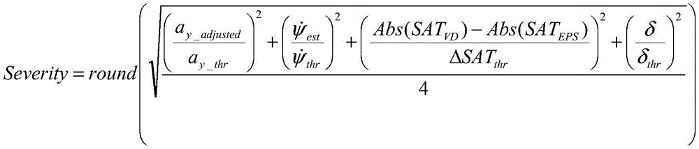
and performing fault severity evaluation on the determined potential wheel alignment imbalance according to a preset evaluation formula to obtain a fault severity evaluation value, wherein the evaluation formula comprises:
wherein, the Severity represents the evaluation value of the fault Severity, round () represents rounding, a
y_adjusted Represents the lateral acceleration adjustment value, a
y_thr A lateral acceleration adjustment threshold value is indicated,
represents a calculated yaw angular velocity, and/or>
Indicating yaw-rate threshold, SAT
VD Indicating a second self-aligning torque, SAT
EPS Representing the first self-aligning torque, Δ SAT
thr A threshold value representing a difference between the second self-aligning torque and the first self-aligning torque, δ representing a steering angle of the driver, δ
thr Represents a driving steering angle threshold value, and Abs () represents an absolute value.
Optionally, in an embodiment, after obtaining the failure severity evaluation value, the performing failure severity evaluation on the potential wheel alignment imbalance determined this time may further include:
acquiring the category and the fault severity evaluation value corresponding to the vehicle after the vehicle is judged to have the potential wheel alignment disorder every time to obtain potential disorder information;
and if the potential misalignment information meets a second preset condition within a second preset time, generating alarm information, wherein the alarm information is used for prompting that the vehicle has the determined wheel alignment misalignment.
Wherein the second preset condition comprises:
acquiring that the category is that the number of camber deviation is greater than a first preset number, and the fault severity evaluation value is greater than a preset first evaluation threshold;
or,
and acquiring that the type is that the times of toe-in misalignment are greater than a second preset time, and the fault severity evaluation value is greater than a preset second evaluation threshold value.
In the embodiment of the present invention, the second preset time period may be set to a unit of day, for example, 7 days, and the first preset number and the second preset number may be the same, for example, 4 times, or may be different, which is not limited herein.
Illustratively, by acquiring and counting potential misalignment information within 7 days, if more than 4 times of determinations are acquired within 7 days, and the 4 wheel misalignment categories are camber angle deviations, and the 4 wheel misalignment (camber angle deviation) fault severity evaluation values are all greater than a first evaluation threshold, the vehicle is considered to have a certain wheel misalignment, and warning information is generated to instruct a vehicle operator to perform corresponding maintenance and correction operations.
Illustratively, by acquiring and counting potential misalignment information within 7 days, if it is determined that the vehicle has potential wheel alignment misalignment within 7 days for more than 4 times, and the categories of the 4 times of wheel alignment misalignment are toe misalignment, and the evaluation values of the severity of the 4 times of wheel alignment misalignment (toe misalignment) fault are all greater than a second evaluation threshold, the vehicle is considered to have determined wheel alignment misalignment, and warning information is generated to instruct a vehicle operator to perform corresponding maintenance and correction operations.
According to the method, the lateral acceleration offset and the lateral acceleration adjustment value of the vehicle are calculated by acquiring the sensor information in the running process of the vehicle and the speed of the vehicle in the advancing direction; judging whether the vehicle has wheel dislocation or not based on the lateral acceleration offset and the lateral acceleration adjustment value; determining wheel-alignment-misalignment information of the vehicle based on a result of the determination and the lateral acceleration offset amount. Therefore, the invention can realize the detection and judgment of the wheel alignment disorder of the vehicle, and can remind the vehicle operator to maintain, correct and position the vehicle when the wheel alignment disorder exists in the vehicle, thereby reducing the tire wear, improving the perception reliability and quality of the vehicle, and ensuring the timely detection and fault isolation.
It should be understood that, the sequence numbers of the steps in the foregoing embodiments do not imply an execution sequence, and the execution sequence of each process should be determined by its function and inherent logic, and should not constitute any limitation to the implementation process of the embodiments of the present invention.
The following are embodiments of the apparatus of the invention, reference being made to the corresponding method embodiments described above for details which are not described in detail therein.
Fig. 3 is a schematic structural diagram of a wheel alignment misalignment detection apparatus according to an embodiment of the present invention, and for convenience of description, only the portions related to the embodiment of the present invention are shown, and the details are as follows:
as shown in fig. 3, the wheel alignment disorder detecting apparatus 300 includes: a sensor information acquisition unit 301, a vehicle speed acquisition unit 302, a first calculation unit 303, a wheel misalignment determination unit 304, and a wheel misregistration evaluation unit 305.
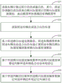
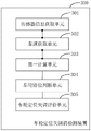
A sensor information acquiring unit 301, configured to acquire sensor information during vehicle driving, where the sensor information includes a lateral acceleration measurement value from a lateral accelerometer and a vehicle yaw rate from a yaw rate sensor;
a vehicle speed obtaining unit 302, configured to obtain a vehicle speed of the vehicle in a forward direction;
a first calculation unit 303 for calculating a lateral acceleration offset amount and a lateral acceleration adjustment value of the vehicle based on the lateral acceleration measurement value, the vehicle yaw rate, and a vehicle speed of the vehicle in a forward direction;
a wheel misalignment determination unit 304 for determining whether there is a wheel misalignment of the vehicle based on the lateral acceleration offset amount and the lateral acceleration adjustment value;
a wheel alignment disorder evaluation unit 305 for determining wheel alignment disorder information of the vehicle based on the result of the judgment by the wheel misalignment judgment unit 304 and the lateral acceleration shift amount calculated by the first calculation unit 303.
Optionally, the first calculating unit 303 is specifically configured to:
calculating a lateral acceleration actual value of the vehicle based on the vehicle yaw rate and a vehicle speed of the vehicle in a forward direction;
calculating the difference between the actual value of the transverse acceleration and the measured value of the transverse acceleration to obtain the offset of the transverse acceleration;
a lateral acceleration adjustment value of the vehicle is calculated based on the lateral acceleration offset.
Optionally, the sensor information includes a lateral acceleration measurement from a lateral accelerometer, a vehicle yaw rate from a yaw rate sensor, and the first calculation unit 303 is further configured to:
calculating a yaw rate calculation value of the vehicle;
calculating a lateral acceleration calculation value of the vehicle based on the yaw rate calculation value and the steering angle value;
accordingly, the wheel misalignment determination unit 304 is specifically configured to:
if the measured value of the yaw angular velocity, the calculated value of the yaw angular velocity, the adjusted value of the lateral acceleration and the calculated value of the lateral acceleration meet a first preset condition, and the duration time meeting the first preset condition is longer than a first preset duration, determining that the vehicle has wheel dislocation;
wherein the first preset condition comprises: the absolute value of the measured value of the yaw rate is smaller than a preset first angular velocity threshold value, the absolute value of the difference between the calculated value of the yaw rate and the measured value of the yaw rate is larger than a preset second angular velocity threshold value, the absolute value of the adjusted value of the lateral acceleration is smaller than a preset first acceleration threshold value, the absolute value of the difference between the calculated value of the lateral acceleration and the adjusted value of the lateral acceleration is larger than a preset second acceleration threshold value, and the speed in the advancing direction of the vehicle is larger than a preset speed threshold value.
Optionally, the wheel alignment misalignment evaluation unit 305 is specifically configured to determine that the vehicle has a potential wheel alignment misalignment if the vehicle has a wheel misalignment and the lateral acceleration offset is smaller than an offset threshold within a minimum time period.
Optionally, the wheel alignment maladjustment detecting apparatus 300 further comprises:
a category determination unit configured to determine a category corresponding to the potential wheel alignment misalignment determined this time after the vehicle is determined to have the potential wheel alignment misalignment;
and a severity evaluation unit for performing a fault severity evaluation on the potential wheel alignment disorder determined this time to obtain a fault severity evaluation value.
Optionally, the first calculating unit 303 is further configured to: and calculating a first self-aligning torque and a second self-aligning torque before determining the category corresponding to the potential wheel alignment disorder determined this time, wherein the first self-aligning torque represents the torque generated by coulomb friction and viscous friction generated by a power steering system during the running of the vehicle, and the second self-aligning torque represents the lateral torque generated by the force applied to the vehicle by the movement of the tire on the road surface.
Correspondingly, the category determining unit is specifically configured to: and determining the category corresponding to the potential wheel alignment disorder determined at this time based on the first self-alignment torque and the second self-alignment torque.
Optionally, the wheel alignment maladjustment detecting apparatus 300 further comprises:
a difference value calculation unit for calculating a difference between an absolute value of the second self-aligning torque and an absolute value of the first self-aligning torque;
the category determining unit is specifically further configured to determine that the fault category is toe-in misalignment if the difference is smaller than a preset negative threshold; and if the difference is larger than a preset positive threshold, determining that the fault type is camber deviation, wherein the absolute value of the negative threshold is equal to the positive threshold.
Optionally, the severity evaluation unit is specifically configured to perform fault severity evaluation on the determined potential wheel alignment imbalance according to a preset evaluation formula to obtain a fault severity evaluation value, where the evaluation formula includes:
wherein, the Severity represents the evaluation value of the fault Severity, round () represents rounding, a
y_adjusted Represents the lateral acceleration adjustment value, a
y_thr A lateral acceleration adjustment threshold value is indicated,
represents a calculated yaw rate value>
Indicating yaw-rate threshold, SAT
VD Indicating a second self-aligning torque, SAT
EPS Representing the first self-aligning torque, Δ SAT
thr A threshold value representing a difference between the second self-aligning torque and the first self-aligning torque, δ representing a steering angle of the driver, δ
thr Represents a driving steering angle threshold value, and Abs () represents an absolute value.
Optionally, the wheel alignment misalignment detection apparatus 300 further includes:
a potential misalignment information statistic unit, configured to perform fault severity evaluation on the determined potential wheel alignment misalignment, and after obtaining a fault severity evaluation value, obtain the category and the fault severity evaluation value corresponding to each determination that the vehicle has the potential wheel alignment misalignment, so as to obtain potential misalignment information;
the warning unit is used for generating warning information if the potential misalignment information meets a second preset condition within a second preset time length, wherein the warning information is used for prompting that the vehicle has the determined wheel alignment misalignment;
wherein the second preset condition comprises:
acquiring that the category is that the number of camber angle deviations is greater than a first preset number, and the fault severity evaluation value is greater than a preset first evaluation threshold;
or,
and acquiring that the type is that the times of toe-in misalignment are greater than a second preset time, and the fault severity evaluation value is greater than a preset second evaluation threshold value.
According to the method, the lateral acceleration offset and the lateral acceleration adjustment value of the vehicle are calculated by acquiring the sensor information of the vehicle in the running process and the vehicle speed of the vehicle in the advancing direction; judging whether the vehicle has wheel misalignment or not based on the lateral acceleration offset and the lateral acceleration adjustment value; determining wheel-alignment-misalignment information of the vehicle based on a result of the determination and the lateral acceleration offset amount. Therefore, the invention can realize the detection and judgment of the wheel alignment disorder of the vehicle, and can remind the vehicle operator to maintain, correct and position the vehicle when the wheel alignment disorder exists in the vehicle, thereby reducing the tire wear, improving the perception reliability and quality of the vehicle, and ensuring the timely detection and fault isolation.
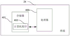
Fig. 4 is a schematic diagram of a terminal according to an embodiment of the present invention. As shown in fig. 4, the terminal Z4 of this embodiment includes: a processor 400, a memory 401 and a computer program 402 stored in said memory 401 and executable on said processor 400. The processor 400 executes the computer program 402 to implement the steps of the above-mentioned embodiments of the wheel misalignment detection method, such as the steps 201 to 205 shown in fig. 2. Alternatively, the processor 400, when executing the computer program 402, implements the functions of the modules/units in the above-mentioned device embodiments, such as the functions of the units 301 to 305 shown in fig. 3.
Illustratively, the computer program 402 can be partitioned into one or more modules/units, which are stored in the memory 401 and executed by the processor 400 to implement the present invention. The one or more modules/units may be a series of computer program instruction segments capable of performing specific functions, which are used to describe the execution of the computer program 402 in the terminal Z4. For example, the computer program 402 may be divided into a sensor information acquisition unit, a vehicle speed acquisition unit, a first calculation unit, a wheel misalignment determination unit, and a wheel misalignment evaluation unit, and the functions of the units are as follows:
the device comprises a sensor information acquisition unit, a data processing unit and a data processing unit, wherein the sensor information acquisition unit is used for acquiring sensor information in the running process of a vehicle, and the sensor information comprises a lateral acceleration measurement value from a lateral accelerometer and a vehicle yaw rate from a yaw rate sensor;
the vehicle speed acquisition unit is used for acquiring the vehicle speed of the vehicle in the advancing direction;
a first calculation unit that calculates a lateral acceleration offset amount and a lateral acceleration adjustment value of the vehicle based on the lateral acceleration measurement value, the vehicle yaw rate, and a vehicle speed of the vehicle in a forward direction;
a wheel misalignment determination unit configured to determine whether there is a wheel misalignment of the vehicle based on the lateral acceleration offset and the lateral acceleration adjustment value;
a wheel alignment misalignment evaluation unit for determining wheel alignment misalignment information of the vehicle based on a result of the judgment by the wheel misalignment judgment unit and the lateral acceleration shift amount calculated by the first calculation unit.
The terminal Z4 may be a desktop computer, a notebook, a palm computer, a cloud server, or other computing device. The terminal may include, but is not limited to, a processor 400, a memory 401. It will be appreciated by those skilled in the art that fig. 4 is only an example of a terminal Z4 and does not constitute a limitation to terminal Z4, and may include more or less components than those shown, or some components in combination, or different components, for example, the terminal may also include input output devices, network access devices, buses, etc.
The Processor 400 may be a Central Processing Unit (CPU), other general purpose Processor, a Digital Signal Processor (DSP), an Application Specific Integrated Circuit (ASIC), a Field Programmable Gate Array (FPGA) or other Programmable logic device, discrete Gate or transistor logic, discrete hardware components, etc. A general purpose processor may be a microprocessor or the processor may be any conventional processor or the like.
The storage 401 may be an internal storage unit of the terminal, such as a hard disk or a memory of the terminal. The memory 401 may also be an external storage device of the terminal, such as a plug-in hard disk, a Smart Media Card (SMC), a Secure Digital (SD) Card, a Flash memory Card (Flash Card), and the like, which are equipped on the terminal. Further, the memory 401 may also include both an internal storage unit and an external storage device of the terminal. The memory 401 is used for storing the computer program and other programs and data required by the terminal. The memory 401 may also be used to temporarily store data that has been output or is to be output.
It will be apparent to those skilled in the art that, for convenience and brevity of description, only the above-mentioned division of the functional units and modules is illustrated, and in practical applications, the above-mentioned function distribution may be performed by different functional units and modules according to needs, that is, the internal structure of the apparatus is divided into different functional units or modules to perform all or part of the above-mentioned functions. Each functional unit and module in the embodiments may be integrated in one processing unit, or each unit may exist alone physically, or two or more units are integrated in one unit, and the integrated unit may be implemented in a form of hardware, or in a form of software functional unit. In addition, specific names of the functional units and modules are only for convenience of distinguishing from each other, and are not used for limiting the protection scope of the present application. The specific working processes of the units and modules in the system may refer to the corresponding processes in the foregoing method embodiments, and are not described herein again.
In the above embodiments, the descriptions of the respective embodiments have respective emphasis, and reference may be made to the related descriptions of other embodiments for parts that are not described or illustrated in a certain embodiment.
Those of ordinary skill in the art will appreciate that the various illustrative elements and algorithm steps described in connection with the embodiments disclosed herein may be implemented as electronic hardware or combinations of computer software and electronic hardware. Whether such functionality is implemented as hardware or software depends upon the particular application and design constraints imposed on the implementation. Skilled artisans may implement the described functionality in varying ways for each particular application, but such implementation decisions should not be interpreted as causing a departure from the scope of the present invention.
In the embodiments provided in the present invention, it should be understood that the disclosed apparatus/terminal and method may be implemented in other ways. For example, the above-described apparatus/terminal embodiments are merely illustrative, and for example, the division of the modules or units is only one logical division, and there may be other divisions when actually implemented, for example, a plurality of units or components may be combined or may be integrated into another system, or some features may be omitted, or not executed. In addition, the shown or discussed mutual coupling or direct coupling or communication connection may be through some interfaces, indirect coupling or communication connection of devices or units, and may be in an electrical, mechanical or other form.
The units described as separate parts may or may not be physically separate, and parts displayed as units may or may not be physical units, may be located in one place, or may be distributed on a plurality of network units. Some or all of the units can be selected according to actual needs to achieve the purpose of the solution of the embodiment.
In addition, functional units in the embodiments of the present invention may be integrated into one processing unit, or each unit may exist alone physically, or two or more units are integrated into one unit. The integrated unit can be realized in a form of hardware, and can also be realized in a form of a software functional unit.
The integrated modules/units, if implemented in the form of software functional units and sold or used as separate products, may be stored in a computer readable storage medium. Based on such understanding, all or part of the flow of the method according to the embodiments of the present invention may also be implemented by a computer program, which may be stored in a computer-readable storage medium, and when the computer program is executed by a processor, the steps of the method embodiments described above may be implemented. Wherein the computer program comprises computer program code, which may be in the form of source code, object code, an executable file or some intermediate form, etc. The computer-readable medium may include: any entity or device capable of carrying the computer program code, recording medium, U.S. disk, removable hard disk, magnetic diskette, optical disk, computer Memory, read-Only Memory (ROM), random Access Memory (RAM), electrical carrier wave signal, telecommunications signal, and software distribution medium, etc. It should be noted that the computer readable medium may contain other components which may be suitably increased or decreased as required by legislation and patent practice in jurisdictions, for example, in some jurisdictions, computer readable media which may not include electrical carrier signals and telecommunications signals in accordance with legislation and patent practice.
The above-mentioned embodiments are only used to illustrate the technical solution of the present invention, and not to limit the same; although the present invention has been described in detail with reference to the foregoing embodiments, it will be understood by those of ordinary skill in the art that: the technical solutions described in the foregoing embodiments may still be modified, or some technical features may be equivalently replaced; such modifications and substitutions do not substantially depart from the spirit and scope of the embodiments of the present invention, and are intended to be included within the scope of the present invention.