CN112888884B - valve - Google Patents
valve Download PDFInfo
- Publication number
- CN112888884B CN112888884B CN201980067912.1A CN201980067912A CN112888884B CN 112888884 B CN112888884 B CN 112888884B CN 201980067912 A CN201980067912 A CN 201980067912A CN 112888884 B CN112888884 B CN 112888884B
- Authority
- CN
- China
- Prior art keywords
- valve
- valve stem
- valve body
- retaining member
- stem
- Prior art date
- Legal status (The legal status is an assumption and is not a legal conclusion. Google has not performed a legal analysis and makes no representation as to the accuracy of the status listed.)
- Active
Links
Images




Classifications
-
- A—HUMAN NECESSITIES
- A61—MEDICAL OR VETERINARY SCIENCE; HYGIENE
- A61M—DEVICES FOR INTRODUCING MEDIA INTO, OR ONTO, THE BODY; DEVICES FOR TRANSDUCING BODY MEDIA OR FOR TAKING MEDIA FROM THE BODY; DEVICES FOR PRODUCING OR ENDING SLEEP OR STUPOR
- A61M39/00—Tubes, tube connectors, tube couplings, valves, access sites or the like, specially adapted for medical use
- A61M39/10—Tube connectors; Tube couplings
- A61M39/16—Tube connectors; Tube couplings having provision for disinfection or sterilisation
-
- A—HUMAN NECESSITIES
- A61—MEDICAL OR VETERINARY SCIENCE; HYGIENE
- A61M—DEVICES FOR INTRODUCING MEDIA INTO, OR ONTO, THE BODY; DEVICES FOR TRANSDUCING BODY MEDIA OR FOR TAKING MEDIA FROM THE BODY; DEVICES FOR PRODUCING OR ENDING SLEEP OR STUPOR
- A61M39/00—Tubes, tube connectors, tube couplings, valves, access sites or the like, specially adapted for medical use
- A61M39/20—Closure caps or plugs for connectors or open ends of tubes
-
- A—HUMAN NECESSITIES
- A61—MEDICAL OR VETERINARY SCIENCE; HYGIENE
- A61M—DEVICES FOR INTRODUCING MEDIA INTO, OR ONTO, THE BODY; DEVICES FOR TRANSDUCING BODY MEDIA OR FOR TAKING MEDIA FROM THE BODY; DEVICES FOR PRODUCING OR ENDING SLEEP OR STUPOR
- A61M39/00—Tubes, tube connectors, tube couplings, valves, access sites or the like, specially adapted for medical use
- A61M39/22—Valves or arrangement of valves
-
- F—MECHANICAL ENGINEERING; LIGHTING; HEATING; WEAPONS; BLASTING
- F16—ENGINEERING ELEMENTS AND UNITS; GENERAL MEASURES FOR PRODUCING AND MAINTAINING EFFECTIVE FUNCTIONING OF MACHINES OR INSTALLATIONS; THERMAL INSULATION IN GENERAL
- F16K—VALVES; TAPS; COCKS; ACTUATING-FLOATS; DEVICES FOR VENTING OR AERATING
- F16K3/00—Gate valves or sliding valves, i.e. cut-off apparatus with closing members having a sliding movement along the seat for opening and closing
- F16K3/22—Gate valves or sliding valves, i.e. cut-off apparatus with closing members having a sliding movement along the seat for opening and closing with sealing faces shaped as surfaces of solids of revolution
- F16K3/24—Gate valves or sliding valves, i.e. cut-off apparatus with closing members having a sliding movement along the seat for opening and closing with sealing faces shaped as surfaces of solids of revolution with cylindrical valve members
- F16K3/26—Gate valves or sliding valves, i.e. cut-off apparatus with closing members having a sliding movement along the seat for opening and closing with sealing faces shaped as surfaces of solids of revolution with cylindrical valve members with fluid passages in the valve member
- F16K3/265—Gate valves or sliding valves, i.e. cut-off apparatus with closing members having a sliding movement along the seat for opening and closing with sealing faces shaped as surfaces of solids of revolution with cylindrical valve members with fluid passages in the valve member with a sleeve sliding in the direction of the flow line
-
- F—MECHANICAL ENGINEERING; LIGHTING; HEATING; WEAPONS; BLASTING
- F16—ENGINEERING ELEMENTS AND UNITS; GENERAL MEASURES FOR PRODUCING AND MAINTAINING EFFECTIVE FUNCTIONING OF MACHINES OR INSTALLATIONS; THERMAL INSULATION IN GENERAL
- F16K—VALVES; TAPS; COCKS; ACTUATING-FLOATS; DEVICES FOR VENTING OR AERATING
- F16K31/00—Actuating devices; Operating means; Releasing devices
- F16K31/44—Mechanical actuating means
- F16K31/52—Mechanical actuating means with crank, eccentric, or cam
- F16K31/528—Mechanical actuating means with crank, eccentric, or cam with pin and slot
- F16K31/5286—Mechanical actuating means with crank, eccentric, or cam with pin and slot comprising a sliding valve
-
- F—MECHANICAL ENGINEERING; LIGHTING; HEATING; WEAPONS; BLASTING
- F16—ENGINEERING ELEMENTS AND UNITS; GENERAL MEASURES FOR PRODUCING AND MAINTAINING EFFECTIVE FUNCTIONING OF MACHINES OR INSTALLATIONS; THERMAL INSULATION IN GENERAL
- F16K—VALVES; TAPS; COCKS; ACTUATING-FLOATS; DEVICES FOR VENTING OR AERATING
- F16K37/00—Special means in or on valves or other cut-off apparatus for indicating or recording operation thereof, or for enabling an alarm to be given
- F16K37/0025—Electrical or magnetic means
- F16K37/005—Electrical or magnetic means for measuring fluid parameters
-
- F—MECHANICAL ENGINEERING; LIGHTING; HEATING; WEAPONS; BLASTING
- F16—ENGINEERING ELEMENTS AND UNITS; GENERAL MEASURES FOR PRODUCING AND MAINTAINING EFFECTIVE FUNCTIONING OF MACHINES OR INSTALLATIONS; THERMAL INSULATION IN GENERAL
- F16K—VALVES; TAPS; COCKS; ACTUATING-FLOATS; DEVICES FOR VENTING OR AERATING
- F16K5/00—Plug valves; Taps or cocks comprising only cut-off apparatus having at least one of the sealing faces shaped as a more or less complete surface of a solid of revolution, the opening and closing movement being predominantly rotary
- F16K5/04—Plug valves; Taps or cocks comprising only cut-off apparatus having at least one of the sealing faces shaped as a more or less complete surface of a solid of revolution, the opening and closing movement being predominantly rotary with plugs having cylindrical surfaces; Packings therefor
- F16K5/0414—Plug channel at 90 degrees to the inlet
-
- F—MECHANICAL ENGINEERING; LIGHTING; HEATING; WEAPONS; BLASTING
- F16—ENGINEERING ELEMENTS AND UNITS; GENERAL MEASURES FOR PRODUCING AND MAINTAINING EFFECTIVE FUNCTIONING OF MACHINES OR INSTALLATIONS; THERMAL INSULATION IN GENERAL
- F16K—VALVES; TAPS; COCKS; ACTUATING-FLOATS; DEVICES FOR VENTING OR AERATING
- F16K5/00—Plug valves; Taps or cocks comprising only cut-off apparatus having at least one of the sealing faces shaped as a more or less complete surface of a solid of revolution, the opening and closing movement being predominantly rotary
- F16K5/04—Plug valves; Taps or cocks comprising only cut-off apparatus having at least one of the sealing faces shaped as a more or less complete surface of a solid of revolution, the opening and closing movement being predominantly rotary with plugs having cylindrical surfaces; Packings therefor
- F16K5/0442—Spindles and actuating means
-
- A—HUMAN NECESSITIES
- A61—MEDICAL OR VETERINARY SCIENCE; HYGIENE
- A61M—DEVICES FOR INTRODUCING MEDIA INTO, OR ONTO, THE BODY; DEVICES FOR TRANSDUCING BODY MEDIA OR FOR TAKING MEDIA FROM THE BODY; DEVICES FOR PRODUCING OR ENDING SLEEP OR STUPOR
- A61M39/00—Tubes, tube connectors, tube couplings, valves, access sites or the like, specially adapted for medical use
- A61M39/22—Valves or arrangement of valves
- A61M39/24—Check- or non-return valves
- A61M2039/2473—Valve comprising a non-deformable, movable element, e.g. ball-valve, valve with movable stopper or reciprocating element
- A61M2039/2486—Guided stem, e.g. reciprocating stopper
-
- A—HUMAN NECESSITIES
- A61—MEDICAL OR VETERINARY SCIENCE; HYGIENE
- A61M—DEVICES FOR INTRODUCING MEDIA INTO, OR ONTO, THE BODY; DEVICES FOR TRANSDUCING BODY MEDIA OR FOR TAKING MEDIA FROM THE BODY; DEVICES FOR PRODUCING OR ENDING SLEEP OR STUPOR
- A61M2205/00—General characteristics of the apparatus
- A61M2205/33—Controlling, regulating or measuring
-
- A—HUMAN NECESSITIES
- A61—MEDICAL OR VETERINARY SCIENCE; HYGIENE
- A61M—DEVICES FOR INTRODUCING MEDIA INTO, OR ONTO, THE BODY; DEVICES FOR TRANSDUCING BODY MEDIA OR FOR TAKING MEDIA FROM THE BODY; DEVICES FOR PRODUCING OR ENDING SLEEP OR STUPOR
- A61M2205/00—General characteristics of the apparatus
- A61M2205/58—Means for facilitating use, e.g. by people with impaired vision
- A61M2205/581—Means for facilitating use, e.g. by people with impaired vision by audible feedback
-
- A—HUMAN NECESSITIES
- A61—MEDICAL OR VETERINARY SCIENCE; HYGIENE
- A61M—DEVICES FOR INTRODUCING MEDIA INTO, OR ONTO, THE BODY; DEVICES FOR TRANSDUCING BODY MEDIA OR FOR TAKING MEDIA FROM THE BODY; DEVICES FOR PRODUCING OR ENDING SLEEP OR STUPOR
- A61M2205/00—General characteristics of the apparatus
- A61M2205/58—Means for facilitating use, e.g. by people with impaired vision
- A61M2205/582—Means for facilitating use, e.g. by people with impaired vision by tactile feedback
Landscapes
- Health & Medical Sciences (AREA)
- Engineering & Computer Science (AREA)
- General Engineering & Computer Science (AREA)
- Heart & Thoracic Surgery (AREA)
- Mechanical Engineering (AREA)
- Public Health (AREA)
- Veterinary Medicine (AREA)
- Life Sciences & Earth Sciences (AREA)
- Animal Behavior & Ethology (AREA)
- General Health & Medical Sciences (AREA)
- Biomedical Technology (AREA)
- Hematology (AREA)
- Anesthesiology (AREA)
- Pulmonology (AREA)
- Epidemiology (AREA)
- Lift Valve (AREA)
- Indication Of The Valve Opening Or Closing Status (AREA)
- Infusion, Injection, And Reservoir Apparatuses (AREA)
- Physics & Mathematics (AREA)
- Fluid Mechanics (AREA)
- Pharmacology & Pharmacy (AREA)
Abstract
本公开提供一种阀,所述阀包括:阀体;以及阀杆,所述阀杆至少部分地设置在所述阀体内,所述阀杆包括限定中心内腔的侧壁和所述侧壁中的至少一个开口,其中所述阀适于在所述至少一个开口设置在所述阀体内时防止流体流过所述内腔,以及在所述至少一个开口从所述阀体露出时允许流体流过所述内腔,并且其中所述阀基本上不包含弹簧。

The present disclosure provides a valve comprising: a valve body; and a valve stem at least partially disposed within the valve body, the valve stem including a side wall defining a central lumen and the side wall wherein the valve is adapted to prevent fluid from flowing through the lumen when the at least one opening is disposed in the valve body, and to allow fluid flow when the at least one opening is exposed from the valve body flow through the lumen, and wherein the valve is substantially free of springs.
Description
技术领域technical field
本公开涉及阀。This disclosure relates to valves.
背景技术Background technique
可利用阀来限制两个或多个流体导管之间的流体流动。具体地,阀可在制药和生物应用中用来例如在制备药物成分时,允许选择性地限制流体流动。Valves may be utilized to restrict fluid flow between two or more fluid conduits. In particular, valves are used in pharmaceutical and biological applications to allow selective restriction of fluid flow, for example in the manufacture of pharmaceutical compositions.
制药和生物工业持续要求改进阀设计,以最大程度地减少对流体成分的损坏并提高操作效率和无菌性。The pharmaceutical and bio industries continue to demand improved valve designs to minimize damage to fluid components and improve operational efficiency and sterility.
附图说明Description of drawings
实施例以实例的方式示出,并非旨在受到附图的限制。The embodiments are shown by way of example and are not intended to be limited by the figures.
图1包括根据一个实施例的阀的透视图。Figure 1 includes a perspective view of a valve according to one embodiment.
图2包括根据一个实施例的阀的阀杆的透视图。2 includes a perspective view of a valve stem of a valve according to one embodiment.
图3包括根据一个实施例的沿图2中的线A-A所见的阀杆的剖视图。3 includes a cross-sectional view of the valve stem as seen along line A-A in FIG. 2 according to one embodiment.
图4包括根据一个实施例的处于闭合构型的阀的剖视图。4 includes a cross-sectional view of a valve in a closed configuration according to one embodiment.
图5包括根据一个实施例的处于打开构型的阀杆的剖视图。5 includes a cross-sectional view of a valve stem in an open configuration according to one embodiment.
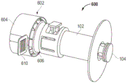
图6包括根据一个实施例的包括卫生级接头的阀的透视图。6 includes a perspective view of a valve including a sanitary fitting according to one embodiment.
图7包括根据一个实施例的处于打开构型的图6的阀的剖视图。7 includes a cross-sectional view of the valve of FIG. 6 in an open configuration, according to one embodiment.
图8包括根据一个实施例的包括传感器的阀的透视图。Figure 8 includes a perspective view of a valve including a sensor according to one embodiment.
图9包括根据一个实施例的处于打开构型的图8的阀的剖视图。9 includes a cross-sectional view of the valve of FIG. 8 in an open configuration, according to one embodiment.
图10和图11包括根据实施例的阀的透视图。10 and 11 include perspective views of a valve according to an embodiment.
图12包括根据一个实施例的阀的透视图。Figure 12 includes a perspective view of a valve according to one embodiment.
图13包括根据一个实施例的沿图12中的线B-B所见的图12的阀的剖视图。13 includes a cross-sectional view of the valve of FIG. 12 as seen along line B-B in FIG. 12 according to one embodiment.
具体实施方式Detailed ways
提供结合附图的以下描述以帮助理解本文所公开的教导内容。以下论述将集中于本教导内容的具体实施方式和实施例。提供该重点是为了帮助描述教导内容,并且不应该被解释为是对本教导内容的范围或适用性的限制。然而,其他实施例可基于本专利申请中所公开的教导内容而使用。The following description in conjunction with the accompanying figures is provided to assist in understanding the teachings disclosed herein. The following discussion will focus on specific implementations and examples of the present teachings. This emphasis is provided to aid in describing the teachings and should not be construed as limiting the scope or applicability of the teachings. However, other embodiments may be used based on the teachings disclosed in this patent application.
术语″由...构成″″包含″″包括″″含有″″具有″″有″或它们的任何其他变型旨在涵盖非排他性的包含之意。例如,包含特征列表的方法、制品或装置不一定仅限于那些特征,而是可以包括未明确列出的或这种方法、制品或装置固有的其他特征。另外,除非另有明确说明,否则″或″是指包括性的″或″而非排他性的″或″。例如,以下任何一项均可满足条件A或B:A为真(或存在的)而B为假(或不存在的)、A为假(或不存在的)而B为真(或存在的),以及A和B两者都为真(或存在的)。The terms "consisting of", "comprising", "including", "comprising", "having", "having" or any other variation thereof are intended to cover a non-exclusive sense of inclusion. For example, a method, article, or apparatus that includes a list of features is not necessarily limited to only those features, but may include other features not explicitly listed or inherent to such a method, article, or apparatus. In addition, unless otherwise expressly stated, "or" means an inclusive "or" rather than an exclusive "or". For example, either condition A or B can be satisfied by any of the following: A is true (or exists) and B is false (or does not exist), A is false (or does not exist) and B is true (or exists ), and both A and B are true (or exist).
术语″大体″、″基本上″、″大致″等旨在涵盖与给定值的偏差范围。在特定实施例中,术语″大体″、″基本上″、″大致″等是指在值的以下任一方向上的偏差:在值的10%内;在值的9%内;在值的8%内;在值的7%内;在值的6%内;在值的5%内;在值的4%of内;在值的3%内;在值的2%内;或在值的1%内。The terms "substantially", "substantially", "approximately" and the like are intended to cover a range of deviation from a given value. In particular embodiments, the terms "substantially", "substantially", "approximately" and the like refer to deviations in any of the following directions of a value: within 10% of a value; within 9% of a value; within 8% of a value within 7% of value; within 6% of value; within 5% of value; within 4% of value; within 3% of value; within 2% of value; or within 5% of value within 1%.
而且,使用″一个″或″一种″来描述本文所述的元件和组分。这样做仅是为了方便并且给出本发明范围的一般性意义。除非很明显地另指他意,否则这种描述应被理解为包括一个、至少一个,或单数也包括复数,或反之亦然。例如,当在本文描述单个项时,可使用多于一个项来代替单个项。类似地,在本文描述了多于一个项的情况下,单个项可以取代多于一个项。Also, use of "a" or "an" is used to describe elements and components described herein. This is done merely for convenience and to give a general sense of the scope of the invention. Such description should be read to include one, at least one, or the singular also include the plural, or vice versa, unless it is obvious that it is meant otherwise. For example, when a single item is described herein, more than one item may be used instead of a single item. Similarly, where more than one item is described herein, a single item may replace more than one item.
除非另有定义,否则本文使用的所有技术术语和科技术语都与本发明所属领域的普通技术人员通常理解的含义相同。材料、方法和实例仅是说明性的而非限制性的。关于本文未述的方面,有关特定材料和加工方法的许多细节是常规的,并能在阀和流体输送领域内的教科书和其他来源中找到。Unless otherwise defined, all technical and scientific terms used herein have the same meaning as commonly understood by one of ordinary skill in the art to which this invention belongs. The materials, methods, and examples are illustrative only and not limiting. To the extent not described herein, many details regarding specific materials and processing methods are conventional and can be found in textbooks and other sources within the valve and fluid transfer arts.
根据本文所述的一个方面,一种阀可包括阀体和至少部分地设置在阀体内的阀杆。该阀杆可包括限定中心内腔的侧壁和侧壁中的至少一个开口。阀适于可在至少一个开口设置在阀体内时防止流体流过内腔,以及在至少一个开口从阀体露出时允许流体流过内腔。在特定实施例中,阀可基本上不包含弹簧。According to an aspect described herein, a valve may include a valve body and a valve stem disposed at least partially within the valve body. The stem may include a sidewall defining a central lumen and at least one opening in the sidewall. The valve is adapted to prevent fluid flow through the lumen when the at least one opening is disposed within the valve body and allow fluid flow through the lumen when the at least one opening emerges from the valve body. In certain embodiments, the valve may contain substantially no springs.
根据本文所述的另一方面,一种阀可包括阀体和至少部分地设置在阀体内的阀杆。阀杆可在打开构型和闭合构型之间平移。保持构件可适于相对于阀杆选择性地安装。保持构件可适于将阀杆选择性地保持在打开构型和闭合构型。According to another aspect described herein, a valve may include a valve body and a valve stem disposed at least partially within the valve body. The valve stem is translatable between an open configuration and a closed configuration. The retaining member may be adapted to be selectively mounted relative to the valve stem. The retaining member may be adapted to selectively retain the valve stem in an open configuration and a closed configuration.
在特定情况下,阀可适于选择性地限制相对于包含生物活性组合物或药物组合物的袋的流体流动。在一个实施例中,阀可限定锁定凸缘,该锁定凸缘从侧壁延伸并且适于与保持构件接合,以将阀杆选择性地保持在打开构型和闭合构型。在另一实施例中,在施加了将阀杆移动到打开构型所需的打开力FO或将阀杆移动到闭合构型所需的闭合力FC时,阀杆可在阀体内平移。在某些情况下,当阀杆的两个纵向端上的流体压力大致相等时,FO和FC可大致相等。In certain instances, the valve may be adapted to selectively restrict fluid flow relative to the bag containing the biologically active or pharmaceutical composition. In one embodiment, the valve may define a locking flange extending from the sidewall and adapted to engage the retaining member to selectively retain the valve stem in the open and closed configurations. In another embodiment, the valve stem can translate within the valve body upon application of an opening force FO required to move the valve stem to the open configuration or a closing force FC required to move the valve stem to the closed configuration . In some cases, F O and F C may be approximately equal when the fluid pressures on both longitudinal ends of the valve stem are approximately equal.
在一个实施例中,阀体限定如在其第一纵向端与第二纵向端之间所测量的轴向长度,其小于如在其第一纵向端与第二纵向端之间所测量的阀杆的轴向长度。在另一实施例中,阀杆的第一纵向端是闭合的。在更特定实施例中,阀杆的第一纵向端可包括大体平坦表面。大体平坦表面可沿着大体垂直于内腔的中心轴线的平面延伸。In one embodiment, the valve body defines an axial length, as measured between its first and second longitudinal ends, which is less than the valve body, as measured between its first and second longitudinal ends. Axial length of the rod. In another embodiment, the first longitudinal end of the stem is closed. In more particular embodiments, the first longitudinal end of the valve stem can include a generally planar surface. The generally planar surface may extend along a plane generally perpendicular to the central axis of the lumen.
在某些情况下,至少一个开口可包括多个开口。在一个实施例中,设置在阀杆的第一纵向端上的平坦表面可与至少一个开口相切。In some cases, at least one opening may include a plurality of openings. In one embodiment, a planar surface provided on the first longitudinal end of the stem may be tangential to at least one opening.
在打开构型中,至少一个开口可适于至少部分地延伸经过阀体的第一纵向端。在闭合构型中,至少一个开口可适于设置在阀体的第一纵向端和第二纵向端之间。In the open configuration, the at least one opening may be adapted to extend at least partially through the first longitudinal end of the valve body. In the closed configuration, at least one opening may be adapted to be disposed between the first and second longitudinal ends of the valve body.
阀可包括第一密封件,所述第一密封件在至少一个开口和阀杆的第二纵向端之间的位置处设置在阀杆和阀体之间。阀可进一步包括第二密封件,所述第二密封件在所述阀杆的所述第一纵向端和所述至少一个开口之间的位置处设置在所述阀杆和所述阀体之间。The valve may include a first seal disposed between the valve stem and the valve body at a location between the at least one opening and the second longitudinal end of the valve stem. The valve may further comprise a second seal disposed between the valve stem and the valve body at a location between the first longitudinal end of the valve stem and the at least one opening between.
在某些情况下,阀可在第一流体导管和第二流体导管之间安装在流体系统中。阀体的第一纵向端可设置成更靠近第一流体导管。第一流体导管和第二流体导管之间的流体流可通过阀杆的第二纵向端中的开口直接在第二流体导管和内腔之间传递并且通过至少一个开口直接在内腔和第一流体导管之间传递。In some cases, a valve may be installed in the fluid system between the first fluid conduit and the second fluid conduit. The first longitudinal end of the valve body may be positioned closer to the first fluid conduit. Fluid flow between the first fluid conduit and the second fluid conduit can pass directly between the second fluid conduit and the lumen through an opening in the second longitudinal end of the valve stem and directly between the lumen and the first fluid conduit through at least one opening. Fluid transfer between conduits.
在一个实施例中,阀杆可限定与第二纵向端相邻的倒钩接口。倒钩接口可适于接纳流体导管,诸如先前描述的流体导管中的一个。在特定实施例中,倒钩接口可适于接纳流体软管。In one embodiment, the valve stem can define a barbed interface adjacent the second longitudinal end. The barbed hub may be adapted to receive a fluid conduit, such as one of the previously described fluid conduits. In certain embodiments, the barb interface may be adapted to receive a fluid hose.
图1包括根据一个实施例的阀100的透视图。阀100可大体包括阀体102和至少部分地设置在阀体102内的阀杆104。阀杆104可适于在阀体102中的开口内平移以在打开构型和闭合构型之间移动。在打开构型中,阀100可允许流体在两个或更多个流体导管之间通过。在闭合构型中,阀100可防止流体在两个或更多个流体导管之间通过。FIG. 1 includes a perspective view of a
在一个实施例中,阀体102可具有如在第一纵向端106和第二纵向端108之间所测量的轴向长度LB,其小于如在第一纵向端110和第二纵向端112之间所测量的阀杆104的纵向长度LS。例如,在特定情况下,LB可为不大于0.99LS、不大于0.98LS、不大于0.97LS、不大于0.96LS、不大于0.95LS、不大于0.9LS、或不大于0.85LS。在另一情况下,LB可为不小于0.1LS、不小于0.2LS、不小于0.3LS、不小于0.4LS、不小于0.5LS、不小于0.6LS、不小于0.7LS、或不小于0.8LS。在某些情况下,当阀100处于打开构型和闭合构型时,阀杆104的第二纵向端112可延伸经过阀体102的第二纵向端108。In one embodiment,
在一个实施例中,阀100可在闭合构型(图4)和打开构型(图5)之间调整。在特定实施例中,阀100可在打开构型和闭合构型之间反复调整。以这种方式,操作者可在打开构型和闭合构型之间选择性地切换阀100。在另一特定实施例中,阀100只能在打开构型和闭合构型之间调整一次。也就是说,例如,阀100可适于单次使用操作。通过非限制性示例,阀100可从闭合构型过渡到打开构型并且保持固定在打开构型。撑杆、夹子或交替的一次性机构可在单次调整之后防止阀杆104的平移。这可能特别适合于单次使用系统的应用,诸如单次使用生物制药混合袋。在某些情况下,阀100可包括单次使用构件(未示出),该单次使用构件适于在移动至阀杆104之后将阀杆保持在打开构型。In one embodiment,
参考图4,在一个实施例中,当阀100处于闭合构型时,阀体102的第一纵向端106和阀杆104的第一纵向端110可沿着大体同一平面设置。在更特定实施例中,当阀100处于闭合构型时,第一纵向端106和110可沿着同一平面设置。当阀100处于闭合构型时,阀体102的第二纵向端108可设置在阀杆104的第一纵向端110和第二纵向端112之间。Referring to FIG. 4 , in one embodiment, the first
参考图5,在一个实施例中,当阀100处于打开构型时,阀体102的第一纵向端106可设置在阀杆104的第一纵向端110和第二纵向端112之间。当阀100处于打开构型时,阀体104的第二纵向端108可设置在阀杆104的第一纵向端110和第二纵向端112之间。Referring to FIG. 5 , in one embodiment, the first
再次参考图1,阀体102可包括与凸缘116联接的圆柱形部分114。在一个实施例中,凸缘116可在阀体102的第一纵向端106处或在与第一纵向端相邻处与圆柱形部分114联接。凸缘116可限定最大直径DMF,其大于圆柱形部分114的最大直径DMCP。例如,DMF可为至少1.01DMCP、至少1.02DMCP、至少1.03DMCP、至少1.04DMCP、至少1.05DMCP、至少1.1DMCP、至少1.2DMCP、或至少1.3DMCP。在另一实施例中,DMF可为不大于15DMCP、不大于12DMCP、不大于10DMCP、不大于7DMCP、不大于5DMCP、或不大于2DMCP。在特定实施例中,凸缘116可适于焊接至流体导管,诸如柔性袋或其他流体容器。在更特定实施例中,凸缘116可适于声波焊接至流体导管。Referring again to FIG. 1 , the
在一个实施例中,凸缘114可以是大体平坦的。在更特定实施例中,凸缘114可以是平坦的。In one embodiment,
在某些情况下,阀体102的圆柱形部分114可包括操作区118,在该操作区,操作者可操纵阀100,诸如查看阀杆104、调整阀杆104、调整适于将阀杆104选择性地保持在期望构型的保持构件120,或它们的组合。在一个实施例中,操作区118与凸缘116间隔开。在更特定实施例中,操作区118可设置在阀体102的第二纵向端108处或与该第二纵向端相邻。In some cases, the
阀体102的操作区118可包括一个或多个孔122,通过该一个或多个孔,阀杆104可从外部环境可见。在一个实施例中,一个或多个孔122可包括适于允许用户与保持构件120接合的保持构件孔124。在另一实施例中,一个或多个孔122可包括夹持构件126,该夹持构件适于防止阀杆104从阀体102不期望地脱离。夹持构件126可包括例如阀体102的一部分,该部分具有适于防止阀杆104从阀体102移除的唇缘或其他保持构件。在将阀杆104与阀体102一起安装期间,夹持构件126可沿径向方向(例如,径向向外)移位,以允许阀杆104从中通过。在安装之后,夹持构件126可朝着阀杆104反弹并且防止阀杆104从阀体102不期望地移除。在特定情况下,阀100可包括一个夹持构件126。在其他情况下,阀100可包括多个夹持构件126,诸如至少两个夹持构件126。多个夹持构件126可彼此间隔开,诸如在操作区118内的不同孔122中或在同一孔122内。The
在一个实施例中,保持构件孔124可具有与包含夹持构件126的孔122不同的形状或大小。在另一实施例中,保持构件孔124和包含夹持构件126的孔可具有彼此相同的大小或形状。在特定情况下,保持构件孔124和包含夹持构件126的孔122可沿着围绕阀体102的圆周延伸的同一圆周线设置。In one embodiment, the retaining
在所示的实施例中,操作区118可具有与圆柱形部分114的剩余区域相比,更大的径向高度。在另一实施例中,操作区118可处于与圆柱形部分114的剩余区域相同的径向高度。在又一实施例中,操作区118可处于与圆柱形部分114的剩余区域相比,更低的径向高度。In the illustrated embodiment, the
参考图2,阀杆104通常可包括具有侧壁130(诸如大体圆柱形侧壁)的主体128。侧壁130可限定中心内腔132(图3)和延伸穿过侧壁130的至少一个开口134。在一个实施例中,至少一个开口134可从外部环境延伸至中心内腔132。也就是说,中心内腔132可通过至少一个开口134与外部环境流体连通。Referring to FIG. 2 , the
在一个实施例中,至少一个开口134可包括多个开口,诸如至少2个开口、至少3个开口、至少4个开口、至少5个开口、至少6个开口、至少7个开口、至少8个开口、或至少9个开口。在另一实施例中,至少一个开口134可包括不大于100个开口、不大于50个开口或不大于20个开口。在一个实施例中,多个开口134中的至少两个可具有彼此相同的大小、相同的形状或两者。在更特定实施例中,多个开口134中的全部可具有彼此相同的大小、相同的形状或两者。在另一实施例中,多个开口134中的至少两个可具有彼此不同的大小、不同的形状或两者。在更特定实施例中,多个开口134中的全部可具有彼此不同的大小、不同的形状或两者。In one embodiment, at least one
多个开口134可包括布置成列、行或两者的开口。在一个实施例中,多个开口134可限定围绕侧壁130的圆周延伸的至少两行开口。在另一实施例中,多个开口134可限定第一行开口134和第二行开口134。在另一实施例中,多个开口134可限定大体平行于阀100的中心轴线的线设置的至少两列开口134。Plurality of
图3示出根据一个实施例的阀杆104的局部剖视图。图3所示的开口134由侧壁130的圆边限定。更具体地,在所示的实施例中,开口134包括圆形横截面形状。在另一实施例中,开口134中的至少一个可具有非圆形形状,诸如多边形形状。在特定实施例中,开口134中的至少一个可具有三角形形状、四边形形状、五边形形状、六边形形状、七边形形状、八边形形状、非对角形形状、十边形或另一多边形形状。FIG. 3 shows a partial cross-sectional view of the
在一个实施例中,阀杆104可具有闭合纵向端。在更特定实施例中,阀杆104的第一纵向端110可以是闭合的。以这种方式,流体既不能通过阀杆104的纵向端110进入也不能离开阀杆的中心内腔134。在一个实施例中,阀杆104的第一纵向端110包括盖136。盖136可具有大体平坦表面。盖136可在第一纵向端110处闭合内腔132。在一个实施例中,盖136可与阀杆104的侧壁130成一体。例如,盖136可与侧壁130成整体。在另一实施例中,盖136可包括与侧壁130联接的分立元件。In one embodiment, the
在一个实施例中,一个或多个开口134可与阀杆104的纵向端间隔开。在另一实施例中,盖136的内表面可与一个或多个开口134中的至少一个相切。也就是说,例如,一个或多个开口134中的至少一个的最靠近盖136的位置可与盖136的大体平坦表面相切。In one embodiment, one or
再次参考图2,在一个实施例中,阀杆104可限定多个凹槽138,每个凹槽适于接纳一个或多个密封件140(图3)。在一个实施例中,凹槽138可适于接纳围绕阀杆104的圆周延伸的O形环。在更特定实施例中,密封件140可位于凹槽138内并且延伸经过阀杆104的外表面,使得它们可与阀体102的内表面密封地接合。在一个实施例中,凹槽138可具有如从阀杆104的表面所测量的深度DG,其小于如适于安置在凹槽138内的密封件140的直径DS。Referring again to FIG. 2 , in one embodiment, the
在一个实施例中,阀100可包括设置在至少一个开口134和阀杆104的第二纵向端112之间的第一凹槽位置138A。在特定实施例中,第一凹槽位置138A可包括至少一个凹槽138、至少两个凹槽138、至少三个凹槽138或至少四个凹槽138。在另一实施例中,阀100可包括设置在阀杆104的第一纵向端110和至少一个开口134之间的第二凹槽位置138B。每个凹槽138可适于接纳至少一个密封件140,诸如至少两个密封件、至少三个密封件、至少四个密封件或至少五个密封件。在特定实施例中,每个凹槽138适于接纳一个密封件140。In one embodiment, the
在特定情况下,阀杆104可包括在第一凹槽位置138A处的两个凹槽138和在第二凹槽位置138B处的一个凹槽138。在一个实施例中,设置在第一凹槽位置138A处的至少一个密封件140可具有与设置在第二凹槽位置138B处的密封件140相比相同的形状、大小、材料组成或它们的任意组合。在另一实施例中,设置在第一凹槽位置138A处的至少一个密封件140可具有与设置在第二凹槽位置138B处的密封件140相比,不同的形状大小、材料组成或它们的任意组合。In certain instances, the
当阀100处于打开构型和闭合构型两者时,密封件140可防止流体在阀杆104和阀体102之间流动。
如图2所示,在一个实施例中,阀杆104可包括接口142,该接口适于接纳流体导管(未示出)并与流体导管接合。在一个实施例中,接口142可设置在阀杆104的第二纵向端112处并与该第二纵向端相邻。在一个实施例中,接口142可适于与流体导管形成干涉配合。在更特定实施例中,接口142可包括适于接纳流体导管并与流体导管接合的倒钩接口。在另一实施例中,接口142可包括卡口式连接、螺纹接合接口、夹子或凸片接口、另一流体导管接口或它们的任意组合。As shown in FIG. 2 , in one embodiment, the
在一个实施例中,阀杆104可限定从侧壁130延伸的锁定凸缘144。锁定凸缘144可适于与保持构件120、阀杆104或两者接合,以便将阀100选择性地保持在打开构型和闭合构型。在一个实施例中,当阀杆104与阀体102一起安装时,锁定凸缘144可从阀体的外部位置可见。在更特定实施例中,锁定凸缘144可通过阀体104的孔122至少部分可见。在某些情况下,当阀100处于打开构型和闭合构型时,锁定凸缘144可从外部位置可见。In one embodiment, the
在一个实施例中,夹持构件126可适于与阀杆104的互补的锁定凸缘156接合,以防止阀杆104从阀体102脱开。在某些情况下,夹持构件126可至少部分地设置在锁定凸缘144和互补的锁定凸缘156之间。更具体地,在一个实施例中,夹持构件126的唇缘(未示出)可设置在锁定凸缘144和互补的锁定凸缘156之间。在某些情况下,锁定凸缘144和互补的锁定凸缘156可防止阀杆104沿两个纵向方向从阀体102轴向移位。In one embodiment, the clamping
图4示出了处于闭合构型的阀100的实施例。图5示出了处于打开构型的阀100的实施例。初始参考图4,阀体102可限定彼此间隔开的第一止动构件146和第二止动构件148。在一个实施例中,第一止动构件146和第二止动构件148可彼此间隔开调整长度LA。锁定凸缘144可沿着调整长度LA平移。在某些情况下,锁定凸缘144可沿着调整长度LA减去锁定凸缘144的轴向长度LALF平移最大距离。在某些情况下,调整长度LA不小于阀杆的第一纵向端110和至少一个开口134之间的最短距离DO。例如,LA可为至少1.01DO、至少1.02DO、至少1.03DO、至少1.04DO、至少1.05DO、至少1.1DO、或至少1.2DO。在另一示例中,LA可为不大于20DO、不大于15DO、不大于10DO、不大于5DO、或不大于2DO。Figure 4 shows an embodiment of the
在一个实施例中,锁定凸缘144可适于在阀100处于打开构型时接触第一止动构件146,以及在阀100处于闭合构型时接触第二止动构件148。保持构件120可安装在第一止动构件146和第二止动构件146之间,以在阀100选择性地处于打开构型或闭合构型时阻止保持构件120的移动。In one embodiment, the locking
在一个实施例中,保持构件120可适于在阀100处于闭合构型时接触第一止动构件146,以及在阀100处于打开构型时接触第二止动构件148。In one embodiment, the retaining
保持构件120可限定轴向长度LARF。在一个实施例中,调整长度LAL在0.95[LARF+LALF]和3.0[LARF+LALF]之间的范围内、在0.97[LARF+LALF]和1.5[LARF+LALF]之间的范围内、或在0.99[LARF+LALF]和1.1[LARF+LALF]之间的范围内。在更特定实施例中,LAL可大致等于1.0[LARF+LALF]。以这种方式,保持构件120可紧密地配合在锁定凸缘144和第一止动构件146或第二止动构件148之间。
图5示出了处于打开构型的阀100,其中一个或多个开口134至少部分地延伸超过阀体102的第一纵向端106。保持构件120设置在锁定凸缘144和第二止动构件148之间。在该位置,流体可从阀杆104的第二纵向端112穿过中心内腔132,并且穿过一个或多个开口134。另选地,流体可穿过一个或多个开口134,穿过中心内腔132,并从阀杆104的第二纵向端112流出。FIG. 5 shows
在一个实施例中,当保持构件120相对于阀杆104、阀体102或两者适当安置时,保持构件120可适于向操作者提供指示。该指示可包括例如触觉指示、听觉指示或两者。In one embodiment, the retaining
在一个实施例中,当阀100处于打开构型时,阀杆104限定如在至少一个开口134处所测量的外径DVSO,其小于如在至少一个开口134处所测量的阀体102的内径DVBI。在一个实施例中,DVSO可为至少1.01DVBI、至少1.02DVBI、至少1.03DVBI、至少1.04DVBI、至少1.05DVBI、或至少1.1DVBI。在另一实施例中,DVSO可为不大于10DVBI、不大于5DVBI、或不大于2DVBI。以这种方式,通过至少一个开口134的流体流可在阀体102和阀杆104之间传递,如图5中的线154所指示。In one embodiment, when the
保持构件120可大体限定适于安装在阀体102的孔122内的主体。再次参考图1,保持构件120可包括适于至少部分地围绕阀杆104安置的夹持部分150和从夹持部分150延伸以允许用户对其进行抓握的可抓握部分152。保持构件120可在与阀100的接合位置和相对于阀100的脱开位置之间移动,诸如选择性地移动。在一个实施例中,保持构件120可从阀体102或阀杆104拆卸。例如,当处于脱开位置时,保持构件120可与阀杆104和阀体102间隔开。The retaining
在另一实施例中,保持构件可适于在处于脱开位置时保持与阀杆104和阀体102中的至少一个接触。例如,参考图10和图11,保持构件1002可与阀体102或阀杆104可旋转地联接。在可旋转地偏置保持构件1002时,阀杆104可相对于阀体102平移。因此,例如,在保持构件1002旋转移动时,阀100可在打开构型和闭合构型之间移动。In another embodiment, the retaining member may be adapted to maintain contact with at least one of the
如图所示,保持构件1002可包括斜坡1004。斜坡1004可围绕保持构件1002的圆周的至少一部分,诸如圆周的至少10%、圆周的至少20%、圆周的至少30%、圆周的至少40%、或圆周的至少50%延伸。斜坡1004可限定如相对于垂直于阀杆104的轴线的平面所测量的至少1°、至少2°、至少3°、至少4°、至少5°、至少10°、至少15°、至少20°、至少25°、或至少30°的斜坡角度。在一个实施例中,斜坡1004可在保持构件1002中包括切口。在特定实施例中,切口可延伸穿过保持构件1002的径向厚度,诸如延伸穿过保持构件1002的整个径向厚度。As shown, retaining
在一个实施例中,阀杆104的一部分1006可穿过阀体102延伸至保持构件1002。部分1006可与斜坡1004接合,使得旋转地偏置保持构件1002会影响阀杆104相对于阀体102的线性平移。在旋转移动传递至保持构件1002时,阀100可在打开构型和闭合构型之间移动。在一个实施例中,当保持构件1002过渡成可接受的旋转距离时,斜坡1004、部分1006或两者可包括对操作者的触觉指示。进一步地,斜坡1004、部分1006或两者可适于在完成对其的旋转调整之后将保持构件1002保持在期望构型。In one embodiment, a
在某些情况下,保持构件1002可包括可抓握部分,诸如纹理化表面1008(图10)、凸片或突出部1010(图11)、另一个可抓握表面或它们的任意组合。保持构件1002可包括标记1012,以指示保持构件1002的定向操作。例如,标记1012可指示保持构件1002调整为打开和闭合阀100的方向。标记可包括颜色、文本或符号、表面特性或适于向操作者指示如何调整阀100的另一指示元素。沿着阀体102可包括一个或多个互补的可抓握元件1014,以便于保持构件1002相对于阀体102更轻松地旋转偏置。In some cases,
在未示出的实施例中,在将保持构件1002旋转至适于允许阀杆104平移的特定构型之后,可手动地(例如,独立于保持构件1002)平移阀杆104。也就是说,例如,在保持构件1002旋转时,保持构件1002不必向阀杆104传递平移运动。在特定实施例中,保持构件1002可包括止动构件,该止动构件适于在保持构件1002处于第一旋转位置时防止阀杆104的平移以及在保持构件1002处于与第一旋转位置不同的第二旋转位置时允许阀杆104的平移。In an embodiment not shown, the
图12和图13示出了与阀体102或阀杆104可平移地联接的保持构件1202的另一实施例。参考图13,保持构件1202可包括调整区1204和锁定区1206。调整区1204可对应于保持构件1202的适于允许阀杆在打开构型和闭合构型之间进行调整的区域。锁定区1206可对应于保持构件1202的适于防止阀杆在打开构型和闭合构型之间进行调整的区域。12 and 13 illustrate another embodiment of a retaining
在所示的实施例中,保持构件1202可包括一个调整区1204和一个锁定区1206。在另一实施例中,保持构件1202包括多个锁定区1206和单个调整区1204。在更特定实施例中,调整区1204可设置在锁定区1206和1206之间。在另一实施例中,保持构件1202包括多个调整区1204和单个锁定区1206或者多个调整区1204和多个锁定区1206。如图所示,调整区1204可对应于保持构件1202的具有与锁定区1206相比不同尺寸的区域。例如,调整区1204可包括大于锁定区1206的直径的尺寸(诸如直径)。以这种方式,阀杆可在阀杆设置在调整区1204内时相对于保持构件1202平移,以及在阀杆104处于锁定区1206中时相对于阀体保持静止。In the illustrated embodiment,
可接合部分1208可设置在保持构件1202上,以允许操作者接近保持构件并对其进行调整。在一个实施例中,可接合部分1208可设置在保持构件1202的相对侧上。在特定实施例中,可接合部分1208可设置在保持构件1202的沿直径相对的侧上。在更特定实施例中,可接合部分1208可沿着线设置,保持构件1202在其调整期间,适于在该线上平移。可接合部分1208可包括凸片、突出部、纹理表面、其他可抓握元件或它们的组合。An
参考图12,阀体102可包括适于接纳保持构件1202的切口1210。在特定实施例中,切口1210可成形为接纳保持构件1202的可接合部分1208。Referring to FIG. 12 ,
在未示出的实施例中,保持构件1202可包括适于响应于保持构件1202的平移而平移阀杆104的斜坡。也就是说,例如,平移保持构件1202可能会影响阀杆104在打开构型和闭合构型之间的平移。In an embodiment not shown, the retaining
在某些情况下,将阀杆104平移到打开构型所需的打开力FO大致等于将阀杆104移动到闭合构型所需的闭合力FC。在更特定实施例中,当阀杆104的两个纵向端上的流体压力大致相等时,FO和FC可大致相等。也就是说,在一个实施例中,阀100可不受弹簧的偏置。更具体地,在一个实施例中,阀100可基本上不包含弹簧或适于使阀杆104、阀体102或两者偏置的偏置装置。因此,可沿打开方向和闭合方向以大体相同的力来执行阀杆104的移动。In some cases, the opening force F O required to translate the
在一个实施例中,阀可包括卫生级接头。图6和图7示出了包括卫生级接头602的阀600。阀600可包括如相对于阀100所描述的任何数量的相似或不同的构件。例如,在一个实施例中,阀600可包括阀体102和至少部分地设置在阀体102内的阀杆104。In one embodiment, the valve may include a sanitary fitting. 6 and 7 illustrate a
卫生级接头602可覆盖阀600的露出部分,该露出部分在操作使用期间可能与污染物接触。卫生级接头602可包括适于与阀体102、阀杆104或两者固定在一起的盖子604。在一个实施例中,盖子604可在与阀体102间隔开的位置处与阀杆104联接。在更特定实施例中,盖子604可在与阀体102间隔开的位置处仅与阀杆104联接。在一个实施例中,卫生级接头602可包括阀杆104的延伸经过先前描述的阀杆104的一部分。例如,代替先前描述的接口142,阀杆104可终止于适于与盖子604接合的接合接口606。卫生级保护装置608可设置在接合接口606和盖子604之间,以在不使用时保持无菌阀100。
在某些情况下,盖子604可包括适于便于更轻松地夹持和移除盖子604的可抓握元件610。可抓握元件610可从盖子604的侧延伸并从其突出以允许用户对其进行抓握。在某些情况下,盖子604可包括单次使用盖。在其他情况下,盖子604可被重复使用。在此类实施例中,可抓握元件610可便于盖子604相对于阀600更轻松地安装。In some cases, the
图8和图9示出了阀800,该阀包括传感器802,该传感器适于感测联接至阀800的流体导管内的流体的状况。在一个实施例中,阀800可包括如相对于阀100或600所描述的任何数量的相似或不同的构件。例如,在一个实施例中,阀800可包括阀体102和至少部分地设置在阀体102内的阀杆104。阀杆104可在阀体102内平移,以选择性地使传感器802与流体接触,以用于测量或检测流体的状况。8 and 9 illustrate a
在示出的实施例中,传感器802包括与阀杆104联接的壳体804和至少部分地设置在阀杆104内并且适于感测或检测流体状况的感测元件806。在某些情况下,感测元件806可从阀杆104移除。在其他情况下,感测元件806可相对于阀杆104静态地定位。In the illustrated embodiment, the
感测元件806可通过一根或多根导线808与包括例如微处理器的逻辑设备(未示出)电连通。一根或多根导线808可从壳体804延伸并与逻辑设备联接。
保持构件120可与阀800选择性地固定在一起,以将传感器802保持在合适的位置来感测或不感测流体的状况。The retaining
再次参考图4和图5,根据本文描述的一个或多个实施例的一种操作阀100的方法可大体包括移除设置在第一止动构件146和第二止动构件148中的一个与阀杆104的锁定凸缘144之间的保持构件120。该方法可进一步包括使阀杆104沿相对于阀杆104的纵向长度大体平行的方向平移。另外,该方法可包括将保持构件120安装在第一止动构件146和第二止动构件148中的另一个与锁定凸缘144之间。Referring again to FIGS. 4 and 5 , a method of operating the
在一个实施例中,执行安装保持构件120,使得阀杆104保持在固定的纵向位置处。因此,阀100可在打开构型和闭合构型之间移动,并且保持构件120可将阀100选择性地保持在期望构型。可通过使保持构件120和阀杆104中的至少一个沿朝向彼此的方向平移来执行保持构件120的安装。可通过使保持构件120和阀杆104中的至少一个沿远离彼此的方向平移来执行保持构件120的移除。在特定实施例中,可通过使保持构件120垂直或大体垂直于阀杆104的长度平移来执行保持构件120的安装或移除。In one embodiment, installing the retaining
在某些情况下,移除保持构件120可包括使保持构件120从阀杆104和阀体102脱离。移除保持构件120可包括将保持构件远离阀杆104拉动。In some cases, removing the
在某些情况下,当从阀100脱开时,保持构件120可保持与阀接触。例如,参考图10至图13,当阀杆104相对于阀体102平移时,保持构件1002或1202可保持附连至阀100。在其他情况下,当从阀100脱开时,保持构件120可保持完全从阀移除。In some cases, the retaining
实施例1.一种阀,所述阀包括:Embodiment 1. A valve comprising:
阀体;以及valve body; and
阀杆,所述阀杆至少部分地设置在所述阀体内,所述阀杆包括限定中心内腔的侧壁和所述侧壁中的至少一个开口,a valve stem disposed at least partially within the valve body, the valve stem comprising a side wall defining a central lumen and at least one opening in the side wall,
其中所述阀适于在所述至少一个开口设置在所述阀体内时防止流体流过所述内腔,以及在所述至少一个开口从所述阀体露出时允许流体流过所述内腔,并且其中所述阀基本上不包含弹簧。wherein the valve is adapted to prevent fluid from flowing through the lumen when the at least one opening is disposed within the valve body, and to allow fluid to flow through the lumen when the at least one opening is exposed from the valve body , and wherein the valve contains substantially no spring.
实施例2.一种阀,所述阀包括:Embodiment 2. A valve comprising:
阀体;valve body;
阀杆,所述阀杆至少部分地设置在所述阀体内,其中所述阀杆可在打开构型和闭合构型之间平移;以及a valve stem disposed at least partially within the valve body, wherein the valve stem is translatable between an open configuration and a closed configuration; and
保持构件,该保持构件适于可选择性地相对阀杆移动,其中保持构件适于将阀杆选择性地保持在打开构型和闭合构型。A retaining member adapted to be selectively movable relative to the valve stem, wherein the retaining member is adapted to selectively retain the valve stem in an open configuration and a closed configuration.
实施例3.根据前述实施例中任一项所述的阀,其中阀适于选择性地限制相对于包含生物活性组合物或药物组合物的袋的流体流动。Embodiment 3. The valve according to any one of the preceding embodiments, wherein the valve is adapted to selectively restrict fluid flow relative to the bag containing the biologically active or pharmaceutical composition.
实施例4.根据前述实施例中任一项所述的阀,其中阀杆限定从侧壁延伸的锁定凸缘,并且其中锁定凸缘适于与保持构件接合,以将阀杆选择性地保持在打开构型和闭合构型。Embodiment 4. The valve of any one of the preceding embodiments, wherein the valve stem defines a locking flange extending from the sidewall, and wherein the locking flange is adapted to engage the retaining member to selectively retain the valve stem In open and closed configurations.
实施例5.根据实施例4所述的阀,其中锁定凸缘从阀体外部的位置可见。Embodiment 5. The valve of embodiment 4, wherein the locking flange is visible from a location external to the valve body.
实施例6.根据实施例4和5中任一项所述的阀,其中锁定凸缘通过阀体中的孔至少部分可见。Embodiment 6. The valve of any one of Embodiments 4 and 5, wherein the locking flange is at least partially visible through an aperture in the valve body.
实施例7.根据实施例6所述的阀,其中孔围绕阀体的圆周的至少一部分延伸。Embodiment 7. The valve of embodiment 6, wherein the bore extends around at least a portion of the circumference of the valve body.
实施例8.根据实施例4至7中任一项所述的阀,其中当相对于阀杆以打开构型和闭合构型安装时,锁定凸缘是可见的。Embodiment 8. The valve of any one of embodiments 4 to 7, wherein the locking flange is visible when mounted in the open and closed configurations relative to the valve stem.
实施例9.根据实施例4至8中任一项所述的阀,其中阀体限定以调整长度间隔开的第一止动构件和第二止动构件,并且其中锁定凸缘可沿着调整长度平移。Embodiment 9. The valve of any one of Embodiments 4 to 8, wherein the valve body defines first and second stop members spaced apart by an adjustment length, and wherein the locking flange is adjustable along the adjustment length. Length translation.
实施例10.根据实施例9所述的阀,其中调整长度LA不小于阀杆的第一纵向端和至少一个开口之间的最短距离DO。Embodiment 10. The valve of embodiment 9, wherein the adjusted length L A is not less than the shortest distance D O between the first longitudinal end of the valve stem and the at least one opening.
实施例11.根据实施例10所述的阀,其中LA为至少1.01DO、至少1.02DO、至少1.03DO、至少1.04DO、至少1.05DO、至少1.1DO、或至少1.2DO。Embodiment 11. The valve of embodiment 10, wherein LA is at least 1.01 DO , at least 1.02 DO , at least 1.03 DO , at least 1.04 DO , at least 1.05 DO , at least 1.1 DO , or at least 1.2 DO .
实施例12.根据实施例10和11中任一项所述的阀,其中LA为不大于20DO、不大于15DO、不大于10DO、不大于5DO、或不大于2DO。Embodiment 12. The valve of any one of Embodiments 10 and 11, wherein LA is no greater than 20DO , no greater than 15DO , no greater than 10DO , no greater than 5DO , or no greater than 2DO .
实施例13.根据实施例9至12中任一项所述的阀,其中锁定凸缘适于在阀处于打开构型时接触第一止动构件,以及在阀处于闭合构型时接触第二止动构件。Embodiment 13. The valve of any one of embodiments 9 to 12, wherein the locking flange is adapted to contact the first stop member when the valve is in the open configuration and the second stop member when the valve is in the closed configuration. stop member.
实施例14.根据实施例9至13中任一项所述的阀,其中保持构件可安装在第一止动构件和第二止动构件之间。Embodiment 14. The valve of any one of Embodiments 9 to 13, wherein the retaining member is mountable between the first stop member and the second stop member.
实施例15.根据实施例9至14中任一项所述的阀,其中保持构件限定轴向长度LARF,其中锁定凸缘限定轴向长度LALF,其中调整长度限定长度LAL,并且其中LAL在0.95[LARF+LALF]和3.0[LARF+LALF]之间的范围内、在0.97[LARF+LALF]和1.5[LARF+LALF]之间的范围内、或在0.99[LARF+LALF]和1.1[LARF+LALF]之间的范围内。Embodiment 15. The valve of any one of embodiments 9 to 14, wherein the retaining member defines an axial length L ARF , wherein the locking flange defines an axial length L ALF , wherein the adjustment length defines a length L AL , and wherein L AL in the range between 0.95[ LARF +L ALF ] and 3.0[ LARF +L ALF ], in the range between 0.97[ LARF +L ALF ] and 1.5[ LARF +L ALF ], Or in the range between 0.99[ LARF +L ALF ] and 1.1[ LARF +L ALF ].
实施例16.根据实施例15所述的阀,其中LAL大致为1.0[LARF+LALF]。Embodiment 16. The valve of embodiment 15, wherein L AL is approximately 1.0 [ LARF + L ALF ].
实施例17.根据实施例9至16中任一项所述的阀,其中保持构件适于在阀处于打开构型时接触第二止动构件,并且在所述阀处于所述闭合构型时接触第一止动构件。Embodiment 17. The valve of any one of embodiments 9 to 16, wherein the retaining member is adapted to contact the second stop member when the valve is in the open configuration and to contact the second stop member when the valve is in the closed configuration. contacts the first stop member.
实施例18.根据实施例9至17中任一项所述的阀,其中保持构件可在接合位置和脱开位置之间移动。Embodiment 18. The valve of any one of Embodiments 9 to 17, wherein the retaining member is movable between an engaged position and a disengaged position.
实施例19.根据实施例18所述的阀,其中保持构件适于在处于脱开位置时保持与阀杆和阀体中的至少一个接触。Embodiment 19. The valve of embodiment 18, wherein the retaining member is adapted to maintain contact with at least one of the valve stem and the valve body when in the disengaged position.
实施例20.根据实施例18所述的阀,其中保持构件适于在处于脱开位置时与阀杆和阀体间隔开。Embodiment 20. The valve of embodiment 18, wherein the retaining member is adapted to be spaced apart from the valve stem and the valve body when in the disengaged position.
实施例21.根据前述实施例中任一项所述的阀,其中阀基本上不包含弹簧。Embodiment 21. The valve of any one of the preceding embodiments, wherein the valve is substantially free of springs.
实施例22.根据前述实施例中任一项所述的阀,其中阀杆可在阀体内平移,并且其中将阀杆移动到打开构型所需的打开力FO大致等于将阀杆移动到闭合构型所需的闭合力FC,如在阀杆的两个纵向端上的流体压力大致相等时所测量的。Embodiment 22. The valve of any one of the preceding embodiments, wherein the valve stem is translatable within the valve body, and wherein the opening force F0 required to move the valve stem to the open configuration is approximately equal to moving the valve stem to The closing force FC required for the closed configuration, as measured when the fluid pressures on the two longitudinal ends of the valve stem are approximately equal.
实施例23.根据前述实施例中任一项所述的阀,其中阀体限定如在第一纵向端和第二纵向端之间所测量的轴向长度,其小于如在第一纵向端和第二纵向端之间所测量的阀杆的轴向长度。Embodiment 23. The valve of any one of the preceding embodiments, wherein the valve body defines an axial length, as measured between the first longitudinal end and the second longitudinal end, that is less than as measured between the first longitudinal end and the second longitudinal end. Axial length of the valve stem measured between the second longitudinal ends.
实施例24.根据实施例23所述的阀,其中当阀处于闭合构型时,阀体和阀杆的第一纵向端沿着大体同一平面设置。Embodiment 24. The valve of embodiment 23, wherein the valve body and the first longitudinal end of the valve stem lie along substantially the same plane when the valve is in the closed configuration.
实施例25.根据实施例23和24中任一项所述的阀,其中当阀处于闭合构型时,阀体的第二纵向端设置在阀杆的第一纵向端和第二纵向端之间。Embodiment 25. The valve of any one of embodiments 23 and 24, wherein the second longitudinal end of the valve body is disposed between the first and second longitudinal ends of the valve stem when the valve is in the closed configuration between.
实施例26.根据实施例23至25中任一项所述的阀,其中当阀处于打开构型时,阀体的第一纵向端设置在阀杆的第一纵向端和第二纵向端之间。Embodiment 26. The valve of any one of Embodiments 23 to 25, wherein the first longitudinal end of the valve body is disposed between the first and second longitudinal ends of the valve stem when the valve is in the open configuration between.
实施例27.根据实施例23至26中任一项所述的阀,其中当阀处于打开构型时,阀体的第二纵向端设置在阀杆的第一纵向端和第二纵向端之间。Embodiment 27. The valve of any one of Embodiments 23 to 26, wherein the second longitudinal end of the valve body is disposed between the first and second longitudinal ends of the valve stem when the valve is in the open configuration between.
实施例28.根据前述实施例中任一项所述的阀,其中阀杆的中心内腔的第一纵向端是闭合的。Embodiment 28. The valve of any one of the preceding embodiments, wherein the first longitudinal end of the central lumen of the valve stem is closed.
实施例29.根据前述实施例中任一项所述的阀,其中阀杆的第一纵向端包括大体平坦表面。Embodiment 29. The valve of any one of the preceding embodiments, wherein the first longitudinal end of the valve stem comprises a generally planar surface.
实施例30.根据前述实施例中任一项所述的阀,其中至少一个开口包括多个开口。Embodiment 30. The valve of any one of the preceding Embodiments, wherein at least one opening comprises a plurality of openings.
实施例31.根据实施例30所述的阀,其中多个开口限定围绕侧壁的圆周延伸的至少两排开口。Embodiment 31. The valve of embodiment 30, wherein the plurality of openings define at least two rows of openings extending around the circumference of the sidewall.
实施例32.根据实施例30和31中任一项所述的阀,其中多个开口中的至少两个具有相同大小、相同形状或两者。Embodiment 32. The valve of any one of Embodiments 30 and 31, wherein at least two of the plurality of openings are of the same size, same shape, or both.
实施例33.根据实施例30至32中任一项所述的阀,其中多个开口中的至少两个具有不同大小、不同形状或两者。Embodiment 33. The valve of any one of Embodiments 30-32, wherein at least two of the plurality of openings are of different sizes, different shapes, or both.
实施例34.根据前述实施例中任一项所述的阀,其中设置在阀杆的第一纵向端上的平坦表面与至少一个开口相切。Embodiment 34. The valve according to any one of the preceding embodiments, wherein a planar surface disposed on the first longitudinal end of the valve stem is tangential to at least one opening.
实施例35.根据前述实施例中任一项所述的阀,其中当阀处于打开构型时,至少一个开口适于至少部分地延伸经过阀体的第一纵向端。Embodiment 35. The valve of any one of the preceding embodiments, wherein at least one opening is adapted to extend at least partially through the first longitudinal end of the valve body when the valve is in the open configuration.
实施例36.根据前述实施例中任一项所述的阀,其中当阀处于闭合构型时,至少一个开口适于设置在阀体的第一纵向端和第二纵向端之间。Embodiment 36. The valve of any one of the preceding embodiments, wherein at least one opening is adapted to be disposed between the first and second longitudinal ends of the valve body when the valve is in the closed configuration.
实施例37.根据前述实施例中任一项所述的阀,其中当阀处于打开构型时,阀杆限定如在至少一个开口处所测量的外径DVSO,其小于如在至少一个开口处所测量的阀体的内径DVBI。Embodiment 37. The valve of any one of the preceding embodiments, wherein when the valve is in the open configuration, the valve stem defines an outer diameter D VSO , as measured at the at least one opening, that is less than as measured at the at least one opening Measure the inner diameter D VBI of the valve body.
实施例38.根据实施例37所述的阀,其中DVSO为至少1.01DVBI、至少1.02DVBI、至少1.03DVBI、至少1.04DVBI、至少1.05DVBI、或至少1.1DVBI。Embodiment 38. The valve of embodiment 37, wherein D VSO is at least 1.01D VBI , at least 1.02D VBI , at least 1.03D VBI , at least 1.04D VBI , at least 1.05D VBI , or at least 1.1D VBI .
实施例39.根据实施例37和38中任一项所述的阀,其中DVSO为不大于10DVBI、不大于5DVBI、或不大于2DVBI。Embodiment 39. The valve of any one of Embodiments 37 and 38, wherein DVSO is no greater than 10D VBI , no greater than 5D VBI , or no greater than 2D VBI .
实施例40.根据前述实施例中任一项所述的阀,其中阀包括:Embodiment 40. The valve according to any one of the preceding embodiments, wherein the valve comprises:
第一密封件,所述第一密封件在所述至少一个开口和所述阀杆的第二纵向端之间的位置处设置在所述阀杆和所述阀体之间;以及a first seal disposed between the valve stem and the valve body at a location between the at least one opening and the second longitudinal end of the valve stem; and
第二密封件,所述第二密封件在所述阀杆的所述第一纵向端和所述至少一个开口之间的位置处设置在所述阀杆和所述阀体之间。A second seal is disposed between the valve stem and the valve body at a location between the first longitudinal end of the valve stem and the at least one opening.
实施例41.根据实施例40所述的阀,其中当阀处于打开构型和闭合构型时,第一密封件阻止阀杆和阀体之间的流体流动。Embodiment 41. The valve of embodiment 40, wherein the first seal prevents fluid flow between the valve stem and the valve body when the valve is in the open configuration and the closed configuration.
实施例42.根据前述实施例中任一项所述的阀,其中阀可在第一流体导管和第二流体导管之间安装在流体系统中,其中阀体的第一纵向端设置成更靠近第一流体导管,并且其中第一流体导管和第二流体导管之间的流体流通过阀杆的第二纵向端中的开口直接在第二流体导管和阀杆的内腔之间传递并且通过至少一个开口直接在内腔和第一流体导管之间传递。Embodiment 42. The valve according to any one of the preceding embodiments, wherein the valve is mountable in a fluid system between the first fluid conduit and the second fluid conduit, wherein the first longitudinal end of the valve body is disposed closer to A first fluid conduit, and wherein fluid flow between the first fluid conduit and the second fluid conduit passes directly between the second fluid conduit and the lumen of the valve stem through an opening in the second longitudinal end of the valve stem and through at least An opening communicates directly between the lumen and the first fluid conduit.
实施例43.根据前述实施例中任一项所述的阀,其中阀杆限定与第二纵向端相邻的适于接纳流体导管的倒钩接口。Embodiment 43. The valve according to any one of the preceding embodiments, wherein the valve stem defines a barbed interface adjacent the second longitudinal end adapted to receive a fluid conduit.
实施例44.根据前述实施例中任一项所述的阀,其中阀体适于与流体导管联接。Embodiment 44. The valve of any one of the preceding embodiments, wherein the valve body is adapted to be coupled with a fluid conduit.
实施例45.根据实施例44所述的阀,其中阀体适于焊接至流体导管。Embodiment 45. The valve of embodiment 44, wherein the valve body is adapted to be welded to the fluid conduit.
实施例46.根据实施例44和45中任一项所述的阀,其中阀体适于声波焊接至流体导管。Embodiment 46. The valve of any one of Embodiments 44 and 45, wherein the valve body is adapted to be sonic welded to the fluid conduit.
实施例47.根据前述实施例中任一项所述的阀,其中阀体包括设置在其第一纵向端处的凸缘。Embodiment 47. The valve according to any one of the preceding embodiments, wherein the valve body includes a flange disposed at a first longitudinal end thereof.
实施例48.一种组件,所述组件包括:Embodiment 48. An assembly comprising:
流体贮存器;fluid reservoir;
阀,所述阀适于限制相对于所述流体贮存器的流体流动,所述阀包括:a valve adapted to restrict fluid flow relative to the fluid reservoir, the valve comprising:
阀体;以及valve body; and
阀杆,所述阀杆至少部分地设置在所述阀体内,所述阀杆包括限定中心内腔的侧壁和所述侧壁中的至少一个开口,a valve stem disposed at least partially within the valve body, the valve stem comprising a side wall defining a central lumen and at least one opening in the side wall,
其中所述阀可在打开构型和闭合构型之间平移,并且其中在所述打开构型,流体流通过所述至少一个开口直接在所述内腔和所述流体贮存器之间传递。wherein the valve is translatable between an open configuration and a closed configuration, and wherein in the open configuration fluid flow is communicated directly between the lumen and the fluid reservoir through the at least one opening.
实施例49.根据实施例48所述的组件,其中流体贮存器包括适于包含生物活性组合物或药物组合物的袋。Embodiment 49. The assembly of embodiment 48, wherein the fluid reservoir comprises a bag adapted to contain a biologically active or pharmaceutical composition.
实施例50.一种操作阀的方法,所述方法包括:Embodiment 50. A method of operating a valve, the method comprising:
移除设置在第一止动构件和阀杆的锁定凸缘之间的保持构件;removing a retaining member disposed between the first stop member and the locking flange of the valve stem;
使所述阀杆沿纵向方向平移;以及translating the valve stem in a longitudinal direction; and
将所述保持构件安装在所述阀杆的第二锁定构件和所述锁定凸缘之间。The retaining member is mounted between the second locking member of the valve stem and the locking flange.
实施例51.根据实施例50所述的方法,其中执行安装保持构件,使得阀杆保持在固定的纵向位置处。Embodiment 51. The method of embodiment 50, wherein installing the retaining member is performed such that the valve stem remains at a fixed longitudinal position.
实施例52.根据实施例50和51中任一项所述的方法,其中通过使保持构件沿朝向阀杆的方向平移来执行安装保持构件。Embodiment 52. The method of any one of embodiments 50 and 51 , wherein installing the retaining member is performed by translating the retaining member in a direction towards the valve stem.
实施例53.根据实施例50至52中任一项所述的方法,其中通过使保持构件垂直于或大体垂直于阀杆的长度平移来执行安装保持构件。Embodiment 53. The method of any one of embodiments 50 to 52, wherein installing the retaining member is performed by translating the retaining member perpendicular or substantially perpendicular to the length of the valve stem.
实施例54.根据实施例50至53中任一项所述的方法,其中移除保持构件包括使保持构件与阀杆和包含阀杆的至少一部分的阀体脱离。Embodiment 54. The method of any one of embodiments 50 to 53, wherein removing the retaining member comprises disengaging the retaining member from the valve stem and the valve body containing at least a portion of the valve stem.
实施例55.根据实施例50至53中任一项所述的方法,其中移除保持构件包括在大体远离阀杆的方向上拉动保持构件。Embodiment 55. The method of any one of Embodiments 50 to 53, wherein removing the retaining member comprises pulling the retaining member in a direction generally away from the valve stem.
实施例56.根据实施例50至55中任一项所述的方法,其中保持构件适于在与阀脱开时保持与阀的接触。Embodiment 56. The method of any one of Embodiments 50 to 55, wherein the retaining member is adapted to maintain contact with the valve when disengaged from the valve.
实施例57.根据实施例50至55中任一项所述的方法,其中保持构件适于在与阀脱开时完全从阀移除。Embodiment 57. The method of any one of Embodiments 50 to 55, wherein the retaining member is adapted to be completely removed from the valve when disengaged from the valve.
实施例58.根据实施例50至57中任一项所述的方法,其中将阀杆平移到打开构型需要打开力FO,其大致等于将阀杆平移到闭合构型所需的闭合力FC,如在阀的两侧上的流体压力大致相等时所测量的。Embodiment 58. The method of any one of Embodiments 50 to 57, wherein translating the valve stem to the open configuration requires an opening force F O that is approximately equal to the closing force required to translate the valve stem to the closed configuration F C , as measured when the fluid pressures on both sides of the valve are approximately equal.
需注意,并非所有上述一般说明或实例中的行为都是必需的,可能不一定需要具体行为的一部分,并且除描述的那些行为外,还可执行一个或多个进一步的行为。此外,所列行为的次序不一定是执行它们的次序。Note that not all of the above general descriptions or the actions in the examples are required, that a portion of a specific action may not necessarily be required, and that one or more further actions may be performed in addition to those described. Furthermore, the order in which the acts are listed is not necessarily the order in which they are performed.
上面已经参考具体实施例描述了益处、其他优点及问题的解决方案。然而,益处、优点、问题的解决方案及可使任何益处、优点或解决方案被想到或变得更加显著的任何特征都不被认为是任何或所有权利要求的关键、所需或必要的特征。Benefits, other advantages, and solutions to problems have been described above with reference to specific embodiments. However, neither benefits, advantages, solutions to problems nor any feature that would make any benefit, advantage or solution conceivable or more pronounced are to be considered as a key, required or essential feature of any or all claims.
本文所述的实施例的说明书和图示旨在提供对各种实施例的结构的一般理解。说明书和图示并不旨在用作对使用了本文所述的结构或方法的装置和系统的所有元件和特征的详尽和全面的描述。单独的实施例也可在单个实施例中以组合的方式来提供,并且相反地,为简明起见而在单个实施例的上下文中描述的各种特征也可单独地提供或以任何子组合的方式来提供。此外,对以范围表示的值的引用包括该范围内的每个值和所有各值。只有在阅读本说明书之后,许多其他实施例对于技术人员才是显而易见的。通过本公开内容可以利用和得到其他实施例,使得可在不脱离本公开的范围的情况下进行结构替换、逻辑替换或其他改变。因此,本公开应被视为说明性的而非限制性的。The descriptions and illustrations of the embodiments described herein are intended to provide a general understanding of the structure of the various embodiments. The description and illustrations are not intended to be an exhaustive and comprehensive description of all elements and features of devices and systems that employ the structures or methods described herein. Separate embodiments may also be provided in combination in a single embodiment, and conversely various features which are, for brevity, described in the context of a single embodiment may also be provided separately or in any subcombination. to provide. Further, references to values expressed as ranges include each and every value within that range. Many other embodiments will be apparent to skilled artisans only after reading this specification. Other embodiments may be utilized and derived from the present disclosure, such that structural, logical, or other changes may be made without departing from the scope of the present disclosure. Accordingly, the present disclosure is to be regarded as illustrative rather than restrictive.
Claims (15)
Applications Claiming Priority (3)
| Application Number | Priority Date | Filing Date | Title |
|---|---|---|---|
| US201862760758P | 2018-11-13 | 2018-11-13 | |
| US62/760,758 | 2018-11-13 | ||
| PCT/US2019/061085 WO2020102279A1 (en) | 2018-11-13 | 2019-11-13 | Valves |
Publications (2)
| Publication Number | Publication Date |
|---|---|
| CN112888884A CN112888884A (en) | 2021-06-01 |
| CN112888884B true CN112888884B (en) | 2023-06-27 |
Family
ID=70551452
Family Applications (1)
| Application Number | Title | Priority Date | Filing Date |
|---|---|---|---|
| CN201980067912.1A Active CN112888884B (en) | 2018-11-13 | 2019-11-13 | valve |
Country Status (6)
| Country | Link |
|---|---|
| US (2) | US11666743B2 (en) |
| EP (1) | EP3880996A4 (en) |
| KR (1) | KR102577880B1 (en) |
| CN (1) | CN112888884B (en) |
| BR (1) | BR112021009240A2 (en) |
| WO (1) | WO2020102279A1 (en) |
Families Citing this family (6)
| Publication number | Priority date | Publication date | Assignee | Title |
|---|---|---|---|---|
| CN112888884B (en) | 2018-11-13 | 2023-06-27 | 美国圣戈班性能塑料公司 | valve |
| GB201820596D0 (en) * | 2018-12-18 | 2019-01-30 | Salts Healthcare Ltd | A valve for a urostomy appliance |
| KR20230048300A (en) | 2020-06-16 | 2023-04-11 | 생-고뱅 퍼포먼스 플라스틱스 코포레이션 | Sampling system and method of use thereof |
| US20220095894A1 (en) * | 2020-09-29 | 2022-03-31 | Boston Scientific Scimed, Inc. | Reuse prevention for single-use valves for medical devices |
| EP4678964A3 (en) | 2021-02-08 | 2026-03-11 | Colder Products Company | Fluid coupling device and method of coupling a fluid coupling |
| EP4641054A1 (en) | 2024-04-24 | 2025-10-29 | Sartorius Stedim Biotech GmbH | Valve device |
Citations (8)
| Publication number | Priority date | Publication date | Assignee | Title |
|---|---|---|---|---|
| US3465778A (en) * | 1966-08-08 | 1969-09-09 | Gen Electric | Combined pressure control valve and pressure relief valve having a flat pressure-flow characteristic |
| JPS5358328U (en) * | 1976-10-20 | 1978-05-18 | ||
| JPS5511396U (en) * | 1978-07-10 | 1980-01-24 | ||
| JPH0658431A (en) * | 1992-08-05 | 1994-03-01 | Seiji Yamane | Flow regulating valve installing shell type slide valve head |
| WO2006088858A2 (en) * | 2005-02-14 | 2006-08-24 | Gilero, Llc | Valved fluid connector |
| CN103498942A (en) * | 2013-09-02 | 2014-01-08 | 河南航天液压气动技术有限公司 | Valve |
| CN103968624A (en) * | 2013-01-31 | 2014-08-06 | 浙江三花汽车零部件有限公司 | Liquid receiver and manufacturing method thereof |
| CN104379210A (en) * | 2012-06-12 | 2015-02-25 | 弗洛森斯有限公司 | A New Pipe Valve and Its Application |
Family Cites Families (20)
| Publication number | Priority date | Publication date | Assignee | Title |
|---|---|---|---|---|
| US2673570A (en) | 1952-09-09 | 1954-03-30 | Cunningham Paul | Slush pump valve with clip retaining means |
| US3045722A (en) * | 1959-12-31 | 1962-07-24 | Fisher Governor Co | Liquid evacuating adapter |
| JPS6058431A (en) * | 1983-09-08 | 1985-04-04 | Toyobo Co Ltd | Production of easily slippery polyester |
| GB2324121A (en) | 1997-04-07 | 1998-10-14 | Bespak Plc | Seal arrangements for pressurised dispensing containers |
| GB2326156B (en) | 1997-06-10 | 2000-08-16 | Bespak Plc | Improvements in a metering valve |
| US6568654B1 (en) | 2001-03-23 | 2003-05-27 | Innovative Controls Inc. | Positive locking valve control device |
| ES2355615T3 (en) * | 2002-04-26 | 2011-03-29 | Millipore Corporation | DISPOSABLE STERILE FLUID TRANSFER DEVICE. |
| JP4149281B2 (en) | 2003-02-03 | 2008-09-10 | 新日本製鐵株式会社 | Cylinder valve for high turbidity fluid |
| GB0302812D0 (en) | 2003-02-07 | 2003-03-12 | Wickham Mark D | Metering valves for dispensers |
| ATE418032T1 (en) * | 2003-08-01 | 2009-01-15 | Gl Tool And Mfg Co Inc | VALVE |
| US20110052102A1 (en) * | 2005-09-19 | 2011-03-03 | Sven Stiers | Drain connector for substance processing receptacle |
| SG153002A1 (en) * | 2007-11-16 | 2009-06-29 | Millipore Corp | Fluid transfer device |
| KR100980612B1 (en) * | 2008-09-02 | 2010-09-07 | 한국항공우주연구원 | Flow control valve |
| US8544497B2 (en) * | 2009-10-30 | 2013-10-01 | Emd Millipore Corporation | Fluid transfer device and system |
| WO2013134515A1 (en) | 2012-03-07 | 2013-09-12 | Xcellerex, Inc. | Disposable valve and flexible containers for pressurized bioreactors |
| DE202013102908U1 (en) * | 2013-07-03 | 2013-07-16 | Sartorius Stedim Biotech Gmbh | Stabilized valve with guide |
| US9907945B2 (en) * | 2014-05-01 | 2018-03-06 | Michael D. Laufer | Medical devices and methods for fluid transfer |
| KR20160115365A (en) * | 2015-03-27 | 2016-10-06 | 호산테크(주) | Open and close of the valve apparatus by using the air pressure |
| WO2017044146A1 (en) * | 2015-09-08 | 2017-03-16 | Duncan David R | Stopcock with detents |
| CN112888884B (en) | 2018-11-13 | 2023-06-27 | 美国圣戈班性能塑料公司 | valve |
-
2019
- 2019-11-13 CN CN201980067912.1A patent/CN112888884B/en active Active
- 2019-11-13 US US16/682,066 patent/US11666743B2/en active Active
- 2019-11-13 BR BR112021009240-4A patent/BR112021009240A2/en not_active Application Discontinuation
- 2019-11-13 KR KR1020217013621A patent/KR102577880B1/en active Active
- 2019-11-13 WO PCT/US2019/061085 patent/WO2020102279A1/en not_active Ceased
- 2019-11-13 EP EP19885800.3A patent/EP3880996A4/en active Pending
-
2023
- 2023-04-28 US US18/308,905 patent/US12485265B2/en active Active
Patent Citations (8)
| Publication number | Priority date | Publication date | Assignee | Title |
|---|---|---|---|---|
| US3465778A (en) * | 1966-08-08 | 1969-09-09 | Gen Electric | Combined pressure control valve and pressure relief valve having a flat pressure-flow characteristic |
| JPS5358328U (en) * | 1976-10-20 | 1978-05-18 | ||
| JPS5511396U (en) * | 1978-07-10 | 1980-01-24 | ||
| JPH0658431A (en) * | 1992-08-05 | 1994-03-01 | Seiji Yamane | Flow regulating valve installing shell type slide valve head |
| WO2006088858A2 (en) * | 2005-02-14 | 2006-08-24 | Gilero, Llc | Valved fluid connector |
| CN104379210A (en) * | 2012-06-12 | 2015-02-25 | 弗洛森斯有限公司 | A New Pipe Valve and Its Application |
| CN103968624A (en) * | 2013-01-31 | 2014-08-06 | 浙江三花汽车零部件有限公司 | Liquid receiver and manufacturing method thereof |
| CN103498942A (en) * | 2013-09-02 | 2014-01-08 | 河南航天液压气动技术有限公司 | Valve |
Also Published As
| Publication number | Publication date |
|---|---|
| US12485265B2 (en) | 2025-12-02 |
| US11666743B2 (en) | 2023-06-06 |
| KR20210056441A (en) | 2021-05-18 |
| EP3880996A1 (en) | 2021-09-22 |
| EP3880996A4 (en) | 2022-08-17 |
| KR102577880B1 (en) | 2023-09-14 |
| WO2020102279A1 (en) | 2020-05-22 |
| US20230256225A1 (en) | 2023-08-17 |
| BR112021009240A2 (en) | 2021-08-10 |
| US20200146934A1 (en) | 2020-05-14 |
| CN112888884A (en) | 2021-06-01 |
Similar Documents
| Publication | Publication Date | Title |
|---|---|---|
| CN112888884B (en) | valve | |
| US6612538B2 (en) | Two-way valve | |
| ES2627884T3 (en) | Spring return only for hot flow used in a single lever hot / cold tap with locking mechanism | |
| JP5616956B2 (en) | Diaphragm valve | |
| US9695945B2 (en) | Fine control gas valve | |
| JP2014520234A (en) | Faucet valve cartridge | |
| KR20110022068A (en) | Valve assembly for 2 handle facets | |
| US9115812B2 (en) | Plug valve with a spring biased plug | |
| US9803776B2 (en) | Lock device and valve device | |
| CA2557711A1 (en) | Air vented liquid valve | |
| US20130015386A1 (en) | Coaxial valve having a sealing element | |
| WO2009146188A1 (en) | An adaptor for connecting a faucet mounted water faucet filter to a water faucet | |
| EP2472154B1 (en) | Flow rate control valve | |
| BR112015019490B1 (en) | discharge valve for a gaseous fluid | |
| US12070756B2 (en) | Magnetic rod guide for a filter | |
| ES3036199T3 (en) | Quick coupling for connection | |
| US6029692A (en) | Position changeable valve handle assembly | |
| WO2011001163A2 (en) | Spherical radiator drainage apparatus | |
| US20200399871A1 (en) | Adjustable Anti-Freeze Faucet | |
| EP4486511B1 (en) | Magnetic filter | |
| ES2975909T3 (en) | Valve with movable plug | |
| WO2019161352A1 (en) | Kink resistant hose bibb | |
| US20100044470A1 (en) | Device for positioning a profiled body of an aerator, and an aerator comprising said device | |
| BRPI1101286A2 (en) | threaded threaded ring for plastic ball valve sealing assembly adjustment |
Legal Events
| Date | Code | Title | Description |
|---|---|---|---|
| PB01 | Publication | ||
| PB01 | Publication | ||
| SE01 | Entry into force of request for substantive examination | ||
| SE01 | Entry into force of request for substantive examination | ||
| GR01 | Patent grant | ||
| GR01 | Patent grant |