Disclosure of Invention
In order to overcome the defects in the prior art, the harmonic responsibility quantification method and system under the influence of multi-user interaction of the power system are provided, and a data section with relatively stable background harmonics is screened out from measured harmonic voltage and current data based on a maximum comprehensive entropy screening mechanism, so that the calculation precision of multi-harmonic source responsibility quantification is improved, and guidance is provided for developing harmonic management work.
In order to achieve the above purpose, the invention adopts the following technical scheme:
a harmonic wave responsibility quantification method under the influence of multi-user interaction of a power system comprises the following steps:
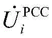
step 1: obtaining harmonic voltage and background harmonic voltage measured by a concerned bus and each harmonic current measured on a line corresponding to a suspicious harmonic source;
step 2: screening data segments with stable background harmonic waves in the data acquired in the step 1;
and step 3: calculating the harmonic transfer impedance between the suspicious harmonic source and the attention bus in sections for the data section obtained by screening in the step (2), and then performing average treatment on the section calculation result to be used as the harmonic transfer impedance between each suspicious harmonic source and the attention bus;
and 4, step 4: and according to the harmonic transfer impedance between each suspicious harmonic source and the concerned bus, quantifying the harmonic responsibility of different harmonic sources on the concerned bus.
The invention further comprises the following preferred embodiments:
preferably, the step 2 of screening the data obtained in the step 1 for the data segment with stable background harmonics includes the following steps:
step 2.1: preprocessing the data acquired in the step 1;
step 2.2: carrying out harmonic source signal reconstruction on the data preprocessed in the step 2.1 to obtain harmonic voltage measured by the concerned bus
Harmonic current generated by suspected harmonic source i
Quickly varying component of
And
step 2.3: segmental computation
The comprehensive entropy of the (A) is averaged,to obtain
Average comprehensive entropy of H
m;
Step 2.4: according to
And evaluating the fluctuation degree of the background harmonic wave by the average comprehensive entropy, and screening to obtain a data section with stable background harmonic wave.
Preferably, in step 2.1, the transformation of equations (8) and (9) is performed on each signal:
in the formula: mean(s) and std(s) respectively represent the expectation and variance of the signal s;
H(s)→H(s)/H(sG) (9)
in the formula: sGIs a standard gaussian signal with zero mean and unit variance, h(s) represents the entropy of the signal s.
Preferably, in step 2.3, the comprehensive entropy calculation formula is:
in the formula: the subscripts "x" and "y" denote the real and imaginary parts of the signal s, respectively.
Preferably, in step 2.4, if
Standing in the data section, and then the data section is a data section with stable background harmonic waves; otherwise, the fluctuation degree of the background harmonic of the data segment is further evaluated by applying the formula (11):
when the formula (11) is satisfied, it is considered that
Is close to or less than
The data segment is a data segment with stable background harmonic, otherwise, the background harmonic of the data segment is unstable;
preferably, in step 3, for a data segment, the method for calculating the harmonic transfer impedance between each suspected harmonic source and the concerned bus bar is as follows:
step 3.1: constructing and solving a single-point responsibility quantization model of each suspicious harmonic source i to obtain harmonic current generated by the harmonic source i
Step 3.2: based on each obtained
Establishing a multi-source responsibility quantification blind source separation model and solving by a multi-source complex independent component method to obtain harmonic transfer impedance Z
X,i。
Preferably, in step 3.1, the single point responsibility quantization model of the suspected harmonic source i is:
wherein
And
respectively representing the harmonic voltage and current measured at the point of common connection;
and Z
u,iRespectively a system side harmonic current and a harmonic impedance; z
c,iIs the user side harmonic impedance;
solving a single point responsibility quantization model of the suspicious harmonic source i by a single point model CICA algorithm, namely an equation (3), and obtaining
Preferably, step 3.2 specifically comprises:
step 3.2.1: based on each obtained
Establishing a multi-source responsibility quantification blind source separation model:
step 3.2.2: solving the multi-source responsibility quantization blind source separation model by a multi-source complex independent component method to obtain:
in the formula: upper label "fast"represents the fast-varying component of each signal;
step 3.2.3: calculating the harmonic transfer impedance Z between the ith suspected harmonic source and the bus X of interestX,i:
In the formula:
representing the derived mixing matrix
Row i +1 and column i.
Preferably, in
step 4, by mixing
Is projected to
In the above, the harmonic responsibility of the suspected harmonic source i is:
in the formula:
and
respectively representing the harmonic voltage measured by the concerned bus X and the background harmonic voltage;
representing the harmonic current measured on the common connection line between the ith suspect harmonic source and the grid; z
X,iRepresenting the harmonic transfer impedance between a suspicious harmonic source i and a concerned bus X under a certain harmonic; n-1 represents the number of suspected harmonic sources.
The invention also discloses a harmonic responsibility quantification system of the harmonic responsibility quantification method under the influence of the multi-user interaction of the power system, and the system comprises the following components:
the data acquisition module is used for acquiring harmonic voltage and background harmonic voltage measured by the concerned bus and harmonic currents of each order measured on a line corresponding to the suspicious harmonic source;
the data segment screening module is used for screening the data segment with stable background harmonic waves in the data acquired by the data acquisition module;
the data processing module is used for calculating the harmonic transfer impedance between the suspicious harmonic source and the concerned bus in sections of the data sections obtained by screening of the data section screening module, and then performing average processing on the sectional calculation results to serve as the harmonic transfer impedance between each suspicious harmonic source and the concerned bus;
and the quantification module is used for quantifying the harmonic responsibility of different harmonic sources on the attention bus according to the harmonic transfer impedance between each suspicious harmonic source and the attention bus.
The beneficial effect that this application reached:
according to the method, the fluctuation intensity of the background harmonic wave is quantified by adopting the comprehensive entropy according to the central limit theorem. When the background harmonic wave fluctuates violently, the corresponding comprehensive entropy is larger; on the contrary, when the background harmonic wave is stable, the corresponding pair of comprehensive entropy indexes is small. Through the proposed comprehensive entropy screening mechanism, data sections with relatively stable background harmonics can be selected and used for calculation, so that the calculation error of each algorithm on harmonic responsibility quantification is greatly reduced. And then accurately identifying the leading harmonic source and guiding harmonic treatment.
Detailed Description
The present application is further described below with reference to the accompanying drawings. The following examples are only for illustrating the technical solutions of the present invention more clearly, and the protection scope of the present application is not limited thereby.
As shown in fig. 1, the harmonic responsibility quantification method under the influence of the multi-user interaction of the power system of the present invention includes steps 1-4:
step 1: obtaining harmonic voltage and background harmonic voltage measured by a concerned bus and each harmonic current measured on a line corresponding to a suspicious harmonic source;
step 2: screening the data segment with stable background harmonic in the data acquired in the step 1, comprising the following steps:
in the calculation process of the step 3 independent component method, in order to maintain the invariance of the mixing matrix a, the harmonic impedance should be constant. To ensure this, the entire measurement data is usually divided into several short segments. Since the corresponding harmonic impedance can be considered to be approximately constant in a relatively short time, the harmonic transfer impedance can be calculated separately from each piece of data, and the result can be averaged. Furthermore, the computational accuracy of the independent component method also depends on the stationary background harmonics. Large fluctuations in background harmonics can increase computational errors. Therefore, if the fluctuation degree of the background harmonic can be evaluated, the calculation accuracy can be improved by selecting the data segments with relatively stable background harmonics for calculation, and the data segments with larger background harmonic fluctuation can be eliminated. The difficulty with this approach is that background harmonics cannot be measured directly. In order to overcome the difficulty, the invention provides a screening mechanism based on comprehensive entropy.
According to the central limit theorem, the distribution of the signal x composed of a plurality of random signals tends to be gaussian. In addition, if signal x is dominated by only a few signals, its gaussian nature will be reduced. For example, the signal x is composed of 4 random real signals si(i ═ 1,2,3,4) and their amplitudes are 1. The number of samples per signal is 3000. Their distribution and gaussian are shown in fig. 4, where the gaussian of the signal s is evaluated by the entropy shown in equation (7), with the greater the entropy, the stronger the corresponding gaussian.
In the formula: m is the sample size of the signal s, p(s)m) Is the probability density function of s.
Step 2.1: because the standard Gaussian signal has the maximum entropy in all the equal variance random signals, in order to make the entropy of different signals comparable, the data obtained in the step 1 is preprocessed as follows;
the transformations of equations (8) and (9) are performed for each signal, i.e., the harmonic voltage on the side of the attention bus of step 1, the background harmonic voltage, the individual harmonic current.
In the formula: mean(s) and std(s) respectively represent the expectation and variance of the signal s;
H(s)→H(s)/H(sG) (9)
in the formula: sGIs a standard gaussian signal with zero mean and unit variance, h(s) represents the entropy of signal s;
as shown in fig. 4, with signal si(i ═ 1,2,3,4) the mixed signal x is closer to a gaussian distribution than to a gaussian distribution. Meanwhile, the entropy of the signal x is also the largest of the signals, which shows that the entropy can correctly reflect the gaussian of the signal. At the signal s4After increasing the amplitude by k times, the distribution and entropy of the signal x are shown in fig. 5. With increasing k, the signal x gradually changes from s4Leading to a decrease in the gaussian of x, with a corresponding decrease in entropy.
The above analysis can be applied to equation (5) to evaluate the degree of fluctuation of the background harmonic voltage. Since the gaussians of each complex signal in equation (5) can be reflected by the gaussians of its real and imaginary parts, the gaussians of the complex signals are evaluated using the comprehensive entropy defined by equation (10).
Step 2.2: carrying out harmonic source signal reconstruction on the data preprocessed in the step 2.1 to obtain harmonic voltage measured by the concerned bus
Harmonic current generated by suspected harmonic source i
Quickly varying component of
And
namely: taking the preprocessed data as input, calculating by a complex independent component method, and outputting
And
quickly varying component of
And
step 2.3: segmental computation
After the comprehensive entropy is averaged to obtain
Average comprehensive entropy of H
m;
The comprehensive entropy calculation formula is as follows:
in the formula: the subscripts "x" and "y" denote the real and imaginary parts of the signal s, respectively.
Step 2.4: according to
And evaluating the fluctuation degree of the background harmonic wave by the average comprehensive entropy, and screening to obtain a data section with stable background harmonic wave.
For a data segment, two possible scenarios are discussed below:
case (1) - — background harmonic fluctuations are large:
in this case, it is preferable that,
will be harmonic of the background
Is dominant, and, therefore,
is relatively low. At this time, with
The comparison of the stable data segments is carried out,
is close to the comprehensive entropy of
And the value of entropy is small.
Case (2) - - -background harmonic stabilization:
in this case, it is preferable that,
typically with a higher gaussianity. However, if one of the harmonic current signals
In this data segment the fluctuation is large,
will be covered
And (4) leading. Thus, is obtained by
Compared with the situation that is relatively stable,
tends to
And still small. However, the case (2) is still very different from the case (1). Generally, the background harmonic voltage is a combination of other harmonics in the grid. Thus, with current signals generated by a single non-linear user
In contrast, according to the central limit theorem,
is generally more gaussian. Therefore, the temperature of the molten metal is controlled,
is usually greater than
Thus, for
Relatively small data segments if
Significantly larger than the rest of the signal obtained by separation
The background harmonics are considered to fluctuate more. Otherwise, if
Near or less than one of
The background harmonics are stable. In general, when equation (11) holds, it can be said that
Is close to or less than
For all of the given pieces of data,
the overall entropy of the corresponding signal can be obtained from equation (10). The average H of these synthetic entropies is then calculated
m. If it is not
Standing in the data segment, its corresponding background harmonic is stable. Otherwise, the fluctuation degree of the background harmonic is further evaluated using equation (11).
And step 3: calculating the harmonic transfer impedance between the suspicious harmonic source and the attention bus in sections for the data section obtained by screening in the step (2), and then performing average treatment on the section calculation result to be used as the harmonic transfer impedance between each suspicious harmonic source and the attention bus;
for a data segment, the calculation method of the harmonic transfer impedance between each suspicious harmonic source and the concerned bus bar comprises the following steps:
step 3.1: constructing and solving a single-point responsibility quantization model of each suspicious harmonic source i to obtain harmonic current generated by the harmonic source i
Accurately estimating harmonic transfer impedance Z between each suspicious harmonic source and concerned bus
X,iIs the key for quantifying the harmonic responsibility of each harmonic source on the attention bus. To calculate Z
X,iFirstly, the harmonic current generated by each harmonic source i needs to be solved through a single-point model
The single point responsibility quantization model of the harmonic source i is shown in fig. 3, and can be obtained from fig. 3, and the single point responsibility quantization model of the suspected harmonic source i is as follows:
wherein
And
respectively representing the harmonic voltage and current measured at the point of common connection;
and Z
u,iRespectively a system side harmonic current and a harmonic impedance; z
c,iIs the user side harmonic impedance;
by means of median filtering techniques, one obtains
And
and considering them as approximately independent;
thus, the equation (3) can be solved by the single-point model CICA algorithm, and each can be obtained
Step 3.2: based on each obtained
Establishing a multi-source responsibility quantification blind source separation model and solving by a multi-source complex independent component method to obtain harmonic transfer impedance Z
X,i;
Step 3.2.1: based on each obtained
A multi-source responsibility quantification blind source separation model can be established:
step 3.2.2: due to the fact that
And each
The fast-changing component is still approximate to be independent, so the formula (4) is solved by a multi-source complex independent component method to obtain:
in the formula: upper label "fast"represents the fast-varying component of each signal;
signals separated by multi-source complex independent component method
Corresponding real source signal
But with uncertainty of scaling. The uncertainty of its scaling is determined by the unknown complex coefficient k
iTo characterize;
step 3.2.3: calculating the harmonic transfer impedance Z between the ith suspected harmonic source and the bus X of interestX,i:
In the formula:
representing the derived mixing matrix
Row i +1 and column i.
Harmonic transfer impedance based on calculation
And equation (4) for reconstructing a reconstructed complex coefficient k not including an unknown complex coefficient
iOf the mixing matrix
Thereby resolving the scaling uncertainty of the separated signal Y.
Finally, based on the obtained
And
harmonic responsibilities of each suspect harmonic source on the bus of interest may be evaluated.
And 4, step 4: according to harmonic transfer impedance between each suspicious harmonic source and a concerned bus, harmonic responsibility of different harmonic sources on the concerned bus is quantized, specifically:
at h-th harmonic, the harmonic responsibility of different harmonic sources on the bus of interest can be described by the projection of the harmonic voltage generated on the bus of interest on the measured harmonic voltage when each harmonic source acts alone, as shown in fig. 2 and equation (1).
In the formula:
and
respectively represent offInjecting harmonic voltage measured by a bus X and background harmonic voltage;
representing the harmonic current measured on the common connection line between the ith suspect harmonic source and the grid; z
X,iRepresenting the harmonic transfer impedance between a suspicious harmonic source i and a concerned bus X under a certain harmonic; n-1 represents the number of suspected harmonic sources.
By mixing
Is projected to
The harmonic responsibility of the harmonic source i can be obtained as
As can be seen from equations (1) and (2), accurate calculation of the harmonic transfer impedance between each suspected harmonic source and the bus of interest is a key to quantifying the harmonic responsibilities.
The invention discloses a harmonic wave responsibility quantification system under the influence of multi-user interaction of a power system, which comprises:
the data acquisition module is used for acquiring harmonic voltage and background harmonic voltage measured by the concerned bus and harmonic currents of each order measured on a line corresponding to the suspicious harmonic source;
the data segment screening module is used for screening the data segment with stable background harmonic waves in the data acquired by the data acquisition module;
the data processing module is used for calculating the harmonic transfer impedance between the suspicious harmonic source and the concerned bus in sections of the data sections obtained by screening of the data section screening module, and then performing average processing on the sectional calculation results to serve as the harmonic transfer impedance between each suspicious harmonic source and the concerned bus;
and the quantification module is used for quantifying the harmonic responsibility of different harmonic sources on the attention bus according to the harmonic transfer impedance between each suspicious harmonic source and the attention bus.
For analysis using an IEEE-14 node system as an example, the suspected harmonic source and the bus of interest are shown in FIG. 6. The voltage of a certain harmonic wave measured at the bus line of interest and the current of each harmonic wave measured on the line corresponding to the suspected harmonic wave source are shown in fig. 7.
The harmonic impedance of the system side is Z according to the parameters of the IEEE-14 node systemu,A0.1747+0.7313jp.u. and Zu,BU. 0.2708+1.0004jp. And setting the user side harmonic impedance to Zc,A0.5+2jp.u. and Z c,B2+11jp. During the whole simulation process, Zu,A,Zu,B,Zc,AAnd Zc,BAre unknown and need to be solved. The above impedance values are only used as a reference for analyzing the calculation error.
By setting up
The influence of background harmonics on the calculation accuracy can be analyzed. As the coefficient k increases, the background harmonics become more and more unstable. The calculation error of the result obtained by the conventional independent component method and the independent component method introduced with the comprehensive entropy screening mechanism is shown in fig. 8. It can be seen that the calculation error of the conventional independent component method increases rapidly as the background harmonic increases. In contrast, the independent component method with the introduced comprehensive entropy screening mechanism has higher calculation result precision and meets the engineering requirements. Therefore, the comprehensive entropy screening mechanism has stronger capability of resisting background harmonic waves. Further, the harmonic responsibility of each harmonic source can be quantified according to the obtained harmonic impedance.
In conclusion, the method comprises the improvement of a multi-harmonic source independent component method and background harmonic stable data segment screening based on the maximum comprehensive entropy:
1) independent component method of multiple harmonic sources
And reconstructing the source signals by adopting a multi-source independent component method in a blind source separation theory under the condition that each harmonic source signal is unknown. And extracting the fast-changing component of the signal by a median filtering technology. The fast-varying components of the source signals are approximately independent, so that an application basis is provided for an independent component method. Further, based on the reconstructed source signals, harmonic transfer impedances between the suspected harmonic sources and the bus of interest are solved, and harmonic responsibilities are quantified. The existing independent component method has higher calculation precision under the condition of stable background harmonic waves, and can lay a foundation for further making a maximum comprehensive entropy screening model based on each reconstructed source signal.
2) Maximum comprehensive entropy screening
Based on the central limit theorem, the linear combination of a large number of independent random signals more approaches a gaussian distribution. When the background harmonic wave is stable, the fluctuation quantity of the voltage of the common connection point is generated by the combined action of all the harmonic wave sources, so that the Gaussian property is high. When the background harmonic wave fluctuates sharply, the fluctuation amount of the voltage of the common connection point will be dominated by the background harmonic wave, and the polarity thereof will be reduced. Theoretically, gaussian can be measured by entropy the stronger the gaussian, the larger the entropy. Therefore, the stability of the background harmonic wave can be quantified through the maximum comprehensive entropy screening model. By screening data segments with stable background harmonics, the harmonic responsibilities can be quantified more accurately.
The present applicant has described and illustrated embodiments of the present invention in detail with reference to the accompanying drawings, but it should be understood by those skilled in the art that the above embodiments are merely preferred embodiments of the present invention, and the detailed description is only for the purpose of helping the reader to better understand the spirit of the present invention, and not for limiting the scope of the present invention, and on the contrary, any improvement or modification made based on the spirit of the present invention should fall within the scope of the present invention.