CN112780828B - A composite high-speed intake and exhaust valve - Google Patents
A composite high-speed intake and exhaust valve Download PDFInfo
- Publication number
- CN112780828B CN112780828B CN202110068721.6A CN202110068721A CN112780828B CN 112780828 B CN112780828 B CN 112780828B CN 202110068721 A CN202110068721 A CN 202110068721A CN 112780828 B CN112780828 B CN 112780828B
- Authority
- CN
- China
- Prior art keywords
- cover
- floating body
- valve
- hole
- floating
- Prior art date
- Legal status (The legal status is an assumption and is not a legal conclusion. Google has not performed a legal analysis and makes no representation as to the accuracy of the status listed.)
- Active
Links
- 239000002131 composite material Substances 0.000 title claims description 15
- 238000007789 sealing Methods 0.000 claims abstract description 24
- 230000003068 static effect Effects 0.000 claims description 10
- XLYOFNOQVPJJNP-UHFFFAOYSA-N water Substances O XLYOFNOQVPJJNP-UHFFFAOYSA-N 0.000 description 25
- 230000005484 gravity Effects 0.000 description 6
- 238000010586 diagram Methods 0.000 description 5
- 230000009286 beneficial effect Effects 0.000 description 3
- 230000000694 effects Effects 0.000 description 3
- 230000003139 buffering effect Effects 0.000 description 2
- 238000000034 method Methods 0.000 description 2
- 230000001681 protective effect Effects 0.000 description 2
- 238000005452 bending Methods 0.000 description 1
- 238000000926 separation method Methods 0.000 description 1
Images


Classifications
-
- F—MECHANICAL ENGINEERING; LIGHTING; HEATING; WEAPONS; BLASTING
- F16—ENGINEERING ELEMENTS AND UNITS; GENERAL MEASURES FOR PRODUCING AND MAINTAINING EFFECTIVE FUNCTIONING OF MACHINES OR INSTALLATIONS; THERMAL INSULATION IN GENERAL
- F16K—VALVES; TAPS; COCKS; ACTUATING-FLOATS; DEVICES FOR VENTING OR AERATING
- F16K31/00—Actuating devices; Operating means; Releasing devices
- F16K31/12—Actuating devices; Operating means; Releasing devices actuated by fluid
- F16K31/18—Actuating devices; Operating means; Releasing devices actuated by fluid actuated by a float
- F16K31/20—Actuating devices; Operating means; Releasing devices actuated by fluid actuated by a float actuating a lift valve
-
- F—MECHANICAL ENGINEERING; LIGHTING; HEATING; WEAPONS; BLASTING
- F16—ENGINEERING ELEMENTS AND UNITS; GENERAL MEASURES FOR PRODUCING AND MAINTAINING EFFECTIVE FUNCTIONING OF MACHINES OR INSTALLATIONS; THERMAL INSULATION IN GENERAL
- F16K—VALVES; TAPS; COCKS; ACTUATING-FLOATS; DEVICES FOR VENTING OR AERATING
- F16K1/00—Lift valves or globe valves, i.e. cut-off apparatus with closure members having at least a component of their opening and closing motion perpendicular to the closing faces
- F16K1/32—Details
- F16K1/34—Cutting-off parts, e.g. valve members, seats
- F16K1/36—Valve members
-
- F—MECHANICAL ENGINEERING; LIGHTING; HEATING; WEAPONS; BLASTING
- F16—ENGINEERING ELEMENTS AND UNITS; GENERAL MEASURES FOR PRODUCING AND MAINTAINING EFFECTIVE FUNCTIONING OF MACHINES OR INSTALLATIONS; THERMAL INSULATION IN GENERAL
- F16K—VALVES; TAPS; COCKS; ACTUATING-FLOATS; DEVICES FOR VENTING OR AERATING
- F16K1/00—Lift valves or globe valves, i.e. cut-off apparatus with closure members having at least a component of their opening and closing motion perpendicular to the closing faces
- F16K1/32—Details
- F16K1/34—Cutting-off parts, e.g. valve members, seats
- F16K1/46—Attachment of sealing rings
-
- F—MECHANICAL ENGINEERING; LIGHTING; HEATING; WEAPONS; BLASTING
- F16—ENGINEERING ELEMENTS AND UNITS; GENERAL MEASURES FOR PRODUCING AND MAINTAINING EFFECTIVE FUNCTIONING OF MACHINES OR INSTALLATIONS; THERMAL INSULATION IN GENERAL
- F16K—VALVES; TAPS; COCKS; ACTUATING-FLOATS; DEVICES FOR VENTING OR AERATING
- F16K33/00—Floats for actuation of valves or other apparatus
-
- F—MECHANICAL ENGINEERING; LIGHTING; HEATING; WEAPONS; BLASTING
- F16—ENGINEERING ELEMENTS AND UNITS; GENERAL MEASURES FOR PRODUCING AND MAINTAINING EFFECTIVE FUNCTIONING OF MACHINES OR INSTALLATIONS; THERMAL INSULATION IN GENERAL
- F16K—VALVES; TAPS; COCKS; ACTUATING-FLOATS; DEVICES FOR VENTING OR AERATING
- F16K47/00—Means in valves for absorbing fluid energy
Landscapes
- Engineering & Computer Science (AREA)
- General Engineering & Computer Science (AREA)
- Mechanical Engineering (AREA)
- Self-Closing Valves And Venting Or Aerating Valves (AREA)
Abstract
Description
技术领域technical field
本发明涉及一种复合式高速进排气阀。The invention relates to a composite high-speed intake and exhaust valve.
背景技术Background technique
复合式高速进排气阀是一种供排水管道专用的进排气控制装置,广泛应用于各类水厂、各类给水领域的管网系统。由于进排气阀往往是安装在管道系统中较高的位置,其目的是利于进气和排气,当管道产生大量空气时,空气会不断的往高处流动,进排气阀正好安装在管道高处,且处于打开状态,大量空气会从管道吹进进排气阀底部,经过阀体内腔后从进排气阀的排气口排出,与外面大气压连通,当管道内形成负压时,由于外面大气压的压强大于管内气压,使得进排气阀的排气口打开进气,从而平衡管内与外面大气压,以免管道由于负压发生失稳破坏,同时,管道放空时,能自动大量的进气,使放水加快,缩短停水时间。The composite high-speed intake and exhaust valve is a special intake and exhaust control device for water supply and drainage pipelines, which is widely used in various water plants and pipeline network systems in various water supply fields. Since the intake and exhaust valves are often installed at higher positions in the pipeline system, their purpose is to facilitate intake and exhaust. When a large amount of air is generated in the pipeline, the air will continue to flow to the top, and the intake and exhaust valves are just installed in the When the pipeline is high and in the open state, a large amount of air will be blown into the bottom of the intake and exhaust valve from the pipeline, and then discharged from the exhaust port of the intake and exhaust valve after passing through the inner cavity of the valve body, and communicated with the outside atmospheric pressure. When negative pressure is formed in the pipeline , Since the pressure of the outside atmospheric pressure is stronger than the pressure inside the pipe, the exhaust port of the intake and exhaust valve opens the intake air, thereby balancing the atmospheric pressure inside the pipe and the outside, so as to avoid the instability and damage of the pipeline due to negative pressure. At the same time, when the pipeline is emptied, it can automatically Intake air to speed up the water release and shorten the water outage time.
但是该种结构的进排气阀存在着一些问题,当开关阀开启时,管内大量空气涌入到进排气阀内,浮球容易被其吹气,同时吹气的浮球撞击升降罩,造成排气口的关闭,当其压力过大更会损坏升降罩,导致阀门的密封性下降,易造成泄漏,并且排气过程中压强的变化,使得浮球处于上下浮动状态,浮球突然的下料,撞击阀体的内胆底部,降低浮球的使用寿命。However, there are some problems with the intake and exhaust valve of this structure. When the switch valve is opened, a large amount of air in the pipe flows into the intake and exhaust valve, and the floating ball is easily blown by it. At the same time, the blown floating ball hits the lift cover. Causes the exhaust port to be closed. When the pressure is too large, the lifting cover will be damaged, resulting in a decrease in the sealing of the valve, which is easy to cause leakage, and the pressure change during the exhaust process makes the float float up and down, and the float suddenly floats. Unloading, hitting the bottom of the inner tank of the valve body, reducing the service life of the float.
发明内容SUMMARY OF THE INVENTION
因此,针对上述的问题,本发明提供一种复合式高速进排气阀,它主要解决了现有技术中复合式高速进排气阀的耐用性差的问题。Therefore, in view of the above problems, the present invention provides a composite high-speed intake and exhaust valve, which mainly solves the problem of poor durability of the composite high-speed intake and exhaust valve in the prior art.
为实现上述目的,本发明采用了以下技术方案:To achieve the above object, the present invention has adopted the following technical solutions:
一种复合式高速进排气阀,包括阀体、设于阀体上的阀盖、设于阀盖上侧的排气罩,所述阀盖上设有进排气口,所述阀体上设有内腔以及与内腔连通的进口,所述内腔的中部设有浮体罩,通过浮体罩使得阀体与浮体罩之间形成流道,所述浮体罩的底部和上部分别设有连通浮体罩内部与流道的第一通孔和第二通孔,所述浮体罩内设有浮体和升降罩,所述升降罩分布于浮体的上侧,且其中部设有第三通孔,所述浮体的上部设有阀杆,该阀杆穿过第三通孔与排气罩连接,所述阀杆与第三通孔间隙配合,所述阀杆上设有密封圈,当浮体处于静止状态,升降罩与进排气口分离,使得流道与进排气口连通,当浮体处于漂浮状态,升降罩堵住进排气口,且,密封圈堵住第三通孔,所述浮体包括浮球以及设于浮球下部起到浮球的缓冲和平衡浮球浮力的连接部件。A composite high-speed intake and exhaust valve, comprising a valve body, a valve cover arranged on the valve body, and an exhaust cover arranged on the upper side of the valve cover, the valve cover is provided with an intake and exhaust port, and the valve body There is an inner cavity and an inlet communicating with the inner cavity, the middle part of the inner cavity is provided with a floating body cover, and a flow channel is formed between the valve body and the floating body cover through the floating body cover, and the bottom and the upper part of the floating body cover are respectively provided with A first through hole and a second through hole connecting the inside of the floating body cover with the flow channel, the floating body cover is provided with a floating body and a lifting cover, the lifting cover is distributed on the upper side of the floating body, and a third through hole is arranged in the middle , the upper part of the floating body is provided with a valve stem, the valve stem is connected with the exhaust hood through the third through hole, the valve stem is clearance fit with the third through hole, and the valve stem is provided with a sealing ring, when the floating body In a static state, the lift cover is separated from the intake and exhaust ports, so that the flow channel is connected to the intake and exhaust ports. When the floating body is in a floating state, the lift cover blocks the intake and exhaust ports, and the sealing ring blocks the third through hole, so The floating body includes a floating ball and a connecting part arranged at the lower part of the floating ball to buffer the floating ball and balance the buoyancy of the floating ball.
进一步的,所述连接部件包括底部、由底部周沿向上延伸设置的侧部、与侧部上端一体连接的连接部,所述连接部的上端与浮球的外表面连接,所述连接部上设有第四通孔。Further, the connecting member includes a bottom, a side portion extending upward from the circumference of the bottom, and a connecting portion integrally connected with the upper end of the side portion, the upper end of the connecting portion is connected with the outer surface of the floating ball, and the connecting portion is on the upper end of the floating ball. A fourth through hole is provided.
进一步的,环绕所述侧部的中部设有折叠线,使得侧部的中部内凹形成层叠结构,所述侧部的外表面上位于折叠线处设有橡筋。Further, a folding line is provided around the middle portion of the side portion, so that the middle portion of the side portion is concave to form a laminated structure, and an elastic band is provided on the outer surface of the side portion at the folding line.
进一步的,所述升降罩具有弹性,所述升降罩沿其径向方向依次包括呈弧形结构的第一部、第二部和第三部,所述第一部的曲率半径大于第三部的曲率半径,所述第三部的曲率半径大于第二部的曲率半径,所述第三通孔设于第一部上,当浮体处于漂浮状态,第三部的上表面抵靠于进排气口的周沿。Further, the lift cover has elasticity, and the lift cover sequentially includes a first part, a second part and a third part in an arc structure along the radial direction thereof, and the curvature radius of the first part is larger than that of the third part The radius of curvature of the third part is larger than the radius of curvature of the second part, the third through hole is set on the first part, when the floating body is in a floating state, the upper surface of the third part abuts the inlet and outlet The perimeter of the vent.
进一步的,所述第三部的上表面上沿其径向方向设有若干个阶梯结构。Further, the upper surface of the third part is provided with several stepped structures along its radial direction.
进一步的,所述阀盖上位于进排气口的内沿嵌设有密封块,当浮体处于漂浮状态,第三部的上表面的阶梯结构卡置于密封块上。Further, a sealing block is embedded on the inner edge of the valve cover at the intake and exhaust ports. When the floating body is in a floating state, the stepped structure on the upper surface of the third part is clamped on the sealing block.
进一步的,环绕所述浮球的中部平行凹设有至少两条凹槽。Further, at least two grooves are concave in parallel around the middle of the floating ball.
进一步的,所述浮体罩的侧壁上设有第五通孔,当浮体处于静止状态,第五通孔分布于凹槽的下侧。Further, the side wall of the floating body cover is provided with fifth through holes. When the floating body is in a static state, the fifth through holes are distributed on the lower side of the groove.
进一步的,所述阀体与阀盖之间设有呈环形结构的密封垫,当浮体处于漂浮状态,第三部的上表面的阶梯结构卡置于密封垫的内沿上。Further, a ring-shaped sealing gasket is arranged between the valve body and the valve cover. When the floating body is in a floating state, the stepped structure on the upper surface of the third part is clamped on the inner edge of the sealing gasket.
进一步的,所述浮体罩上且位于第一通孔的周沿设有缓冲垫。Further, a buffer pad is provided on the floating body cover and at the periphery of the first through hole.
通过采用前述技术方案,本发明的有益效果是:本复合式高速进排气阀,当浮体处于静止状态时,在浮体的自身重力作用下处于浮体罩的底部,从而带动升降罩与进排气口分离,开关阀开启后,管道内储存的大量气体,通过阀体内的流道、进排气口排出,该进排气口的孔径大,排气量大,能够快速的排出气体,并且通过浮球中部设置的凹槽与浮体罩上设置的通孔配合,使得气流速度较快进入阀体内时,其一部分气体通过第一通孔进入到浮体罩内,另一部分通过流道流动,并通过浮体罩侧壁上的第五通孔和上部的第二通孔进入到浮体罩内,形成径向的作用力,并在浮球上的凹槽作用下,使得浮体处于稳定上升,并处于悬浮平衡状态,防止浮体在气流不稳定状态下,上下浮动撞击浮体罩6和升降罩,起到保护的作用,并且使得进排气阀的工作稳定,提高耐用性;当阀体内的气体排出后,水进入到阀体内,并沿气体流动路径流动,浮体罩上的第五通孔和第二通孔与浮球上的凹槽配合,使得浮体平稳上升,并在浮球的浮力下,使得升降罩堵住进排气口,且,密封圈堵住第三通孔,实现进排气阀的关闭,在水填入到浮体罩内时,连接部件的连接部上设置的第四通孔,使得水填入到连接部件的内腔内,能够进一步提升浮体的运行稳定性,将其水流对浮体的浮动影响,并且在水中析出的空气,使得浮体下降时,运行稳定,此时,第三通孔与阀盖上的密封圈分离,实现第三通孔的开启,能够排出较少的气体,实现二段开启,当开关阀关闭后,连接部内的水能够使得浮球紧贴附于水平面下降,提高浮体运行稳定性,并且连接部在橡筋作用下,使得连接部紧缩,连接部内的水通过第四通孔向外喷出,使得连接部与浮体罩底部撞击中,起到较好的缓冲作用,通过连接部件内残余的水能够提高浮体的重力,极大降低气流导致浮体的浮动,有利于进排气口的排气。By adopting the aforementioned technical solutions, the beneficial effects of the present invention are: when the floating body is in a static state, the composite high-speed air intake and exhaust valve is located at the bottom of the floating body cover under the action of the floating body's own gravity, thereby driving the lifting cover and the air intake and exhaust. The port is separated, and after the switch valve is opened, a large amount of gas stored in the pipeline is discharged through the flow channel and the inlet and exhaust ports in the valve body. The groove set in the middle of the floating ball cooperates with the through hole set on the floating body cover, so that when the airflow speed enters the valve body at a relatively high speed, a part of the gas enters the floating body cover through the first through hole, and the other part flows through the flow channel and passes through the valve body. The fifth through hole on the side wall of the floating body cover and the second through hole on the upper part enter the floating body cover, forming a radial force, and under the action of the groove on the floating ball, the floating body is in a stable rise and is suspended Balanced state, preventing the floating body from floating up and down against the
附图说明Description of drawings
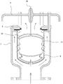
图1是本发明实施例中浮体处于静止状态的结构示意图;1 is a schematic structural diagram of a floating body in a static state in an embodiment of the present invention;
图2是本发明实施例中浮体处于漂浮状态的结构示意图;2 is a schematic structural diagram of a floating body in a floating state according to an embodiment of the present invention;
图3是图2中A处的局部放大图;Fig. 3 is the partial enlarged view of A place in Fig. 2;
图4是本发明实施例中升降罩的结构示意图;4 is a schematic structural diagram of a lift cover in an embodiment of the present invention;
图5是本发明实施例中浮体处于静止状态下气流的流动示意图;Fig. 5 is the flow schematic diagram of the airflow when the floating body is in a static state in the embodiment of the present invention;
图6是本发明实施例中浮体处于漂浮状态下气流的流动示意图。FIG. 6 is a schematic diagram of the flow of airflow when the floating body is in a floating state according to an embodiment of the present invention.
具体实施方式Detailed ways
现结合附图和具体实施方式对本发明进一步说明。The present invention will now be further described with reference to the accompanying drawings and specific embodiments.
本发明实施例为:The embodiment of the present invention is:
参考图1与图2所示,一种复合式高速进排气阀,包括阀体1、设于阀体1上的阀盖2、设于阀盖2上侧的排气罩3,所述阀盖2上设有进排气口4,所述进排气口4的直径尺寸与阀盖2的外直径尺寸的比值为4:5,所述阀体1上设有内腔以及与内腔连通的进口5,所述内腔的中部设有浮体罩6,通过浮体罩6使得阀体1与浮体罩6之间形成流道7,所述浮体罩6的底部、侧壁和上部分别设有连通浮体罩6内部与流道7的第一通孔8、第五通孔9和第二通孔10,所述浮体罩6内设有浮体11和升降罩12,所述升降罩12的周沿向下弯折延伸有延伸部20,该延伸部20抵靠与浮体11上,所述升降罩12分布于浮体11的上侧,且其中部设有第三通孔13,所述浮体11的上部设有阀杆30,该阀杆30穿过第三通孔13与排气罩3连接,所述阀杆30与第三通孔13间隙配合,所述阀杆30上设有密封圈15,当浮体11处于静止状态,升降罩12与进排气口4分离,使得流道7与进排气口4连通,当浮体11处于漂浮状态,升降罩12堵住进排气口4,且,密封圈15堵住第三通孔13,所述浮体11包括浮球111以及设于浮球111下部起到浮球111的缓冲和平衡浮球111浮力的连接部件112,具体的,所述连接部件112包括底部21、由底部21周沿向上延伸设置的侧部22、与侧部22上端一体连接的连接部23,所述连接部23的上端与浮球111的外表面连接,所述连接部23上设有第四通孔24,环绕所述侧部22的中部设有折叠线25,使得侧部22的中部内凹形成层叠结构,所述侧部22的外表面上位于折叠线25处设有橡筋26,环绕所述浮球111的中部平行凹设有两条凹槽14,并且,当浮体11处于静止状态,第五通孔9分布于凹槽14的下侧,所述浮体罩6上且位于第一通孔8的周沿设有缓冲垫16。Referring to FIG. 1 and FIG. 2 , a composite high-speed intake and exhaust valve includes a
参考图5与图6所示,当浮体11处于静止状态时,在浮体11的自身重力作用下处于浮体罩6的底部,从而带动升降罩12与进排气口4分离,开关阀开启后,管道内储存的大量气体,通过阀体1内的流道7、进排气口4排出,该进排气口4的孔径大,排气量大,能够快速的排出气体,并且通过浮球111中部设置的凹槽14与浮体罩6上设置的通孔配合,使得气流速度较快进入阀体1内时,其一部分气体通过第一通孔8进入到浮体罩6内,另一部分通过流道7流动,并通过浮体罩6侧壁上的第五通孔9和上部的第二通孔10进入到浮体罩6内,形成径向的作用力,并在浮球111上的凹槽14作用下,使得浮体11处于稳定上升,并处于悬浮平衡状态,防止浮体11在气流不稳定状态下,上下浮动撞击浮体罩6和升降罩12,起到保护的作用,并且使得进排气阀的工作稳定,提高耐用性;当阀体1内的气体排出后,水进入到阀体1内,并沿气体流动路径流动,浮体罩6上的第五通孔9和第二通孔10与浮球111上的凹槽14配合,使得浮体11平稳上升,并在浮球111的浮力下,使得升降罩12堵住进排气口4,且,密封圈15堵住第三通孔13,实现进排气阀的关闭,在水填入到浮体罩6内时,连接部件12的连接部13上设置的第四通孔24,使得水填入到连接部件12的内腔内,能够进一步提升浮体11的运行稳定性,将其水流对浮体的浮动影响,并且在水中析出的空气,使得浮体11下降时,运行稳定,此时,第三通孔13与阀盖2上的密封圈15分离,实现第三通孔13的开启,能够排出较少的气体,实现二段开启,当开关阀关闭后,连接部23内的水能够使得浮球111紧贴附于水平面下降,提高浮体11运行稳定性,并且连接部23在橡筋26作用下,使得连接部23紧缩,连接部23内的水通过第四通孔24向外喷出,使得连接部23与浮体罩6底部撞击中,起到较好的缓冲作用,通过连接部件12内残余的水能够提高浮体11的重力,极大降低气流导致浮体的浮动,有利于进排气口4的排气。Referring to FIG. 5 and FIG. 6 , when the floating
参考图2、图3与图4所示,本实施例中,所述阀体1与阀盖2之间设有呈环形结构的密封垫31,所述阀盖2上位于进排气口4的内沿嵌设有密封块32,所述升降罩12具有弹性,所述升降罩12沿其径向方向依次包括呈弧形结构的第一部121、第二部122和第三部123,所述第一部121的曲率半径大于第三部123的曲率半径,所述第三部123的曲率半径大于第二部122的曲率半径,所述第三通孔13设于第一部121上,所述第三部123的上表面上沿其径向方向设有三个阶梯结构33,当浮体11处于漂浮状态,第三部123的上表面的阶梯结构33卡置于密封块32和密封垫31的内沿上。Referring to FIG. 2 , FIG. 3 and FIG. 4 , in this embodiment, a sealing
在浮体11在浮力作用下,带动升降罩12向上浮动,并且将升降罩12向上挤压阀盖2的进排气口4,通过设置第一部121、第二部122和第三部123的曲率半径不同,使得三者的弯折角度形成差异,在浮力作用下,第三部123的上表面的阶梯结构33分别卡置于密封块32和密封垫31的内沿上,形成双重密封,密封效果好,防止水外渗,提高进排气阀的使用效果,并且其卡置力,能够延迟升降盖与进排气口4的分离,使得第三通孔13排出较少气体,避免进排气口4与升降罩12在水流不稳定的状态下分离,从而使得水外溢,同时浮体11上设置的连接部件12内填充的水提高浮体的重力,在该重力作用下,使得升降罩12与进排气口4分离,大大提高了进排气阀的使用效果。Under the action of buoyancy, the floating
尽管结合优选实施方案具体展示和介绍了本发明,但所属领域的技术人员应该明白,在不脱离所附权利要求书所限定的本发明的精神和范围内,在形式上和细节上可以对本发明做出各种变化,均为本发明的保护范围。Although the present invention has been particularly shown and described in connection with preferred embodiments, it will be understood by those skilled in the art that changes in form and detail may be made to the present invention without departing from the spirit and scope of the invention as defined by the appended claims. Various changes are made within the protection scope of the present invention.
Claims (7)
Priority Applications (1)
| Application Number | Priority Date | Filing Date | Title |
|---|---|---|---|
| CN202110068721.6A CN112780828B (en) | 2021-01-19 | 2021-01-19 | A composite high-speed intake and exhaust valve |
Applications Claiming Priority (1)
| Application Number | Priority Date | Filing Date | Title |
|---|---|---|---|
| CN202110068721.6A CN112780828B (en) | 2021-01-19 | 2021-01-19 | A composite high-speed intake and exhaust valve |
Publications (2)
| Publication Number | Publication Date |
|---|---|
| CN112780828A CN112780828A (en) | 2021-05-11 |
| CN112780828B true CN112780828B (en) | 2022-05-06 |
Family
ID=75757634
Family Applications (1)
| Application Number | Title | Priority Date | Filing Date |
|---|---|---|---|
| CN202110068721.6A Active CN112780828B (en) | 2021-01-19 | 2021-01-19 | A composite high-speed intake and exhaust valve |
Country Status (1)
| Country | Link |
|---|---|
| CN (1) | CN112780828B (en) |
Families Citing this family (1)
| Publication number | Priority date | Publication date | Assignee | Title |
|---|---|---|---|---|
| CN120251776A (en) * | 2025-06-09 | 2025-07-04 | 沪航科技集团有限公司 | Intelligent exhaust valve |
Citations (1)
| Publication number | Priority date | Publication date | Assignee | Title |
|---|---|---|---|---|
| CN111442097A (en) * | 2020-04-13 | 2020-07-24 | 广东联塑阀门有限公司 | Combined type high-speed air inlet and outlet valve |
Family Cites Families (6)
| Publication number | Priority date | Publication date | Assignee | Title |
|---|---|---|---|---|
| GB825043A (en) * | 1955-02-07 | 1959-12-09 | George Henry Osborne | Improvements in or relating to valve devices for controlling liquid flow |
| JP4497604B2 (en) * | 1999-11-08 | 2010-07-07 | 旭有機材工業株式会社 | Air valve |
| JP2003232494A (en) * | 2002-02-08 | 2003-08-22 | Aisan Ind Co Ltd | trap |
| CN207599238U (en) * | 2017-12-04 | 2018-07-10 | 泉州市沪航阀门制造有限公司 | A kind of air bleeding valve of band buffering filter device |
| CN210716015U (en) * | 2019-09-30 | 2020-06-09 | 沪航科技集团有限公司 | Exhaust valve |
| CN211203028U (en) * | 2019-11-28 | 2020-08-07 | 济南迈克阀门科技有限公司 | Combined type air inlet and outlet valve |
-
2021
- 2021-01-19 CN CN202110068721.6A patent/CN112780828B/en active Active
Patent Citations (1)
| Publication number | Priority date | Publication date | Assignee | Title |
|---|---|---|---|---|
| CN111442097A (en) * | 2020-04-13 | 2020-07-24 | 广东联塑阀门有限公司 | Combined type high-speed air inlet and outlet valve |
Also Published As
| Publication number | Publication date |
|---|---|
| CN112780828A (en) | 2021-05-11 |
Similar Documents
| Publication | Publication Date | Title |
|---|---|---|
| CN104913111B (en) | Water hammer-resistant method for exhausting during water hammer-resistant air valve and pipeline use | |
| CN112780828B (en) | A composite high-speed intake and exhaust valve | |
| CN103591368A (en) | Anti-return-air automatic exhaust valve | |
| CN111734828A (en) | Anti-sewage leakage type sewage air valve | |
| CN114877078A (en) | Negative pressure angle seat valve for vacuum sewage pipeline | |
| CN202561178U (en) | Exhaust valve | |
| CN202691192U (en) | Combined type exhaust valve | |
| CN111442097A (en) | Combined type high-speed air inlet and outlet valve | |
| CN107166058A (en) | A kind of three hole air bleeding valves | |
| CN207145661U (en) | A kind of three hole air bleeding valves | |
| CN113047904A (en) | Positive and negative pressure automatic water drainage device | |
| CN107781468A (en) | A kind of ventilative check-valves | |
| CN207554932U (en) | Built-in ball-cock assembly | |
| CN106195414B (en) | A kind of composite exhaust valve with buffer unit | |
| CN204879015U (en) | Row of closing air valve group slowly | |
| CN207864688U (en) | Triple valve | |
| CN206874909U (en) | Pneumatic type saves water trap | |
| CN108612903A (en) | A kind of energy dissipating Slow Close air inlet and exhaust valve | |
| CN211501825U (en) | High Efficiency Exhaust Sewage Air Valve | |
| CN211423689U (en) | Quick exhaust valve for agricultural irrigation pipeline | |
| CN204901048U (en) | A elastic support structure for delaying close slowly close mechanism on air bleeding valve on | |
| CN204589942U (en) | A kind of ecological gate of Pneumatic floater of improvement | |
| CN104964118B (en) | A kind of composite exhaust valve | |
| CN220168723U (en) | Combined type air inlet and outlet valve | |
| CN205401839U (en) | Novel check valve |
Legal Events
| Date | Code | Title | Description |
|---|---|---|---|
| PB01 | Publication | ||
| PB01 | Publication | ||
| SE01 | Entry into force of request for substantive examination | ||
| SE01 | Entry into force of request for substantive examination | ||
| GR01 | Patent grant | ||
| GR01 | Patent grant | ||
| TR01 | Transfer of patent right | ||
| TR01 | Transfer of patent right |
Effective date of registration: 20221021 Address after: No. 59, Tinghua Road, Tinglin Town, Jinshan District, Shanghai, 201505 Patentee after: SHANGHAI HUHANG VALVES Co.,Ltd. Address before: No.11, Meiyu Road, Meiyu valve garden, Luncang, Nan'an City, Quanzhou City, Fujian Province, 362300 Patentee before: HUHANG TECHNOLOGY GROUP Co.,Ltd. |
|
| PE01 | Entry into force of the registration of the contract for pledge of patent right |
Denomination of invention: A composite high-speed intake and exhaust valve Effective date of registration: 20230810 Granted publication date: 20220506 Pledgee: Shanghai Rural Commercial Bank Co.,Ltd. Jinshan sub branch Pledgor: SHANGHAI HUHANG VALVES Co.,Ltd. Registration number: Y2023310000451 |
|
| PE01 | Entry into force of the registration of the contract for pledge of patent right | ||
| PC01 | Cancellation of the registration of the contract for pledge of patent right |
Granted publication date: 20220506 Pledgee: Shanghai Rural Commercial Bank Co.,Ltd. Jinshan sub branch Pledgor: SHANGHAI HUHANG VALVES Co.,Ltd. Registration number: Y2023310000451 |
|
| PC01 | Cancellation of the registration of the contract for pledge of patent right | ||
| TR01 | Transfer of patent right |
Effective date of registration: 20250414 Address after: No.11, Meiyu Road, Meiyu valve garden, Luncang, Nan'an City, Quanzhou City, Fujian Province, 362300 Patentee after: HUHANG TECHNOLOGY GROUP Co.,Ltd. Country or region after: China Address before: No. 59, Tinghua Road, Tinglin Town, Jinshan District, Shanghai, 201505 Patentee before: SHANGHAI HUHANG VALVES Co.,Ltd. Country or region before: China |
|
| TR01 | Transfer of patent right |