Drive-by-wire braking system with redundancy function
Technical Field
The invention relates to the field of automobile brakes, in particular to a brake-by-wire system with a redundancy function.
Background
The brake is an important part for vehicle safety, and the driving safety is directly influenced by the performance of the brake. At present, a hydraulic brake system is mainly adopted for a vehicle, and the problems of long brake pipeline, more valve elements, easy environmental pollution caused by brake fluid, easy generation of brake pipeline pressure fluctuation during ABS work and the like exist.
The brake-by-wire technology is a novel brake technology appearing in recent years, a brake and a brake pedal do not depend on mechanical or hydraulic connection, a part of or all brake pipelines are replaced by electric wires, and an electric control element is operated by a controller to control the magnitude of braking force, so that the stable and reliable brake control of an automobile is realized. At present, the brake-by-wire system mainly comprises an electronic hydraulic brake system (EHB) and an electronic mechanical brake system (EMB). The brake-by-wire system is beneficial to optimizing the braking performance of the whole vehicle, and can be conveniently integrated with other electronic control systems such as ABS, ASR, ESP and the like, so that the system has wide development space. Especially as a brake system for an unmanned vehicle, is considered to be better by those skilled in the art.
The electronic hydraulic brake system (EHB) is formed by transforming the traditional hydraulic brake system, the braking process is quicker and more stable, the braking safety and the comfort of an automobile are improved, but the electronic hydraulic brake system does not have all the advantages of a complete brake-by-wire system because a hydraulic component is reserved, and is generally regarded as an advanced product of an electronic mechanical brake system (EMB). The original hydraulic pipeline is reserved, and the technical problem of slow brake response caused by long hydraulic pipeline is still not solved. Meanwhile, the brake pipeline can be elastically deformed under the action of high-pressure brake oil, so that the pressure fluctuation of the brake oil in the brake pipeline is caused, and the accurate control of the vehicle brake is greatly influenced.
The technical scheme of the prior electronic mechanical brake system (EMB) is that a motor drives a mechanical mechanism to realize a braking process, so that the structure of the brake system is greatly simplified, and the brake is easier to arrange, assemble and overhaul. The existing electronic mechanical brake system mostly adopts a brake motor and a speed reducing mechanism or a force increasing mechanism as power sources, so that the overall structure size is larger. In the braking process, the braking motor is always in a locked-rotor state, so that the requirement on the performance of the braking motor is high. In order to ensure enough braking torque, the main technical scheme adopted at present is a motor acceleration and deceleration mechanism, but the deceleration mechanism can cause slow braking response and increase the braking distance of a vehicle. Meanwhile, the EMB also has the problem of brake failure caused by circuit and electronic product faults, and potential safety hazards are brought to driving.
Along with the popularization of new energy vehicles and intelligent vehicles, an electronic mechanical brake system is inevitably widely applied, the problems of motor performance indexes and high price caused by the fact that an EMB installation space and a brake motor are in a locked-rotor state for a long time are solved, the problem that a brake response is slow due to a speed reducing mechanism is solved, the problem of brake clearance is rapidly eliminated, and the problem of reliability of a line control actuator is solved urgently.
Disclosure of Invention
Aiming at the defects of the existing brake-by-wire system, the invention provides the brake-by-wire system with redundant functions, which can quickly eliminate brake clearance, shorten brake response time and has higher brake control precision and response frequency; even if the electromechanical braking system fails, the vehicle can still be braked by the conventional hydraulic braking system, and the reliability is high; the braking distance can be effectively shortened, and the driving safety of the vehicle is improved.
The invention is realized by the following technical measures:
a brake-by-wire system with redundant functions comprises a brake-by-wire, a brake pump shell, a liquid storage chamber, a first spring, a first piston assembly, a check ring, a rubber ring, a second spring, a second piston assembly, a brake pedal, an angle sensor and a controller which are in modular design;
the line control actuator comprises a brake disc, a left friction plate, a right friction plate, calipers, an electromagnetic coil, a cylinder body assembly, a brake pipeline, a hydraulic control unit, a brake piston, a magnetostrictive rod and a wheel speed sensor; the brake disc is connected with the axle bolt, the left friction plate and the right friction plate are respectively arranged on the left side and the right side of the brake disc, and the left friction plate and the right friction plate are respectively arranged in an adaptive groove on the caliper through back steel sheets on the left friction plate and the right friction plate so as to carry out rotation limiting; the calipers are fixedly arranged on a vehicle body; the electromagnetic coil is fixedly sleeved on the brake piston, and a certain gap is reserved between the left end and the right end of the electromagnetic coil and the calipers and the cylinder body assembly respectively; the left end of the brake piston is installed in a hole in the right side wall of the caliper in a matched mode, the magnetostrictive rod is installed in an inner hole of the brake piston, the length of the magnetostrictive rod is equal to the depth of the inner hole of the brake piston, and the left end faces of the brake piston and the magnetostrictive rod are in surface contact with the back steel sheet of the right friction plate; the right end of the brake piston is arranged in a cylinder body on the cylinder body assembly, and a sealing ring is arranged in an annular notch corresponding to the brake piston and the cylinder body and used for sealing brake fluid and resetting the brake piston after braking; the wheel speed sensor is fixedly arranged on a wheel;
the cylinder body assembly comprises a cylinder body, a bracket and an oil inlet nozzle; the oil inlet nozzle is arranged on the cylinder body and is used for being connected with the hydraulic control unit through a brake pipeline, the cylinder body is fixedly arranged at the end part of the support, and the support legs of the support are fixedly arranged on the calipers;
the hydraulic control unit comprises a spring one-way valve, an energy accumulator and a three-position three-way electromagnetic valve; the three-position three-way electromagnetic valve is in a normally closed state, namely the port P3, the port P1 and the port P2 are not communicated; the port P0 is connected with a pipeline of the port P1 through a spring one-way valve, and an energy accumulator is arranged on the pipeline and used for storing energy; the port P0 is directly connected with the port P2 through a pipeline; the port P3 is connected with an oil inlet nozzle on the cylinder body assembly through a brake pipeline; the port P0 is connected with an oil outlet pipeline of the brake pump shell;
the brake pump shell is fixedly arranged on the vehicle body, and the check ring is fixedly arranged on the wall of the inner cavity of the brake pump shell to divide the brake pump shell into a left cavity and a right cavity; the first spring and the first piston assembly are arranged in a left cavity of the brake pump shell, and the first spring is used for supporting the first piston assembly to reset; the ejector rod of the first piston assembly penetrates through the retainer ring to penetrate into the right cavity of the brake pump shell; the second piston assembly, the rubber ring and the second spring are arranged in a right cavity of the brake pump shell, and the rubber ring and the second spring are arranged between the second piston assembly and the retainer ring; a certain distance is reserved between the ejector rod of the first piston assembly and the second piston assembly; a mandril of the second piston assembly is hinged with the brake pedal; the brake pedal is hinged with the vehicle body, and an angle sensor is arranged at the hinged position; the left cavity of the brake pump shell is connected with a liquid storage chamber pipeline;
the electromagnetic coil, the angle sensor, the wheel speed sensor and the three-position three-way electromagnetic valve are all electrically connected with the controller; the controller collects signals of the angle sensor and the wheel speed sensor in real time to judge the operation state of a driver and the braking condition of a vehicle;
when the vehicle braking system works normally, a driver steps on a brake pedal, the brake pedal pushes the second piston assembly to move left, and the rubber ring and the second spring play a role in simulating the brake pedal and a role in resetting when braking is finished; when the stepping amplitude of the brake pedal is relatively large, the left movement of the second piston assembly can push the first piston assembly to move left, so that the brake oil can charge and build pressure for the energy accumulator through a port P0 and the spring check valve; because the three-position three-way electromagnetic valve is in a normally closed state, brake oil in the left cavity of the brake pump shell does not generate acting force on the brake piston;
the controller judges the emergency degree of the driver for stepping on the brake and the brake by acquiring the signals of the angle sensor in real time; the controller controls the three-position three-way electromagnetic valve to work, high-pressure brake oil in the energy accumulator flows into the cylinder body through a port P1, a port P3, a brake pipeline and an oil inlet nozzle, so that the brake piston is pushed to move left, the magnetostrictive rod is driven to move left when the brake piston moves left, and the left end faces of the brake piston and the magnetostrictive rod press the right friction plate to quickly eliminate a brake gap and preliminarily establish brake pressure; the controller controls the three-position three-way electromagnetic valve to work, the three-position three-way electromagnetic valve is in a normally closed state, at the moment, a cavity formed by the brake piston and the cylinder body is a closed cavity, and brake oil in the closed cavity plays a role of rigid support for the right end of the brake piston due to small compressibility of the brake oil; the controller judges the emergency degree of the driver stepping on the brake according to the signal of the angle sensor, judges the locking state of the wheel according to the signal of the wheel speed sensor to formulate a control strategy, changes the strength of a magnetic field by controlling the current of the electromagnetic coil, further accurately controls the extension length of the magnetostrictive rod, and further controls the left friction plate and the right friction plate to press the brake disc to generate the braking force; when braking is finished, the controller controls the three-position three-way electromagnetic valve to work, brake oil in a cavity formed by the brake piston and the cylinder body flows back to a left cavity of the brake pump shell through a port P3, a port P2 and a port P0, redundant oil flows back to the liquid storage chamber, and all parts are reset;
when the brake controller fails, a driver continuously steps on a brake pedal, the second piston assembly continuously moves leftwards to push the first piston assembly to continuously move leftwards, the controller controls the three-position three-way electromagnetic valve to work, brake oil in a left cavity of the brake pump shell flows into the cylinder body through the port P0, the port P2, the port P3, the brake pipeline and the oil inlet nozzle, the brake piston is further pushed to move leftwards to push the right friction plate to press the brake disc, and braking force is generated under the combined action of the left friction plate and the right friction plate to realize a braking redundancy function.
Further, the inner hole of the rubber ring is conical.
The invention has the beneficial effects that:
a wire control brake system with redundant functions adopts a magnetostrictive actuator as a power source of an electronic mechanical brake system, adopts an energy accumulator device to quickly eliminate brake clearance, shortens brake response time, and has higher brake control precision and response frequency; even if the electromechanical braking system fails, the vehicle can still be braked by the conventional hydraulic braking system, and the reliability is high; the braking distance can be effectively shortened, and the driving safety of the vehicle is improved.
After the technical scheme is adopted, compared with the prior art, the invention has the following beneficial effects:
1. the magnetostrictive actuator is used as a power source, a driving motor and a speed reducing mechanism in the prior art are eliminated, and the energy accumulator device is adopted to quickly eliminate the braking gap, so that the braking response speed is effectively improved, and the installation space is reduced.
2. The conventional hydraulic brake adopts an 'on-off' regulation mode of pressurization, pressure maintaining and pressure reduction when wheels are locked, and the hydraulic brake has the advantages of continuous adjustability and higher control precision.
3. The conventional hydraulic brake system is used as a redundant backup, so that the reliability of the brake is improved.
4. And a brake-by-wire mode is adopted, so that system integration with ABS, EBD and the like is facilitated, and higher control precision is achieved.
Drawings
The invention is further illustrated with reference to the following figures and examples.
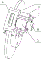
Fig. 1 is a front view of the present invention.
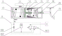
Fig. 2 is a schematic structural diagram of the present invention.
Fig. 3 is a partial structural schematic diagram of the present invention.
Fig. 4 is a partial structural schematic diagram of the present invention.
Fig. 5 is a partial structural schematic diagram of the present invention.
FIG. 6 is a schematic view of a caliper structure according to the present invention.
FIG. 7 is a schematic view of a cylinder assembly according to the present invention.
Fig. 8 is a cross-sectional view of a magnetostrictive rod and a brake piston of the invention.
Fig. 9 is a hydraulic control schematic of the present invention.
Fig. 10 is a control system schematic of the present invention.
In the figure, 1-brake disc, 2-left friction disc, 3-right friction disc, 4-caliper, 5-electromagnetic coil, 6-cylinder assembly, 601-cylinder, 602-bracket, 603-oil inlet nozzle, 7-brake pipeline, 8-hydraulic control unit, 801-spring one-way valve, 802-accumulator, 803-three-position three-way electromagnetic valve, 9-brake piston, 10-magnetostrictive rod, 11-brake pump shell, 12-liquid storage chamber, 13-first spring, 14-first piston component, 15-check ring, 16-rubber ring, 17-second spring, 18-second piston component, 19-brake pedal, 20-angle sensor, 21-wheel speed sensor and 22-controller.
Detailed Description
In order to clearly illustrate the technical features of the present solution, the present solution is explained below by a specific embodiment in combination with the accompanying drawings.
A brake-by-wire system with redundant functions comprises a brake-by-wire adopting a modular design, a brake pump shell 11, a liquid storage chamber 12, a first spring 13, a first piston assembly 14, a retainer ring 15, a rubber ring 16, a second spring 17, a second piston assembly 18, a brake pedal 19, an angle sensor 20 and a controller 22;
as shown in fig. 1, 2 and 3, the brake controller includes a brake disc 1, a left friction plate 2, a right friction plate 3, a caliper 4, an electromagnetic coil 5, a cylinder assembly 6, a brake line 7, a hydraulic control unit 8, a brake piston 9, a magnetostrictive rod 10 and a wheel speed sensor 21; the brake disc 1 is connected with an axle bolt, the left friction plate 2 and the right friction plate 3 are respectively arranged at the left side and the right side of the brake disc 1, and the left friction plate 2 and the right friction plate 3 are respectively arranged in an adaptive groove on the caliper 4 through back steel sheets on the left friction plate and the right friction plate for rotation limiting; the calipers 4 are fixedly arranged on a vehicle body; the electromagnetic coil 5 is fixedly sleeved on the brake piston 9, and a certain gap is reserved between the left end and the right end of the electromagnetic coil 5 and the calipers 4 and the cylinder body assembly 6 respectively; the left end of the brake piston 9 is fittingly arranged in a hole in the right side wall of the caliper 4, the magnetostrictive rod 10 is arranged in an inner hole of the brake piston 9, the length of the magnetostrictive rod 10 is equal to the depth of the inner hole of the brake piston 9, and the left end faces of the brake piston 9 and the magnetostrictive rod 10 are in contact with the back steel sheet surface on the right friction plate 3; the right end of the brake piston 9 is arranged in a cylinder body 601 on the cylinder body assembly 6, and a sealing ring is arranged in an annular notch corresponding to the brake piston 9 and the cylinder body 601 and used for sealing brake fluid and resetting the brake piston 9 after braking is finished; the wheel speed sensor 21 is fixedly arranged on a wheel;
the cylinder body assembly 6 comprises a cylinder body 601, a bracket 602 and an oil inlet nozzle 603; the oil inlet nozzle 603 is mounted on the cylinder body 601 and is used for being connected with the hydraulic control unit 8 through the brake pipeline 7, the cylinder body 601 is fixedly mounted at the end part of the support 602, and the support legs of the support 602 are fixedly mounted on the caliper 4;
as shown in fig. 9, the hydraulic control unit 8 includes a spring check valve 801, an accumulator 802, and a three-position three-way solenoid valve 803; the three-position three-way solenoid valve 803 is in a normally closed state, i.e., the port P3, the port P1 and the port P2 are not communicated; the port P0 is connected with a port P1 pipeline through a spring check valve 801, and an energy accumulator 802 is arranged on the pipeline and used for storing energy; the port P0 is directly connected with the port P2 through a pipeline; the port P3 is connected with the oil inlet nozzle 603 on the cylinder body assembly 6 through a brake pipeline 7; the port P0 is connected with an oil outlet pipeline of the brake pump shell 11;
the brake pump shell 11 is fixedly arranged on the vehicle body, and the retainer ring 15 is fixedly arranged on the inner cavity wall of the brake pump shell 11 to divide the brake pump shell 11 into a left cavity and a right cavity; the first spring 13 and the first piston assembly 14 are installed in a left cavity of the brake pump housing 11, and the first spring 13 is used for supporting the first piston assembly 14 to reset; the ejector rod of the first piston assembly 14 penetrates through the retainer ring 15 to enter the right cavity of the brake pump shell 11; the second piston assembly 18, the rubber ring 16 and the second spring 17 are installed in the right cavity of the brake pump shell 11, and the rubber ring 16 and the second spring 17 are installed between the second piston assembly 18 and the retainer ring 15; a certain distance is left between the top rod of the first piston assembly 14 and the second piston assembly 18; the mandril of the second piston assembly 18 is hinged with a brake pedal 19; the brake pedal 19 is hinged with the vehicle body, and an angle sensor 20 is arranged at the hinged position; the left chamber of the brake pump shell 11 is connected with a liquid storage chamber 12 through a pipeline;
the electromagnetic coil 5, the angle sensor 20, the wheel speed sensor 21 and the three-position three-way electromagnetic valve 803 are all electrically connected with the controller 22; the controller 22 collects signals of the angle sensor 20 and the wheel speed sensor 21 in real time to judge the operation state of a driver and the braking condition of the vehicle;
when the vehicle braking system works normally, a driver steps on a brake pedal 19, the brake pedal 19 pushes a second piston assembly 18 to move left, and the rubber ring 16 and the second spring 17 play roles in simulating the brake pedal and resetting when braking is finished; when the stepping amplitude of the brake pedal 19 is relatively large, the left movement of the second piston assembly 18 can push the first piston assembly 14 to move left, so that the brake oil can charge and build pressure to the accumulator 802 through the port P0 and the spring check valve 801; because the three-position three-way electromagnetic valve 803 is in a normally closed state, the brake oil in the left cavity of the brake pump shell 11 can not generate acting force on the brake piston 9;
the controller 22 judges the emergency degree of the driver stepping on the brake and the brake by acquiring the signals of the angle sensor 20 in real time; the controller 22 controls the three-position three-way electromagnetic valve 803 to work, high-pressure brake oil in the energy accumulator 802 flows into the cylinder body 601 through a port P1, a port P3, the brake pipeline 7 and the oil inlet nozzle 603, so that the brake piston 9 is pushed to move left, the brake piston 9 moves left and simultaneously drives the magnetostrictive rod 10 to move left, and the left end faces of the brake piston 9 and the magnetostrictive rod 10 press the right friction plate 3 to quickly eliminate a brake gap and initially establish brake pressure; next, the controller 22 controls the three-position three-way electromagnetic valve 803 to work, the three-position three-way electromagnetic valve 803 is in a normally closed state, and at the moment, the cavity formed by the brake piston 9 and the cylinder body 601 is a closed cavity, and the brake oil in the closed cavity plays a role in rigidly supporting the right end of the brake piston 9 due to small compressibility of the brake oil; the controller 22 judges the emergency degree of the driver stepping on the brake according to the signal of the angle sensor 20, and judges the locking state of the wheel according to the signal of the wheel speed sensor 21 to formulate a control strategy, the strength of the magnetic field is changed by controlling the current of the electromagnetic coil 5, the extension length of the magnetostrictive rod 10 is further accurately controlled, and the left friction plate 2 and the right friction plate 3 are further controlled to press the brake disc 1 to generate the braking force; when braking is finished, the controller 22 controls the three-position three-way electromagnetic valve 803 to work, brake oil in a cavity formed by the brake piston 9 and the cylinder body 601 flows back to the left cavity of the brake pump shell 11 through a port P3, a port P2 and a port P0, redundant oil flows back to the liquid storage chamber 12, and all parts are reset;
when the brake controller fails, a driver continuously steps on the brake pedal 19, the second piston assembly 18 continuously moves leftwards to push the first piston assembly 14 to continuously move leftwards, the controller 22 controls the three-position three-way electromagnetic valve 803 to work, brake oil in the left cavity of the brake pump shell 11 flows into the cylinder body 601 through the port P0, the port P2, the port P3, the brake pipeline 7 and the oil inlet 603 to further push the brake piston 9 to move leftwards, the brake piston 9 pushes the right friction plate 3 to press the brake disc 1, and braking force is generated under the combined action of the left friction plate 2 and the right friction plate 3 to realize a braking redundancy function.
The inner hole of the rubber ring 16 is conical.
Although preferred embodiments of the present invention have been described above with reference to the accompanying drawings, the present invention is not limited to the above-described embodiments, which are merely illustrative and not restrictive, and those skilled in the art can make many modifications without departing from the spirit and scope of the present invention as defined in the appended claims.