Disclosure of Invention
It is now an object of the present invention to provide an improved decorative film and an improved method for decorating a plastic shaped part.
The object is achieved by a decorative film, in particular for decorating plastic molded parts, comprising at least one first colored paint layer, at least one second colored paint layer and a transparent laser protective paint layer, which is arranged between the at least one first colored paint layer and the at least one second colored paint layer. The object is furthermore achieved by a transfer film, in particular a hot stamping film and/or an in-mold film, comprising a carrier film and a decorative film according to any one of claims 1 to 53, which is peelable from the carrier film. The object is furthermore achieved by the use of a transfer film according to claim 54 or 55 as a thermoprinting film and/or an in-mold film, in particular as an in-mold decoration film, an insert molding film, an in-mold label film and/or a print mold design film. The object is also achieved by a method for producing a transfer film, in particular according to any of claims 54 or 55, comprising a carrier film and a decorative film which can be peeled off from the carrier film, in particular according to any of claims 1 to 53, comprising at least one first colored lacquer layer, at least one second colored lacquer layer and one transparent laser protective lacquer layer, comprising the following steps, in particular carried out in the following order: a) providing a carrier film; b) applying said at least one first layer of coloured lacquer, in particular by printing and/or metallising; c) applying the transparent laser protective lacquer layer, in particular by a printing method; d) the at least one second layer of coloured lacquer is applied, in particular by a printing method, a metallising method and/or a thermal or cold transfer method. The object is also achieved by a method for decorating a plastic molded part, comprising the following steps, which are carried out in particular in the following order: a) providing a decorative film, in particular according to any one of claims 1 to 53, comprising at least one first colored lacquer layer, at least one second colored lacquer layer and one transparent laser protective lacquer layer, which is arranged between the at least one first colored lacquer layer and the at least one second colored lacquer layer; b) applying the decorative film to a plastic form, preferably by hot or cold transfer, more preferably by hot stamping and/or in-mold; c) the at least one first colored lacquer layer, in particular directed toward the viewer, is removed in one or more first regions by means of a laser. The object is furthermore achieved by a plastic shaped part comprising a decorative film, in particular according to one of claims 1 to 53, which comprises at least one first colored paint layer, at least one second colored paint layer and a transparent laser protective paint layer, which is arranged between the at least one first colored paint layer and the at least one second colored paint layer, the at least one first colored paint layer, in particular facing the observer, being removed in one or more first regions by means of a laser.
It has been demonstrated here that by means of the decoration film according to the invention, by means of the transfer film, the use of the transfer film, the method for producing the transfer film, the method for decorating a plastic shaped part and the method for decorating a plastic shaped part, the durability of the decoration film and of the plastic shaped part decorated with the decoration film is increased, while at the same time the individuality of the decoration film is ensured. Since the decorative film has transparent laser protective paint layers between the colored paint layers, the underlying colored paint layer can also be protected from mechanical, physical and chemical environmental influences after removal of a colored paint layer or a protective paint layer possibly disposed on top of the colored paint layer, without having to provide the individualized plastic shaped part with a protective paint layer again. The transparent laser protective lacquer layer also ensures that, on the one hand, the colour lacquer layer to be removed can be removed completely, i.e. in particular without residues, without damaging the underlying colour lacquer layer. The transparent laser protective lacquer layer thus achieves a dual function, on the one hand protecting the colored lacquer layer arranged below the transparent laser protective lacquer layer from environmental influences, and on the other hand the transparent laser protective lacquer layer serves as a spacer or buffer layer for the laser to be removed. This makes it possible, for example, for the customer to set decorative elements, such as, for example, symbols or letters, individually at a later point in the production process, which ensures that the decorative film meets the requirements in terms of durability without complex and lengthy subsequent processes, such as, for example, the application of a new protective lacquer layer. Furthermore, this also allows for greater tolerances in the laser focusing, thereby further simplifying manufacturing.
The expressions "upper" and/or "lower" here refer in particular to the arrangement of a layer relative to another layer when viewed by an observer starting from the viewing direction. Thus, it is appropriate that the expressions "lower" and/or "upper" constitute a reference system. In this way, for example, the at least one second pigmented paint layer can be arranged below the transparent laser protective paint layer in the viewing direction.
The at least one first colored paint layer can thus be arranged on the side of the transparent laser protective paint layer facing the viewer and the at least one second colored paint layer can be arranged on the side of the transparent laser protective paint layer facing away from the viewer. In this way, the at least one first pigmented paint layer can form the side facing the viewer. In this way, the at least one second pigmented paint layer can be arranged in the viewing direction under the transparent laser protective paint layer and/or under the at least one first pigmented paint layer.
The transparent laser protective lacquer layer is preferably a transparent protective lacquer layer, in particular a transparent intermediate protective lacquer layer, which protects the at least one second colored lacquer layer, in particular the layer below this transparent intermediate protective lacquer layer, from mechanical, physical and/or chemical environmental influences, viewed from the observer, and/or is provided such that the protective lacquer layer also serves as a spacer or buffer layer for the laser used for removal. The transparent laser protective lacquer layer can thus be a transparent protective lacquer layer, in particular a transparent intermediate protective lacquer layer.
The term "region" here means in particular a surface defined by a layer or a layer structure, which surface is occupied when viewed perpendicular to a plane formed by the decorative film, in particular by the at least one first pigmented paint layer, the transparent laser protective paint layer and/or the at least one second pigmented paint layer. In this way, the at least one first pigmented paint layer has, for example, one or more first regions, each of which, when viewed perpendicularly to the plane defined by the at least one first pigmented paint layer, occupies a defined surface in each case.
Here, "removing a layer" means removing a layer partially or completely, in particular by laser cutting and/or laser ablation. If, for example, a layer is removed in a region, the respective layer is partially and/or completely removed in this region. The removal is preferably carried out here by means of laser-based cutting and/or laser ablation. "removal" also means the partial and/or complete removal of a layer, in particular by mechanical or precision mechanical methods, for example by milling and/or grinding and/or drilling.
"partial removal" here preferably means that the partially removed layer is modified or destroyed in such a way that it no longer achieves its predetermined properties. In this way, for example, a partially removed protective lacquer layer can no longer achieve its predetermined properties for protecting the layer arranged thereunder against chemical, physical and/or mechanical environmental influences.
"completely removed" here preferably means that the completely removed layer is removed and/or ablated and/or burnt off and/or evaporated in the corresponding region without residues. In this way, for example, if the at least one first colored paint layer is completely removed in the one or more first regions, in particular by laser cutting and/or laser ablation, the at least one first colored paint layer is removed in the one or more first regions without residues.
Further advantageous embodiments of the invention are given in the dependent claims.
It is also advantageous if the transparent laser protective lacquer layer has a layer thickness of between 0.5 μm and 50 μm, preferably between 2.0 μm and 2.5 μm.
Preferably, in one or more first regions, the at least one first pigmented paint layer, in particular facing the observer, is removed, in particular completely removed, and/or in the one or more first regions, the at least one first pigmented paint layer, in particular facing the observer, is removed in such a way that the transparent laser protective paint layer is exposed. This makes it possible for the transparent laser protective lacquer layer and in particular the layers arranged below the transparent laser protective lacquer layer in the viewing direction to become visible to the viewer, in particular when the decorative film is backlit by a backlight.
The one or more first regions advantageously constitute decorative elements, such as for example symbols or letters.
It is furthermore expedient for the one or more first regions to constitute a logo and/or a symbol and/or a pattern and/or a character of a alphanumerics.
It is also preferred that the one or more first regions have a line width of at least 50 μm, preferably at least 100 μm, when the decorative film is viewed perpendicularly and/or that the one or more first regions have a line width of at most 2mm, preferably at most 1mm, more preferably at most 0.5mm, when viewed perpendicularly to the decorative film.
Furthermore, the transparent laser protective lacquer layer can also be designed such that the layer thickness of the transparent laser protective lacquer layer in the first region or regions in which the at least one first colored lacquer layer is removed by the laser is reduced by less than 25%, preferably less than 15%, more preferably less than 5%, compared to regions in which the at least one first colored lacquer layer is not removed by the laser.
It is also expedient for the layer thickness of the transparent laser protective lacquer layer in the first region or regions in which the at least one first pigmented lacquer layer is removed by laser to be substantially equal to the layer thickness of the transparent laser protective lacquer layer in regions in which the at least one first pigmented lacquer layer is not removed by laser.
Preferably, as long as the total layer thickness of the transparent laser protective lacquer layer is reduced by not more than 50%, preferably not more than 30%, possible slight surface damage of the transparent laser protective lacquer layer during the individualization can be tolerated.
In particular in the final product, it is thereby ensured that the transparent laser protective lacquer layer, on the one hand, fulfills its protective function against environmental influences on the underlying layer and, on the other hand, also fulfills or already fulfills its function as a spacer or buffer layer.
Preferably, the transparent laser protective lacquer layer has a transmission of at least 25%, preferably at least 75%, more preferably at least 85%, in particular in the wavelength range between 380nm and 780 nm. In particular, the layer arranged in the viewing direction below the transparent laser protective lacquer layer is thereby made visible to the viewer.
It is furthermore advantageous if the transparent laser protective lacquer layer has a transmission in the infrared range, preferably in the near infrared range, more preferably in the wavelength range between 780nm and 1400nm, further preferably at least 25%, preferably at least 75%, more preferably at least 85% for light with a wavelength of 1064 nm. This means that the light of the infrared laser for removing a layer disposed above the transparent laser protective lacquer layer, in particular the first colored lacquer layer of the at least one first colored lacquer layer, is not absorbed in the transparent laser protective lacquer layer and does not damage or remove the transparent laser protective lacquer layer.
It is also reasonable that the transparent laser protective lacquer layer is heat-resistant, in particular able to withstand temperatures of up to 250 ℃, preferably up to 650 ℃, more preferably up to 1000 ℃.
Advantageously, the transparent laser protective lacquer layer diffusely scatters transmitted light, in particular in a wavelength range between 380nm and 780nm, and/or the transparent laser protective lacquer layer has a haze value of at most 50 haze units, preferably at most 20 haze units.
The haze value, expressed in haze units, is preferably determined in transmission to comply with the ASTM D1003 standard. The haze values are measured, for example, using the Byk-Gardener measuring instrument "BYK haze-gard i" from the company Byk-Gardener, Graetried, Germany. Here, the layer or film to be measured is preferably held in the open sample space of the measuring instrument and is placed, in particular for haze values, on a so-called "haze-port" of the instrument, where the measurement is advantageously carried out by means of standard light D65. Next, the result of the measurement is preferably displayed on the screen of the measuring instrument. The haze value is advantageously given in percent (%). Therefore, in this case, the unit of the haze value may be a percentage (%). Therefore, the haze value may preferably range from 0 to 100%. Thus, the units of haze may be percent values or the units of haze may be expressed as percent values. Preferably, the maximum value is 100%. For example, values above 100% may occur due to additional scattered light effects and/or reflection effects occurring during the measurement, in particular in connection with the measurement principle used.
Haze here preferably relates to diffuse scattering, in particular to large-angle scattering, which may lead, for example, to a reduction in the image quality. The particles or inhomogeneities in the material preferably act as scattering centers, at the location of which light is scattered in particular in all spatial directions, wherein advantageously only a small scattering intensity occurs at each spatial angle. This effect is thus preferably referred to as haze or turbidity, in particular leading to a reduction in contrast and/or the manifestation of milky turbidity. In this way, the haze value preferably forms a measure of the haze of a transparent sample, for example a plastic layer or a plastic film.
It is also expedient if the proportion of light deflected in transmission by the transparent laser protective lacquer layer from the direction of the incident light by an angle in the range of less than 2.5 ° relative to the total light transmitted by the transparent laser protective lacquer layer is less than 0.5, preferably less than 0.2. In other words, the transparent laser protective lacquer layer deflects less than 50%, preferably less than 20%, of the transmitted light, in particular in the wavelength range between 380nm and 780nm, more than 2.5 ° from the direction of the incident light beam.
However, the transparent laser protective lacquer layer has a milky appearance and/or deflects more than 30%, preferably more than 45%, more preferably more than 65% of the transmitted light, in particular in the wavelength range between 380nm and 780nm, from the direction of the incident light beam by more than 2.5 °. In other words, the transparent laser protective lacquer layer can deflect less than 30%, preferably less than 45%, more preferably less than 65% of the transmitted light, in particular in the wavelength range between 380nm and 780nm, from the direction of the incident light beam by less than 2.5 °.
Furthermore, the proportion of light deflected in transmission by the transparent laser protective lacquer layer from the direction of the incident light by an angle in the range of less than 2.5 ° relative to the total light transmitted by the transparent laser protective lacquer layer is greater than 0.3, preferably greater than 0.45, more preferably greater than 0.65.
The light transmitted through the transparent laser protective paint layer is thus preferably diffusely scattered over a large spatial angle range, more preferably in all spatial directions, so that the light of the point light source in particular is scattered uniformly, so that the transparent laser protective paint layer appears uniformly illuminated to an observer, in particular despite the illumination with the point light source.
The transparent laser protective lacquer layer can also be pigmented, in particular, by means of pigments and/or pigments. Preferably the degree of colouration of the transparent laser protective lacquer layer is preferably less than 15%, preferably less than 10%, more preferably less than 5%. In particular, the transparent laser protective lacquer layer can thereby be combined with a layer arranged below the transparent laser protective lacquer layer, in particular with the at least one second colored lacquer layer, to produce a special visual effect, such as, for example, a color mixing effect.
However, the transparent laser protective lacquer layer can also be colorless and/or transparent and/or the degree of coloration of the transparent laser protective lacquer layer is 0%.
Advantageously, the transparent laser protective lacquer layer is a layer made of monomers, oligomers, polymers and/or copolymers, preferably comprising polymethyl methacrylate (PMMA), polyester, Polycarbonate (PC), Polyamide (PA), Polyurethane (PU) and/or polyvinyl chloride (PVC), more preferably comprising PU and/or PVC, and/or the transparent laser protective lacquer layer has polyacrylate as a binder.
Furthermore, the transparent laser protective lacquer layer can also comprise Polyetherimides (PEI) and/or polysulfones, such as, for example, Polyarylethersulfones (PAES).
Furthermore, the transparent laser protective lacquer layer can also be thermally cured and/or cured by high-energy radiation. The curing is preferably carried out before and/or after the processing of the decoration or transfer film and/or the application of the decoration or transfer film to the substrate.
The transparent laser protective lacquer layer is preferably protected particularly well against mechanical, physical and/or chemical environmental influences by the composition of the transparent laser protective lacquer layer.
The transparent laser protective lacquer layer preferably protects the at least one second colored lacquer layer, in particular a layer located below the transparent laser protective lacquer layer from mechanical, physical and/or chemical environmental influences when viewed by an observer.
Preferably, the at least one first pigmented lacquer layer is opaque and/or has a transmission of at most 50%, preferably at most 20%, more preferably at most 5%, in particular in the wavelength range between 380nm and 780 nm. It is thereby achieved that the decorative film, in particular when viewed from the side of the at least one first colored paint layer, produces a dark-colored visual effect, in particular a visual cross-over which, in view of possible backlighting, provides a background which appears dark. In particular, a particularly high contrast can be achieved between the backlight and the background, and the backlight can be perceived sufficiently well even when the intensity of the backlight is low.
The at least one first pigmented paint layer preferably has a layer thickness of between 0.1 μm and 50 μm, preferably between 0.5 μm and 5.0 μm. This ensures that, on the one hand, the necessary opacity of the at least one first pigmented paint layer is ensured, and, on the other hand, the use of such a decorative film ensures that thin, if appropriate flexible, plastic moldings can be produced.
Furthermore, the first pigmented paint layer can be multilayered, in particular, the at least one first pigmented paint layer can be composed of two or more first partial layers, which preferably each have a layer thickness of between 0.1 μm and 50 μm, preferably between 0.5 μm and 5.0 μm.
It is furthermore reasonable that the two or more first hierarchies have different colors, in particular colors in the RGB color space or the CMYK color space.
Here, a color may be, in particular, a color point which can be displayed in a color model in the color space, such as, for example, the RGB color model (R ═ red; G ═ green; B ═ blue) or the CMYK color model (C ═ cyan; M ═ magenta; Y ═ yellow; K ═ black).
It is also conceivable for the at least one first colored paint layer to be formed locally, in particular for the at least one first colored paint layer to be present in the at least one second region and not in the at least one third region.
It is also advantageous if the at least one first pigmented paint layer is pigmented, in particular if the at least one first pigmented paint layer is pigmented by means of pigments and/or pigments. The degree of coloration of the at least one first layer of pigmented paint is preferably between 5% and 35%, preferably between 20% and 25%.
In this way, the at least one first pigmented paint layer can be colored dark, in particular black, and/or the at least one first pigmented paint layer has light-absorbing particles, in particular carbon black.
The at least one first colored lacquer layer is expediently composed of polyethylene terephthalate (PET), PMMA, polyethylene naphthalate (PEN), PA and/or Acrylonitrile Butadiene Styrene (ABS), and/or the at least one first colored lacquer layer has acrylate as binder.
The at least one first colored lacquer layer can also be a first metal layer, in particular a metal layer with a large optical thickness, which preferably has a lower transmission than the at least one second colored lacquer layer, in particular than the second metal layer.
Furthermore, the at least one second colored lacquer layer is also a second metal layer, in particular a metal layer with a thin optical thickness, which preferably has a greater transmission than the at least one first colored lacquer layer, in particular than the first metal layer.
The first metal layer advantageously has a transmission of at most 30%, preferably at most 10%, more preferably at most 5%, in particular in the wavelength range between 380nm and 780 nm.
The second metal layer preferably has a transmission of more than 25%, preferably more than 50%, more preferably more than 75%, further preferably more than 90%, in particular in the wavelength range between 380nm and 780 nm.
It is also advantageous if the layer thickness of the first metal layer is between 10nm and 1 μm, preferably between 20nm and 300 nm.
The layer thickness of the second metal layer is preferably between 1nm and 500 μm, preferably between 10nm and 80 nm.
This is achieved in particular in that the first metal layer is perceived by the observer as opaque due to its low transmission, while the second metal layer is transparent.
The functional relationship between the transmission (T) and the optical thickness (OD) is expressed here as follows: OD is log (100/T [% ]).
As described above, the transmission value is determined in particular in the wavelength range from 380nm to 780nm, that is to say in the wavelength range which is visible to the human eye.
The optical thickness of the metal layer depends in particular mainly on the metal used, in addition to the layer thickness used.
Thus, the first metal layer and/or the second metal layer may be composed of aluminum, cobalt, copper, gold, iron, chromium, nickel, silver, platinum, palladium and/or titanium or an alloy of these metals. Aluminum is preferably used for the first metal layer with the greater optical thickness, since it has a smaller penetration depth for light in the wavelength range visible to the human eye, whereas gold, copper, chromium, silver and/or iron is preferably used for the second metal layer with the smaller optical thickness, since it has a greater penetration depth for light in the wavelength range visible to the human eye.
It is furthermore advantageous if the at least one second pigmented paint layer is transparent and/or if the at least one second pigmented paint layer has a transmission of at least 10%, preferably at least 25%, more preferably at least 75%, and even more preferably at least 90%, in particular in the wavelength range between 380nm and 780 nm.
It is advantageous if the at least one second colored paint layer is light-transmitting, in particular is transmissive through the backlighting device, and/or if the at least one second colored paint layer is designed such that more than 10%, preferably more than 25%, more preferably more than 75%, and even more preferably more than 90%, of the light emitted by the backlighting device arranged behind the at least one second colored paint layer in the viewing direction is transmitted.
In this way, light can be transmitted through the at least one second pigmented paint layer and can thus be perceived by an observer who looks at the decorative film from the side of the at least one second pigmented paint layer.
The at least one second pigmented paint layer advantageously has a layer thickness of between 0.1 μm and 50 μm, preferably between 1.0 μm and 5.0 μm.
The at least one second pigmented paint layer can also be multilayered here, and the at least one second pigmented paint layer can in particular be composed of two or more second partial layers each having a layer thickness of between 0.1 μm and 50 μm, preferably between 1.0 μm and 5.0 μm.
The at least one second pigmented paint layer is preferably designed to be full-surface, in particular, the at least one second pigmented paint layer occupies the entire surface when the decorative film is viewed perpendicularly.
It is furthermore advantageous if the at least one second pigmented lacquer layer diffusely scatters light, in particular in a wavelength range between 380nm and 780nm, and/or if the at least one second pigmented lacquer layer has a haze value of at least 50 haze units, preferably at least 75 haze units.
It is also advantageous if the at least one second pigmented lacquer layer deflects more than 50%, preferably more than 75%, more preferably 85% of the transmitted light, in particular in the wavelength range between 380nm and 780nm, from the direction of the incident light beam by more than 2.5 °. In other words, the at least one second colored lacquer layer deflects less than 50%, preferably less than 75%, more preferably less than 85% of the transmitted light, in particular in the wavelength range between 380nm and 780nm, from the direction of the incident light beam by less than 2.5 °.
Furthermore, the ratio of the light deflected in transmission by the at least one second colored lacquer layer from the direction of the incident light by an angular range of less than 2.5 ° to all the light transmitted by the at least one second colored lacquer layer is greater than 0.5, preferably greater than 0.75, more preferably greater than 0.85.
The light transmitted through the at least one second colored paint layer can thus also be diffusely scattered, preferably over a large spatial angular range, more preferably in all spatial directions, so that the light of the point light source in particular is scattered uniformly, so that the at least one second colored paint layer appears uniformly illuminated to the observer, in particular despite the illumination with the point light source.
In this way, the at least one second layer of coloured lacquer may constitute a diffusing film and/or the at least one second layer of coloured lacquer may be a diffusing film.
The diffuser film here means in particular a self-supporting, dry layer which can be applied, for example, by adhesion or lamination or the like. Such a diffuser film preferably constitutes an alternative to the second layer of colored lacquer printed or cast by a wet method.
It is also conceivable for the at least one second pigmented paint layer to be pigmented, in particular for the at least one second pigmented paint layer to be pigmented by means of pigments and/or pigments. The degree of coloration of the at least one second layer of pigmented paint is preferably between 5% and 80%, preferably between 40% and 45%.
The at least one second color lacquer layer is expediently formed from PET, PMMA, PEN, PA and/or ABS and/or has acrylate as binder.
According to a further embodiment of the invention, the at least one second colored lacquer layer or a layer adjoining the at least one second colored lacquer layer is configured as a light conductor layer. The light conductor layer preferably has at least one light entry face on one end side thereof, into which light of the light source is injected in particular. Here, the light source may also be arranged such that it is not arranged underneath the decorative film in the viewing direction, but rather, for example, is arranged offset laterally with respect to the decorative film. It is also expedient for the light-conducting layer to have at least one light exit surface, for example with a surface structure, on at least some of its surfaces facing the transparent laser protective lacquer layer. The at least one light exit surface can be designed such that the uniformly diffusely scattered light exits preferably through the at least one light exit surface.
In addition, it is expedient here, alternatively or in addition to the surface structure, to insert a fluorescent dye, preferably in the form of a dye particle, into the material of the second colored lacquer layer, which in this embodiment is composed, for example, of polycarbonate or PVC as a light conductor material, at least in the region of the at least one light exit face. In this way, the second colored lacquer layer can have, in particular, fluorescent pigments, preferably in the form of pigment particles, in the region of the at least one light exit face. In particular, when light is incident into the photoconductor layer, the pigment particles are excited to fluoresce and emit or fluoresce isotropically, that is to say also in the direction of the photoconductor layer. In this way, the color of the light emitted when the light source is switched on can be determined in relation to the fluorescent dye in the plastic material.
In this embodiment, the second colored lacquer layer is designed as a light conductor layer, in particular as a self-supporting, dry layer, which is applied, for example, by gluing or lamination or the like. In this embodiment, the second colored lacquer layer can also be printed or cast as a light conductor layer by a wet process.
It is furthermore preferred that the decorative film comprises a protective lacquer layer, in particular that the protective lacquer layer is arranged on the side of the decorative film facing the viewer.
The protective lacquer layer can thus form a layer directed toward the observer and/or the protective lacquer layer is situated or arranged in the viewing direction on the at least one first colored lacquer layer, the at least one second colored lacquer layer and/or the transparent laser protective lacquer layer. In other words, the protective lacquer layer can be arranged on the side of the at least one first colored lacquer layer facing away from the transparent laser protective lacquer layer.
Preferably, the protective lacquer layer partially or completely covers the at least one first colored lacquer layer when the viewing direction is perpendicular to a plane defined by the at least one first colored lacquer layer, the at least one second colored lacquer layer and/or the transparent laser protective lacquer layer.
The protective lacquer layer advantageously protects the layer arranged below the protective lacquer layer in the viewing direction against mechanical, physical and/or chemical environmental influences, in particular at least in the regions in which the protective lacquer layer is not removed.
The protective lacquer layer can also be arranged on the side of the decorative film facing away from the viewer. In other words, the protective lacquer layer can be arranged on the side of the at least one second colored lacquer layer facing away from the transparent laser protective lacquer layer.
The protective lacquer layer is expediently designed to be transparent and/or has a transmission of at least 25%, preferably at least 35%, more preferably at least 85%, in particular in the wavelength range between 380nm and 780 nm.
The protective lacquer layer can have a layer thickness of between 0.5 μm and 50 μm, preferably between 4.0 μm and 4.5 μm.
It is also expedient for the protective lacquer layer to be composed of monomers, oligomers, polymers and/or copolymers, preferably of polymethyl methacrylate (PMMA), polyester, Polycarbonate (PC), Polyamide (PA), Polyurethane (PU) and/or polyvinyl chloride (PVC), more preferably PU and/or PVC, and/or for the protective lacquer layer to have polyacrylate as binder.
Furthermore, the protective lacquer layer may have Polyetherimide (PEI) and/or polysulfone, such as for example Polyarylethersulfone (PAES).
Furthermore, the protective lacquer layer can be thermally cured and/or cured by high-energy radiation. The curing is preferably carried out before and/or after the processing of the decoration film or transfer film and/or the application of the decoration film or transfer film to the substrate.
Furthermore, the protective lacquer layer may be colored, in particular, the protective lacquer layer may be colored by means of pigments and/or pigments. The degree of pigmentation of the protective lacquer layer is preferably less than 15%, preferably less than 10%, more preferably less than 5%.
However, the protective lacquer layer can also be colorless and/or can be clear and/or the degree of coloration of the protective lacquer layer can be 0%.
In this way, the protective lacquer layer can be or form a, in particular, non-pigmented, clear lacquer layer.
The protective lacquer layer is preferably clear, in particular it deflects transmitted light, in particular light in the wavelength range between 380nm and 780nm, by scattering by less than 8%, preferably by less than 4%.
Furthermore, the protective lacquer layer, which is arranged in particular in the viewing direction above the at least one first colored lacquer layer, can also be at least partially removed, in particular completely removed, in the one or more first regions, and/or the protective lacquer layer, which is arranged in particular in the viewing direction above the at least one first colored lacquer layer, can also be at least partially removed in the one or more first regions in such a way that in the one or more first regions a layer arranged below the protective lacquer layer, in particular the transparent laser protective lacquer layer and/or the at least one first colored lacquer layer and/or the second colored lacquer layer is no longer protected against chemical, physical and/or mechanical environmental influences.
It is furthermore expedient for the decorative film to also comprise an adhesive layer, which in particular forms the side of the decorative film facing the viewer or facing away from the viewer.
It is also conceivable, however, for the decorative film to comprise at least one adhesive layer, in particular for the decorative film to comprise two or more adhesive layers, which preferably form the opposite surfaces of the decorative film.
In this way, the adhesive layer can form a layer or surface of the decorative film which is directed toward and/or away from the observer and/or be situated or arranged in the viewing direction above the at least one first colored lacquer layer, the at least one second colored lacquer layer and/or the transparent laser protective lacquer layer and/or be situated or arranged in the viewing direction below the at least one first colored lacquer layer, the at least one second colored lacquer layer and/or the transparent laser protective lacquer layer.
Preferably, the adhesive layer partially or completely covers the at least one first and/or second colored paint layer when the viewing direction is perpendicular to the plane defined by the at least one first, second and/or transparent laser protective paint layer.
The decorative film can thus be applied, in particular fixedly, to the plastic shaped part, in particular such that it is fixedly connected to the plastic shaped part.
The expression "fixedly connected" here preferably means that the two elements are permanently connected such that the elements can no longer be mechanically separated without destroying at least one of the elements. In this way, the decorative film and the plastic shaped part are fixedly connected, for example, if there is a permanent connection between the decorative film and the plastic shaped part and the decorative film and/or the plastic shaped part cannot be separated without destroying one of the two elements.
The adhesive layer suitably has a layer thickness of between 0.1 μm and 50 μm, preferably between 7 μm in 0.5 μm, more preferably between 2.5 μm and 3 μm.
The adhesive layer is preferably transparent and/or has a transmission of at least 45%, preferably at least 65%, more preferably at least 95%, in particular in the wavelength range between 380nm and 780 nm.
The adhesive layer is preferably made of a material which is clear and transparent after application to the plastic shaped piece, in particular a material which deflects light in the wavelength range between 380nm and 780nm by less than 8%, preferably less than 4%, by scattering after application to the plastic shaped piece.
It is also advantageous if the adhesive layer is a layer made of a polymer and/or copolymer, in particular comprising PMMA, polyester, PU or PVC, and/or if the adhesive layer has an acrylate as a binder.
It is also conceivable that the adhesive layer is colored, in particular by means of pigments and/or pigments, the degree of coloration of the adhesive layer preferably being between 5% and 50%, preferably between 30% and 35%.
However, it is also conceivable that the adhesive layer is colorless and/or is clear and/or that the degree of coloration of the adhesive layer is 0%.
According to another embodiment of the invention, the decorative film has one or more electrically functional layers having at least one electrically functional structure constituting a touch sensor area providing a touch pad function.
The "touch sensor field" is in particular a touch-sensitive sensor here, which makes it possible to control electrical functional elements, for example PDAs, or control elements, for example motor vehicles, which are represented by symbols or text. "touch sensor area" also refers to a multi-touch sensor area that can handle multiple simultaneous touches.
Here, the at least one electrically functional structure may constitute a capacitive sensor area.
The at least one electrically functional structure may also form a resistive or inductive sensor region.
It is also advantageous if the at least one electrical functional structure additionally has further functional elements, such as, for example, power supply lines, electrical and/or electronic components, such as, for example, integrated circuits.
It is also conceivable for the at least one electrically functional structure to be of single-layer design or else to be of multilayer design. Furthermore, the at least one electrically functional structure may have a reinforcement layer at least in places, for example by electroplating and/or by printing to which a metal pigment layer and/or other electrically conductive layers, such as for example a carbon layer, are applied.
As such, the decorated film may be configured as a touch sensor and/or the decorated film may be a touch sensor.
It is also advantageous if all layers arranged above the transparent laser protective lacquer layer in the viewing direction are opaque, in particular if all layers arranged above the transparent laser protective lacquer layer in the viewing direction have a transmission of at most 50%, preferably at most 5%, and/or if all layers arranged below the transparent laser protective lacquer layer in the viewing direction are transparent, in particular if all layers arranged below the transparent laser protective lacquer layer in the viewing direction have a transmission of at least 25%, preferably at least 45%.
In particular, other preferred embodiments of the transfer film are described below:
the transfer film, in particular the hot stamping film and/or the in-mold film, advantageously comprises a carrier film and a decorative film according to any of claims 1 to 49, which is peelable from the carrier film. In this way, the decorative film can form a transfer layer of a transfer film, which is in particular arranged on the carrier film and can be peeled off from the carrier film.
According to a further embodiment of the invention, the transfer film comprises a release layer, which is in particular arranged between the carrier film and the peelable decoration film.
The release layer preferably has a layer thickness of between 0.01 μm and 10 μm, preferably between 0.1 μm and 5 μm, and/or is made of wax, Polyethylene (PE), polypropylene (PP), cellulose derivatives and/or polyorganosiloxanes.
The carrier film is suitably a transparent carrier film, in particular made of PET, PMMA, PC, ABS or PU, and/or has a layer thickness of between 2 μm and 250 μm, preferably between 20 μm and 125 μm.
In the method for producing a transfer film, the layers, in particular the at least one first color lacquer layer, the transparent laser protective lacquer layer and/or the at least one second color lacquer layer, are preferably applied directly, that is to say preferably without further layers being arranged between these layers, in particular between the at least one first color lacquer layer, the transparent laser protective lacquer layer and/or the at least one second color lacquer layer, one after the other according to steps b) and c). In this way, the decorative film that can be peeled off from the carrier film can comprise at least one first colored paint layer, at least one second colored paint layer and a transparent laser protective paint layer, which is arranged between the at least one first colored paint layer and the at least one second colored paint layer.
In the following, a particularly further preferred embodiment of the method for decorating the plastic molded part is described:
in step b), the decorative film is preferably applied to the plastic shaped part in such a way that the at least one first colored paint layer forms the side facing the observer and the at least one second colored paint layer forms the side facing away from the observer.
Furthermore, in step b), the decorative film can be applied by a transfer method, in particular a thermal transfer and/or cold transfer method, such as, for example, hot stamping, in-mold decoration, insert molding, in-mold labeling/stamp design, lamination and/or adhesion.
It is also advantageous if, in step c), the at least one first pigmented lacquer layer is removed in the one or more first regions by means of a laser in such a way that the transparent laser-protective lacquer layer is exposed.
It is also preferred that in step c) the at least one first pigmented paint layer is removed by means of a laser in the one or more first regions in such a way that the layer thickness of the transparent laser protective paint layer in the one or more first regions in which the at least one first pigmented paint layer has been removed by means of the laser is substantially equal to the layer thickness of the transparent laser protective paint layer in regions in which the at least one first pigmented paint layer has not been removed by means of the laser. In this case, in particular, possible slight surface damage of the transparent laser protective lacquer layer can be tolerated, preferably as long as the total thickness of the transparent laser protective lacquer layer is reduced by not more than 50%, preferably not more than 30%. In particular in the end product, it is thereby ensured that the transparent laser protective lacquer layer, on the one hand, fulfills its protective function against environmental influences on the underlying layer and, on the other hand, also fulfills or already fulfills its function as a spacer or buffer layer.
Advantageously, in step c), the at least one first coloured lacquer layer is completely removed in the one or more first regions.
In addition, in step c), at least one protective lacquer layer of the decorative film arranged in the viewing direction above the transparent laser protective lacquer layer and/or of the at least one first colored lacquer layer can also be at least partially removed.
It is also conceivable that in step c) the protective lacquer layer arranged above the at least one first colored lacquer layer in the viewing direction is at least partially removed in the one or more first regions by means of a laser in such a way that in the one or more first regions the layer arranged below the protective lacquer layer, in particular the transparent laser protective lacquer layer and/or the at least one first colored lacquer layer and/or the at least one second colored lacquer layer, is no longer protected against chemical, physical and/or mechanical environmental influences.
In step c), the protective lacquer layer arranged above the at least one first colored lacquer layer in the viewing direction can thus also be removed at least partially by means of a laser in the one or more first regions in such a way that the protective lacquer layer essentially no longer fulfills its function of protecting the layers located below the protective lacquer layer against chemical, physical and/or mechanical environmental influences.
Furthermore, in step c), in the one or more first regions, all layers disposed above the transparent laser protective lacquer layer in the viewing direction can also be removed, in particular completely removed.
According to another embodiment of the invention, the method further comprises the following step, which is carried out in particular between steps a) and b): d) one or more electrically functional layers having at least one electrically functional structure are provided, in particular on the side of the at least one second colored lacquer layer facing away from the viewer, the at least one electrically functional structure preferably forming a touch sensor region which provides the touch panel function.
It is also advantageous if the at least one electrical functional structure additionally has further functional elements, such as, for example, power supply lines, electrical and/or electronic components, such as, for example, integrated circuits.
It is also conceivable for the at least one electrically functional structure to be of single-layer design or else to be of multilayer design. Furthermore, the at least one electrically functional structure may have a reinforcement layer at least in places, which is applied with a metal pigment layer and/or other electrically conductive layers, such as for example a carbon layer, for example by electroplating and/or by printing.
Preferably, the one or more electrically functional layers with at least one electrically functional structure are arranged between the decorative film and the plastic shaped part. In this way, the electrically functional layer or layers can be arranged on the side of the at least one second color lacquer layer facing away from the transparent laser protective lacquer layer.
In this way, the plastic molded part, in particular the plastic molded part decorated with the decorative film, can form a touch sensor and/or can be a touch sensor.
It is also advantageous if the one or more electrical functional layers provided in step d) have at least one electrical functional structure, which is/are fixedly connected to the decorative film and the plastic shaped part in step b).
The method preferably further comprises the steps of: e) a backlight, in particular comprising organic light-emitting diodes (OLEDs), inorganic light-emitting diodes (LEDs) and/or micro light-emitting diodes (mleds) and/or quantum dot light-emitting diodes (QLEDs), is provided, which is preferably arranged on the side of the plastic shaped part facing away from the decorative film.
But the backlighting may also comprise incandescent, halogen, gas-discharge and/or fluorescent lamps, in particular induction lamps.
In addition, the backlighting arrangement preferably comprises to a lesser extent a laser and/or a chemical-physical light emitting device, such as for example a luminescent paint or a fluorescent bar.
Suitably, in step c), the backlight is fixedly mounted, in particular glued or laminated or mechanically fixed, for example screwed or riveted.
Furthermore, a laser having a beam diameter of at least 50 μm, preferably at least 100 μm, in the focal point can also be used in step c).
The laser beam may also be focused by one or more lenses, in particular lenses having a focal length of between 100mm and 500mm, preferably between 200mm and 300mm, more preferably 254 mm.
It is furthermore preferred to use a laser, in particular a fiber laser, in step c), which emits coherent light in the infrared range, preferably in the near infrared range, more preferably in the wavelength range from 780nm to 1400nm, even more preferably at a wavelength of 1064 nm.
Preferably, in step c), the laser power is between 0.05W and 100W, preferably between 1W and 20W, more preferably between 5W and 10W.
Suitably, in step c), the laser beam is guided along the one or more regions by a deflectable mirror, in particular by a laser scanning module.
According to another embodiment of the invention, the laser is operated at a writing speed of at most 3000mm/s, preferably between 500mm/s and 2500mm/s, and/or the laser is operated at a pulse frequency between 1Hz and 1000kHz, preferably between 1kHz and 200 kHz. But in addition the laser can also be operated continuously.
In addition, the decorative film can also be applied to the plastic shaped part in step b) by back-injection molding. In this case, it is reasonable that the method further comprises the following steps:
-placing the decorative film in an injection mould,
the decorative film is injection-molded back from a plastic material, so that it is fixedly connected to the plastic material and in particular forms a first surface of the plastic shaped part. The cured plastic material preferably forms the plastic shaped part.
In addition, in particular after steps a), b), c), d) and/or e), further steps, in particular for reworking the plastic molded part, can be carried out. Thus, for example, one can use a compound selected from: a further step of applying a further layer, PU dipping, spraying or covering another plastic component, milling, stamping, deep-drawing, polishing and/or embossing the plastic shaped part, in particular the plastic shaped part decorated with a decorative film, is further processed.
In the following, a particularly preferred further embodiment of the plastic shaped part is mainly described:
according to another embodiment of the invention, the one or more first regions have a line width of at least 50 μm, preferably at least 100 μm, when the decorative film is viewed perpendicularly, and/or the one or more first regions have a line width of at most 2mm, preferably at most 1mm, more preferably at most 0.5mm, when the decorative film is viewed perpendicularly.
The plastic shaped part can also have a layer thickness of between 0.5mm and 10mm, preferably between 0.8mm and 5 mm.
It is also advantageous if the plastic shaped part has at least one layer made of thermoplastic material, which is arranged in particular on the side of the at least one second colored paint layer facing away from the viewer.
In this way, the at least one layer made of thermoplastic material can be arranged on the side of the at least one second pigmented paint layer facing away from the viewer. The plastic molded part can also have the following layer structure, in particular, the first-mentioned layer here forms the side facing away from the viewer:
at least one layer made of thermoplastic material
-optionally, an adhesive layer
-said at least one second layer of coloured paint
-said transparent laser protective paint layer
-said at least one first layer of coloured paint
Optionally, a protective lacquer layer
Furthermore, the plastic molded part can also have the following layer structure, in particular, the first-mentioned layer here forms the side facing away from the viewer:
at least one layer made of thermoplastic material
-optionally, an adhesive layer
Optionally, a protective lacquer layer
-said at least one first layer of coloured paint
-said transparent laser protective paint layer
-said at least one second layer of coloured paint
The at least one layer made of thermoplastic material is transparent, in particular the at least one layer made of thermoplastic material has a transparency of between 5% and 98%, in particular in the wavelength range of 380nm to 780nm, and/or the at least one layer made of thermoplastic material is formed from one of the following materials: ABS, PC, ABS/PC, PC/ABS, PMMA, polyethylene (PP), PA, Thermoplastic Polyurethane (TPU). This makes it possible to ensure good backlighting of the plastic molded part.
In particular, by combining or varying the transparency values and/or the scattering light properties of the at least one first colored lacquer layer, the at least one second colored lacquer layer and/or the transparent laser protective lacquer layer, preferably in combination with the design of the one or more first regions, very different visual properties can be achieved.
For example, the at least one first colored lacquer layer can be designed to be opaque, while the one or more first regions can have a line width of at most 2mm, preferably at most 1mm, more preferably at most 0.5mm, when the decorative film is viewed perpendicularly. If, for example, in addition to the transparent laser protective paint layer, the at least one second colored paint layer is also transparent, and the two layers preferably have a transmission of, for example, more than 45%, more preferably more than 65%, and at least one of the two layers is also diffusely scattering, a visual effect is produced to the viewer, in particular when viewed from the side facing away from the at least one layer made of thermoplastic material and/or from the side facing the at least one first colored paint layer, that the plastic shaped part is opaque when the backlight is switched off. If, for example, such a plastic shaped part is backlit, the first region or regions are visible to the observer and are uniformly backlit due to the diffuse scattering properties of the transparent laser protective lacquer layer and/or the at least one second pigmented lacquer layer. This visual effect is in particular also referred to as "head-Front-effect", because the decorative element, for example a symbol or a pattern or a text, constituted by the one or more first regions becomes visible only when backlit.
It is thus possible, for example, to adjust or control the visibility of the one or more first regions to the observer by the contrast between the removed and unremoved regions of the at least one first pigmented lacquer layer.
The at least one first colored lacquer layer preferably has a difference in transmission of at least 5%, more preferably at least 10% to 95%, even more preferably at least 15% to 85%, between the one or more first regions from which the at least one first colored lacquer layer has been removed and regions from which the at least one first colored lacquer layer has not been removed.
The visibility of the one or more first regions to the observer can therefore also be adjusted or controlled by the transparency value of the at least one second pigmented lacquer layer and/or the transparent laser protective lacquer layer and/or the at least one layer made of thermoplastic material. Thus, for example, a reduction in the transparency values of the layers can result, for example, in a reduced visibility of the first region or regions, while in the absence of backlighting, the effect of a high opacity of the first pigmented lacquer layer is brought about. In this case, the one or more first regions are recognizable to the observer, in particular only in the backlit state.
It is also conceivable for the at least one layer made of thermoplastic material to be colored, in particular for the at least one layer made of thermoplastic material to be colored by means of pigments and/or pigments. The at least one layer made of thermoplastic material preferably has a degree of coloration of less than 15%, preferably less than 10%, more preferably less than 5%.
It is further advantageous if the plastic molded part has one or more electrical functional layers, in particular on the at least one second colored paint layer facing away from the viewer, the electrical functional layers having at least one electrical functional structure, the at least one electrical functional structure forming a touch sensor region, which provides a touch panel function.
It is also advantageous if the at least one electrical functional structure additionally has further functional elements, such as, for example, power supply lines, electrical and/or electronic components, such as, for example, integrated circuits.
It is also conceivable for the at least one electrically functional structure to be of single-layer design or else to be of multilayer design. Furthermore, the at least one electrically functional structure may have a reinforcement layer at least in places, which reinforcement layer is applied, for example by electroplating and/or by printing, with a metal pigment layer and/or with another electrically conductive layer, such as for example a carbon layer.
The one or more electrically functional layers with at least one electrically functional structure are preferably arranged between the decorative film and at least one layer made of thermoplastic material. In this way, the electrically functional layer or layers can be arranged on the side of the at least one second color lacquer layer facing away from the transparent laser protective lacquer layer.
According to a further embodiment of the invention, the plastic molded part has a backlight, in particular comprising organic light-emitting diodes (OLEDs), inorganic light-emitting diodes (LEDs) and/or micro light-emitting diodes (mikroeleds) (mleds) and/or quantum dot light-emitting diodes (QLEDs), which is preferably arranged on the side of the at least one layer made of thermoplastic material facing away from the decorative film.
Detailed Description
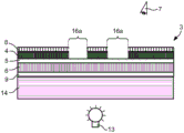
Fig. 1a to 1g schematically show cross-sectional views of an ornamental film 1.
The decorative film 1 shown in fig. 1a, in particular for decorating plastic molded parts, comprises a color paint layer 4, a color paint layer 6 and a transparent laser protective paint layer 5, the transparent laser protective paint layer 5 being arranged between the color paint layer 4 and the color paint layer 6.
Here and in the following, the colored lacquer layer 4 is in particular a first colored lacquer layer in the above-mentioned sense, while the colored lacquer layer 6 is a second colored lacquer layer in the above-mentioned sense. The colored paint layer 4 thus forms in particular a first colored paint layer according to the above-described embodiment, while the colored paint layer 6 forms a second colored paint layer according to the above-described embodiment.
It is thus possible to arrange the colored paint layer 4 on the side of the transparent laser protective paint layer 5 facing the viewer and the colored paint layer 6 on the side of the transparent laser protective paint layer 5 facing away from the viewer. In this way, the colored paint layer 4 can form the side facing the viewer. In this way, the colored lacquer layer 6 can also be arranged in the viewing direction below the transparent laser protective lacquer layer 5 and/or below the colored lacquer layer 4.
The transparent laser protective lacquer layer 5 is preferably a transparent protective lacquer layer, in particular a transparent intermediate protective lacquer layer, which protects the colored lacquer layer 6, in particular the layer below this transparent intermediate protective lacquer layer from mechanical, physical and/or chemical environmental influences from the observer, and/or is provided such that the protective lacquer layer also serves as a spacer or buffer layer for the laser used for removal. Thus, for example, the transparent laser protective lacquer layer 5 shown in fig. 1 can be a transparent protective lacquer layer, in particular a transparent intermediate protective lacquer layer.
The transparent laser protective lacquer layer 5 preferably has a layer thickness of between 0.5 μm and 50 μm, preferably between 2.0 μm and 2.5 μm. The transparent laser protective lacquer layer 5 shown in fig. 1a has a layer thickness of, for example, between 2.0 μm and 2.5 μm.
It is also advantageous if the transparent laser protective lacquer layer 5 has a transmission of at least 25%, preferably at least 75%, more preferably at least 85%, in particular in the wavelength range between 380nm and 780 nm. The transparent laser protective lacquer layer shown in fig. 1a has, for example, a transmission of at least 75%, preferably at least 85%.
It is also conceivable that the transparent laser protective lacquer layer 5 has a transmission in the infrared range, preferably in the near infrared range, more preferably in the wavelength range from 780nm to 1400nm, even more preferably at least 25%, preferably at least 75%, more preferably at least 85% for light with a wavelength of 1064 nm.
It is also reasonable that the transparent laser protective lacquer layer 5 is heat-resistant, in particular able to withstand temperatures of up to 250 ℃, preferably up to 650 ℃, more preferably up to 1000 ℃.
The transparent laser protective lacquer layer 5 preferably diffusely scatters transmitted light, in particular in a wavelength range between 380nm and 780nm, and/or the transparent laser protective lacquer layer 5 has a haze value of at most 50 haze units, preferably at most 20 haze units.
The haze value, expressed in haze units, is preferably determined in transmission to comply with the ASTM D1003 standard. The haze values are measured, for example, using the Byk-Gardener measuring instrument "BYK haze-gard i" from the company Byk-Gardener, Graetried, Germany. Here, the layer or film to be measured is preferably held in the open sample space of the measuring instrument and is placed, in particular for haze values, on a so-called "haze-port" of the instrument, where the measurement is advantageously carried out by means of standard light D65. Next, the result of the measurement is preferably displayed on the screen of the measuring instrument. The haze value is advantageously given in percent (%). Therefore, in this case, the unit of the haze value may be a percentage (%). Therefore, the haze value may preferably range from 0 to 100%. Thus, the units of haze may be percent values or the units of haze may be expressed as percent values. Preferably, the maximum value is 100%. For example, values above 100% may occur due to additional scattered light effects and/or reflection effects occurring during the measurement, in particular in connection with the measurement principle used.
Haze here preferably relates to diffuse scattering, in particular to large-angle scattering, which may lead, for example, to a reduction in the image quality. The particles or inhomogeneities in the material preferably act as scattering centers, at the location of which light is scattered in particular in all spatial directions, wherein advantageously only a small scattering intensity occurs at each spatial angle. This effect is thus preferably referred to as haze or turbidity, in particular leading to a reduction in contrast and/or the manifestation of milky turbidity. In this way, the haze value preferably forms a measure of the haze of a transparent sample, for example a plastic layer or a plastic film.
It is also expedient for the proportion of light deflected in transmission by the transparent laser protective lacquer layer 5 from the direction of the incident light in the angular range of less than 2.5 ° to the total light transmitted by the transparent laser protective lacquer layer 5 to be less than 0.5, preferably less than 0.2. In other words, it is possible for less than 50%, preferably less than 20%, of the transmitted light, in particular in the wavelength range between 380nm and 780nm, to be deflected by the transparent laser protective lacquer layer 5 by more than 2.5 ° from the direction of the incident light beam.
The transparent laser protective lacquer layer 5 preferably has a milky appearance and/or the transparent laser protective lacquer layer 5 deflects more than 30%, preferably more than 45%, more preferably more than 65% of the transmitted light, in particular in the wavelength range between 380nm and 780nm, from the direction of the incident light beam by more than 2.5 °. In other words, it is possible for the transparent laser protective lacquer layer 5 to deflect less than 30%, preferably less than 45%, more preferably less than 65%, of the transmitted light, in particular in the wavelength range between 380nm and 780nm, from the direction of the incident light beam by less than 2.5 °
It is furthermore possible for the proportion of light deflected in transmission by the transparent laser protective lacquer layer 5 from the direction of the incident light by an angle in the range of less than 2.5 ° relative to the total light transmitted by the transparent laser protective lacquer layer 5 to be greater than 0.3, preferably greater than 0.45, more preferably greater than 0.65.
The transparent laser protective lacquer layer 5 can also be colored, in particular the transparent laser protective lacquer layer 5 is colored by means of pigments and/or pigments. Preferably, the degree of coloration of the transparent laser protective lacquer layer 5 is preferably less than 15%, preferably less than 10%, more preferably less than 5%.
However, it is also possible for the transparent laser protective lacquer layer 5 to be colorless and/or transparent and/or for the degree of coloration of the transparent laser protective lacquer layer 5 to be 0%. The degree of coloration of the transparent laser protective lacquer layer 5 shown in fig. 1a is thus, for example, 0%, whereby the transparent laser protective lacquer layer 5 shown in fig. 1a is in particular an unpigmented clear lacquer layer.
The transparent laser protective lacquer layer 5 is preferably a layer made of monomers, oligomers, polymers and/or copolymers, preferably comprising polymethyl methacrylate (PMMA), polyester, Polycarbonate (PC), Polyamide (PA), Polyurethane (PU) and/or polyvinyl chloride (PVC), more preferably comprising PU and/or PVC. It is also possible for the transparent laser protective lacquer layer 5 to have polyacrylate as a binder. The transparent laser protective lacquer layer 5 shown in fig. 1a thus has, for example, polyacrylate as a binder.
Furthermore, the transparent laser protective lacquer layer 5 can also comprise Polyetherimides (PEI) and/or polysulfones, such as, for example, Polyarylethersulfones (PAES).
It is also possible for the transparent laser protective lacquer layer 5 to be thermally cured and/or cured by means of high-energy radiation. The curing is preferably carried out before and/or after the processing of the decoration or transfer film and/or the application of the decoration or transfer film to the substrate.
The transparent laser protective lacquer layer 5 preferably protects the colored lacquer layer 6, in particular the layers arranged below the transparent laser protective lacquer layer 5, from mechanical, physical and/or chemical environmental influences when viewed by an observer.
The colour lacquer layer 4 is preferably a layer made of polyethylene terephthalate (PET), PMMA, polyethylene naphthalate (PEN), PA and/or Acrylonitrile Butadiene Styrene (ABS). Furthermore, the colored lacquer layer 4 can have an acrylate as a binder. The colored lacquer layer 4 shown in fig. 1a thus has an acrylate as a binder.
The color lacquer layer 4 preferably has a layer thickness of between 0.1 μm and 50 μm, preferably between 0.5 μm and 5.0 μm. The colored paint layer 4 shown in fig. 1a has a layer thickness of between 5.0 μm and 5.5 μm, for example.
Furthermore, the colored lacquer layer 4 is preferably opaque and/or advantageously has a transmission of at most 50%, preferably at most 20%, more preferably at most 5%, in particular in the wavelength range between 380nm and 780 nm. The colored lacquer layer 4 shown in fig. 1a has, for example, a transmission of at most 5%.
It is also advantageous if the at least one first pigmented paint layer is pigmented, in particular by means of pigments and/or pigments. The degree of coloration of the colored lacquer layer 4 is preferably between 5% and 35%, preferably between 20% and 25%. The colored paint layer 4 shown in fig. 1a is colored, for example, by a colored pigment and also has a degree of coloring of, for example, between 5% and 35%, preferably between 20% and 25%.
Furthermore, the colored lacquer layer 4 can also be colored in a dark color, in particular black, and/or the colored lacquer layer 4 can also have light-absorbing particles, in particular carbon black.
The color lacquer layer 6 is preferably made of PET, PMMA, PEN, PA and/or ABS and/or has acrylate as a binder. The colored lacquer layer 6 shown in fig. 1a thus has, for example, acrylate as a binder.
Furthermore, the color lacquer layer 6 preferably has a layer thickness of between 0.1 μm and 50 μm, preferably between 1.0 μm and 5.0 μm. The colored lacquer layer 6 shown in fig. 1a has a layer thickness of between 6.0 μm and 7.0 μm, for example.
It is also advantageous if the colored lacquer layer 6 is transparent and/or if the colored lacquer layer 6 has a transmission of at least 10%, preferably at least 25%, more preferably at least 75%, and even more preferably at least 90%, in particular in the wavelength range between 380nm and 780 nm. The colored lacquer layer 6 shown in fig. 1a thus has, for example, a transmission of at least 25%, preferably at least 45%.
It is advantageous if the colored lacquer layer 6 is light-transmitting, in particular is transmissive through the backlight, and/or if the colored lacquer layer 6 is designed such that more than 10%, preferably more than 25%, more preferably more than 75%, and even more preferably more than 90%, of the light emitted by the backlight arranged behind the colored lacquer layer 6 in the viewing direction is transmitted.
As shown in fig. 1a, the colored lacquer layer 6 is preferably designed to be full-surface, in particular, the colored lacquer layer 6 occupies the entire surface when the decorative film 1 is viewed perpendicularly.
It is furthermore advantageous if the colored lacquer layer 6 diffusely scatters light, in particular in a wavelength range between 380nm and 780nm, and/or if the colored lacquer layer 6 has a haze value of at least 50 haze units, preferably at least 75 haze units.
It is also advantageous if the colored lacquer layer 6 deflects more than 50%, preferably more than 75%, more preferably 85% of the transmitted light, in particular in the wavelength range between 380nm and 780nm, more than 2.5 ° from the direction of the incident light beam. In other words, it is possible for the colored lacquer layer 6 to deflect less than 50%, preferably less than 75%, more preferably less than 85% of the transmitted light, in particular in the wavelength range between 380nm and 780nm, by less than 2.5 ° from the direction of the incident light beam.
It is also possible for the ratio of the light deflected in transmission by the colored lacquer layer 6 from the direction of the incident light in an angular range of less than 2.5 ° to the total light transmitted by the colored lacquer layer 6 to be greater than 0.5, preferably greater than 0.75, more preferably greater than 0.85.
It is also possible thereby that the light transmitted through the colored paint layer 6 is diffusely scattered, preferably over a large spatial angle range, more preferably in all spatial directions, so that the light of the point light source in particular is scattered uniformly, so that the colored paint layer 6 appears uniformly illuminated to an observer, in particular despite the illumination with the point light source.
It is thus possible that the colored lacquer layer 6 constitutes a diffuser film and/or that the colored lacquer layer 6 is a diffuser film.
The diffuser film here means in particular a self-supporting, dry layer which can be applied, for example, by adhesion or lamination or the like. Such a diffuser film preferably constitutes an alternative to the second layer of colored lacquer printed or cast by a wet method.
Furthermore, the colored lacquer layer 6 is preferably also colored, in particular by means of pigments and/or pigments. It is preferably possible here for the degree of coloration of the pigmented lacquer layer 6 to be preferably between 5% and 80%, preferably between 40% and 45%. The colored lacquer layer 6 shown in fig. 1a is, for example, a layer colored by means of a color pigment, the degree of coloration being, for example, between 40% and 45%.
According to a further embodiment of the invention, the colored lacquer layer 6 and/or the layer adjoining the second colored lacquer layer 6 is formed as a light conductor layer. The light conductor layer preferably has a light entry face on one end side thereof, into which light of the light source is injected, in particular. Here, the light source may also be arranged such that it is not arranged underneath the decorative film 1 in the viewing direction, but rather, for example, is arranged offset laterally with respect to the decorative film. It is also expedient for the light-conducting layer to have a light exit surface, for example with a surface structure, at least on part of its surface facing the transparent laser protective lacquer layer 5. The light exit area can be designed such that the diffusely scattered light is emitted in a uniformly distributed manner through the light exit area.
In this embodiment, it is also expedient if, as an alternative or in addition to the surface structure, a fluorescent pigment, preferably in the form of pigment particles, is inserted at least in the region of the light exit surface in the material of the colored lacquer layer 6, which consists for example of polycarbonate or PVC as the light conductor layer. In this way, the colored lacquer layer 6 can have fluorescent pigments, preferably in the form of pigment particles, in particular in the region of the light exit surface. In particular, when light is incident into the photoconductor layer, the pigment particles are excited to fluoresce and fluoresce isotropically, that is to say also in the direction of the photoconductor layer. It is thereby possible here for the color of the emitted light to be determined in dependence on the fluorescent dye in the plastic material when the light source is switched on.
In this embodiment, it is possible for the colored lacquer layer 6 to be designed as a light conductor layer, in particular as a self-supporting, dry layer, which is applied, for example, by gluing or lamination or the like. In addition, the colored lacquer layer 6 can also be printed or cast as a light conductor layer in this embodiment by a wet process.
The decorative film 1 shown in fig. 1b, in particular for decorating plastic molded parts, comprises a color paint layer 4, a color paint layer 6, a protective paint layer 8 and a transparent laser protective paint layer 5, the transparent laser protective paint layer 5 being arranged between the color paint layer 4 and the color paint layer 6.
As shown in fig. 1b, a protective lacquer layer 8 is arranged on top of the coloured lacquer layer 4. In this way, if, for example, the colored lacquer layer 4 forms the side of the decorative film 1 facing the observer, the protective lacquer layer 8 is arranged on the side of the decorative film 1 facing the observer.
The expressions "upper" and/or "lower" here refer in particular to the arrangement of a layer relative to another layer when viewed by an observer starting from the viewing direction. Thus, it is appropriate that the expressions "lower" and/or "upper" constitute a reference system. Thus, for example, as shown in fig. 1b, the colored lacquer layer 6 can be arranged below the transparent laser protective lacquer layer 5 in the viewing direction.
It is thus possible for the protective lacquer layer 8 to form a layer directed toward the observer and/or, as shown in fig. 1b, for the protective lacquer layer 8 to be located or arranged in the viewing direction on the colored lacquer layer 4, the colored lacquer layer 6 and/or the transparent laser protective lacquer layer 5. In this way, as shown in fig. 1b, the protective lacquer layer 8 is arranged on the side of the colored lacquer layer 4 facing away from the transparent laser protective lacquer layer 5.
As shown in fig. 1b, the protective lacquer layer 8 preferably completely covers the colored lacquer layer 4 when the viewing direction is perpendicular to the plane defined by the colored lacquer layer 4, the colored lacquer layer 6 and/or the transparent laser protective lacquer layer 5. However, it is also possible for the protective lacquer layer 8 to cover the colour lacquer layer 4 only in regions.
The protective lacquer layer 8 advantageously protects the layer arranged below the protective lacquer layer 8 in the viewing direction against mechanical, physical and/or chemical environmental influences, in particular at least in regions where the protective lacquer layer 8 is not subsequently removed or reapplied.
Alternatively to the embodiment shown in fig. 1b, however, the protective lacquer layer 8 can also be arranged on the side of the decorative film 1 facing away from the viewer. In this way, the protective lacquer layer can be arranged on the side of the colored lacquer layer 6 facing away from the transparent laser protective lacquer layer 5.
The protective lacquer layer 8 is expediently transparent and/or the protective lacquer layer 8 has a transmission of at least 25%, preferably at least 35%, more preferably at least 85%, in particular in the wavelength range between 380nm and 780 nm. The protective lacquer layer 8 shown in fig. 1b is thus a transparent protective lacquer layer, which has a transmission of at least 85%, for example.
The layer thickness of the protective lacquer layer 8 is preferably between 0.5 μm and 50 μm, preferably between 4.0 μm and 4.5 μm. The protective lacquer layer 8 shown in fig. 1b has, for example, a layer thickness of between 4.0 μm and 4.5 μm.
The protective lacquer layer 8 is furthermore preferably a layer of monomers, oligomers, polymers and/or copolymers, preferably comprising polymethyl methacrylate (PMMA), polyester, Polycarbonate (PC), Polyamide (PA), Polyurethane (PU) and/or polyvinyl chloride (PVC), more preferably comprising PU and/or PVC. It is also possible for the protective lacquer layer 8 to have polyacrylate as a binder.
Furthermore, the protective lacquer layer 8 can also have Polyetherimides (PEI) and/or polysulfones, such as, for example, Polyarylethersulfones (PAES).
It is also possible for the protective lacquer layer 8 to be thermally cured and/or cured by means of high-energy radiation. The curing is preferably carried out before and/or after the processing of the decoration film or transfer film and/or the application of the decoration film or transfer film to the substrate.
The protective lacquer layer shown in fig. 1b thus has, for example, acrylates, in particular reaction-curing acrylates, as binders, the curing preferably being carried out thermally and/or by UV radiation.
It is also possible for the protective lacquer layer 8 to be colored, in particular, by means of pigments and/or pigments. The degree of coloration of the protective lacquer layer 8 is preferably less than 15%, preferably less than 10%, more preferably less than 5%.
However, it is also possible for the protective lacquer layer 8 to be colorless and/or transparent and/or for the degree of coloration of the protective lacquer layer to be 0%.
The protective lacquer layer 8 is preferably clear, in particular the protective lacquer layer 8 deflects transmitted light, in particular light in the wavelength range between 380nm and 780nm, by scattering by less than 8%, preferably by less than 4%.
The protective lacquer layer 8 shown in fig. 1b is thus, for example, an unpigmented varnish layer.
In the case of the further embodiments of the layers shown in fig. 1b, in particular of the colored lacquer layer 4, the transparent laser protective lacquer layer 5 and the colored lacquer layer 6, reference is made here to the above description.
The decorative film 1 shown in fig. 1c corresponds to the decorative film shown in fig. 1b, with the difference that the colored lacquer layer 4 is designed as a metal layer 4a and the colored lacquer layer 6 as a metal layer 6 a.
The metal layer 4a is advantageously a metal layer of large optical thickness, which preferably has a lower transmission than the metal layer 6 a. It is also advantageous if the metal layer 6a is a metal layer of optically thin thickness, which preferably has a greater transmission than the metal layer 4 a.
The metal layer 4a advantageously has a transmission of at most 30%, preferably at most 10%, more preferably at most 5%, in particular in the wavelength range between 380nm and 780 nm.
The metal layer 6a preferably has a transmission of more than 10%, preferably more than 25%, more preferably more than 50%, further preferably more than 75%, more preferably more than 90%, in particular in the wavelength range between 380nm and 780 nm.
The layer thickness of the first metal layer 4a is advantageously between 10nm and 1 μm, preferably between 20nm and 300 nm.
The layer thickness of the second metal layer 6a is preferably between 1nm and 500 μm, preferably between 10nm and 80 nm.
This achieves, in particular, that the metal layer 4a is opaque to the observer on account of its low transmission, while the metal layer 6a is transparent.
The functional relationship between the transmission (T) and the optical thickness (OD) is expressed here as follows: OD is log (100/T [% ]).
As described above, the transmission value is determined in particular in the wavelength range from 380nm to 780nm, that is to say in the wavelength range which is visible to the human eye.
The optical thickness of the metal layer depends in particular mainly on the metal used, in addition to the layer thickness used.
In this case, the metal layer 4a and/or the metal layer 6a may be made of aluminum, cobalt, copper, gold, iron, chromium, nickel, silver, platinum, palladium and/or titanium or an alloy of these metals. Aluminum is preferably used for the metal layer 4a with the greater optical thickness due to its smaller penetration depth for light in the wavelength range visible to the human eye, whereas gold, copper, chromium, silver and/or iron is preferably used for the metal layer 6a with the smaller optical thickness due to its greater penetration depth for light in the wavelength range visible to the human eye.
The decorative film 1 shown in fig. 1d corresponds to the decorative film 1 shown in fig. 1b, with the difference that the colored lacquer layer 4b and the colored lacquer layer 6b are designed in a multilayer manner.
As shown in fig. 1d, the color lacquer layer 4d is formed by two partial layers, each of which has a layer thickness of between 0.1 μm and 50 μm, preferably between 0.5 μm and 5.0 μm.
As is also shown in fig. 1d, the color lacquer layer 6b is formed by two partial layers, each having a layer thickness of between 0.1 μm and 50 μm, preferably between 1.0 μm and 5.0 μm.
It is furthermore possible for the two sub-layers to have different colors, in particular colors in the RGB color space or the CMYK color space.
Here, a color may be, in particular, a color point which can be displayed in a color model in the color space, such as, for example, the RGB color model (R ═ red; G ═ green; B ═ blue) or the CMYK color model (C ═ cyan; M ═ magenta; Y ═ yellow; K ═ black).
The decorative film 1 shown in fig. 1e corresponds to the decorative film 1 shown in fig. 1a, with the difference that the colored lacquer layer 4 is formed in some regions.
As shown in fig. 1e, the colored lacquer layer 4 is present in the region 16b and not in the region 16 c.
Such a partially embodied colored lacquer layer 4 can be formed, for example, by a printing method, such as letterpress printing, in particular flexographic printing, lithographic printing, in particular offset printing, gravure printing, inkjet printing and/or serigraphy printing, in particular screen printing. Furthermore, in particular when the colored lacquer layer 4 is formed as a metallic layer 4a, it can also be produced by a metallization process, such as, for example, a CVD process (chemical vapor deposition) and/or a PVD process (physical vapor deposition), preferably using a mask, in particular a mask of a photolithography process.
The term "region" here means in particular a layer or a layer structure defining a surface which, when viewed perpendicular to the plane formed by the decorative film 1, in particular by the color lacquer layer 4, the transparent laser protective lacquer layer 5 and/or the color lacquer layer 6, occupies. Thus, for example, the colored paint layer 4 has regions 16b in which the colored paint layer 4 is present and regions 16c in which the colored paint layer 4 is absent, each of the regions 16b, 16c occupying a defined surface when viewed perpendicularly to the plane defined by the transparent laser protective paint layer 5.
The decorative film shown in fig. 1f corresponds to the decorative film 1 shown in fig. 1b with the difference that the decorative film 1 further comprises an adhesive layer 9.
As shown in fig. 1f, the adhesive layer 9 is arranged on the side of the color lacquer layer 6 facing away from the transparent laser protective lacquer layer 5.
However, the adhesive layer 9 can also be arranged on the side of the color lacquer layer 4 and/or the protective lacquer layer 8 facing away from the transparent laser protective lacquer layer.
In this way, the adhesive layer 9 can form a layer or surface of the decorative film 1 which is directed toward and/or away from the observer and/or can be located or arranged in the viewing direction above the colored lacquer layer 4, the colored lacquer layer 6 and/or the transparent laser protective lacquer layer 5 and/or the adhesive layer 9 can be located or arranged in the viewing direction below the colored lacquer layer 4, the colored lacquer layer 6 and/or the transparent laser protective lacquer layer 5.
Preferably, the adhesive layer 9 partially or completely covers the pigmented lacquer layer 4 or the pigmented lacquer layer 6 when the viewing direction is perpendicular to the plane defined by the pigmented lacquer layer 4, the pigmented lacquer layer 6 and/or the transparent laser protective lacquer layer 5.
It is thereby possible for the decorative film 1 to be applied, in particular fixedly, to the plastic shaped part, in particular to be applied such that the decorative film 2 is fixedly connected to the plastic shaped part.
The expression "fixedly connected" here preferably means that the two elements are permanently connected such that the elements can no longer be mechanically separated without destroying at least one of the elements. In this way, the decorative film 1 and the plastic shaped part are fixedly connected, for example, if there is a permanent connection between the decorative film and the plastic shaped part and the decorative film 1 and/or the plastic shaped part cannot be separated without destroying one of these two elements.
The adhesive layer 9 suitably has a layer thickness of between 0.1 μm and 50 μm, preferably between 7 μm in 0.5 μm, more preferably between 2.5 μm and 3 μm. The adhesive layer 9 shown in fig. 1f has a layer thickness of between 2.5 μm and 3 μm, for example.
The adhesive layer 9 is preferably transparent and/or has a transmission of at least 45%, preferably at least 65%, more preferably at least 95%, in particular in the wavelength range between 380nm and 780 nm. Thus, the adhesive layer 9 shown in fig. 1f has, for example, a transmission of at least 45%.
The adhesive layer 9 is preferably made of a material which is clear and transparent after application to the plastic shaped piece, in particular the adhesive layer 9 is made of a material which deflects light in the wavelength range between 380nm and 780nm by less than 8%, preferably less than 4%, by scattering after application to the plastic shaped piece.
The adhesive layer 9 is preferably a layer made of a polymer and/or copolymer, in particular comprising PMMA, polyester, PU or PVC. It is also possible for the adhesive layer 9 to have an acrylate as a binder. The adhesive layer 9 shown in fig. 1f has, for example, acrylate as a binder.
It is also conceivable that the adhesive layer 9 is colored, the adhesive layer 9 being colored in particular by pigments and/or pigments. The colouring degree of the adhesive layer 9 is advantageously between 5% and 50%, preferably between 30% and 35%. The adhesive layer 9 shown in fig. 1f has, for example, a degree of coloration of between 30% and 35%.
However, it is also conceivable that the adhesive layer 9 is colorless and/or is clear and/or transparent and/or that the degree of coloration of the adhesive layer 9 is 0%.
The decorative film 1 shown in fig. 1g, in particular for decorating plastic molded parts, comprises a colored paint layer 4, a colored paint layer 6, a protective paint layer 8, an electrically functional layer 10 having an electrically functional structure, and a transparent laser protective paint layer 5, the transparent laser protective paint layer 5 being arranged between the colored paint layer 4 and the colored paint layer 6. That is to say, the decorative film 1 shown in fig. 1g corresponds to the decorative film 1 shown in fig. 1b with the difference that the decorative film 1 also has an electrically functional layer 10 which has at least one electrically functional structure.
The electrical functional structures preferably form a touch sensor area that provides a touch pad function.
The term "touch sensor field" is understood here to mean, in particular, a touch-sensitive sensor which makes it possible to control electrical functional elements, for example PDAs, or control elements, for example motor vehicles, which are represented by symbols or words. "touch sensor area" also refers to a multi-touch sensor area that can handle multiple simultaneous touches.
Here, the at least one electrically functional structure may form a capacitive sensor region.
The at least one electrically functional structure may also form a resistive or inductive sensor region.
It is also advantageous if the at least one electrical functional structure additionally has further functional elements, such as, for example, power supply lines, electrical and/or electronic components, such as, for example, integrated circuits.
It is also conceivable for the at least one electrically functional structure to be of single-layer design or else to be of multilayer design. It is furthermore possible for the at least one electrically functional structure to have a reinforcement layer at least in places, which is applied with a metallic pigment layer and/or other electrically conductive layers, such as for example a carbon layer, for example by electroplating and/or by printing.
In this way, the decoration film 1 may be configured as a touch sensor and/or the decoration film 1 is a touch sensor.
It is also advantageous if all layers arranged above the transparent laser protective lacquer layer 5 in the viewing direction are opaque, in particular if all layers arranged above the transparent laser protective lacquer layer 5 in the viewing direction have a maximum transmission of 50%, preferably a maximum of 5%, and/or if all layers arranged below the transparent laser protective lacquer layer 5 in the viewing direction are transparent, in particular if all layers arranged below the transparent laser protective lacquer layer 5 in the viewing direction have a transmission of at least 25%, preferably at least 45%.
Fig. 2 schematically shows a diffusely scattering layer. The functional principle of the diffusely scattering layer is explained with reference to fig. 2. The diffusely scattering layer can be, for example, a colored paint layer 6 which diffusely scatters, in particular, transmitted light, preferably over a large spatial angle range, more preferably in all spatial directions, so that the light, in particular of a point light source, is scattered uniformly, so that the colored paint layer 6 appears uniformly illuminated to the observer 7, in particular despite the illumination with the point light source. In this way, the colored lacquer layer 6 may constitute a diffusing film and/or the colored lacquer layer 6 may be a diffusing film.
Fig. 2 shows that incident light 17a is transmitted through the color lacquer layer 6 and is scattered by the color lacquer layer. Light, in particular in the wavelength range between 380nm and 780nm, is preferably diffusely scattered by the colored lacquer layer 6 and/or the colored lacquer layer 6 has a haze value of at least 50 haze units, preferably of at least 75 haze units.
It is also advantageous if the colored lacquer layer 6 scatters the transmitted light over a large angular range, in particular over a spatial angular range. In this way, the light 17b scattered by the colored lacquer layer 6 is scattered over an angular range, in particular a spatial angular range, of at least 120 °, preferably at least 150 °, more preferably at least 180 °. In other words, the colored paint layer 6 can scatter the transmitted light uniformly, spherically, preferably hemispherically, wherein spherical, preferably hemispherically, identical surface regions obtain substantially the same light fraction of the scattered light.
As described above, it is also possible for the colored lacquer layer 6 to deflect more than 50%, preferably more than 75%, more preferably 85% of the transmitted light, in particular in the wavelength range between 380nm and 780nm, more than 2.5 ° from the direction of the incident light beam.
In particular, due to the distribution of the scattered light 17b over a large angular range, in particular a spatial angular range, the diffusely scattering layer, such as the color lacquer layer 6 here, appears to be uniformly illuminated to the observer 7, even though it is backlit, for example, by a point light source. Thus, a uniformly illuminated surface is preferably produced for the observer by a diffusely scattering layer, such as the colored paint layer 6 here, although behind the diffusely scattering layer, such as the colored paint layer 6 here, for example, a plurality of point light sources, such as, for example, LEDs, are arranged.
Fig. 3 schematically shows a cross-sectional view of the transfer film 2. The transfer film 2, in particular a hot stamping film and/or an in-mold film, advantageously comprises a carrier film 11 and a decorative film 1 that can be peeled off from the carrier film 11. For the design of the decorative film 1, reference is made to the above description.
As shown in fig. 3, the transfer film 2 includes a carrier film 11 and a transfer layer that is peelable from the carrier film 11, and the decoration film 1 constitutes the transfer layer of the transfer film 2, which is provided on the carrier film 11 and is peelable from the carrier film.
Furthermore, as shown in fig. 3, the transfer film 2 advantageously also comprises a release layer 12, which is arranged in particular between the carrier film 11 and the peelable decorative film 1.
The release layer 12 preferably has a layer thickness of between 0.01 μm and 10 μm, preferably between 0.1 μm and 5 μm. In addition, the release layer is made of wax, Polyethylene (PE), polypropylene (PP), cellulose derivatives and/or polyorganosiloxanes.
The carrier film 11 is suitably a transparent carrier film, in particular made of PET, PMMA, PC, ABS or PU, and/or the carrier film 11 has a layer thickness of between 2 μm and 250 μm, preferably between 20 μm and 125 μm.
Such a transfer film 2 can in particular also be used as a thermoprinting film and/or as an in-mold film, in particular as an in-mold decoration film, an insert molding film, an in-mold label film and/or a printing mold design film.
The transfer film 2 can then be used as a hot stamping film, the decorative layer 1 being transferred to a target substrate, for example a plastic shaped part, in particular by means of a heated stamping head which applies pressure to the transfer film 2 during a defined period of time. The carrier film 11 is then preferably removed.
Furthermore, the transfer film 2 can also be used as an in-mold film, in particular as an in-mold decoration film, an insert molding film, an in-mold label film and/or a printing mold design film, in which case in particular the transfer film 2 is inserted into an injection mold and then the transfer film 2 is preferably injection molded behind with a plastic material after the injection mold has been closed, such that the decoration film is fixedly connected to the plastic material. Here, the carrier film 11 is then preferably also removed.
Fig. 4a to 4d schematically show method steps for producing the transfer film 2.
As shown in fig. 4a, first a carrier film 11 is provided. Next, a release layer 12 is optionally applied onto the carrier film 11. Reference is made here to the above description with regard to the design of the release layer 12. The application of the release layer 12 is preferably performed by a printing method or by an evaporation method. In a further step, as shown in fig. 4b, a layer of coloured lacquer 4 is applied. Reference is made here to the above description as regards the design of the colored lacquer layer 4. The application of the colored lacquer layer 4 is preferably carried out here by a printing process and/or a metallisation process. Reference is made here to the above description as regards possible printing processes and/or metallisation processes. In a further step, as shown in fig. 4c, a transparent laser protective lacquer layer 5 is applied, in particular by a printing method. Reference is also made here to the above description for the design of the transparent laser protective lacquer layer 5 and to the possible printing methods. In a further step, as shown in fig. 4d, a colored lacquer layer 6 is applied to the transparent laser protective lacquer layer 5. The application of the colored lacquer layer 6 is carried out here in particular by a printing process, a metallisation process and/or a thermal or cold transfer process. For the printing process, the metallisation process and the transfer process, reference is also made to the above description. Next, the adhesive layer 9 is optionally applied in a further step, for example by a printing process. Reference is made here to the above description as regards the design of the adhesive layer 9. The optional protective lacquer layer 8 shown in fig. 4d can optionally be applied additionally, preferably by printing or casting, before the application of the first coloured lacquer layer 4. Reference is also made here to the above description with regard to the design and possible application method of the protective lacquer layer 8. Furthermore, it is expedient for the applied layers to be precured and/or cured thermally and/or by UV radiation.
The above-described method steps are preferably carried out in the order indicated above.
In the method for producing the transfer film 2, the layers, in particular the color lacquer layer 4, the transparent laser protective lacquer layer 5 and/or the color lacquer layer 6, are applied successively according to the above-described steps, preferably directly, that is to say preferably without further layers being arranged between these layers, in particular between the color lacquer layer 4, the transparent laser protective lacquer layer 5 and/or the color lacquer layer 6. It is thus possible that the decorative film 1 that can be peeled off from the carrier film 11 comprises a colored paint layer 4, a colored paint layer 6 and a transparent laser protective paint layer 5, the transparent laser protective paint layer 5 being arranged between the colored paint layer 4 and the colored paint layer 6.
Fig. 5a to 5c schematically show method steps for decorating a plastic shaped part 3.
First, as shown in fig. 5a, an ornamental film 1 is provided, the ornamental film 1 comprising a colored paint layer 4, a colored paint layer 6 and a transparent laser protective paint layer 5, the transparent laser protective paint layer 5 being arranged between the colored paint layer 4 and the colored paint layer 6. Reference is made here to the above description as to possible embodiments of the decorative film 1. In a further step, as shown in fig. 5b, the decorative film 1 is applied to the plastic shaped part 3. The application of the decorative film is here preferably carried out by a thermal or cold transfer process, more preferably by a hot stamping process and/or an in-mold process. Reference is made here to the above description as to possible application methods. In a further step, which is illustrated in fig. 5c, the colored lacquer layer 4, in particular facing the viewer, is removed in the region 16a by means of a laser.
Here, "removing a layer" means removing a layer partially or completely, in particular by laser cutting and/or laser ablation. If, for example, a layer is removed in a region, the respective layer is partially and/or completely removed in this region. The removal is preferably carried out here by means of laser-based cutting and/or laser ablation. "removal" also means the partial and/or complete removal of a layer, in particular by mechanical or precision mechanical methods, for example by milling and/or grinding and/or drilling.
As shown in fig. 5c, in step b) the decorative film 1 is preferably applied to the plastic shaped part 3 in such a way that the color paint layer 4 forms the side facing the observer 7 and the color paint layer 6 forms the side facing away from the observer.
The method steps described above are advantageously performed in the order indicated above.
Said areas 16a advantageously form decorative elements such as, for example, symbols or letters. Said areas 16a may also constitute logos and/or symbols and/or patterns and/or alphanumerical characters.
It is also preferred that the region 16a has a line width of at least 50 μm, preferably at least 100 μm, when the decorative film 1 and/or the plastic shaped part 3 is viewed perpendicularly, and/or that the region 16a has a line width of at most 2mm, preferably at most 1mm, more preferably at most 0.5mm, when the decorative film 1 and/or the plastic shaped part 3 is viewed perpendicularly.
As shown in fig. 5c, the colored lacquer layer 4 is advantageously removed in the region 16a by means of a laser in such a way that the transparent laser protective lacquer layer 5 is exposed. In this way, the colored lacquer layer 4 can be completely removed in the region 16a in step c).
In step c), the colored paint layer 4 is also preferably removed by the laser in the region 16a in such a way that the layer thickness of the transparent laser protective paint layer 5 in the region 16a in which the colored paint layer 4 has been removed by the laser is substantially equal to the layer thickness of the transparent laser protective paint layer 5 in the region in which the colored paint layer 4 has not been removed by the laser.
In this case, in particular, possible slight surface damage of the transparent laser protective lacquer layer 5 can be tolerated, preferably as long as the total thickness of the transparent laser protective lacquer layer 5 is reduced by not more than 50%, preferably not more than 30%.
It is also possible for the transparent laser protective lacquer layer 5 to be designed in such a way that the layer thickness of the transparent laser protective lacquer layer 5 in the region 16a in which the colored lacquer layer 4 has been removed by means of a laser is reduced by less than 25%, preferably less than 15%, more preferably less than 5%, compared to the region in which the colored lacquer layer 4 has not been removed by means of a laser.
In particular in the end product, it is thereby ensured that the transparent laser protective lacquer layer 5, on the one hand, fulfills its protective function against environmental influences on the layers lying thereunder, and, on the other hand, that the transparent laser protective lacquer layer 5 also fulfills or already fulfills its function as a spacer or buffer layer.
It is furthermore possible that in step b) the decorative film 1 is applied by a transfer method, in particular a thermal transfer and/or cold transfer method, such as, for example, hot stamping, in-mold decoration, insert molding, printing mold design, in-mold labeling, lamination and/or gluing.
In addition, decorative film 1 can also be applied to plastic molding 3 in step b) by back injection molding. In this case, it is reasonable that the method further comprises the following steps:
-placing the decorative film 1 in an injection mould,
back-injection molding the decorative film 1 with a plastic material, such that the decorative film 1 is fixedly connected to the plastic material and the decorative film 1 in particular forms a first surface of the plastic shaped part 3. Here, the cured plastic material preferably forms the plastic shaped part 3.
Fig. 6a to 6c schematically show method steps for decorating a plastic shaped part 3.
First, as shown in fig. 6a, a transfer film 2 is provided comprising a decorative film 1, the decorative film 1 comprising a protective lacquer layer 8, a colored lacquer layer 4, a transparent laser protective lacquer layer 5, a colored lacquer layer 6 and an adhesive layer 9, and the transparent laser protective lacquer layer 5 being arranged between the colored lacquer layer 4 and the colored lacquer layer 6. For further embodiments of the transfer film 2 and of the decoration film 1, reference is made to the above description. In a further step, which is shown in fig. 6b, the decorative film 1 is applied to the plastic shaped part 3. For applying the decorative film 1, a transfer method, in particular a thermal transfer and/or cold transfer method, such as, for example, hot stamping, in-mold decoration, insert molding, printing mold design, in-mold labeling, lamination and/or gluing, is preferably used. In the step shown in fig. 6c, the colored lacquer layer 4 is subsequently removed in the region 16a at least by means of a laser. As shown in fig. 6c, the colored paint layer 4 is provided, in particular, on the side of the plastic shaped part 3 facing the viewer.
Furthermore, as shown in fig. 6c, the protective lacquer layer 8 arranged on the at least one first colored lacquer layer 4 is also removed at least partially, in particular completely, in the region 16 a.
"partial removal" here preferably means that the partially removed layer is modified or destroyed in such a way that it no longer achieves its predetermined properties. In this way, for example, the partially removed protective lacquer layer 8 can no longer achieve a predetermined property which protects the layer arranged thereunder from chemical, physical and/or mechanical environmental influences.
"completely removed" here preferably means that the completely removed layer is removed and/or ablated and/or burnt off and/or evaporated in the corresponding region without residues. In this way, for example, if the colored paint layer 4 is completely removed in the region 16a, in particular by laser cutting and/or laser ablation, the colored paint layer 4 is removed in the region 16a without residues.
In this way, in the region 16a, the protective lacquer layer 8 arranged above the at least one first colored lacquer layer 4, in particular in the viewing direction, can be at least partially removed, so that the layer arranged below the protective lacquer layer 8, in particular the transparent laser protective lacquer layer 5 and/or the colored lacquer layer 6, in the region 16a is not protected against chemical, physical and/or mechanical environmental influences. In other words, in this case, the transparent laser protective lacquer layer 5 and/or the colored lacquer layer 6 are/is subjected to the chemical, mechanical and/or physical environmental influences, so that the transparent laser protective lacquer layer 5 now fulfills the function of protecting the layers disposed thereunder.
In step c), it is also possible to remove, in particular completely remove, all layers arranged in the viewing direction above the transparent laser protective lacquer layer 5 in the region 16 a.
Furthermore, an electrical functional layer having an electrical functional structure can be provided, in particular on the side of the colored lacquer layer 6 facing away from the observer, which electrical functional layer preferably forms a touch sensor region which provides the touch panel function. The electrically functional layer with the electrically functional structure is preferably arranged between the decorative film 1 and the plastic shaped part 3. In this way, the electrical functional layer can be arranged on the side of the colored lacquer layer 6 facing away from the transparent laser protective lacquer layer 5.
It is advantageous here if the electrically functional layer with the electrically functional structure is fixedly connected to the decorative film 1 and the plastic shaped part 3.
Furthermore, a backlight, in particular comprising organic light-emitting diodes (OLED), inorganic light-emitting diodes (LED), micro light-emitting diodes (mlled) and/or quantum dot light-emitting diodes (QLED), can preferably also be arranged on the side of the plastic shaped part 3 facing away from the decorative film 1. The backlight is suitably fixedly mounted, in particular glued or laminated.
The backlight may alternatively or additionally also comprise incandescent, halogen, gas-discharge and/or fluorescent lamps, in particular induction lamps.
The backlighting arrangement preferably comprises a laser and/or a chemical-physical light emitting device, such as for example a luminescent paint or a fluorescent bar.
In addition, a further step, in particular for reworking the plastic molded part 3, can be carried out, in particular after the step described above for decorating the plastic molded part 3. Thus, for example, one can use a compound selected from: a further step of applying a further layer, PU dipping, spraying or covering another plastic component, milling, stamping, deep drawing, polishing and/or embossing the plastic shaped part 3, in particular the plastic shaped part 3 decorated with the decorative film 1, is further processed.
Fig. 7 schematically shows a method step which is carried out during the method for decorating the plastic shaped part 3. The method step shown in fig. 7 is a detail of the above-described step of removing at least the colored lacquer layer 4 in the region 16a by means of the laser 15 a.
As shown in fig. 7, at least the colored lacquer layer 4 is removed by a laser 15 a. As also described above, the protective lacquer layer 8, which is arranged in particular on the colored lacquer layer 4 and forms the surface of the plastic shaped part 3, is also at least partially removed.
Here, a laser 15a having a beam diameter of at least 50 μm, preferably at least 100 μm, in the focal point is preferably used.
The laser beam 15b may also be focused by one or more lenses, in particular a lens having a focal length of between 100mm and 500mm, preferably between 200mm and 300mm, more preferably 254 mm.
It is furthermore preferred to use a laser 15a, in particular a fiber laser, said laser 15a emitting coherent light in the infrared range, preferably in the near infrared range, more preferably in the wavelength range of 780nm to 1400nm, even more preferably at a wavelength of 1064 nm.
Preferably, the laser power is between 0.05W and 100W, preferably between 1W and 20W, more preferably between 5W and 10W.
The laser beam 15b is expediently guided along the region 16a by means of a deflectable mirror, in particular by means of a laser scanning module.
According to another embodiment of the invention, the laser 15a is operated at a writing speed of at most 3000mm/s, preferably between 500mm/s and 2500mm/s, and/or the laser 15a is operated at a pulse frequency between 1Hz and 1000kHz, preferably between 1kHz and 200 kHz.
In addition, however, the laser 15a can also be operated continuously. However, pulsed lasers are preferably used, since the thermal load on the plastic shaped part 3 is reduced in particular compared to continuously operating lasers.
The parameters of the laser 15a are selected here in particular as a function of the layers 4, 8 to be removed and the layers 5, 6, 9, 3 not to be removed. The parameters are selected in particular as a function of the layer thickness and the material of the layer 4, 8 to be removed and/or of the layer 5, 6, 9, 3 not to be removed. In this way, the parameters of the laser 15a are also influenced by the material of the plastic shaped part 3, since this material is influenced in particular by the heat generated by the laser 15a or the laser beam 15 b. Therefore, in particular to prevent deformation of the plastic molded part 3, the material of the plastic molded part 3 is also taken into consideration when selecting the laser parameters. In addition, in particular by the parameters: the writing speed, the pulse frequency and the laser power influence the penetration depth of the laser 15a or the laser beam 15 b. In addition, the laser parameters are advantageously also selected according to the design of the region 16a to be removed. Here, layout size, line width, and fill effect are given in particular. This includes, for example, the number of fills and the laser direction, the profile and the repetition of the fills as well as the order of the components of the layout.
Exemplary laser parameters are given below for a plastic shaped part 3 made of transparent ABS decorated with a decorative film 1, which is processed according to the method described above:
laser power: 8W
Laser frequency: 50kHz
-writing speed: 2000mm/s
-wavelength: 1064nm
Fig. 8a to 8e schematically show cross-sectional views of the plastic shaped part 3.
The plastic shaped part 3 shown in fig. 8a comprises a decorative film 1. The decorative film 1 here comprises a colored paint layer 4, a colored paint layer 6 and a transparent laser protective paint layer 5, the transparent laser protective paint layer 5 being arranged between the colored paint layer 4 and the colored paint layer 6. In addition, the colored lacquer layer 4, in particular facing the observer, is removed in the region 16a by means of a laser. Reference is made here to the above description as to the design of the layers 4, 5 and 6.
It is also advantageous, as shown in fig. 8a, for the plastic shaped part to have a layer 14 made of thermoplastic material, which is arranged in particular on the side of the colored paint layer 6 facing away from the viewer. In this way, the at least one layer 14 made of thermoplastic material can be arranged on the side of the colored lacquer layer 6 facing away from the viewer.
The region 16a preferably has a line width of at least 50 μm, preferably at least 100 μm when the decoration film 1 is viewed perpendicularly. However, the regions 16a may also have a line width of at most 2mm, preferably at most 1mm, more preferably at most 0.5mm, when viewed perpendicularly to the decorative film 1.
For further embodiments of the region 16a, reference is made here to the above description.
Furthermore, the plastic shaped part can have a layer thickness of 0.5mm to 10mm, preferably 0.8mm to 5 mm.
The layer 14 made of thermoplastic material is preferably transparent, in particular the layer 14 made of thermoplastic material has a transparency of between 5% and 98%, in particular in the wavelength range of 380nm to 780 nm.
The layer 14 made of thermoplastic material is preferably formed of one of the following materials: ABS, PC, ABS/PC, PC/ABS, PMMA, polyethylene (PP), PA, Thermoplastic Polyurethane (TPU).
It is furthermore conceivable for the layer 14 made of thermoplastic material to be colored, in particular for the layer 14 made of thermoplastic material to be colored by means of pigments and/or pigments. Preferably, the layer 14 made of thermoplastic material has a degree of coloration preferably lower than 15%, preferably lower than 10%, more preferably lower than 5%.
The plastic shaped part 3 shown in fig. 8b corresponds to the plastic shaped part 3 shown in fig. 8a, with the difference that the plastic shaped part 3, in particular the decorative film 1 which the plastic shaped part 3 comprises, also comprises a protective lacquer layer 8 and an adhesive layer 9, as described above, the protective lacquer layer 8 being at least partially removed in the region 16 a. Reference is made here to the above description as regards the design of the protective lacquer layer 8 and the adhesive layer 9.
The plastic shaped part 3 shown in fig. 8c corresponds to the plastic shaped part 3 shown in fig. 8b, with the difference that the plastic shaped part 3, in particular the decorative film 1 which the plastic shaped part 3 comprises, in particular on the colored lacquer layer 6 facing away from the viewer, also comprises an electrical functional layer 10 with an electrical functional structure which preferably forms a touch sensor region which provides the touch pad function.
As shown in fig. 8c, the functional layer 10 with electrically functional structure is arranged between the decorative film 1 and the layer 14 made of thermoplastic material. In this case, the functional layer 10 is preferably arranged on the side of the color lacquer layer 6 facing away from the transparent laser protective lacquer layer 5.
With regard to further possible embodiments of the electrical functional layer 10 with an electrical functional structure, reference is made to the above description.
In this way, the plastic molded article 3 shown in fig. 8c, particularly the plastic molded article 3 decorated with the decoration film 1, constitutes, for example, a touch sensor.
The plastic shaped part 3 shown in fig. 8d likewise corresponds to the plastic shaped part shown in fig. 8b, with the difference that the plastic shaped part 3 also has a backlight 13, in particular comprising organic light-emitting diodes (OLED), inorganic light-emitting diodes (LED) and/or micro light-emitting diodes (mLED) and/or quantum dot light-emitting diodes (QLED), the backlight 13 preferably being arranged on the side of the layer 14 made of thermoplastic material facing away from the decorative film 1.
With regard to further possible embodiments of the backlight 13, reference is made to the above description.
The plastic shaped part 3 shown in fig. 8e corresponds to the plastic shaped part 3 shown in fig. 8c with the difference that, like the plastic shaped part 3 shown in fig. 8d, the plastic shaped part 3 also has a backlight 13, which backlight 13 is preferably arranged on the side of the layer 14 made of thermoplastic material facing away from the decorative film 1.
Reference is also made here to the above description with regard to possible embodiments of the backlight 13 and/or of the electrically functional layer 10 with electrically functional structures.
Fig. 9 schematically shows a top view of the decorative film 1 and/or of the plastic shaped part 3 comprising the decorative film 1. As shown in fig. 9, the decorative film 1 and/or the plastic shaped part 3 comprising the decorative film 1 has a region 16a in which at least the colored paint layer 4, 4a, 4b has been removed by means of a laser. Thus, as shown in fig. 9, said area 16a constitutes a decorative element, such as for example a symbol or a text. But the areas may also display patterns and/or logos and/or alphanumeric characters.
Fig. 9 shows, on the one hand, a plan view of the decorative film 1 in which the colored lacquer layer 4, 4a, 4b, in particular facing the viewer, is removed, in particular completely removed, in the region 16a, so that the transparent laser protective lacquer layer 5 is exposed, in particular in the region 16 a. Fig. 9 also shows a top view of a plastic shaped part 3, which comprises a decorative film 1, which is likewise applied to the plastic shaped part as described above and is designed according to the above-described embodiment. That is, fig. 9 is a plan view of both the decorative film 1 and the plastic molded article 3 decorated with the decorative film 1.
With regard to the further embodiments of the region 16a and/or of the decorative film 1 and/or of the plastic shaped part 3, in particular with regard to the possible layer structure of the decorative film 1 and/or of the plastic shaped part 3, reference is also made here to the above description.
List of reference numerals
1 decorative film
2 transfer printing film
3 Plastic moulded part
4. 4a, 4b first colour lacquer layer
5 transparent laser protective paint layer
6. 6a, 6b second colour lacquer layer
7 observer
8 protective paint layer
9 adhesive layer
10 electric function layer
11 carrier film
12 peeling layer
13 backlight device
14 layer made of thermoplastic material
15a, 15b laser, laser beam
16a, 16b, 16c region
17a, 17b incident light, scattered light.