CN112740675A - Method and apparatus for encoding/decoding image using intra prediction - Google Patents
Method and apparatus for encoding/decoding image using intra prediction Download PDFInfo
- Publication number
- CN112740675A CN112740675A CN201980058354.2A CN201980058354A CN112740675A CN 112740675 A CN112740675 A CN 112740675A CN 201980058354 A CN201980058354 A CN 201980058354A CN 112740675 A CN112740675 A CN 112740675A
- Authority
- CN
- China
- Prior art keywords
- block
- prediction
- mode
- current block
- intra prediction
- Prior art date
- Legal status (The legal status is an assumption and is not a legal conclusion. Google has not performed a legal analysis and makes no representation as to the accuracy of the status listed.)
- Granted
Links
Images


Classifications
-
- H—ELECTRICITY
- H04—ELECTRIC COMMUNICATION TECHNIQUE
- H04N—PICTORIAL COMMUNICATION, e.g. TELEVISION
- H04N19/00—Methods or arrangements for coding, decoding, compressing or decompressing digital video signals
- H04N19/10—Methods or arrangements for coding, decoding, compressing or decompressing digital video signals using adaptive coding
- H04N19/102—Methods or arrangements for coding, decoding, compressing or decompressing digital video signals using adaptive coding characterised by the element, parameter or selection affected or controlled by the adaptive coding
- H04N19/103—Selection of coding mode or of prediction mode
- H04N19/105—Selection of the reference unit for prediction within a chosen coding or prediction mode, e.g. adaptive choice of position and number of pixels used for prediction
-
- H—ELECTRICITY
- H04—ELECTRIC COMMUNICATION TECHNIQUE
- H04N—PICTORIAL COMMUNICATION, e.g. TELEVISION
- H04N19/00—Methods or arrangements for coding, decoding, compressing or decompressing digital video signals
- H04N19/10—Methods or arrangements for coding, decoding, compressing or decompressing digital video signals using adaptive coding
- H04N19/102—Methods or arrangements for coding, decoding, compressing or decompressing digital video signals using adaptive coding characterised by the element, parameter or selection affected or controlled by the adaptive coding
- H04N19/103—Selection of coding mode or of prediction mode
- H04N19/11—Selection of coding mode or of prediction mode among a plurality of spatial predictive coding modes
-
- H—ELECTRICITY
- H04—ELECTRIC COMMUNICATION TECHNIQUE
- H04N—PICTORIAL COMMUNICATION, e.g. TELEVISION
- H04N19/00—Methods or arrangements for coding, decoding, compressing or decompressing digital video signals
- H04N19/10—Methods or arrangements for coding, decoding, compressing or decompressing digital video signals using adaptive coding
- H04N19/102—Methods or arrangements for coding, decoding, compressing or decompressing digital video signals using adaptive coding characterised by the element, parameter or selection affected or controlled by the adaptive coding
- H04N19/119—Adaptive subdivision aspects, e.g. subdivision of a picture into rectangular or non-rectangular coding blocks
-
- H—ELECTRICITY
- H04—ELECTRIC COMMUNICATION TECHNIQUE
- H04N—PICTORIAL COMMUNICATION, e.g. TELEVISION
- H04N19/00—Methods or arrangements for coding, decoding, compressing or decompressing digital video signals
- H04N19/10—Methods or arrangements for coding, decoding, compressing or decompressing digital video signals using adaptive coding
- H04N19/102—Methods or arrangements for coding, decoding, compressing or decompressing digital video signals using adaptive coding characterised by the element, parameter or selection affected or controlled by the adaptive coding
- H04N19/12—Selection from among a plurality of transforms or standards, e.g. selection between discrete cosine transform [DCT] and sub-band transform or selection between H.263 and H.264
- H04N19/122—Selection of transform size, e.g. 8x8 or 2x4x8 DCT; Selection of sub-band transforms of varying structure or type
-
- H—ELECTRICITY
- H04—ELECTRIC COMMUNICATION TECHNIQUE
- H04N—PICTORIAL COMMUNICATION, e.g. TELEVISION
- H04N19/00—Methods or arrangements for coding, decoding, compressing or decompressing digital video signals
- H04N19/10—Methods or arrangements for coding, decoding, compressing or decompressing digital video signals using adaptive coding
- H04N19/134—Methods or arrangements for coding, decoding, compressing or decompressing digital video signals using adaptive coding characterised by the element, parameter or criterion affecting or controlling the adaptive coding
- H04N19/157—Assigned coding mode, i.e. the coding mode being predefined or preselected to be further used for selection of another element or parameter
- H04N19/159—Prediction type, e.g. intra-frame, inter-frame or bidirectional frame prediction
-
- H—ELECTRICITY
- H04—ELECTRIC COMMUNICATION TECHNIQUE
- H04N—PICTORIAL COMMUNICATION, e.g. TELEVISION
- H04N19/00—Methods or arrangements for coding, decoding, compressing or decompressing digital video signals
- H04N19/10—Methods or arrangements for coding, decoding, compressing or decompressing digital video signals using adaptive coding
- H04N19/169—Methods or arrangements for coding, decoding, compressing or decompressing digital video signals using adaptive coding characterised by the coding unit, i.e. the structural portion or semantic portion of the video signal being the object or the subject of the adaptive coding
- H04N19/17—Methods or arrangements for coding, decoding, compressing or decompressing digital video signals using adaptive coding characterised by the coding unit, i.e. the structural portion or semantic portion of the video signal being the object or the subject of the adaptive coding the unit being an image region, e.g. an object
- H04N19/176—Methods or arrangements for coding, decoding, compressing or decompressing digital video signals using adaptive coding characterised by the coding unit, i.e. the structural portion or semantic portion of the video signal being the object or the subject of the adaptive coding the unit being an image region, e.g. an object the region being a block, e.g. a macroblock
-
- H—ELECTRICITY
- H04—ELECTRIC COMMUNICATION TECHNIQUE
- H04N—PICTORIAL COMMUNICATION, e.g. TELEVISION
- H04N19/00—Methods or arrangements for coding, decoding, compressing or decompressing digital video signals
- H04N19/10—Methods or arrangements for coding, decoding, compressing or decompressing digital video signals using adaptive coding
- H04N19/169—Methods or arrangements for coding, decoding, compressing or decompressing digital video signals using adaptive coding characterised by the coding unit, i.e. the structural portion or semantic portion of the video signal being the object or the subject of the adaptive coding
- H04N19/182—Methods or arrangements for coding, decoding, compressing or decompressing digital video signals using adaptive coding characterised by the coding unit, i.e. the structural portion or semantic portion of the video signal being the object or the subject of the adaptive coding the unit being a pixel
-
- H—ELECTRICITY
- H04—ELECTRIC COMMUNICATION TECHNIQUE
- H04N—PICTORIAL COMMUNICATION, e.g. TELEVISION
- H04N19/00—Methods or arrangements for coding, decoding, compressing or decompressing digital video signals
- H04N19/10—Methods or arrangements for coding, decoding, compressing or decompressing digital video signals using adaptive coding
- H04N19/169—Methods or arrangements for coding, decoding, compressing or decompressing digital video signals using adaptive coding characterised by the coding unit, i.e. the structural portion or semantic portion of the video signal being the object or the subject of the adaptive coding
- H04N19/186—Methods or arrangements for coding, decoding, compressing or decompressing digital video signals using adaptive coding characterised by the coding unit, i.e. the structural portion or semantic portion of the video signal being the object or the subject of the adaptive coding the unit being a colour or a chrominance component
-
- H—ELECTRICITY
- H04—ELECTRIC COMMUNICATION TECHNIQUE
- H04N—PICTORIAL COMMUNICATION, e.g. TELEVISION
- H04N19/00—Methods or arrangements for coding, decoding, compressing or decompressing digital video signals
- H04N19/46—Embedding additional information in the video signal during the compression process
-
- H—ELECTRICITY
- H04—ELECTRIC COMMUNICATION TECHNIQUE
- H04N—PICTORIAL COMMUNICATION, e.g. TELEVISION
- H04N19/00—Methods or arrangements for coding, decoding, compressing or decompressing digital video signals
- H04N19/50—Methods or arrangements for coding, decoding, compressing or decompressing digital video signals using predictive coding
- H04N19/593—Methods or arrangements for coding, decoding, compressing or decompressing digital video signals using predictive coding involving spatial prediction techniques
-
- H—ELECTRICITY
- H04—ELECTRIC COMMUNICATION TECHNIQUE
- H04N—PICTORIAL COMMUNICATION, e.g. TELEVISION
- H04N19/00—Methods or arrangements for coding, decoding, compressing or decompressing digital video signals
- H04N19/70—Methods or arrangements for coding, decoding, compressing or decompressing digital video signals characterised by syntax aspects related to video coding, e.g. related to compression standards
Landscapes
- Engineering & Computer Science (AREA)
- Multimedia (AREA)
- Signal Processing (AREA)
- Physics & Mathematics (AREA)
- Discrete Mathematics (AREA)
- General Physics & Mathematics (AREA)
- Compression Or Coding Systems Of Tv Signals (AREA)
Abstract
一种根据本发明的用于对图像进行编码/解码的方法和装置可以:确定用于当前块的帧内预测的参考区域;基于预定的MPM候选组得出当前块的帧内预测模式;以及基于参考区域和帧内预测模式对当前块执行帧内预测。

A method and apparatus for encoding/decoding an image according to the present invention may: determine a reference region for intra prediction of a current block; derive an intra prediction mode of the current block based on a predetermined MPM candidate group; and Intra prediction is performed on the current block based on the reference region and the intra prediction mode.
Description
Technical Field
The present invention relates to an image encoding/decoding method and apparatus.
Background
Recently, demands for high-resolution and high-quality images such as High Definition (HD) images and Ultra High Definition (UHD) images are increasing in various application fields, and thus, efficient image compression techniques are being discussed.
There are various techniques, for example, an inter prediction technique of predicting pixel values included in a current picture from pictures before or after the current picture using a video compression technique, an intra prediction technique of predicting pixel values included in the current picture by using pixel information in the current picture, an entropy coding technique of allocating short codes to values having a high frequency of occurrence and long codes to values having a low frequency of occurrence. Image data can be efficiently compressed, transmitted, or stored by using such image compression techniques.
Disclosure of Invention
Technical problem
The invention aims to provide a method and a device for deriving an intra-frame prediction mode.
The invention aims to provide an intra-frame prediction method and device according to component types.
The invention aims to provide a block division method and device for intra-frame prediction.
Technical solution
The image encoding/decoding method and apparatus of the present invention may: determining a reference region for intra prediction of a current block; deriving an intra prediction mode of the current block based on a predetermined MPM candidate group; and performing intra prediction on the current block based on the reference region and the intra prediction mode.
In the image encoding/decoding method and apparatus of the present invention, the MPM candidate groups may be divided into a first group and a second group, the first group may include a default mode predefined in the decoding apparatus, and the second group may include intra prediction modes of neighboring blocks adjacent to the current block.
In the image encoding/decoding method and apparatus of the present invention, the intra prediction mode of the current block may be derived by selectively using one of the first group or the second group.
In the image encoding/decoding method and apparatus of the present invention, determining the reference region may include: selecting one of a plurality of pixel rows predefined in the decoding means; and determining the selected pixel row as a reference region.
In the image encoding/decoding method and apparatus of the present invention, the plurality of predefined pixel rows may include at least one of: a first pixel row adjacent to the current block; a second pixel row adjacent to the first pixel row; a third pixel row adjacent to the second pixel row; or a fourth pixel row adjacent to the third pixel row.
In the image encoding/decoding method and apparatus of the present invention, the default mode may be composed of only the non-directional mode, and the non-directional mode may include at least one of a planar mode or a DC mode.
In the image encoding/decoding method and apparatus of the present invention, the second group may further include a mode obtained by adding or subtracting N values to or from intra prediction modes of neighboring blocks, and the N value may be 1, 2, or 3.
The image encoding/decoding method and apparatus of the present invention may obtain a first flag from a bitstream, and the first flag may indicate whether an intra prediction mode of a current block is derived from a first group.
In the image encoding/decoding method and apparatus of the present invention, when the value of the first flag is a first value, the intra prediction mode of the current block may be set to the MPM belonging to the first group, and when the value of the first flag is a second value, the intra prediction mode of the current block may be derived based on the second group and the MPM index.
In the image encoding/decoding method and apparatus of the present invention, the first flag may be signaled only when the reference region of the current block is determined as the first pixel line.
The image encoding/decoding method and apparatus of the present invention may determine an intra prediction mode of a current block, and perform intra prediction on the current block based on the determined intra prediction mode.
In the image encoding/decoding method and apparatus of the present invention, the intra prediction mode of the current block can be derived for the luminance block and the chrominance block, respectively.
In the image encoding/decoding method and apparatus of the present invention, the intra prediction mode of the luminance block is derived based on the MPM list and the MPM index, and the MPM list may include at least one of an intra prediction mode (mode a), a mode a + n, a mode a-n, or a default mode of the neighboring block.
The image encoding/decoding method and apparatus of the present invention may: specifying a luma region for inter-component reference of a chroma block; performing down-sampling on the luminance area; deriving parameters for inter-component reference of the chroma block; and predicting the chroma block based on the downsampled luma block and the parameters.
In the image encoding/decoding method and apparatus of the present invention, the current block is divided into a plurality of sub-blocks, and the division may be performed based on at least one of the size or the shape of the current block.
Advantageous effects
According to the present invention, prediction can be more accurately and efficiently performed by an intra prediction mode derived based on an MPM candidate group.
According to the present invention, the efficiency of inter prediction based on inter-component reference can be improved.
The present invention can improve the efficiency of intra prediction encoding/decoding by adaptive block division.
Drawings
Fig. 1 is a block diagram illustrating an image encoding apparatus according to an embodiment of the present invention.
Fig. 2 is a block diagram illustrating an image decoding apparatus according to an exemplary embodiment of the present invention.
Fig. 3 illustrates a block division type according to an embodiment to which the present invention is applied.
Fig. 4 illustrates a block division method based on a tree structure as an embodiment to which the present invention is applied.
Fig. 5 is an exemplary diagram illustrating an intra prediction mode predefined in an image encoding/decoding apparatus.
Fig. 6 illustrates an intra prediction method according to an embodiment to which the present invention is applied.
Fig. 7 illustrates an intra prediction method in units of sub blocks as an embodiment to which the present invention is applied.
Fig. 8 illustrates a prediction method based on inter-component reference in an embodiment to which the present disclosure is applied.
Fig. 9 to 12 illustrate a method of determining a prediction method based on prediction method selection information as an embodiment to which the present invention is applied.
Best mode for carrying out the invention
The image encoding/decoding method and apparatus of the present invention may: determining a reference region for intra prediction of a current block; deriving an intra prediction mode of the current block based on a predetermined MPM candidate group; and performing intra prediction on the current block based on the reference region and the intra prediction mode.
In the image encoding/decoding method and apparatus of the present invention, the MPM candidate groups may be divided into a first group and a second group, the first group may include a default mode predefined in the decoding apparatus, and the second group may include intra prediction modes of neighboring blocks adjacent to the current block.
In the image encoding/decoding method and apparatus of the present invention, the intra prediction mode of the current block may be derived by selectively using one of the first group or the second group.
In the image encoding/decoding method and apparatus of the present invention, determining the reference region may include selecting one pixel row of a plurality of pixel rows predefined in the decoding apparatus, and determining the selected pixel row as the reference region.
In the image encoding/decoding method and apparatus of the present invention, the plurality of predefined pixel rows may include at least one of: a first pixel row adjacent to the current block; a second pixel row adjacent to the first pixel row; a third pixel row adjacent to the second pixel row; or a fourth pixel row adjacent to the third pixel row.
In the image encoding/decoding method and apparatus of the present invention, the default mode may be composed of only the non-directional mode, and the non-directional mode may include at least one of a planar mode or a DC mode.
In the image encoding/decoding method and apparatus of the present invention, the second group may further include a mode obtained by adding or subtracting N values to or from intra prediction modes of neighboring blocks, and the N value may be 1, 2, or 3.
The image encoding/decoding method and apparatus of the present invention may obtain a first flag from a bitstream, and the first flag may indicate whether an intra prediction mode of a current block is derived from a first group.
In the image encoding/decoding method and apparatus of the present invention, when the value of the first flag is a first value, the intra prediction mode of the current block may be set to the MPM belonging to the first group, and when the value of the first flag is a second value, the intra prediction mode of the current block may be derived based on the second group and the MPM index.
In the image encoding/decoding method and apparatus of the present invention, the first flag may be signaled only when the reference region of the current block is determined as the first pixel line.
The image encoding/decoding method and apparatus of the present invention may determine an intra prediction mode of a current block, and perform intra prediction on the current block based on the determined intra prediction mode.
In the image encoding/decoding method and apparatus of the present invention, the intra prediction mode of the current block can be derived for the luminance block and the chrominance block, respectively.
In the image encoding/decoding method and apparatus of the present invention, the intra prediction mode of the luminance block is derived based on the MPM list and the MPM index, and the MPM list may include at least one of an intra prediction mode (mode a), a mode a + n, a mode a-n, or a default mode of the neighboring block.
The image encoding/decoding method and apparatus of the present invention may: specifying a luma region for inter-component reference of a chroma block; performing down-sampling on the luminance area; deriving parameters for inter-component reference of the chroma block; and predicting the chroma block based on the downsampled luma block and the parameters.
In the image encoding/decoding method and apparatus of the present invention, the current block is divided into a plurality of sub-blocks, and the division may be performed based on at least one of the size or the shape of the current block.
Detailed Description
The invention is susceptible to variations and modifications in various ways and may be described with reference to different exemplary embodiments, some of which will be described and illustrated in the accompanying drawings. However, these embodiments are not intended to limit the present invention, but are to be understood as including all modifications, equivalents and alternatives falling within the spirit and technical scope of the present invention. In the drawings, like reference numerals refer to like elements throughout.
Although the terms first, second, etc. may be used to describe various elements, these elements should not be limited by these terms. These terms are only used to distinguish one element from another. For example, a first element could be termed a second element, and, similarly, a second element could be termed a first element, without departing from the teachings of the present invention. The term "and/or" includes any and all combinations of the plurality of associated listed items.
It will be understood that when an element is referred to as being "connected" or "coupled" to another element, it can be directly connected or coupled to the other element or intervening elements. In contrast, when an element is referred to as being "directly connected to" or "directly coupled to" another element, there are no intervening elements present.
The terminology used herein is for the purpose of describing particular embodiments only and is not intended to be limiting of the invention. As used herein, the singular forms "a", "an" and "the" are intended to include the plural forms as well, unless the context clearly indicates otherwise. It will be further understood that the terms "comprises" and/or "comprising," when used in this specification, specify the presence of stated features, integers, steps, operations, elements, and/or components, but do not preclude the presence or addition of one or more other features, integers, steps, operations, elements, components, and/or groups thereof.
Hereinafter, exemplary embodiments of the present invention will be described in detail with reference to the accompanying drawings. In the drawings, like reference numerals refer to like elements throughout, and redundant description of the same elements will be omitted herein.
Fig. 1 is a block diagram illustrating an image encoding apparatus according to an embodiment of the present invention.
Referring to fig. 1, the image encoding apparatus 100 includes a picture dividing unit 110, prediction units 120 and 125, a transform unit 130, a quantization unit 135, a rearrangement unit 160, an entropy encoding unit 165, an inverse quantization unit 140, an inverse transform unit 145, a filter unit 150, and a memory 155.
Each of the elements shown in fig. 1 is shown separately to represent different feature functions in the encoding apparatus, but does not mean that each element is composed of separate hardware or one software element. That is, for convenience of description, elements are independently arranged, wherein at least two elements may be combined into a single element, or a single element may be divided into a plurality of elements to perform functions. It is noted that embodiments in which some elements are integrated into one combined element and/or elements are divided into a plurality of separate elements without departing from the spirit of the present invention are included in the scope of the present invention.
Some elements are not essential to the essential function of the present invention, but may be optional constituent elements only for improving performance. The present invention may be implemented by including only constituent elements necessary for the embodiment of the present invention (without including only constituent components for improving performance). A structure including only necessary constituent elements (not including only optional constituent elements for improving performance) falls within the scope of the present invention.
The picture division unit 110 may divide an input picture into at least one processing unit. In this case, the processing unit may be a Prediction Unit (PU), a Transform Unit (TU), or a Coding Unit (CU). The picture division unit 110 may divide one picture into a plurality of combinations of coding units, prediction units, and transformation units, and select one combination of coding units, prediction units, and transformation units based on a predetermined criterion (e.g., a cost function) to encode the picture.
For example, one picture may be divided into a plurality of coding units. In order to divide a picture into coding units, a recursive tree structure such as a quadtree structure may be used. One picture or the largest coding block (largest coding unit) as a root may be divided into other coding units, and may be divided with as many child nodes as the number of divided coding units. Coding units that are no longer partitioned according to certain constraints become leaf nodes. That is, when it is assumed that only square division is possible for one coding unit, one coding unit may be divided into up to four different coding units.
In the embodiments of the present invention, the coding unit may be used to refer not only to a coding unit but also to a decoding unit.
The prediction units may be blocks divided in a shape such as at least one square or rectangle having the same size within one coding unit, or one of the prediction units divided within one coding unit may have a shape and/or size different from another prediction unit.
When a prediction unit performing intra prediction based on a coding unit is not a minimum coding unit, intra prediction may be performed without being divided into a plurality of prediction units N × N.
The prediction units 120 and 125 may include an inter prediction unit 120 for performing inter prediction and an intra prediction unit 125 for performing intra prediction. The prediction units 120 and 125 may determine which one of inter prediction and intra prediction is performed on the prediction unit, and may determine specific information (e.g., an intra prediction mode, a motion vector, and a reference picture) of the determined prediction method. Here, the processing unit on which prediction is performed may be different from the processing unit on which the prediction method and the specific information are determined. For example, a prediction method and a prediction mode may be determined for each prediction unit, while prediction may be performed for each transform unit. A residual value (residual block) between the generated prediction block and the original block may be input to the transform unit 130. Also, prediction mode information, motion vector information, and the like for prediction may be encoded by the entropy encoding unit 165 together with the residual value and transmitted to the decoding apparatus. When a specific coding mode is used, the original block may be encoded and transmitted to the decoding apparatus without generating a prediction block by the prediction units 120 and 125.
The inter prediction unit 120 may predict the prediction unit based on information about at least one picture among a previous picture of the current picture and a picture subsequent to the current picture. In some cases, the inter prediction unit 120 may predict the prediction unit based on information of a partially encoded region in the current picture. The inter prediction unit 120 may include a reference picture interpolation unit, a motion prediction unit, and a motion compensation unit.
The reference picture interpolation unit may be provided with reference picture information from the memory 155, and may generate pixel information less than or equal to integer pixels on the reference picture. In the case of a luminance pixel, pixel information less than or equal to an integer pixel may be generated in 1/4 pixel units using a DCT-based 8-tap interpolation filter having a variable filter coefficient. In the case of chroma pixels, pixel information less than or equal to integer pixels may be generated in 1/8 pixel units using a DCT-based 4-tap interpolation filter with variable filter coefficients.
The motion prediction unit may perform motion prediction based on the reference picture interpolated by the reference picture interpolation unit. The motion vector may be calculated using various methods, such as a full search based block matching algorithm (FBMA), a three-step search (TSS) algorithm, and a new three-step search (NTS) algorithm. The motion vector has a motion vector value in units of 1/2 or 1/4 pixels based on the interpolated pixel. The motion prediction unit may predict the current prediction unit using different motion prediction methods. Various methods such as skip mode, merge mode, and Advanced Motion Vector Prediction (AMVP) mode, intra block copy mode, etc. may be used as the motion prediction method.
The intra prediction unit 125 may generate a prediction unit based on information on reference pixels adjacent to the current block. When the reference pixel is a pixel on which inter prediction has been performed since the block adjacent to the current prediction unit is a block on which inter prediction has been performed, information on the reference pixel in the block on which inter prediction has been performed may be replaced with information on the reference pixel in the block on which intra prediction has been performed. That is, when the reference pixel is unavailable, the information on the unavailable reference pixel may be replaced with information on at least one of the available reference pixels.
The prediction modes of the intra prediction include a directional prediction mode using reference pixel information according to a prediction direction and a non-directional prediction mode not using information on a direction when prediction is performed. The mode for predicting luminance information and the mode for predicting chrominance information may be different from each other. Also, the chrominance information may be predicted using intra prediction mode information for predicting luminance information or predicted luminance signal information.
When the size of the prediction unit is the same as the size of the transform unit when performing the intra prediction, the intra prediction of the prediction unit may be performed based on the left-side pixel, the upper-left pixel, and the top pixel of the prediction unit. However, when the size of the prediction unit is different from the size of the transform unit when performing the intra prediction, the intra prediction may be performed using the reference pixels determined based on the transform unit. Also, intra prediction using the N × N partition may be used for only the minimum coding unit.
In the intra prediction method, a prediction block may be generated by applying an Adaptive Intra Smoothing (AIS) filter to reference pixels according to a prediction mode. Different types of AIS filters may be applied to the reference pixels. In the intra prediction method, an intra prediction mode of a current prediction unit may be predicted according to intra prediction modes of prediction units adjacent to the current prediction unit. In predicting a prediction mode of a current prediction unit using mode information predicted from a neighbor prediction unit, when the current prediction unit and the neighbor prediction unit have the same intra prediction mode, information indicating that the current prediction unit and the neighbor prediction unit have the same prediction mode may be transmitted using predetermined flag information. When the current prediction unit and the neighboring prediction units have different prediction modes, information regarding the prediction mode of the current block may be encoded by entropy encoding.
A residual block including residual information may be generated. The residual information is the difference between the prediction units generated by the prediction units 120 and 125 and the original blocks of the prediction units. The generated residual block may be input to the transform unit 130.
The transform unit 130 may transform a residual block including residual information between the prediction units generated by the prediction units 120 and 125 and the original block by using a transform type such as DCT (discrete cosine transform), DST (discrete sine transform), or KLT. Whether to apply DCT, DST, or KLT to transform the residual block may be determined based on intra prediction mode information of a prediction unit used to generate the residual block.
The quantization unit 135 may quantize the values transformed to the frequency domain by the transform unit 130. The quantization coefficients may vary depending on the importance or block of the image. The value output from the quantization unit 135 may be provided to the inverse quantization unit 140 and the rearrangement unit 160.
The rearrangement unit 160 may perform rearrangement on the coefficient values of the quantized residual.
The rearrangement unit 160 may change the coefficients of a two-dimensional (2D) block into the coefficients of a one-dimensional (1D) vector by a coefficient scanning method. For example, the rearranging unit 160 may scan the DC coefficient into a coefficient in a high frequency region using a zigzag scanning method and change it into a one-dimensional vector form. Depending on the size of the transform unit and the intra prediction mode, a vertical scan that scans two-dimensional block-shaped coefficients in the column direction and a horizontal scan that scans two-dimensional block-shaped coefficients in the row direction may be used instead of the zigzag scan. That is, it may be determined which one of the zigzag scan, the vertical direction scan, and the horizontal direction scan is to be used according to the size of the transform unit and the intra prediction mode.
The entropy encoding unit 165 may perform entropy encoding based on the value obtained by the rearranging unit 160. For entropy encoding, various encoding methods, such as exponential Golomb (Golomb) encoding, context-adaptive variable length coding (CAVLC), or context-adaptive binary arithmetic coding (CABAC), may be used.
The entropy encoding unit 165 may encode various information such as residual coefficient information and block type information of a coding unit, prediction mode information, partition unit information, prediction unit information, transmission unit information, motion vector information, reference frame information, block interpolation information, and filtering information from the rearrangement unit 160 and the prediction units 120 and 125.
The entropy encoding unit 165 may entropy encode the coefficients of the encoding unit input from the rearranging unit 160.
The inverse quantization unit 140 and the inverse transformation unit 145 dequantize the values quantized by the quantization unit 135 and inversely transform the values transformed by the transformation unit 130. A reconstructed block may be generated by adding the residual value to the predicted prediction unit. The residual values may be generated by the inverse quantization unit 140 and the inverse transform unit 145. The predicted prediction unit may be predicted by the motion vector prediction unit, the motion compensation unit, and the intra prediction unit of the prediction units 120 and 125.
The deblocking filter may remove block distortion generated by boundaries between blocks in the reconstructed picture. Whether to apply the deblocking filter to the current block may be determined based on pixels included in several rows or columns of the block. When the deblocking filter is applied to the block, a strong filter or a weak filter may be applied according to a required deblocking filtering strength. When horizontal filtering and vertical filtering are performed when the deblocking filter is applied, the horizontal filtering and the vertical filtering may be performed in parallel.
The offset unit may apply an offset in units of pixels with respect to the original image to the deblock filtered image. The region to which the offset can be applied may be determined after dividing the pixels of the picture into a predetermined number of regions. The offset may be applied to the determined region in consideration of edge information on each pixel or a method of applying the offset to the determined region.
ALF may perform filtering based on the comparison of the filtered reconstructed image to the original image. Pixels included in the image may be divided into predetermined groups, a filter to be applied to each group may be determined, and differential filtering may be performed for each group. Information on whether or not the ALF is applied may be transmitted by each Coding Unit (CU), and the shape of the ALF and filter coefficients to be applied to each block may vary. Further, the ALF having the same form (fixed form) can be applied to the block regardless of the characteristics of the block.
The memory 155 may store the reconstructed block or the reconstructed picture output from the filter unit 150, and when inter prediction is performed, the stored reconstructed block or reconstructed picture may be provided to the prediction units 120 and 125.
Fig. 2 is a block diagram illustrating an image decoding apparatus according to an exemplary embodiment of the present invention.
Referring to fig. 2, the image decoding apparatus 200 may include an entropy decoding unit 210, a reordering unit 215, a dequantization unit 220, an inverse transform unit 225, prediction units 230 and 235, a filter unit 240, and a memory 245.
When an image bitstream is input from an image encoding apparatus, the input bitstream may be decoded in a process reverse to that of the image encoding apparatus.
The entropy decoding unit 210 may perform entropy decoding in a process reverse to that of performing entropy encoding in an entropy encoding unit of the image encoding apparatus. For example, various methods such as exponential golomb coding, CAVLC, or CABAC may be applied corresponding to the method performed by the image encoding apparatus.
The entropy decoding unit 210 may decode information associated with intra prediction and inter prediction performed by an encoding apparatus.
The rearrangement unit 215 may perform rearrangement of the bit stream entropy-decoded by the entropy decoding unit 210 based on a rearrangement method of the encoding apparatus. The rearranging unit 215 may reconstruct the coefficients of the 1D vector into the coefficients of the 2D block and rearrange. The rearranging unit 215 may be supplied with information on coefficient scanning performed by the encoding apparatus, and the rearranging unit 215 may perform rearranging using a method of inversely scanning coefficients based on the scanning order performed by the encoding apparatus.
The dequantization unit 220 may perform dequantization based on the quantization parameter provided by the encoding apparatus and the rearranged coefficient of the block.
The inverse transform unit 225 may perform inverse transforms, i.e., inverse DCT, inverse DST, and inverse KLT, with respect to transforms (i.e., DCT, DST, and KLT) performed by the transform unit on the quantization result performed by the image encoding apparatus. The inverse transform may be performed based on the transmission unit determined by the image encoding apparatus. The inverse transform unit 225 of the image decoding apparatus may selectively perform a transform technique (e.g., DCT, DST, KLT) according to pieces of information such as a prediction method, the size of the current block, and a prediction direction.
The prediction units 230 and 235 may generate a prediction block based on the provided information for generating the prediction block and information on a previously decoded block or picture. Information for generating the prediction block may be provided by the entropy decoding unit 210. Information about previously decoded blocks or pictures may be provided by the memory 245.
As described above, if the size of the prediction unit is the same as the size of the transform unit when the intra prediction is performed in the same manner as the operation of the image encoding apparatus, the intra prediction of the prediction unit may be performed based on the left-side pixel, the upper-left pixel, and the top pixel of the prediction unit. However, if the size of the prediction unit and the size of the transform unit are different from each other when performing the intra prediction, the intra prediction of the prediction unit may be performed using the reference pixels determined based on the transform unit. In addition, intra prediction using the N × N partition may be used for only the minimum coding unit.
The prediction units 230 and 235 may include a prediction unit determination unit, an inter prediction unit, and an intra prediction unit. The prediction unit determination unit may receive various information such as prediction unit information, prediction mode information of an intra prediction method, and motion prediction related information of an inter prediction method from the entropy decoding unit 210, and may determine a prediction unit of the current coding unit. The prediction unit determination unit may determine which one of inter prediction and intra prediction is performed on the prediction unit. The inter prediction unit 230 may perform inter prediction on the current prediction unit based on information on at least one of a previous picture and a subsequent picture of the current picture including the current prediction unit. Herein, the inter prediction unit 230 may use information required for inter prediction of the current prediction unit, which is provided from the image encoding apparatus. Inter prediction may be performed based on information of a pre-reconstructed partial region in a current picture including a current prediction unit.
In order to perform inter prediction, whether a motion prediction method of a prediction unit included in a coding unit is a skip mode, a merge mode, an AMVP mode, or an intra block copy mode may be determined in units of coding units.
The intra prediction unit 235 may generate a prediction block based on pixel information in the current picture. When the prediction unit is a prediction unit on which intra prediction is performed, intra prediction may be performed based on intra prediction mode information on the prediction unit supplied from the image encoding apparatus. The intra prediction unit 235 may include an AIS (adaptive intra smoothing) filter, a reference pixel interpolation unit, and a DC filter. The AIS filter performs filtering on reference pixels of the current block. The AIS filter may decide whether to apply the filter according to the prediction mode of the current prediction unit. The AIS filtering may be performed on the reference pixels of the current block using the information on the AIS filter and the prediction mode of the prediction unit, which are provided from the image encoding apparatus. When the prediction mode of the current block is a mode in which the AIS filtering is not performed, the AIS filter may not be applied.
When the prediction mode of the prediction unit indicates a prediction mode in which intra prediction is performed based on a pixel value obtained by interpolating the reference pixel, the reference pixel interpolation unit may generate the reference pixel in units of fractional pixels smaller than integer pixels (i.e., full pixels) by interpolating the reference pixel. When the prediction mode of the current prediction unit indicates a prediction mode in which a prediction block is generated without interpolating reference pixels, the reference pixels may not be interpolated. When the prediction mode of the current block is the DC mode, the DC filter may generate the prediction block through filtering.
The reconstructed block or the reconstructed picture may be provided to the filter unit 240. The filter unit 240 includes a deblocking filter, an offset unit, and an ALF.
The image encoding apparatus may provide information on whether to apply a deblocking filter to a corresponding block or picture and information on which one of a strong filter and a weak filter is applied when the deblocking filter is used. The deblocking filter of the image decoding apparatus may be provided with information on the deblocking filter from the image encoding apparatus, and the deblocking filter may perform deblocking filtering on a corresponding block.
The offset unit may apply an offset to the reconstructed picture based on information about an offset type and an offset value applied to the picture in the encoding process.
The ALF may be applied to the encoding unit based on information on whether or not the ALF is applied and ALF coefficient information and the like, which are provided from the encoding apparatus. The ALF information may be included and provided in a particular parameter set.
The memory 245 may store a reconstructed picture or a reconstructed block used as a reference picture or a reference block, and may provide the reconstructed picture to an output unit.
As described above, in the embodiment of the present invention, a coding (coding) unit is used as a coding (encoding) unit for convenience of description, but the coding (coding) unit may be a unit that performs not only coding but also decoding.
Fig. 3 illustrates a block division type according to an embodiment to which the present invention is applied.
One block (hereinafter, referred to as a first block) may be divided into a plurality of sub-blocks (hereinafter, referred to as second blocks) by at least one of vertical lines or horizontal lines. The number of each of the vertical lines and the horizontal lines may be one, two, or more. Here, the first block may be an encoded block (CU) which is a basic unit of image encoding/decoding, a predicted block (PU) which is a basic unit of prediction encoding/decoding, or a transform block (TU) which is a basic unit of transform encoding/decoding. The first block may be a square block or a non-square block.
The division of the first block may be performed based on a quad tree, a binary tree, a ternary tree, etc., and will be described in detail with reference to fig. 3.
Fig. 3(a) shows quad tree partitioning (QT). QT is a partition type in which a first block is divided into four second blocks. For example, when a 2N × 2N first block is divided by QT, the first block may be divided into four second blocks having a size of N × N. QT may be restricted to apply to square blocks only, but may also apply to non-square blocks.
Fig. 3(b) shows a horizontal binary tree (hereinafter referred to as horizontal BT) partitioning. The horizontal BT is a division type in which a first block is divided into two second blocks by one horizontal line. The division may be performed symmetrically or asymmetrically. For example, when a first block of 2N × 2N is divided based on the horizontal BT, the first block may be divided into two second blocks having a height ratio of (a: b). Here, a and b may be the same value, and a may be greater or less than b.
Fig. 3(c) shows vertical binary tree (hereinafter referred to as vertical BT) partitioning. The vertical BT is a division type in which a first block is divided into two second blocks by one vertical line. The division may be performed symmetrically or asymmetrically. For example, when a first block of 2N × 2N is divided based on vertical BT, the first block may be divided into two second blocks having a width ratio of (a: b). Here, a and b may be the same value, and a may be greater or less than b.
Fig. 3(d) shows horizontal ternary tree (hereinafter referred to as horizontal TT) partitioning. The horizontal TT is a division type in which a first block is divided into three second blocks by two horizontal lines. For example, when a first block of 2N × 2N is divided based on the horizontal TT, the first block may be divided into three second blocks having a height ratio of (a: b: c). Here, a, b, and c may be the same value. Alternatively, a and c may be the same, and b may be greater or less than a.
Fig. 3(e) shows vertical treble (hereinafter referred to as vertical TT) partitioning. The vertical TT is a division type in which the first block is divided into three second blocks by two vertical lines. For example, when a first block of 2N × 2N is divided based on the vertical TT, the first block may be divided into three second blocks having a width ratio of (a: b: c). Here, a, b, and c may be the same value or different values. Alternatively, a and c may be the same, and b may be greater or less than a. Alternatively, a and b may be the same, and c may be greater or less than a. Alternatively, b and c are the same, and a may be greater or less than b.
The above-described division may be performed based on division information signaled from the encoding apparatus. The division information may include at least one of division type information, division direction information, or division ratio information.
The partition type information may specify any one of partition types predefined in the encoding/decoding apparatus. The predefined partition types may include at least one of QT, horizontal BT, vertical BT, horizontal TT, vertical TT, or non-partitioned mode (no split). Alternatively, the partition type information may mean information on whether QT, BT, or TT is applied, and may be encoded in the form of a flag or an index. In the case of BT or TT, the division direction information may indicate whether it is a horizontal division or a vertical division. In the case of BT or TT, the division ratio information may indicate a ratio of the width and/or height of the second block.
Fig. 4 illustrates a block division method based on a tree structure according to an embodiment to which the present invention is applied.
The block 400 shown in fig. 4 is assumed to be a square block (hereinafter referred to as a first block) having a size of 8N × 8N and a division depth of k. When the partition information of the first block indicates QT partition, the first block may be divided into four sub-blocks (hereinafter, referred to as second blocks). The size of the second block may be 4N × 4N, and the division depth may be (k + 1).
The four second blocks may be divided again based on QT, BT, TT or a non-dividing mode. For example, when the division information of the second block indicates a horizontal binary tree (horizontal BT), the second block is divided into two sub-blocks (hereinafter referred to as a third block) as the second block 410 in fig. 4. At this time, the size of the third block may be 4N × 2N, and the division depth may be (k + 2).
The third block may also be partitioned again based on QT, BT, TT or non-partitioned mode. For example, when the division information of the third block indicates a vertical binary tree (vertical BT), the third block is divided into two sub-blocks 411 and 412, as shown in fig. 4. At this time, the sub-blocks 411 and 412 may be 2N × 2N in size and divided into (k +3) depths. Alternatively, when the division information of the third block indicates a horizontal binary tree (horizontal BT), the third block may be divided into two sub-blocks 413 and 414, as shown in fig. 4. In this case, the sub-blocks 413 and 414 may have a size of 4N × N and a division depth of (k + 3).
The division may be performed independently or in parallel with the neighboring blocks, or may be performed sequentially according to a predetermined priority order.
The partition information of the current block may be determined according to at least one of partition information of an upper block of the current block or partition information of a neighboring block. For example, when the second block is divided based on the horizontal BT and the upper third block is divided based on the vertical BT, the lower third block does not need to be divided based on the vertical BT. If the lower third block is divided by the vertical BT, this is the same as the result of dividing the second block by QT. Therefore, encoding of the division information (especially, the division direction information) of the lower third block may be skipped, and the decoding apparatus may be arranged so that the lower third block is divided in the horizontal direction.
The upper block may mean a block having a division depth smaller than that of the current block. For example, when the division depth of the current block is (k +2), the division depth of the upper block may be (k + 1). The neighboring block may be a block adjacent to the top or left side of the current block. The neighboring blocks may be blocks having the same division depth as the current block.
The above division may be repeatedly performed up to the minimum unit of encoding/decoding. When the block is divided into the minimum units, the division information of the block is not signaled from the encoding apparatus. The information on the minimum unit may include at least one of a size or a shape of the minimum unit. The size of the minimum cell may be represented by a width, a height, a minimum value or a maximum value among the width and the height, a sum of the width and the height, a number of pixels, or a division depth. The information on the minimum unit may be signaled in at least one of a video sequence, a picture, a slice, or a block unit. Alternatively, the information on the minimum unit may be a value predefined in the encoding/decoding apparatus. Information on the minimum unit may be signaled for each of the CU, PU, and TU. The information on one minimum unit may be equally applied to the CU, PU, and TU.
Fig. 5 is an exemplary diagram illustrating an intra prediction mode predefined in an image encoding/decoding apparatus.
Referring to fig. 5, the predefined intra prediction mode may be defined as a prediction mode candidate group consisting of 67 modes, and may include 65 directional modes (No. 2 to No. 66) and 2 non-directional modes (DC, plane). In this case, the directional pattern may be classified by a slope (e.g., dy/dx) or angle information (degrees). All or some of the intra prediction modes described in the above examples may be included in a prediction mode candidate group of a luminance component or a chrominance component, and other additional modes may be included in the prediction mode candidate group.
In addition, reconstructed blocks of other color spaces, which have been encoded/decoded using a correlation between color spaces, may be used for prediction of the current block, and may include a prediction mode supporting the reconstructed blocks. For example, in the case of a chrominance component, a prediction block of a current block may be generated by using a reconstructed block of a luminance component corresponding to the current block. That is, the prediction block may be generated based on the reconstructed block in consideration of correlation between color spaces.
The prediction mode candidate set may be adaptively determined according to encoding/decoding settings. In order to improve the accuracy of prediction, the number of candidate groups may be increased, and in order to reduce the number of bits according to the prediction mode, the number of candidate groups may be reduced.
For example, one of a candidate group A (67: 65 directional patterns and 2 non-directional patterns), a candidate group B (35: 33 directional patterns and 2 non-directional patterns), a candidate group C (18: 17 directional patterns and 1 non-directional pattern), and the like may be selected. The candidate set may be selected or determined according to the size and shape of the block.
In addition, various configurations of the prediction mode candidate group may be possible according to the encoding/decoding settings. For example, the prediction mode candidate group may be uniformly configured between modes as shown in fig. 5, or the number of modes between modes 18 and 34 may be greater than the number of modes between modes 2 and 18 in fig. 5. Alternatively, the opposite case is also possible. The candidate set may be adaptively configured according to the shape of the block (i.e., square, non-square where the width is greater than the height, non-square where the height is greater than the width, etc.).
For example, when the width of the current block is greater than the height, all or some of the intra prediction modes belonging to 2 to 15 may not be used and may be replaced with all or some of the intra prediction modes belonging to 67 to 80. On the other hand, when the width of the current block is less than the height, all or some of the intra prediction modes belonging to 53 through 66 may not be used and may be replaced with all or some of the intra prediction modes belonging to-14 through-1.
In the present invention, it is assumed that intra prediction is performed using one preset prediction mode candidate group (candidate a) having an equal mode interval unless otherwise specified, but the main elements of the present invention may also be changed and applied to adaptive intra prediction settings as described above.
Fig. 6 illustrates an intra prediction method according to an embodiment to which the present invention is applied.
Referring to fig. 6, a reference region for intra prediction of a current block may be determined (S600).
The encoding/decoding apparatus may define a plurality of pixel rows that can be used for intra prediction. The plurality of pixel rows may include at least one of: a first pixel row adjacent to the current block, a second pixel row adjacent to the first pixel row, a third pixel row adjacent to the second pixel row, or a fourth pixel row adjacent to the third pixel row.
For example, the plurality of pixel rows may include all of the first to fourth pixel rows or may include only the remaining pixel rows except the third pixel row depending on the encoding/decoding setting. Alternatively, the plurality of pixel rows may include only the first pixel row and the fourth pixel row.
The current block may select one or more pixel lines from a plurality of pixel lines and use it as a reference region. In this case, the selection may be performed based on the index (refIdx) signaled by the encoding apparatus. Alternatively, the selection may be performed based on predetermined encoding information of the current block. Here, the encoded information may include at least one of: size, shape, partition type, whether the intra prediction mode is a non-directional mode, whether the intra prediction mode has horizontal directivity, angle of the intra prediction mode, or component type. For example, when the intra prediction mode is the planar mode or the DC mode, only the first pixel row may be used. Alternatively, only the first pixel row may be used when the size of the current block is less than or equal to a predetermined threshold. Here, the size may be expressed as any one of the following: the width or height (e.g., maximum, minimum, etc.), the sum of the width and height, or the number of samples belonging to the current block. Alternatively, when the intra prediction mode is greater than a predetermined threshold angle (or less than the predetermined threshold angle), only the first pixel row may be used. The threshold angle may be an angle of an intra prediction mode corresponding to mode 2 or mode 66 in the prediction mode candidate set described above.
Referring to fig. 6, an intra prediction mode of a current block may be determined (S610).
The current block is a concept including a luminance block and a chrominance block, and an intra prediction mode may be determined for each of the luminance block and the chrominance block. Hereinafter, it is assumed that the intra prediction modes predefined in the decoding apparatus include a non-directional mode (planar mode, DC mode) and 65 directional modes.
The above-described predefined intra prediction modes may be divided into an MPM candidate group and a non-MPM candidate group. The intra prediction mode of the current block may be derived by selectively using one of the MPM candidate group or the non-MPM candidate group. To this end, a flag indicating whether the intra prediction mode of the current block is derived from the MPM candidate group may be used. For example, when the flag is a first value, the MPM candidate group may be used, and when the flag is a second value, the non-MPM candidate group may be used. The marker may be encoded by the encoding device and signaled. Alternatively, the flag may be derived from the decoding apparatus based on predetermined encoding information. The encoded information is the same as described above, and redundant description will be omitted.
When the flag is the first value, the intra prediction mode of the current block may be derived based on the MPM candidate group and the MPM index. The MPM candidate group includes one or more MPMs, and the one or more MPMs may be determined based on intra prediction modes of neighboring blocks of the current block. The number of MPMs is r, and r can be an integer of 1, 2, 3, 4, 5, 6, or more. The number of MPMs may be a fixed value previously submitted to the encoding/decoding apparatus, or may be variably determined based on the above-described encoding information.
For example, the MPM candidate group may include at least one of intra prediction modes (mode a), modes a-n, mode a + n, or a default mode of the neighboring blocks. The value of n may be an integer of 1, 2, 3, 4, or more. The neighboring block may mean a block adjacent to the left and/or top of the current block. However, the present invention is not limited thereto, and the neighboring block may include at least one of an upper left neighboring block, a lower left neighboring block, or an upper right neighboring block. The default mode may be at least one of a planar mode, a DC mode, or a predetermined directional mode. The predetermined directional pattern may include at least one of a horizontal pattern (pattern V), a vertical pattern (pattern H), a pattern V-k, a pattern V + k, a pattern H-k, or a pattern H + k.
The MPM index may specify an MPM that is the same as the intra prediction mode of the current block among the MPMs of the MPM candidate group. That is, the MPM specified by the MPM index may be set as the intra prediction mode of the current block.
Alternatively, the MPM candidate group may be divided into a plurality of groups. For example, assume that the MPM candidate group is divided into a first group and a second group. The first group may be configured with at least one of the default modes described above. For example, the first group may be configured with only a non-directional pattern, or may be configured with only a predetermined directional pattern. Alternatively, the first group may be configured with only a planar mode having only non-directional modes, or may be configured with only a DC mode. The second group may include at least one of intra prediction modes (mode a), modes a-n, mode a + n, or a default mode of the neighboring blocks. The value of n may be an integer of 1, 2, 3, 4, or more. The neighboring block may mean a block adjacent to the left and/or top of the current block. However, the present invention is not limited thereto, and the neighboring block may include at least one of an upper left neighboring block, a lower left neighboring block, or an upper right neighboring block. The default mode may be at least one of a planar mode, a DC mode, or a predetermined directional mode. The predetermined directional pattern may include at least one of a horizontal pattern (pattern V), a vertical pattern (pattern H), a pattern V-k, a pattern V + k, a pattern H-k, or a pattern H + k. However, the second group may be set not to include MPMs belonging to the first group.
The intra prediction mode of the current block may be derived by selectively using one of the first group or the second group. To this end, a flag indicating whether the intra prediction mode of the current block is derived from the first group may be used. For example, when the flag is a first value, the intra prediction mode of the current block may be set to the MPM belonging to the first group. On the other hand, when the flag is the second value, the intra prediction mode of the current block may be derived based on the second group and the MPM index. Here, the MPM index is the same as described above, and a detailed description will be omitted.
The marker may be encoded by the encoding device and signaled. However, the flag may be adaptively signaled in consideration of predetermined encoding information of the current block. Here, the encoding information may include at least one of a size, a shape, a partition type, or a reference region. Here, the partition type may mean a quadtree, a binary tree, a ternary tree, or whether intra prediction is performed in a unit of a subblock.
For example, the flag may be signaled only when the reference region of the current block is the first pixel row (embodiment 1). If the reference region of the current block is not the first pixel row, the flag may not be signaled and may be set to a second value in the decoding apparatus. By doing so, when the current block does not refer to the first pixel row, introduction of the intra prediction mode based on the first group can be restricted.
In addition, the flag may be signaled only when the current block does not perform intra prediction in units of sub blocks (embodiment 2). In contrast, when the current block performs intra prediction in units of sub blocks, the flag may not be signaled and may be set to the second value in the decoding apparatus.
The flag may be signaled when one of the conditions in embodiment 1 or 2 described above is satisfied, or may be set to be signaled when both embodiments 1 and 2 are satisfied.
Referring to fig. 6, intra prediction may be performed on a current block based on a reference area for intra prediction and an intra prediction mode (S620).
The intra prediction may be performed in units of sub blocks of the current block. To this end, the current block may be divided into a plurality of sub-blocks. The division method will be described in detail with reference to fig. 7.
Fig. 7 illustrates an intra prediction method in units of sub blocks as an embodiment to which the present invention is applied.
As described above, the current block may be divided into a plurality of sub-blocks. In this case, the current block may correspond to a leaf node. A leaf node may mean an encoded block that is no longer divided into smaller encoded blocks. That is, the leaf node may mean an encoded block that is no longer divided by the above-described tree-based block division.
The division may be performed based on the size of the current block (embodiment 1).
Referring to fig. 7, when the size of the current block 700 is smaller than a predetermined threshold size, the current block may be vertically or horizontally divided into two. In contrast, when the size of the current block 710 is greater than or equal to the threshold size, the current block may be vertically or horizontally divided into four.
The threshold size may be signaled by the encoding apparatus or may be a fixed value predefined in the decoding apparatus. For example, the threshold size is represented as N × M, and N and M may be 4, 8, 16, or more. N and M may be the same or may be set differently from each other.
Alternatively, the current block may not be divided (not split) if the size of the current block is smaller than a predetermined threshold size, otherwise, the current block may be divided into two or four.
The division may be performed based on the shape of the current block (embodiment 2).
If the shape of the current block is a square, the current block may be divided into four, otherwise, the current block may be divided into two. In contrast, when the shape of the current block is a square, the current block may be divided into two, otherwise, the current block may be divided into four.
Alternatively, if the shape of the current block is a square, the current block is divided into two or four, otherwise, the current block may not be divided. In contrast, if the shape of the current block is a square, the current block may not be divided, otherwise, the current block may be divided into two or four.
The division may be performed by selectively applying any one of embodiment 1 or embodiment 2 described above, or may be performed based on a combination of embodiment 1 and embodiment 2.
The 2-division is divided into two in the vertical or horizontal direction, and the 4-division may include division into four in the vertical or horizontal direction, or division into four in the vertical and horizontal directions.
In the above embodiment, 2-division or 4-division is described, but the present invention is not limited thereto, and the current block may be divided into three in the vertical or horizontal direction. In this case, the ratio of the width or height may be (1:1:2), (1:2:1), or (2:1: 1).
The information on whether to be divided into subblock units, whether to be divided into four, and the number of divisions may be signaled by the encoding apparatus or may be variably determined by the decoding apparatus based on predetermined encoding parameters. Here, the encoding parameters represent a block size/shape, a partition type (4-partition, 2-partition, 3-partition), an intra prediction mode, a range/location of neighboring pixels for intra prediction and a component type (e.g., luminance and chrominance), a maximum/minimum size of a transform block, a transform type (e.g., transform skip, DCT2, DST7, DCT8), and the like.
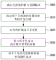
Fig. 8 illustrates a prediction method based on inter-component reference in an embodiment to which the present disclosure is applied.
According to the component type, the current block may be divided into a luminance block and a chrominance block. The chroma block may be predicted using pixels of the reconstructed luma block. This is called inter-component reference. In this embodiment, it is assumed that the size of a chroma block is (nTbW × nTbH), and the size of a luminance block corresponding to the chroma block is (2 × nTbW × 2 × nTbH). This assumes a case where the length ratio of the width and height between the luminance block and the chrominance block is 2:1, but even if one of the width and height is 1:1 and the other is 2:1, or both are 1:1, the examples described below can be applied identically or similarly.
Referring to fig. 8, an intra prediction mode of a chrominance block may be determined (S800).
In particular, predefined intra prediction modes for chroma blocks may be divided into a first group and a second group. Here, the first group may be configured as a prediction mode based on inter-component reference, and the second group may be configured as a predefined intra prediction mode for a luminance block. The encoding/decoding apparatus may define at least one of the INTRA _ LT _ CCLM, the INTRA _ L _ CCLM, or the INTRA _ T _ CCLM as a prediction mode based on the inter-component reference.
The intra prediction mode of the chroma block may be derived by selectively using one of the first group or the second group. The selection may be performed based on a predetermined first marker. The first flag may indicate an intra prediction mode in which the chroma block is derived based on the first group or the second group.
For example, when the first flag is a first value, the intra prediction mode of the chroma block may be determined to be one of one or more inter-component reference-based prediction modes belonging to the first group. For this purpose, an index specifying any one of the inter-component reference based prediction modes belonging to the first group may be used. The prediction modes based on the inter-component reference belonging to the first group and the index assigned to each prediction mode are shown in table 1 below.
[ Table 1]
| Idx | Prediction mode based on inter-component reference |
| 0 | INTRA_LT_CCLM |
| 1 | |
| 2 | INTRA_T_CCLM |
Table 1 is merely an example of an index assigned to each prediction mode, and is not limited thereto. That is, as shown in table 1, the indexes may be allocated in the order of priority of INTRA _ LT _ CCLM, INTRA _ L _ CCLM, INTRA _ T _ CCLM, or may be allocated in the order of priority of INTRA _ LT _ CCLM, INTRA _ T _ CCLM, INTRA _ L _ CCLM. Alternatively, the INTRA _ LT _ CCLM may have a lower priority order than the INTRA _ T _ CCLM or the INTRA _ L _ CCLM.
The first flag may be selectively signaled based on information indicating whether inter-component referencing is allowed. For example, if the value of the information is 1, the first flag may be signaled, otherwise, the first flag may not be signaled. Here, the information may be determined to be 0 or 1 based on a predetermined condition to be described later.
(condition 1) when the second flag indicating whether prediction based on inter-component reference is allowed is 0, information may be set to 0. The second flag may be signaled in at least one of a Video Parameter Set (VPS), a Sequence Parameter Set (SPS), a Picture Parameter Set (PPS), or a slice header.
(condition 2) when at least one of the following sub-conditions is satisfied, the information may be set to 1.
-value of 0 for-qtbtt _ dual _ tree _ intra _ flag
-the slice type is not an I-slice
-the size of the coding tree block is smaller than 64 x 64
In condition 2, qtbtt _ dual _ tree _ intra _ flag may indicate whether a coding tree block is implicitly divided into 64 × 64 coding blocks and the 64 × 64 coding blocks are divided based on a dual tree. The dual tree may refer to a method in which a luminance component and a chrominance component are divided in an independent division structure. The Size of the coding tree block (CtbLog2Size) may be a predefined Size in the encoding/decoding apparatus (e.g., 64 × 64, 128 × 128, 256 × 256), or may be encoded and signaled by the encoding apparatus.
(condition 3) when at least one of the following sub-conditions is satisfied, the information may be set to 1.
The width and height of the first upper block is 64
The depth of the first top block is the same as (CtbLog2Size-6), the first top block is divided based on the horizontal BT, and the second top block is 64 × 32
The depth of the first top piece is greater than (CtbLog2Size-6)
The depth of the first top block is the same as (CtbLog2Size-6), the first top block is divided based on horizontal BT and the second top block is divided based on vertical BT
In condition 3, the first upper block may be a block including the current chroma block as the lower block. For example, when the depth of the current chroma block is k, the depth of the first upper block is (k-n), and n may be 1, 2, 3, 4, or more. The depth of the first upper block may mean only a depth according to a partition based on a quadtree, or may mean a depth according to a partition of at least one of a quadtree, a binary tree, or a ternary tree. The second upper block is a lower block belonging to the first upper block, and may have a depth smaller than the current chroma block and a depth larger than the first upper block. For example, when the depth of the current chroma block is k, the depth of the second upper block is (k-m), and m may be a natural number less than n.
When all of the above-described conditions 1 to 3 are not satisfied, this information may be set to 0.
However, even in the case where at least one of the conditions 1 to 3 is satisfied, the information may be reset to 0 when at least one of the following sub-conditions is satisfied.
The first upper block is 64 x 64 and the sub-block unit prediction is performed
-at least one of the width or height of the first top piece is less than 64 and the depth of the first top piece is equal to (CtbLog2Size-6)
On the other hand, when the flag is the second value, the intra prediction mode (intra _ chroma _ pred _ mode) of the chroma block can be found based on information signaled by the encoding apparatus as shown in table 2 below.
[ Table 2]

According to table 2, the intra prediction mode of the chrominance block may be determined based on the signaled information and the intra prediction mode of the luminance block. In table 2, the mode 66 may mean a diagonal mode in the upper right direction, the mode 50 may mean a vertical mode, the mode 18 may mean a horizontal mode, and the mode 1 may mean a DC mode. For example, when the value of the signaled information intra _ chroma _ pred _ mode is 4, the intra prediction mode of the chroma block may be set to be the same as the intra prediction mode of the luma block. When the intra prediction mode of the chrominance block is derived from the second group, the chrominance block may be predicted by the intra prediction method according to fig. 6, and a detailed description will be omitted. Referring to fig. 8, a luminance region for inter-component reference of a chrominance block may be designated (S810).
The luminance region may include at least one of a luminance block or a neighboring region adjacent to the luminance block. Here, the luminance block may be defined as a region including pixels pY [ x ] [ y ] (x ═ 0.. nTbW × 2-1, y ═ 0.. nTbH × 2-1). A pixel may mean a reconstructed value before an in-loop (in-loop) filter is applied.
The neighborhood may include at least one of a left neighborhood, an upper neighborhood, or an upper left neighborhood. The left neighboring region may be set to a region including the pixel pY [ x ] [ y ] (x-1. -3, y-0.. 2 × numSampL-1). This setting can be performed only when the value of numSampL is greater than 0. The upper neighboring region may be set to a region including the pixel pY [ x ] [ y ] (x ═ 0..2 × nummapt-1, y ═ 1. -3). This setting can be performed only when the value of numSampT is greater than 0. The upper left neighboring region may be set as a region including the pixel pY [ x ] [ y ] (x ═ 1, y ═ 1, -2). This setting can be performed only when the upper left area of the luminance block is available.
The above-described numSampL and numSampT may be determined based on an intra prediction mode of the current block, which may mean a chroma block here.
For example, when the INTRA prediction mode of the current block is INTRA _ LT _ CCLM, numSampL and numSampT may be derived based on equation 1. Here, the INTRA _ LT _ CCLM may mean a mode in which inter-component reference is performed based on a left neighboring area and an upper neighboring area of the current block.
[ equation 1]
numSampT=availTnTbW:0
numSampL=availLnTbH:0
According to equation 1, numSampT is derived as nTbW when an upper neighbor region of the current block is available. Otherwise, numSampT may be derived as 0. Similarly, numSampL is derived as nTbH when the left neighbor region of the current block is available. Otherwise, numSampT may be derived as 0.
In contrast, when the INTRA prediction mode of the current block is not INTRA _ LT _ CCLM, numSampL and numSampT may be derived based on the following equation 2.
[ equation 2]
numSampT=(availT&&predModeIntra==INTRA_T_CCLM)?(nTbW+nu mTopRight):0
numSampL=(availL&&predModeIntra==INTRA_L_CCLM)?(nTbH+nu mLeftBelow):0
In equation 2, INTRA _ T _ CCLM may refer to a mode in which inter-component reference is performed based on an upper neighboring area of the current block. INTRA _ L _ CCLM may mean a mode in which inter-component reference is performed based on a left-adjacent region of the current block. numTopRight may mean the number of all or some pixels belonging to the upper right neighboring area of the chroma block. Some pixels may refer to available pixels among pixels belonging to the lowest pixel row of the corresponding region. In the availability determination, whether or not a pixel is available may be sequentially determined in a left-to-right direction. This process may be performed until an unavailable pixel is found. numLeftBelow may mean the number of all or some pixels belonging to the lower-left neighboring region of the chroma block. Some pixels may refer to available pixels among pixels belonging to the rightmost pixel row (column) of the corresponding region. In the availability determination, whether or not a pixel is available may be sequentially determined in a top-down direction. This process may be performed until an unavailable pixel is found.
Referring to fig. 8, downsampling may be performed on the luminance area designated in S810 (S820).
The down-sampling may comprise at least one of: 1. downsampling a luminance block; 2. down-sampling of the left neighboring region of the luminance block; or 3. downsampling of the upper neighborhood of the luminance block. This will be described in detail below.
1. Downsampling of luminance blocks
(embodiment mode 1)
The pixel pDsY [ x ] [ y ] (x ═ 0.. nTbW-1, y ═ 0.. nTbH-1) of the downsampled luminance block can be derived based on the corresponding pixel pY [2 × ] [2 × y ] and neighboring pixels of the luminance block. The adjacent pixel may mean at least one of a left adjacent pixel, a right adjacent pixel, an upper adjacent pixel, or a lower adjacent pixel of the corresponding pixel. For example, the pixel pDsY [ x ] [ y ] can be derived based on the following equation 3.
[ equation 3]
pDsY[x][y]=(pY[2*x][2*y-1]+pY[2*x-1][2*y]+4*pY[2*x][2*y]+pY[2*x+1][2*y]+pY[2*x][2*y+1]+4)>>3
However, there may be a case where a left neighboring area/upper neighboring area of the current block is unavailable. When the left neighboring region of the current block is not available, a pixel pDsY [0] [ y ] (y ═ 1.. nTbH-1) of the downsampled luminance block may be derived based on a corresponding pixel pY [0] [2 × y ] of the luminance block and neighboring pixels of the corresponding pixel. The neighboring pixels may mean at least one of upper neighboring pixels or lower neighboring pixels of the corresponding pixel. For example, a pixel pDsY [0] [ y ] (y 1.. nTbH-1) may be derived based on the following equation 4.
[ equation 4]
pDsY[0][y]=(pY[0][2*y-1]+2*pY[0][2*y]+pY[0][2*y+1]+2)>>2
When the upper neighboring area of the current block is not available, a pixel pDsY [ x ] [0] (x ═ 1.. nTbW-1) of the downsampled luminance block may be derived based on the corresponding pixel pY [2 × x ] [0] of the luminance block and neighboring pixels of the corresponding pixel. The neighboring pixels may mean at least one of left neighboring pixels or right neighboring pixels of the corresponding pixel. For example, the pixel pDsY [ x ] [0] (x ═ 1.. nTbW-1) can be derived based on the following equation 5.
[ equation 5]
pDsY[x][0]=(pY[2*x-1][0]+2*pY[2*x][0]+pY[2*x+1][0]+2)>>2
The pixel pDsY [0] [0] of the downsampled luminance block may be derived based on the corresponding pixel pY [0] [0] of the luminance block and/or neighboring pixels of the corresponding pixel. The positions of the neighboring pixels may vary depending on whether a left neighboring area/upper neighboring area of the current block is available.
For example, when the left neighboring region is available and the upper neighboring region is not available, pDsY [0] [0] can be obtained based on the following equation 6.
[ equation 6]
pDsY[0][0]=(pY[-1][0]+2*pY[0][0]+pY[1][0]+2)>>2
In contrast, when the left neighboring region is not available and the upper neighboring region is available, pDsY [0] [0] can be obtained based on the following equation 7.
[ equation 7]
pDsY[0][0]=(pY[0][-1]+2*pY[0][0]+pY[0][1]+2)>>2
In another example, pDsY [0] [0] may be set to the corresponding pixel pY [0] [0] of the luma block when neither the left nor the top neighboring region is available.
(embodiment mode 2)
The pixel pDsY [ x ] [ y ] (x ═ 0.. nTbW-1, y ═ 0.. nTbH-1) of the downsampled luminance block can be derived based on the corresponding pixel pY [2 × ] [2 × y ] of the luminance block and the neighboring pixels of the corresponding pixel. The adjacent pixel may mean at least one of a lower adjacent pixel, a left adjacent pixel, a right adjacent pixel, a left lower adjacent pixel, or a right lower adjacent pixel of the corresponding pixel. For example, the pixel pDsY [ x ] [ y ] can be derived based on the following equation 8.
[ equation 8]
pDsY[x][y]=(pY[2*x-1][2*y]+pY[2*x-1][2*y+1]+2*pY[2*x][2*y]+2*pY[2*x][2*y+1]+pY[2*x+1][2*y]+pY[2*x+1][2*y+1]+4)>>3
However, when the left neighboring region of the current block is not available, the pixel pDsY [0] [ y ] (y 0.. nTbH-1) of the down-sampled luminance block may be derived based on the corresponding pixel pY [0] [2 × y ] of the luminance block and the lower neighboring pixel of the corresponding pixel. For example, a pixel pDsY [0] [ y ] (y 0.. nTbH-1) may be derived based on the following equation 9.
[ equation 9]
pDsY[0][y]=(pY[0][2*y]+pY[0][2*y+1]+1)>>1
Downsampling of luminance blocks may be performed based on one of embodiment 1 and embodiment 2 described above. Here, one of embodiment 1 and embodiment 2 may be selected based on a predetermined flag. The flag may indicate whether the downsampled luminance pixel has the same position as that of the original luminance pixel. For example, when labeled as a first value, the downsampled luma pixel has the same position as the original luma pixel. Conversely, when the flag is a second value, the down-sampled luminance pixel has the same position in the horizontal direction as the original luminance pixel, but has a position shifted by one-half pixel in the vertical direction.
2. Downsampling of left neighboring regions of luminance blocks
(embodiment mode 1)
A pixel pfeftsy [ y ] (y 0.. numsamppl-1) of the downsampled left neighboring region may be derived based on the corresponding pixel pY [ -2] [2 × y ] of the left neighboring region and neighboring pixels of the corresponding pixel. The adjacent pixel may mean at least one of a left adjacent pixel, a right adjacent pixel, an upper adjacent pixel, or a lower adjacent pixel of the corresponding pixel. For example, the pixel pfifdsy [ y ] can be derived based on the following equation 10.
[ equation 10]
pLeftDsY[y]=(pY[-2][2*y-1]+pY[-3][2*y]+4*pY[-2][2*y]+pY[-1][2*y]+pY[-2][2*y+1]+4)>>3
However, when the upper-left neighbor of the current block is not available, the pixel pLeftDsY [0] of the downsampled left neighbor may be derived based on the corresponding pixel pY [ -2] [0] of the left neighbor and the neighbor pixels of the corresponding pixel. The neighboring pixels may mean at least one of left neighboring pixels or right neighboring pixels of the corresponding pixel. For example, the pixel pLeftDsY [0] can be derived based on the following equation 11.
[ equation 11]
pLeftDsY[0]=(pY[-3][0]+2*pY[-2][0]+pY[-1][0]+2)>>2
(embodiment mode 2)
A pixel pfeftsy [ y ] (y 0.. numsamppl-1) of the downsampled left neighboring region may be derived based on the corresponding pixel pY [ -2] [2 × y ] of the left neighboring region and neighboring pixels around the corresponding pixel. The adjacent pixel may mean at least one of a lower adjacent pixel, a left adjacent pixel, a right adjacent pixel, a left lower adjacent pixel, or a right lower adjacent pixel of the corresponding pixel. For example, the pixel pfifdsy [ y ] may be derived based on the following equation 12.
[ equation 12]
pLeftDsY[y]=(pY[-1][2*y]+pY[-1][2*y+1]+2*pY[-2][2*y]+2*pY[-2][2*y+1]+pY[-3][2*y]+pY[-3][2*y+1]+4)>>3
Similarly, the down-sampling of the left neighboring area may be performed based on one of embodiment 1 and embodiment 2 as described above. Here, one of embodiment 1 and embodiment 2 may be selected based on a predetermined flag. The flag indicates whether the down-sampled luminance pixel has the same position as that of the original luminance pixel. This is the same as described above.
Downsampling of the left neighboring area can be performed only when the numSampL value is greater than 0. When the numSampL value is greater than 0, this may mean that a left neighboring region of the current block is available, and the INTRA prediction mode of the current block is INTRA _ LT _ CCLM or INTRA _ L _ CCLM.
3. Downsampling of upper neighboring regions of a luminance block
(embodiment mode 1)
The pixel pTopDsY [ x ] (x ═ 0.. nummapt-1) of the downsampled up-neighboring region may be derived in consideration of whether the up-neighboring region belongs to a CTU different from the CTU to which the luminance block belongs.
When the upper neighboring region belongs to the same CTU as the luminance block, a pixel pTopDsY [ x ] of the downsampled upper neighboring region may be derived based on the corresponding pixel pY [2 x ] [ -2] of the upper neighboring region and neighboring pixels of the corresponding pixel. The adjacent pixel may mean at least one of a left adjacent pixel, a right adjacent pixel, an upper adjacent pixel, or a lower adjacent pixel of the corresponding pixel. For example, the pixel pTopDsY [ x ] can be derived based on the following equation 13.
[ equation 13]
pTopDsY[x]=(pY[2*x][-3]+pY[2*x-1][-2]+4*pY[2*x][-2]+pY[2*x+1][-2]+pY[2*x][-1]+4)>>3
In contrast, when the upper neighboring region belongs to a CTU different from the luminance block, the pixel pTopDsY [ x ] of the downsampled upper neighboring region may be derived based on the corresponding pixel pY [2 x ] [ -1] of the upper neighboring region and the neighboring pixels of the corresponding pixel. The neighboring pixels may mean at least one of left neighboring pixels or right neighboring pixels of the corresponding pixel. For example, the pixel pTopDsY [ x ] can be derived based on the following equation 14.
[ equation 14]
pTopDsY[x]=(pY[2*x-1][-1]+2*pY[2*x][-1]+pY[2*x+1][-1]+2)>>2
Alternatively, when the upper-left neighboring region of the current block is unavailable, the neighboring pixels may mean at least one of upper neighboring pixels or lower neighboring pixels of the corresponding pixels. For example, the pixel pTopDsY [0] can be derived based on the following equation 15.
[ equation 15]
pTopDsY[0]=(pY[0][-3]+2*pY[0][-2]+pY[0][-1]+2)>>2
Alternatively, when an upper-left neighboring region of the current block is unavailable and the upper neighboring region belongs to a CTU different from the luminance block, the pixel pTopDsY [0] may be set as the pixel pY [0] [ -1] of the upper neighboring region.
(embodiment mode 2)
A pixel pTopDsY [ x ] (x ═ 0.. numconstructed-1) of the downsampled upper neighboring region may be derived in consideration of whether the upper neighboring region belongs to a CTU different from the luminance block.
When the upper neighboring region belongs to the same CTU as the luminance block, a pixel pTopDsY [ x ] of the downsampled upper neighboring region may be derived based on the corresponding pixel pY [2 x ] [ -2] of the upper neighboring region and neighboring pixels of the corresponding pixel. The adjacent pixel may mean at least one of a lower adjacent pixel, a left adjacent pixel, a right adjacent pixel, a left lower adjacent pixel, or a right lower adjacent pixel of the corresponding pixel. For example, the pixel pTopDsY [ x ] can be derived based on the following equation 16.
[ equation 16]
pTopDsY[x]=(pY[2*x-1][-2]+pY[2*x-1][-1]+2*pY[2*x][-2]+2*pY[2*x][-1]+pY[2*x+1][-2]+pY[2*x+1][-1]+4)>>3
In contrast, when the upper neighboring region belongs to a CTU different from the luminance block, the pixel pTopDsY [ x ] of the downsampled upper neighboring region may be derived based on the corresponding pixel pY [2 x ] [ -1] of the upper neighboring region and the neighboring pixels of the corresponding pixel. The neighboring pixels may mean at least one of left neighboring pixels or right neighboring pixels of the corresponding pixel. For example, the pixel pTopDsY [ x ] can be derived based on the following equation 17.
[ equation 17]
pTopDsY[x]=(pY[2*x-1][-1]+2*pY[2*x][-1]+pY[2*x+1][-1]+2)>>2
Alternatively, when the upper-left neighboring region of the current block is unavailable, the neighboring pixels may mean at least one of upper neighboring pixels or lower neighboring pixels of the corresponding pixels. For example, the pixel pTopDsY [0] can be derived based on the following equation 18.
[ equation 18]
pTopDsY[0]=(pY[0][-2]+pY[0][-1]+1)>>1
Alternatively, when an upper-left neighboring region of the current block is unavailable and the upper neighboring region belongs to a CTU different from the luminance block, the pixel pTopDsY [0] may be set as the pixel pY [0] [ -1] of the upper neighboring region.
In a similar manner, the down-sampling of the upper neighborhood region may be performed based on one of embodiment 1 and embodiment 2 as described above. Here, one of embodiment 1 and embodiment 2 may be selected based on a predetermined flag. The flag indicates whether the down-sampled luminance pixel has the same position as that of the original luminance pixel. This is the same as described above.
In one example, downsampling of the upper neighbor region may be performed only when the numSampT value is greater than 0. When the numSampT value is greater than 0, this may mean that an upper neighboring area of the current block is available, and the INTRA prediction mode of the current block is INTRA _ LT _ CCLM or INTRA _ T _ CCLM.
Referring to fig. 8, parameters for inter-component reference of a chrominance block may be derived (S830).
The parameter may include at least one of a weight or an offset. The parameter may be determined in consideration of an intra prediction mode of the current block. The parameter may be derived using at least one of pixels of a luminance region or pixels of an upper/left neighboring region of the chrominance block. Here, the luminance region may include at least one of a luminance block or an upper/left neighboring region of the luminance block. The luminance area may mean an area to which the above-mentioned down-sampling is applied.
The parameters may be derived using all or some of the pixels belonging to the neighborhood of the luminance block and the chrominance block.
Some pixels in the luminance region may be specified, and some pixels in the chrominance block may be determined as pixels at positions corresponding to some pixels in the specified luminance region (embodiment 1). Some pixels in the luminance region may be extracted from the upper and left neighboring regions of the luminance block, respectively. The number of some pixels extracted from the upper neighboring region (numSampT) may be equal to the number of some pixels extracted from the left neighboring region (numSampL), or may be different from each other according to the size/shape of the luma block. For example, in a N × M luma block, numSampT is greater than numSampL when N is greater than M, and numSampT may be set to be less than numSampL when N is less than M. Alternatively, when the size of the luma block is smaller than a predetermined threshold size, at least one of numSampT or numSampL is determined as i, and i may be a natural number of 2, 3, 4, or more. In contrast, when the size of the luma block is greater than the predetermined threshold size, at least one of nummapt or nummapl is determined as j, and j may be a natural number greater than i (e.g., 3, 4, 5). Alternatively, some pixels may be extracted only from the upper neighboring region of the luminance block, or may be extracted only from the left neighboring region. Even in this case, as described above, numSampT or numSampL can be determined according to the size/shape of the luminance block. The positions of some of the pixels may be positions previously submitted to the encoding/decoding apparatus. For example, when the upper neighboring region of the luminance block is composed of 8 pixels, some pixels may be determined as at least one of four odd-numbered pixels from left to right or at least one of four even-numbered pixels. Alternatively, some pixels may include at least one of two odd-numbered pixels from left to right, and at least one of two even-numbered pixels from right to left. When each of the upper neighboring region/left neighboring region of the luminance block is composed of four pixels, some pixels may extract one or two pixels from the upper neighboring region/left neighboring region, respectively. In this case, in the upper neighboring region, at least one of two odd-numbered pixels or at least one of two even-numbered pixels may be determined. Alternatively, in the upper neighboring region, at least one of the first two pixels and the last two pixels may be determined. Some pixels may be extracted in the left adjacent region in the same manner.
Alternatively, instead, some pixels in the neighborhood of the chroma block may be specified, and some pixels in the luminance region may be determined as pixels at positions corresponding to some pixels in the neighborhood of the chroma block (embodiment 2). Here, some pixels in the neighboring area of the chrominance block may be determined according to the above-described method of determining some pixels of the luminance area, and redundant description will be omitted.
The maximum and minimum values from some of the extracted pixels may be calculated for the luminance region and the chrominance region, respectively. The maximum value and the minimum value may be determined as a maximum value and a minimum value in a plurality of some pixels, respectively. Alternatively, the plurality of pixels may be arranged in a descending order by size comparison between the plurality of pixels. In this case, the average value between the higher t pixels may be set to the maximum value, and the average value between the lower t pixels may be set to the minimum value. t may be a natural number of 1, 2, 3, or more.
Based on the calculated maximum and minimum values, a weight and/or offset of the parameter may be derived.
The chrominance block may be predicted based on the downsampled luminance block and the parameter (S840).
The chroma block may be predicted by applying at least one of a pre-derived weight or an offset to pixels of the downsampled luma block.
There may be various methods of performing prediction, and a method of performing prediction based on spatial correlation or temporal correlation may be an example.
As an example based on spatial correlation, methods such as extrapolation, interpolation, averaging, and duplication may be used using pre-encoded/decoded pixels in an area adjacent to the target block. Alternatively, a method such as block matching or template matching may be used in the reference region that has already been encoded/decoded. In this case, the reference region may be limited to the current picture.
As an example based on temporal correlation, a method of block matching or template matching may be used in the reference region being precoded/decoded. In this case, the reference region may be limited to other pictures.
In general, prediction may be performed based on correlation, but in the case of the above example, prediction may be classified according to a reference region (current picture/other picture). In this way, predictions can be distinguished not only by reference regions but also by various factors. For example, a reference region, a reference position, and a prediction method may be examples.
A case will be described in which prediction as one or more candidates is defined by the above various factors and prediction is performed based on the prediction.
The following describes a case in which prediction is divided into a plurality of candidates by different factors when the reference area is limited (the current picture in this example). In detail, it is assumed that prediction is performed based on spatial correlation and both of the following are classified as candidates according to a prediction method. Of course, the present invention is not limited thereto, and a modification example in which additional candidates are supported or elements for classifying predictions are differently configured is also possible.
1) Performing prediction by extrapolating, interpolating or averaging data in neighboring regions
2) Performing prediction by block matching in a pre-encoding/decoding region
Here, in the method 1, predetermined directional patterns, non-directional patterns, and the like may be configured as a prediction mode candidate group, and at least one of them may be selected to represent prediction mode information. In the method 2, the prediction mode information may be represented by motion vector information, reference picture information, or the like.
Each of the prediction methods may be activated by information indicating whether or not explicitly supported, or may implicitly determine whether or not supported. In this example, it is assumed that method 1 is implicitly activated (supported), and method 2 is explicitly activated by information indicating whether or not supported.
In order to predict the target block, prediction may be performed using one of prediction methods, and selection information may be generated. Further, according to the selected prediction method, subsequent prediction information (e.g., prediction mode information) may be generated, and various flags (syntax) may be configured therefor. Hereinafter, a method of determining a prediction method will be described in detail with reference to fig. 9 to 12. The unit (current block) to which the examples described below are applied may be one of a coding unit, a prediction unit, or a transform unit.
Referring to fig. 9, when the prediction method selection information (prediction _ mode _ flag) is checked and when one of the methods 1 or 2 is selected accordingly, the prediction mode information (intra _ mode _ information or motion _ information) is checked accordingly, and prediction may be performed based on the prediction method and the prediction mode information.
The intra _ mode _ information refers to prediction modes of extrapolation, interpolation, and averaging. Like intra _ predictor _ mode, the entire prediction mode can be configured and selected among a candidate set. Alternatively, the entire prediction mode may be configured into a plurality of candidate groups by classification according to a predetermined criterion such as mpm _ flag, mpm _ idx, remaining _ mode, or the like. The selection of the candidate set and the selection in the selected candidate set may be available. Since the selection of the candidate group and the selection among the selected candidate group can be derived by the above-described examples, a detailed description thereof will be omitted.
The motion _ information may include at least one of: motion prediction mode (skip/merge/Adaptive Motion Vector Prediction (AMVP)), motion vector prediction information, motion disparity information, reference region selection information, motion model selection information, prediction direction information, or motion vector precision (or motion vector difference precision) information.
The motion vector prediction may be predicted from among motion vectors of blocks closest to the current block in left, up, left-up, right-up, and left-down directions in the current picture. The present invention is not limited thereto, and a motion vector of a block separated by a predetermined distance (m, n) in a horizontal direction or a vertical direction may also be used as a prediction value. Here, m and n may be integers of 4, 8, 16, or more, and m and n may be greater than or equal to the width and height of the minimum prediction unit (or coding unit, transform unit, etc.). That is, prediction may be made based on a motion vector of a block that is pre-coded/decoded before the current block. In this case, the motion vectors of blocks that are not the closest may be managed in a FIFO scheme according to the encoding order based on the current block.
In addition, in another picture, prediction may be made from among motion vectors of blocks located at the left, right, top, bottom, top left, top right, bottom left, bottom right, and center of a block corresponding to the current block. Alternatively, (c, d) having a default value may be used as a prediction value of the motion vector and may have a value of (0, 0), but is not limited thereto.
In the case of the motion model selection information, the candidates may be configured as a translational motion model or a non-translational motion model, and may be classified based on the number of motion vectors representing the motion of the current block (an integer of 1, 2, 3, or more), but is not limited thereto. In addition, the motion vector precision may be a power of 2, such as 1/4, 1/2, 1, 2, 4, etc., where the exponent may be an integer (1, 2, or greater) including 0 with a positive or negative sign.
Here, the prediction method selection information may be classified according to the prediction method. When the block matching method (method 2) is selected, information on general block matching (motion _ information) may be generated. Here, in order to check what the reference region (reference picture) is, the reference region may be configured to include the current picture in the reference picture list. That is, information such as ref _ idx is generated as before, but the current picture may be included in the list as a candidate group for ref _ idx.
The above description may be a description applied to a P picture or B picture type and may be similarly applied to an I picture type, but the above description may be omitted since information on a reference region may be implicitly determined in the case of an I picture type. For this reason, since the reference region belongs only to the current picture, information such as ref _ idx may be omitted and information identical or similar to the general block matching may be generated.
The prediction method selection information may be generated regardless of the type of image. That is, in the case of the I picture type, prediction method selection information may also be generated. That is, in the case of the I-picture type, block matching (ibc, intra block copy) can also be supported.
Referring to fig. 10, prediction method selection information (prediction _ mode _ flag _ a) may be checked, and accordingly, whether to refer to a current picture or another picture may be determined. If it is determined that another picture is referred to (yes, i.e., 1), the corresponding prediction mode information (motion _ info _ a) is checked. If it is determined that the current picture is referred to (no, i.e., 0), one of method 1 or method 2 may be selected. Depending on the selected candidate, the prediction mode information (intra _ mode _ information or motion _ info _ B) may be checked accordingly. The prediction may be performed based on a prediction method and prediction mode information.
Here, the prediction method selection information may be composed of a plurality of flags (conditional). In this example, one flag (predictor _ mode _ flag _ a) may be used to identify the reference region, and another flag (predictor _ mode _ flag _ B) may be used to identify the prediction method (when the reference region is restricted to the current picture). Here, prediction method selection information for another flag (predictor _ mode _ flag _ B) may be conditionally generated.
The above description may be a description applied to a P image type or a B image type, and since the reference region is limited to the current picture in the case of an I image type, the process of checking the prediction _ mode _ flag _ a may be omitted, and the process of immediately checking the prediction _ mode _ flag _ B may be started.
Here, in the configuration of information on the reference area, the motion _ info _ a and the motion _ info _ B may have a difference, and other configurations except for information to be described later may be the same or similar.
For example, in motion _ info _ a, the reference picture list is configured to have a different picture from the current picture to process the reference picture information, and in motion _ info _ B, information on the reference picture may be omitted.
Alternatively, in the motion _ info _ a, the forward direction or the backward direction may be configured as a candidate for the prediction direction information, and the prediction direction information may be omitted in the motion _ info _ B.
Alternatively, as the configuration of a block used for reference of motion vector prediction, motion _ info _ a may target a spatially adjacent block and a temporally adjacent block, and motion _ info _ B may target a spatially adjacent block, and the detailed configuration of the spatially adjacent blocks may be the same or may not be the same. In addition, the default values for motion vector prediction may be configured to be the same or different.
Alternatively, as a candidate configuration for the motion model selection information, motion _ info _ a has a motion model using 1 to 3 motion vectors as a candidate set, and motion _ info _ B has a motion model using one motion vector as a candidate set.
Alternatively, as a candidate configuration for the motion vector precision information, the range of exponents in the motion _ info _ a may include 0 for integers having positive or negative signs, and the range of exponents in the motion _ info _ B may include 0 for integers having positive signs.
The above examples describe some cases where the prediction method selection information takes precedence but the order can be changed. That is, after determining which method of method 1 or method 2 is used for prediction (prediction _ mode _ flag _ B), if method 2 is selected in method 1 and method 2, it may be determined whether to use the current picture or a different picture as a reference region (prediction _ mode _ flag _ a). In the P picture type or the B picture type, the order may be changed, and in the I picture type, a portion for selecting a reference region may be omitted.
Referring to fig. 11, prediction method selection information (predictor _ mode _ flag _ a, predictor _ mode _ flag _ B) may be checked, a reference region is determined as one of a current picture or another picture (predictor _ mode _ flag _ a), and one of method 1 or method 2 is determined to perform prediction (predictor _ mode _ flag _ B). In the case of the previous example, the prediction method selection information is conditionally checked, in which case it is checked that all prediction method selection information may be different.
When the reference area is a current picture and method 1 is selected according to the prediction method selection information, prediction mode information (intra _ mode _ information) corresponding to the reference area may be checked. If the reference region is a current picture and method 2 is selected, prediction mode information (motion _ info _ B) corresponding to the reference region may be checked. If the reference region is a different picture and method 2 is selected, prediction mode information (motion _ info _ a) corresponding to the reference region may be checked.
In the present example, in the case of motion _ info _ a and motion _ info _ B, similar settings as in the previous example are possible.
The above description may be a description applied to a P picture type or a B picture type, and in an I picture type, prediction method selection information (predictor _ mode _ flag _ a) for a reference region may be checked or described, excluding a subsequent portion.
Referring to fig. 12, prediction method selection information (prediction _ mode _ flag) may be checked. If the value of the prediction _ mode _ flag is 0, method 1 is selected and the prediction mode information (intra _ mode _ information) according to method 1 may be checked. If the value of the prediction _ mode _ flag is 1, method 2 of referring to the current picture is selected, and the prediction mode information (motion _ info _ B) according to method 2 may be checked. If the value of the prediction _ mode _ flag is 2, method 2 of referring to another picture is selected, and prediction mode information (motion _ info _ a) according to method 2 may be checked.
In this example, the prediction method selection information is processed as one marker, but two or more indexes for the marker may be defined.
The above description may be a description applied to a P picture type or a B picture type, and may not be applied to an I picture type. That is, in the I picture type, the prediction method selection information may have a value of 0 or 1, and in the P picture type or the B picture type, the prediction method selection information may have a value of 0, 1, or 2. In this example, candidates referring to the current picture are first placed under 0 and 1, and candidates referring to another picture are placed under 2 to prevent index reordering according to the image type. However, the present invention is not limited thereto, and the indexes may be allocated in different orders.
All or some of the prediction method selection information described above may be selectively signaled in consideration of block properties. Here, the block attribute may include whether at least one of a skip mode, an image type (slice type), a block size, a prediction type, or a partition type is applied. Here, the prediction type may be classified as: a first prediction type comprising intra prediction and/or block matching modes (ibc mode); a second prediction type comprising inter prediction; and a third prediction type including intra prediction, block matching mode, and inter prediction. In the block matching mode, the current block is predicted based on a pre-coded/decoded region, and the pre-coded/decoded region may mean a region specified by a predetermined block vector. The pre-encoding/decoding area may be an area belonging to a current picture to which the current block belongs. Inter prediction is similar to the block matching mode in that inter prediction is performed based on a reference region specified by a motion vector, but inter prediction is different in that inter prediction refers to a picture located in a different time zone from the current block.
For example, the prediction _ mode _ flag _ a, which is one of the prediction method selection information, may be signaled only when at least one of: when the current block is not encoded in the skip mode (condition 1); when the image type of the slice to which the current block belongs is not an I slice (condition 2); when the size of the current block is not 4 × 4 (condition 3); or when the prediction type is satisfied as the third prediction type (condition 4).
However, if the above condition is not satisfied, the prediction _ mode _ flag _ a may not be signaled. In this case, the prediction _ mode _ flag _ a may be derived based on at least one of a block size, a prediction type, or an image type in the decoding apparatus. For example, when the current block is 4 × 4, it can be derived that the prediction _ mode _ flag _ a is 1. Alternatively, when the prediction type for the current block is the first prediction type, it may be derived that the prediction _ mode _ flag _ a is 1. Alternatively, when the prediction type for the current block is the second prediction type, it may be derived that the prediction _ mode _ flag _ a is 0. Alternatively, if the picture type of the slice to which the current block belongs is an I slice, the prediction _ mode _ flag _ a may be derived as 1, and otherwise, the prediction _ mode _ flag _ a may be derived as 0.
Meanwhile, the prediction _ mode _ flag _ B, which is one of the prediction method selection information, may be signaled in consideration of whether at least one of a skip mode, a picture type, a block size, a prediction mode, a prediction type, or a partition type is applied.
For example, when the picture type of the slice to which the current block belongs is an I slice and the current block is not encoded in the skip mode, the prediction _ mode _ flag _ B may be signaled. Alternatively, when the picture type of the slice to which the current block belongs is not an I slice and the prediction mode of the current block is not intra prediction, the prediction _ mode _ flag _ B may be signaled. Alternatively, when the picture type of the slice to which the current block belongs is not an I-slice, the current block is 4 × 4, and the current block is not encoded in the skip mode, the prediction _ mode _ flag _ B may be signaled. Alternatively, the predictor _ mode _ flag _ B may be signaled only when at least one of the width or height of the current block is less than 64. The predictor _ mode _ flag _ B may be signaled only when the prediction type for the current block is not the second prediction type.
Meanwhile, if the above-described condition is not satisfied, the prediction _ mode _ flag _ B may not be signaled. In this case, the prediction _ mode _ flag _ B may be derived based on at least one of a block size, a prediction type, or a picture type in the decoding apparatus. For example, when the current block is 128 × 128, it can be derived that the prediction _ mode _ flag _ B is 0. Alternatively, when the prediction type for the current block is the second prediction type, it may be derived that the prediction _ mode _ flag _ B is 0. Alternatively, if the picture type of the slice to which the current block belongs is an I slice, the prediction _ mode _ flag _ B may be derived to be 0 or 1, and otherwise, the prediction _ mode _ flag _ B may be derived to be 0. Here, when the picture type of the slice to which the current block belongs is an I slice, the prediction _ mode _ flag _ B may be derived based on a flag indicating whether block matching is allowed. For example, it can be derived that the prediction _ mode _ flag _ B is the same value as the flag. The flag may be signaled in at least one of a video parameter set, a sequence parameter set, a picture parameter set, or a slice header.
A prediction method for the current block may be selected based on at least one of the embodiments shown in fig. 9 to 12, and when the selected prediction method is intra prediction, the intra prediction according to fig. 6 or 8 may be performed.
For clarity of description, the exemplary methods of the present disclosure are represented as a series of operations, but are not intended to limit the order in which the steps are performed, and each step may be performed simultaneously or in a different order, if desired. To implement methods in accordance with the present disclosure, exemplary steps may include additional steps, may include other steps in addition to or in addition to some steps.
The various embodiments of the present disclosure are not intended to list all possible combinations, but are intended to describe representative aspects of the present disclosure, and events described in the various embodiments may be applied independently or may be applied in combinations of two or more.
In addition, various embodiments of the present disclosure may be implemented by hardware, firmware, software, or a combination thereof. For implementation by hardware, it may be implemented by one or more ASICs (application specific integrated circuits), DSPs (digital signal processors), DSPDs (digital signal processing devices), PLDs (programmable logic devices), FPGAs (field programmable gate arrays), general processors, controllers, micro-controllers, microprocessors, and the like.
The scope of the present disclosure includes: software or machine-executable instructions (e.g., operating systems, applications, firmware, programs, etc.) that cause operations of methods according to various embodiments to be executed on a device or computer, and non-transitory computer-readable media (non-transitory computer-readable media) that store such software or instructions, etc. and that are executable on a device or computer.
INDUSTRIAL APPLICABILITY
The present invention can be used for encoding/decoding a video signal.
Claims (7)
Priority Applications (8)
| Application Number | Priority Date | Filing Date | Title |
|---|---|---|---|
| CN202411273844.3A CN119011820A (en) | 2018-09-07 | 2019-09-06 | Method of encoding/decoding image and recording medium |
| CN202411273989.3A CN118972558A (en) | 2018-09-07 | 2019-09-06 | Method for encoding/decoding image, recording medium, and bit stream transmission method |
| CN202411273789.8A CN118945319A (en) | 2018-09-07 | 2019-09-06 | Method and recording medium for encoding/decoding images |
| CN202411273919.8A CN118945321A (en) | 2018-09-07 | 2019-09-06 | Method and recording medium for encoding/decoding images |
| CN202410888519.1A CN118646868A (en) | 2018-09-07 | 2019-09-06 | Method for encoding/decoding an image and method for transmitting a bit stream |
| CN202410888486.0A CN118612425A (en) | 2018-09-07 | 2019-09-06 | Method for encoding/decoding an image and method for transmitting a bit stream |
| CN202410888659.9A CN118646869A (en) | 2018-09-07 | 2019-09-06 | Method for encoding/decoding an image and method for transmitting a bit stream |
| CN202411273878.2A CN118945320A (en) | 2018-09-07 | 2019-09-06 | Method and recording medium for encoding/decoding images |
Applications Claiming Priority (7)
| Application Number | Priority Date | Filing Date | Title |
|---|---|---|---|
| KR10-2018-0107250 | 2018-09-07 | ||
| KR20180107250 | 2018-09-07 | ||
| KR10-2018-0110815 | 2018-09-17 | ||
| KR20180110815 | 2018-09-17 | ||
| KR20180112528 | 2018-09-19 | ||
| KR10-2018-0112528 | 2018-09-19 | ||
| PCT/KR2019/011556 WO2020050685A1 (en) | 2018-09-07 | 2019-09-06 | Method and device for coding/decoding image using intra prediction |
Related Child Applications (8)
| Application Number | Title | Priority Date | Filing Date |
|---|---|---|---|
| CN202411273789.8A Division CN118945319A (en) | 2018-09-07 | 2019-09-06 | Method and recording medium for encoding/decoding images |
| CN202411273989.3A Division CN118972558A (en) | 2018-09-07 | 2019-09-06 | Method for encoding/decoding image, recording medium, and bit stream transmission method |
| CN202411273844.3A Division CN119011820A (en) | 2018-09-07 | 2019-09-06 | Method of encoding/decoding image and recording medium |
| CN202410888486.0A Division CN118612425A (en) | 2018-09-07 | 2019-09-06 | Method for encoding/decoding an image and method for transmitting a bit stream |
| CN202411273878.2A Division CN118945320A (en) | 2018-09-07 | 2019-09-06 | Method and recording medium for encoding/decoding images |
| CN202411273919.8A Division CN118945321A (en) | 2018-09-07 | 2019-09-06 | Method and recording medium for encoding/decoding images |
| CN202410888519.1A Division CN118646868A (en) | 2018-09-07 | 2019-09-06 | Method for encoding/decoding an image and method for transmitting a bit stream |
| CN202410888659.9A Division CN118646869A (en) | 2018-09-07 | 2019-09-06 | Method for encoding/decoding an image and method for transmitting a bit stream |
Publications (2)
| Publication Number | Publication Date |
|---|---|
| CN112740675A true CN112740675A (en) | 2021-04-30 |
| CN112740675B CN112740675B (en) | 2024-10-01 |
Family
ID=69722933
Family Applications (9)
| Application Number | Title | Priority Date | Filing Date |
|---|---|---|---|
| CN201980058354.2A Active CN112740675B (en) | 2018-09-07 | 2019-09-06 | Method and apparatus for encoding/decoding an image using intra prediction |
| CN202411273844.3A Pending CN119011820A (en) | 2018-09-07 | 2019-09-06 | Method of encoding/decoding image and recording medium |
| CN202411273989.3A Pending CN118972558A (en) | 2018-09-07 | 2019-09-06 | Method for encoding/decoding image, recording medium, and bit stream transmission method |
| CN202411273789.8A Pending CN118945319A (en) | 2018-09-07 | 2019-09-06 | Method and recording medium for encoding/decoding images |
| CN202410888659.9A Pending CN118646869A (en) | 2018-09-07 | 2019-09-06 | Method for encoding/decoding an image and method for transmitting a bit stream |
| CN202410888486.0A Pending CN118612425A (en) | 2018-09-07 | 2019-09-06 | Method for encoding/decoding an image and method for transmitting a bit stream |
| CN202411273878.2A Pending CN118945320A (en) | 2018-09-07 | 2019-09-06 | Method and recording medium for encoding/decoding images |
| CN202411273919.8A Pending CN118945321A (en) | 2018-09-07 | 2019-09-06 | Method and recording medium for encoding/decoding images |
| CN202410888519.1A Pending CN118646868A (en) | 2018-09-07 | 2019-09-06 | Method for encoding/decoding an image and method for transmitting a bit stream |
Family Applications After (8)
| Application Number | Title | Priority Date | Filing Date |
|---|---|---|---|
| CN202411273844.3A Pending CN119011820A (en) | 2018-09-07 | 2019-09-06 | Method of encoding/decoding image and recording medium |
| CN202411273989.3A Pending CN118972558A (en) | 2018-09-07 | 2019-09-06 | Method for encoding/decoding image, recording medium, and bit stream transmission method |
| CN202411273789.8A Pending CN118945319A (en) | 2018-09-07 | 2019-09-06 | Method and recording medium for encoding/decoding images |
| CN202410888659.9A Pending CN118646869A (en) | 2018-09-07 | 2019-09-06 | Method for encoding/decoding an image and method for transmitting a bit stream |
| CN202410888486.0A Pending CN118612425A (en) | 2018-09-07 | 2019-09-06 | Method for encoding/decoding an image and method for transmitting a bit stream |
| CN202411273878.2A Pending CN118945320A (en) | 2018-09-07 | 2019-09-06 | Method and recording medium for encoding/decoding images |
| CN202411273919.8A Pending CN118945321A (en) | 2018-09-07 | 2019-09-06 | Method and recording medium for encoding/decoding images |
| CN202410888519.1A Pending CN118646868A (en) | 2018-09-07 | 2019-09-06 | Method for encoding/decoding an image and method for transmitting a bit stream |
Country Status (12)
| Country | Link |
|---|---|
| US (6) | US11917195B2 (en) |
| EP (1) | EP3849183A4 (en) |
| JP (4) | JP2021536717A (en) |
| KR (2) | KR102892410B1 (en) |
| CN (9) | CN112740675B (en) |
| AU (7) | AU2019336894A1 (en) |
| CA (6) | CA3269539A1 (en) |
| MY (1) | MY207996A (en) |
| PH (1) | PH12021550487A1 (en) |
| SG (1) | SG11202101876RA (en) |
| WO (1) | WO2020050685A1 (en) |
| ZA (2) | ZA202101431B (en) |
Families Citing this family (15)
| Publication number | Priority date | Publication date | Assignee | Title |
|---|---|---|---|---|
| CA3269539A1 (en) * | 2018-09-07 | 2025-10-31 | B1 Institute Of Image Technology, Inc. | Method and device for coding/decoding image using intra prediction |
| WO2020071616A1 (en) * | 2018-10-04 | 2020-04-09 | 엘지전자 주식회사 | Cclm-based intra-prediction method and apparatus therefor |
| CN118741110A (en) * | 2018-12-17 | 2024-10-01 | 皇家飞利浦有限公司 | A video encoding/decoding method and device |
| CN109874011B (en) * | 2018-12-28 | 2020-06-09 | 杭州海康威视数字技术股份有限公司 | Encoding method, decoding method and device |
| MX2021007764A (en) | 2018-12-28 | 2021-08-05 | B1 Institute Image Technology Inc | VIDEO ENCODING/DECODING METHOD AND DEVICE BASED ON INTRA PREDICTION. |
| JP7534399B2 (en) | 2019-11-01 | 2024-08-14 | 北京字節跳動網絡技術有限公司 | Derivation of Linear Parameters in Cross-Component Video Coding. |
| US11930208B2 (en) | 2020-01-10 | 2024-03-12 | Tencent America LLC | Method and apparatus for signaling skip mode flag |
| CN115462081B (en) | 2020-04-18 | 2025-01-10 | 抖音视界有限公司 | Cross-component codec for 4:2:0 or 4:2:2 video |
| CN120475148A (en) | 2020-05-11 | 2025-08-12 | Lg 电子株式会社 | Image compilation method and device |
| WO2022108417A1 (en) * | 2020-11-23 | 2022-05-27 | 현대자동차주식회사 | Image encoding and decoding method and apparatus using sub-block unit intra prediction |
| WO2023122630A1 (en) * | 2021-12-21 | 2023-06-29 | Bytedance Inc. | Method, apparatus, and medium for video processing |
| KR20240134149A (en) * | 2022-01-04 | 2024-09-06 | 엘지전자 주식회사 | Video encoding/decoding method, method for transmitting bitstream, and recording medium storing bitstream |
| WO2024122880A1 (en) * | 2022-12-06 | 2024-06-13 | 현대자동차주식회사 | Video coding method and device for adaptively generating most probable mode (mpm) list |
| WO2024122886A1 (en) * | 2022-12-07 | 2024-06-13 | 현대자동차주식회사 | Method and device for video coding using adaptive template-based intra prediction mode derivation |
| WO2024237502A1 (en) * | 2023-05-16 | 2024-11-21 | 현대자동차주식회사 | Method for extrapolation-based intra prediction |
Citations (3)
| Publication number | Priority date | Publication date | Assignee | Title |
|---|---|---|---|---|
| WO2017176030A1 (en) * | 2016-04-06 | 2017-10-12 | 주식회사 케이티 | Method and apparatus for processing video signal |
| WO2017222326A1 (en) * | 2016-06-24 | 2017-12-28 | 주식회사 케이티 | Video signal processing method and device |
| KR20180011285A (en) * | 2011-12-14 | 2018-01-31 | 주식회사 스카이미디어테크 | Method of encoding intra mode by choosing most probable mode with high hit rate and apparatus for the same, and method of decoding and apparatus for the same |
Family Cites Families (13)
| Publication number | Priority date | Publication date | Assignee | Title |
|---|---|---|---|---|
| BR112013014374B8 (en) | 2011-09-13 | 2022-08-30 | Mediatek Singapore Pte Ltd | METHOD AND APPARATUS FOR INTRA MODE ENCODING IN HEVC |
| KR101611409B1 (en) | 2011-09-28 | 2016-04-14 | 한국전자통신연구원 | Method for encoding/decoding an intra prediction mode and apparatus for the same |
| ES2816567T3 (en) * | 2011-10-24 | 2021-04-05 | Innotive Ltd | Method and apparatus for decoding intra-prediction mode |
| US11463689B2 (en) * | 2015-06-18 | 2022-10-04 | Qualcomm Incorporated | Intra prediction and intra mode coding |
| US10547854B2 (en) * | 2016-05-13 | 2020-01-28 | Qualcomm Incorporated | Neighbor based signaling of intra prediction modes |
| CN116708776A (en) | 2016-07-18 | 2023-09-05 | 韩国电子通信研究院 | Image encoding/decoding method and device, and recording medium for storing bit stream |
| CN116684579A (en) * | 2016-08-03 | 2023-09-01 | 株式会社Kt | Method and apparatus for encoding and decoding video |
| US10506228B2 (en) * | 2016-10-04 | 2019-12-10 | Qualcomm Incorporated | Variable number of intra modes for video coding |
| US10856010B2 (en) * | 2017-09-08 | 2020-12-01 | FG Innovation Company Limited | Device and method for coding video data based on multiple reference lines |
| CN119922307A (en) * | 2018-06-18 | 2025-05-02 | 世宗大学校产学协力团 | Image decoding/encoding method and method for transmitting bit stream |
| US10893285B2 (en) * | 2018-06-29 | 2021-01-12 | FG Innovation Company Limited | Device and method for coding video data based on one or more reference lines |
| CA3269539A1 (en) | 2018-09-07 | 2025-10-31 | B1 Institute Of Image Technology, Inc. | Method and device for coding/decoding image using intra prediction |
| MX2021007764A (en) * | 2018-12-28 | 2021-08-05 | B1 Institute Image Technology Inc | VIDEO ENCODING/DECODING METHOD AND DEVICE BASED ON INTRA PREDICTION. |
-
2019
- 2019-09-06 CA CA3269539A patent/CA3269539A1/en active Pending
- 2019-09-06 CN CN201980058354.2A patent/CN112740675B/en active Active
- 2019-09-06 CN CN202411273844.3A patent/CN119011820A/en active Pending
- 2019-09-06 CN CN202411273989.3A patent/CN118972558A/en active Pending
- 2019-09-06 JP JP2021537422A patent/JP2021536717A/en active Pending
- 2019-09-06 CA CA3269536A patent/CA3269536A1/en active Pending
- 2019-09-06 CA CA3299504A patent/CA3299504A1/en active Pending
- 2019-09-06 CN CN202411273789.8A patent/CN118945319A/en active Pending
- 2019-09-06 EP EP19857599.5A patent/EP3849183A4/en active Pending
- 2019-09-06 CN CN202410888659.9A patent/CN118646869A/en active Pending
- 2019-09-06 SG SG11202101876RA patent/SG11202101876RA/en unknown
- 2019-09-06 CA CA3112916A patent/CA3112916A1/en active Pending
- 2019-09-06 KR KR1020190110644A patent/KR102892410B1/en active Active
- 2019-09-06 US US17/273,848 patent/US11917195B2/en active Active
- 2019-09-06 CA CA3299513A patent/CA3299513A1/en active Pending
- 2019-09-06 CA CA3299518A patent/CA3299518A1/en active Pending
- 2019-09-06 MY MYPI2021000976A patent/MY207996A/en unknown
- 2019-09-06 AU AU2019336894A patent/AU2019336894A1/en not_active Abandoned
- 2019-09-06 CN CN202410888486.0A patent/CN118612425A/en active Pending
- 2019-09-06 WO PCT/KR2019/011556 patent/WO2020050685A1/en not_active Ceased
- 2019-09-06 CN CN202411273878.2A patent/CN118945320A/en active Pending
- 2019-09-06 CN CN202411273919.8A patent/CN118945321A/en active Pending
- 2019-09-06 CN CN202410888519.1A patent/CN118646868A/en active Pending
-
2021
- 2021-03-02 ZA ZA2021/01431A patent/ZA202101431B/en unknown
- 2021-03-02 PH PH12021550487A patent/PH12021550487A1/en unknown
-
2022
- 2022-02-28 ZA ZA2022/02999A patent/ZA202202999B/en unknown
-
2023
- 2023-12-01 US US18/526,377 patent/US12184894B2/en active Active
-
2024
- 2024-01-29 JP JP2024010892A patent/JP7696463B2/en active Active
- 2024-06-26 US US18/754,969 patent/US12610080B2/en active Active
- 2024-06-26 US US18/754,981 patent/US20240348824A1/en active Pending
- 2024-06-26 US US18/754,945 patent/US12382096B2/en active Active
-
2025
- 2025-02-20 US US19/058,341 patent/US20250193441A1/en active Pending
- 2025-03-26 AU AU2025202199A patent/AU2025202199A1/en active Pending
- 2025-03-26 AU AU2025202196A patent/AU2025202196A1/en active Pending
- 2025-03-26 AU AU2025202195A patent/AU2025202195A1/en active Pending
- 2025-03-26 AU AU2025202197A patent/AU2025202197A1/en active Pending
- 2025-03-26 AU AU2025202193A patent/AU2025202193A1/en active Pending
- 2025-05-30 JP JP2025091078A patent/JP2025124790A/en active Pending
- 2025-07-08 AU AU2025205194A patent/AU2025205194A1/en active Pending
- 2025-11-25 KR KR1020250180111A patent/KR20250171235A/en active Pending
- 2025-12-11 JP JP2025245480A patent/JP2026041997A/en active Pending
Patent Citations (3)
| Publication number | Priority date | Publication date | Assignee | Title |
|---|---|---|---|---|
| KR20180011285A (en) * | 2011-12-14 | 2018-01-31 | 주식회사 스카이미디어테크 | Method of encoding intra mode by choosing most probable mode with high hit rate and apparatus for the same, and method of decoding and apparatus for the same |
| WO2017176030A1 (en) * | 2016-04-06 | 2017-10-12 | 주식회사 케이티 | Method and apparatus for processing video signal |
| WO2017222326A1 (en) * | 2016-06-24 | 2017-12-28 | 주식회사 케이티 | Video signal processing method and device |
Also Published As
Similar Documents
| Publication | Publication Date | Title |
|---|---|---|
| CN112740675B (en) | Method and apparatus for encoding/decoding an image using intra prediction | |
| US12096018B2 (en) | Method and apparatus for processing video signal | |
| CN109644281B (en) | Method and apparatus for processing video signals | |
| CN111937381A (en) | Image encoding/decoding method and apparatus using intra prediction | |
| HK40115839A (en) | Method of encoding/decoding an image and recording medium | |
| HK40114655A (en) | Method of encoding/decoding an image and recording medium | |
| HK40114287A (en) | Method of encoding/decoding an image and recording medium | |
| HK40114286A (en) | Method of encoding/decoding an image and recording medium | |
| HK40114289A (en) | Method of encoding/decoding an image and method of transmitting a bitstream | |
| HK40114291A (en) | Method of encoding/decoding an image and method of transmitting a bitstream | |
| HK40114290A (en) | Method of encoding/decoding an image and method of transmitting a bitstream | |
| HK40114285A (en) | Method of encoding/decoding an image, recording medium and bitstream transmitting method |
Legal Events
| Date | Code | Title | Description |
|---|---|---|---|
| PB01 | Publication | ||
| PB01 | Publication | ||
| SE01 | Entry into force of request for substantive examination | ||
| SE01 | Entry into force of request for substantive examination | ||
| GR01 | Patent grant | ||
| GR01 | Patent grant |