CN112692952B - A device for laying straw boards - Google Patents
A device for laying straw boards Download PDFInfo
- Publication number
- CN112692952B CN112692952B CN202011586607.4A CN202011586607A CN112692952B CN 112692952 B CN112692952 B CN 112692952B CN 202011586607 A CN202011586607 A CN 202011586607A CN 112692952 B CN112692952 B CN 112692952B
- Authority
- CN
- China
- Prior art keywords
- plate
- push
- conveyor
- push plate
- gantry
- Prior art date
- Legal status (The legal status is an assumption and is not a legal conclusion. Google has not performed a legal analysis and makes no representation as to the accuracy of the status listed.)
- Active
Links
- 239000010902 straw Substances 0.000 title claims abstract description 21
- 238000000227 grinding Methods 0.000 claims description 34
- 238000005192 partition Methods 0.000 claims description 25
- 238000007599 discharging Methods 0.000 claims description 21
- 230000000903 blocking effect Effects 0.000 claims description 13
- 238000003780 insertion Methods 0.000 claims description 6
- 230000037431 insertion Effects 0.000 claims description 6
- 238000004519 manufacturing process Methods 0.000 abstract description 6
- 239000000463 material Substances 0.000 abstract description 3
- 239000000843 powder Substances 0.000 description 61
- 238000010586 diagram Methods 0.000 description 6
- 230000000694 effects Effects 0.000 description 4
- 239000002994 raw material Substances 0.000 description 4
- 238000009826 distribution Methods 0.000 description 3
- 230000005484 gravity Effects 0.000 description 3
- 238000000034 method Methods 0.000 description 3
- 239000000853 adhesive Substances 0.000 description 2
- 238000004026 adhesive bonding Methods 0.000 description 2
- 230000001070 adhesive effect Effects 0.000 description 2
- 238000001035 drying Methods 0.000 description 2
- RNFJDJUURJAICM-UHFFFAOYSA-N 2,2,4,4,6,6-hexaphenoxy-1,3,5-triaza-2$l^{5},4$l^{5},6$l^{5}-triphosphacyclohexa-1,3,5-triene Chemical compound N=1P(OC=2C=CC=CC=2)(OC=2C=CC=CC=2)=NP(OC=2C=CC=CC=2)(OC=2C=CC=CC=2)=NP=1(OC=1C=CC=CC=1)OC1=CC=CC=C1 RNFJDJUURJAICM-UHFFFAOYSA-N 0.000 description 1
- 229920002522 Wood fibre Polymers 0.000 description 1
- 238000005054 agglomeration Methods 0.000 description 1
- 230000002776 aggregation Effects 0.000 description 1
- 230000009286 beneficial effect Effects 0.000 description 1
- 239000011094 fiberboard Substances 0.000 description 1
- 239000003063 flame retardant Substances 0.000 description 1
- 238000002156 mixing Methods 0.000 description 1
- 230000000149 penetrating effect Effects 0.000 description 1
- 238000003825 pressing Methods 0.000 description 1
- 238000004513 sizing Methods 0.000 description 1
- 239000002025 wood fiber Substances 0.000 description 1
Images


Classifications
-
- Y—GENERAL TAGGING OF NEW TECHNOLOGICAL DEVELOPMENTS; GENERAL TAGGING OF CROSS-SECTIONAL TECHNOLOGIES SPANNING OVER SEVERAL SECTIONS OF THE IPC; TECHNICAL SUBJECTS COVERED BY FORMER USPC CROSS-REFERENCE ART COLLECTIONS [XRACs] AND DIGESTS
- Y02—TECHNOLOGIES OR APPLICATIONS FOR MITIGATION OR ADAPTATION AGAINST CLIMATE CHANGE
- Y02P—CLIMATE CHANGE MITIGATION TECHNOLOGIES IN THE PRODUCTION OR PROCESSING OF GOODS
- Y02P60/00—Technologies relating to agriculture, livestock or agroalimentary industries
- Y02P60/20—Reduction of greenhouse gas [GHG] emissions in agriculture, e.g. CO2
Landscapes
- Jigging Conveyors (AREA)
- Feeding Of Articles To Conveyors (AREA)
Abstract
本发明涉及秸秆板材的生产设备领域,尤其涉及一种秸秆板的铺平装置。一种秸秆板的铺平装置,包括:输送机、支撑架、龙门架、电滚筒、移动支架、分料器、挡板;所述支撑架为两个,分别固定在输送机的两侧,分料器通过支撑架固定在输送机的上方,输送机的运行方向为从左向右运行;所述龙门架横跨并固定在输送机的上方;所述移动支架通过螺杆与龙门架的丝孔啮合安装在龙门架上;所述电滚筒安装在移动支架上。本发明解决现有秸秆经干燥后会有堆积成团,不方便铺装的问题。

The invention relates to the field of production equipment for straw boards, in particular to a device for laying straw boards. A straw board leveling device, comprising: a conveyor, a support frame, a gantry frame, an electric drum, a moving frame, a material distributor, and a baffle; the two support frames are respectively fixed on both sides of the conveyor, The distributor is fixed on the top of the conveyor through the support frame, and the running direction of the conveyor is from left to right; the gantry frame is spanned and fixed above the conveyor; The holes are engaged and installed on the gantry; the electric drum is installed on the moving bracket. The invention solves the problem that the existing straws will be piled up into clusters after being dried, which is inconvenient for paving.
Description
技术领域technical field
本发明涉及秸秆板材的生产设备领域,具体涉及一种秸秆板的铺平装置。The invention relates to the field of production equipment for straw boards, in particular to a device for leveling straw boards.
背景技术Background technique
秸秆板材生产时,需要对秸秆进行粉碎,粉碎后的秸秆原料风送至料仓,经输送计量施胶混合搅拌,胶黏剂使用高性能环保阻燃粘合剂,该粘合剂适用于一切非木质纤维类的胶合,特别是对不同农作物秸秆均具有相融的胶合作用。During the production of straw board, the straw needs to be pulverized, and the pulverized straw raw material is sent to the silo by air, and is mixed and stirred by conveying, measuring, sizing, and mixing. The adhesive uses a high-performance environmentally friendly flame-retardant adhesive. Gluing of non-wood fibers, especially for different crop straws, has a compatible gluing effect.
经混合好的秸秆原料进入专用秸秆铺平装置铺装,经板坯预压机预压初步成型,铺平装置是秸秆板材生产线上重要的生产设备,板坯成型结构和表面质量,横向密度误差大小是衡量纤维板质量好坏的重要指标。The mixed straw raw material enters the special straw paving device for paving, and is preliminarily formed by the slab pre-pressing machine. The paving device is an important production equipment on the straw board production line. The slab forming structure and surface quality, transverse density error Size is an important indicator to measure the quality of fiberboard.
现有的铺平装置结构简单,通常是在皮带机上方设置分料器,粉料经分料器下落至皮带上进行铺平,但粉碎后的秸秆经干燥后会有堆积成团现象,如直接铺装,在板坯上会出现高密度点,造成板坯的密度分布不均匀,另外在粉料摊铺过程中,不能有效的处理粉料的上、下表面,造成上、下表面凹凸不平,直接影响到加工出的秸秆板的质量。The structure of the existing leveling device is simple, usually a feeder is set above the belt conveyor, and the powder falls on the belt through the feeder for leveling, but the crushed straw will accumulate into agglomerates after drying, such as For direct paving, high-density spots will appear on the slab, resulting in uneven density distribution of the slab. In addition, in the process of powder paving, the upper and lower surfaces of the powder cannot be effectively treated, resulting in unevenness on the upper and lower surfaces. Unevenness directly affects the quality of the processed straw board.
发明内容SUMMARY OF THE INVENTION
因此,本发明正是鉴于以上问题而做出的,本发明通过分料器结构的设置,解决现有秸秆经干燥后会有堆积成团,不方便铺装的问题。本发明是通过以下技术方案实现上述目的:Therefore, the present invention is made in view of the above problems. The present invention solves the problem that the existing straws will pile up into clusters after drying, which is inconvenient for paving. The present invention realizes above-mentioned purpose through following technical scheme:
本发明提供一种秸秆板的铺平装置,包括:输送机、支撑架、龙门架、电滚筒、移动支架、分料器、挡板;The invention provides a device for laying straw boards, comprising: a conveyor, a support frame, a gantry frame, an electric drum, a moving frame, a distributor, and a baffle;
所述支撑架为两个,分别固定在输送机的两侧,分料器通过支撑架固定在输送机的上方,输送机的运行方向为从左向右运行,支撑架的左侧连接有横梁,横梁上固定有电机,电机位于横梁的左侧,横梁开有贯穿其左右侧面的推送孔;There are two supporting frames, which are respectively fixed on both sides of the conveyor. The distributor is fixed on the top of the conveyor through the supporting frame. The running direction of the conveyor is from left to right, and the left side of the supporting frame is connected with a beam. , a motor is fixed on the beam, the motor is located on the left side of the beam, and the beam is provided with a push hole running through its left and right sides;
所述分料器包括:输料部、出料部、推送组件,输料部、出料部均为中空结构,出料部连接在输料部的右侧,推送组件从输料部的左侧插入输料部的内部,输料部为“L”形,输料部的竖直部分上端为进料口,输料部的水平部分的顶板向右下方倾斜,输料部的内部设置有多个间隔相等的隔板,隔板位于输料部的拐角处并将输料部的内部分割成多个独立的输料通道,隔板位于输料部竖直部分的顶面为刀刃状,隔板的两板面均为粗糙的面,输料部的左侧板开有多个与多个输料通道位置一一对应的插孔;The distributor includes: a feeding part, a discharging part, and a pushing component. The feeding part and the discharging part are both hollow structures. The side is inserted into the inside of the feeding part, the feeding part is "L" shaped, the upper end of the vertical part of the feeding part is the feeding port, the top plate of the horizontal part of the feeding part is inclined downward to the right, and the interior of the feeding part is provided with A plurality of baffles with equal intervals, the baffles are located at the corners of the conveying part and divide the interior of the conveying part into multiple independent conveying channels; The two plate surfaces of the partition plate are rough surfaces, and the left plate of the feeding part is provided with a plurality of jacks corresponding to the positions of the feeding passages one-to-one;
所述出料部由减缩通道、平直通道组成,减缩通道的一端开口宽,另一端开口窄,出料部通过减缩通道宽的一端与输料部连通,减缩通道窄的一端与平直通道连通,平直通道的另一端为出料口;The discharge part is composed of a reduction channel and a straight channel. One end of the reduction channel has a wide opening and the other end has a narrow opening. The discharge part is connected to the conveying part through the wide end of the reduction channel, and the narrow end of the reduction channel is connected to the straight channel. Connected, the other end of the straight channel is the discharge port;
所述输料部、出料部的底面处于同一平面且均设置有多个间隔布置的半圆形凸条;所述推送组件包括:推板、连接板、推杆、连接销、连接杆、偏心轴、转盘二、摩擦条,推板为多个并一一对应的位于多个输料通道内,多个推板的左端均穿过各自对应的插孔延伸至输料部的外部并连接在连接板的右侧面上,推杆的一端垂直连接在连接板的左侧面上,另一端穿过横梁的推送孔并通过连接销旋转的与连接杆连接,连接杆旋转的与偏心轴连接,偏心轴偏心的连接在转盘二的下表面,转盘二同轴的与电机的电机轴连接;The bottom surfaces of the feeding part and the discharging part are on the same plane and are provided with a plurality of semicircular convex strips arranged at intervals; the pushing component includes: a push plate, a connecting plate, a push rod, a connecting pin, a connecting rod, The eccentric shaft, the second turntable, the friction strip, the push plates are located in a plurality of feeding channels in one-to-one correspondence, and the left ends of the plurality of push plates extend to the outside of the feeding part through the corresponding jacks and are connected to each other. On the right side of the connecting plate, one end of the push rod is vertically connected to the left side of the connecting plate, and the other end passes through the push hole of the beam and is connected to the connecting rod through the connecting pin to rotate, and the connecting rod rotates to the eccentric shaft The eccentric shaft is eccentrically connected to the lower surface of the second turntable, and the second turntable is coaxially connected to the motor shaft of the motor;
所述推板位于输料通道内时,推板与隔板的高度一致,推板包括:研磨板、推送板,研磨板连接在推送板的上表面,研磨板从上至下逐渐变厚且其顶端刀刃状,研磨板的两板面均为粗糙的面,当推板位于输料通道内时,研磨板与其相邻的两个隔板均不接触并各形成一上宽下窄的下落间隙;When the push plate is located in the conveying channel, the height of the push plate and the partition plate is the same, and the push plate includes: a grinding plate and a pushing plate, the grinding plate is connected to the upper surface of the pushing plate, and the grinding plate gradually thickens from top to bottom. Its top is blade-shaped, and both surfaces of the grinding plate are rough surfaces. When the push plate is located in the conveying channel, the grinding plate and its adjacent two partitions are not in contact and each forms a drop with a wide upper and a narrow lower. gap;
所述插孔与推板左端的相匹配,可避免推板往复运动时粉料从插孔中漏出;所述推送板的左侧面高于其右侧面,推送板的右侧面垂直于其底面,推送板的顶面由水平的面和倾斜的面组成,水平的面位于倾斜的面的左侧,当推板在输料通道内做往复运动时,推送板的水平的面始终与插孔的内壁面贴合,当推板在输料通道内做往复运动时,推送板的倾斜的面与输料部的顶板始终不接触,并在两者之间始终形成一倾斜的滑道;The jack is matched with the left end of the push plate, which can prevent the powder from leaking out of the jack when the push plate reciprocates; the left side of the push plate is higher than the right side, and the right side of the push plate is perpendicular to the hole. Its bottom surface, the top surface of the push plate is composed of a horizontal surface and an inclined surface, and the horizontal surface is located on the left side of the inclined surface. The inner wall surface of the jack is in contact with each other. When the push plate reciprocates in the conveying channel, the inclined surface of the push plate and the top plate of the conveying part are never in contact, and an inclined slideway is always formed between the two. ;
所述输料部的右侧内壁面上还设置有挡条,挡条的顶面为向左下方倾斜的面并高于隔板,挡条的下端延伸至输料通道内,挡条面向插孔的面开有多个与多个研磨板位置一一对应且形状相匹配的滑槽,当推板在输料通道内做往复运动时,研磨板的右端始终位于滑槽内,在推板做往复运动时,推板始终与推板不接触;The right inner wall surface of the feeding part is also provided with a blocking bar, the top surface of the blocking bar is a surface inclined downward to the left and higher than the partition plate, the lower end of the blocking bar extends into the conveying channel, and the blocking bar faces the insertion channel. The surface of the hole is provided with a plurality of chutes that correspond to the positions of the grinding plates and the shapes match. When the push plate reciprocates in the conveying channel, the right end of the grinding plate is always located in the chute. When doing reciprocating motion, the push plate is always out of contact with the push plate;
所述摩擦条为多根,多根摩擦条连接在连接板的下端,并水平的位于输料部、出料部的底面多个凸条的正下方,摩擦条的上表面设置有多个间隔布置的弹性小半圆形凸点;The friction strips are multiple, and the multiple friction strips are connected to the lower end of the connecting plate, and are horizontally positioned directly below the multiple protruding strips on the bottom surfaces of the feeding part and the discharging part, and the upper surface of the friction strips is provided with a plurality of intervals Arranged elastic small semi-circular bumps;
所述龙门架横跨并固定在输送机的上方,沿输送机运行的方向,龙门架位于分料器的下游,龙门架的横梁上开有贯穿其上下表面的丝孔,在丝孔的两侧还分别开有一个贯穿龙门架横梁的限位孔;The gantry spans and is fixed above the conveyor. Along the running direction of the conveyor, the gantry is located downstream of the feeder. The beam of the gantry is provided with wire holes running through its upper and lower surfaces. There is also a limit hole on the side that runs through the beam of the gantry;
所述移动支架的顶部中心处设置有螺杆,移动支架转动连接于螺杆的底端,移动支架通过螺杆与龙门架的丝孔啮合安装在龙门架上,螺杆的顶端安装有转盘一,移动支架的顶部还设置有两个与龙门架的限位孔位置相对应且尺寸相匹配的导杆,两个导杆分别穿过龙门架的两个限位孔;The top center of the movable bracket is provided with a screw rod, and the movable bracket is rotatably connected to the bottom end of the screw rod. The top is also provided with two guide rods corresponding to the position of the limit holes of the gantry frame and matched in size, and the two guide rods respectively pass through the two limit holes of the gantry frame;
所述电滚筒安装在移动支架上,电滚筒转动方向与输送机的转动方向相反,电滚筒的滚筒的表面上设有刷毛(图中未示出);所述挡板为两个,分别固定在龙门架的支撑腿上,挡板的底部与输送机上输送带的上带面相贴。The electric drum is installed on the moving bracket, the rotation direction of the electric drum is opposite to that of the conveyor, and the surface of the drum of the electric drum is provided with bristles (not shown in the figure); there are two baffles, which are respectively fixed On the support legs of the gantry, the bottom of the baffle is in contact with the upper belt surface of the conveyor belt on the conveyor.
本发明的有益效果:Beneficial effects of the present invention:
1、本发明通过利用隔板、研磨板刀刃状的顶端,使粉料在下落时与其撞击,部分成团的粉料将会散开,而未发生撞击的成团的粉料将落入下落间隙,由于下落间隙是上宽下窄的,成团的粉料在其上部粉料和自身的重力作用下,将被抵压在研磨板与隔板之间,在推板往复运动以及隔板、研磨板粗糙的板面作用下,成团的粉料将被揉搓散开并从下落间隙下落,下落的粉料通过倾斜的滑道下滑至推送板的右侧,并在推板往复运动的作用下,粉料被推送至出料部内部,同时在摩擦条与输料部、出料部的底板摩擦的作用下,输料部、出料部产生振动,使输料部中的粉料下落更加容易以及出料部中的粉料摊铺的更均匀。1. The present invention makes use of the baffle and the blade-shaped top of the grinding plate to make the powder collide with it when it falls, and part of the agglomerated powder will disperse, while the agglomerated powder that does not hit will fall into the drop. Gap, because the falling gap is wide at the top and narrow at the bottom, the agglomerated powder will be pressed between the grinding plate and the partition under the action of the upper powder and its own gravity, and the reciprocating motion of the push plate and the partition , Under the action of the rough surface of the grinding plate, the powder in agglomeration will be rubbed and scattered and fall from the falling gap. Under the action, the powder is pushed to the inside of the discharge part. At the same time, under the action of friction between the friction strip and the bottom plate of the conveying part and the discharging part, the conveying part and the discharging part vibrate, so that the powder in the conveying part vibrates. Falling is easier and the powder in the discharge section is spread more evenly.
2、本发明利用电滚筒上的刷毛,可以有效的将粉料上表面多余的粉料清扫并填补在凹陷处,提高了摊铺效果,在电滚筒对粉料摊铺的过程中,通过输送机两侧的挡板,可以有效避免粉料散落,节约原料,最终铺装在输送机上的板坯的上、下表面更加平整且密度分布更均匀。2. The present invention utilizes the brush bristles on the electric drum, which can effectively clean and fill the excess powder on the upper surface of the powder in the depressions, thereby improving the paving effect. The baffles on both sides of the machine can effectively avoid powder scattering and save raw materials. The upper and lower surfaces of the slabs finally paved on the conveyor are smoother and the density distribution is more uniform.
附图说明Description of drawings
图1为本发明的整体结构示意图。FIG. 1 is a schematic diagram of the overall structure of the present invention.
图2为本发明的支撑架的结构示意图。FIG. 2 is a schematic structural diagram of the support frame of the present invention.
图3为本发明的分料器的结构示意图。FIG. 3 is a schematic structural diagram of the distributor of the present invention.
图4为本发明的输料部的内部结构示意图。FIG. 4 is a schematic diagram of the internal structure of the feeding part of the present invention.
图5为本发明的推送组件的结构示意图。FIG. 5 is a schematic structural diagram of the push component of the present invention.
图6为本发明的推板的结构示意图。FIG. 6 is a schematic structural diagram of the push plate of the present invention.
图7为本发明的推板插入输料部内部的结构示意图。FIG. 7 is a schematic view of the structure of the push plate inserted into the conveying part according to the present invention.
其中,输送机-10、支撑架-20、横梁-21、电机-22、推送孔-23、龙门架-30、丝孔-31、限位孔-32、电滚筒-40、移动支架-50、螺杆-51、导杆-52、转盘一-53、分料器-60、输料部-61、隔板-611、输料通道-612、插孔-613、挡条-614、滑槽-6141、顶板-615、出料部-62、减缩通道-621、平直通道-622、推送组件-63、推板-631、研磨板-6311、推送板-6312、水平的面-63121、倾斜的面-63122、滑道-63123、下落间隙-6313、连接板-632、推杆-633、连接销-634、连接杆-635、偏心轴-636、转盘二-637、摩擦条-638、凸点-6381、凸条-64、挡板-70。Among them, conveyor-10, support frame-20, beam-21, motor-22, push hole-23, gantry-30, wire hole-31, limit hole-32, electric roller-40, mobile bracket-50 , screw-51, guide rod-52, turntable one-53, distributor-60, conveying part-61, partition-611, conveying channel-612, jack-613, blocking bar-614, chute -6141, top plate-615, discharge part-62, reduction channel-621, straight channel-622, push assembly-63, push plate-631, grinding plate-6311, push plate-6312, horizontal surface-63121, Inclined surface-63122, slideway-63123, drop clearance-6313, connecting plate-632, push rod-633, connecting pin-634, connecting rod-635, eccentric shaft-636, turntable two-637, friction strip-638 , bump-6381, bump-64, baffle-70.
具体实施方式Detailed ways
本发明的优选实施例将通过参考附图进行详细描述,这样对于发明所属领域的现有技术人员中具有普通技术的人来说容易实现这些实施例。然而本发明也可以各种不同的形式实现,因此本发明不限于下文中描述的实施例。另外,为了更清楚地描述本发明,与本发明没有连接的部件将从附图中省略。Preferred embodiments of the present invention will be described in detail with reference to the accompanying drawings so that those of ordinary skill in the art to which the invention pertains can easily implement the embodiments. However, the present invention can also be implemented in various forms, and thus the present invention is not limited to the embodiments described hereinafter. In addition, in order to describe the present invention more clearly, components not connected with the present invention will be omitted from the drawings.
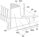
如图1、图2所示,一种秸秆板的铺平装置,包括:输送机10、支撑架20、龙门架30、电滚筒40、移动支架50、分料器60、挡板70,其中支撑架20为两个,分别固定在输送机10的两侧,分料器60通过支撑架20固定在输送机10的上方,输送机10的运行方向为从左向右运行,支撑架20的左侧连接有横梁21,横梁21上固定有电机22,电机22位于横梁21的左侧,横梁21开有贯穿其左右侧面的推送孔23;As shown in Figures 1 and 2, a straw board paving device includes: a
如图3、图4所示,所述分料器60包括:输料部61、出料部62、推送组件63,输料部61、出料部62均为中空结构,出料部62连接在输料部61的右侧,推送组件63从输料部61的左侧插入输料部61的内部,输料部61为“L”形,输料部61的竖直部分上端为进料口,输料部61的水平部分的顶板615向右下方倾斜,输料部61的内部设置有多个间隔相等的隔板611,隔板611位于输料部61的拐角处并将输料部61的内部分割成多个独立的输料通道612,隔板611位于输料部61竖直部分的顶面为刀刃状,隔板611的两板面均为粗糙的面,可使粉料从进料口进入后,落在隔板611刀刃状的顶端,在撞击力的作用下,部分成团的粉料将会散开,输料部61的左侧板开有多个与多个输料通道612位置一一对应的插孔613;As shown in FIG. 3 and FIG. 4 , the
上述出料部62由减缩通道621、平直通道622组成,减缩通道621的一端开口宽,另一端开口窄,出料部62通过减缩通道621宽的一端与输料部61连通,减缩通道621窄的一端与平直通道622连通,平直通道622的另一端为出料口,可使粉料从减缩通道621进入平直通道622后变得更加紧实;The above-mentioned
上述输料部61、出料部62的底面处于同一平面且均设置有多个间隔布置的半圆形凸条64;The bottom surfaces of the above-mentioned
如图1、图5、图6、图7所示,上述推送组件63包括:推板631、连接板632、推杆633、连接销634、连接杆635、偏心轴636、转盘二637、摩擦条638,推板631为多个并一一对应的位于多个输料通道612内,多个推板631的左端均穿过各自对应的插孔613延伸至输料部61的外部并连接在连接板632的右侧面上,推杆633的一端垂直连接在连接板632的左侧面上,另一端穿过横梁21的推送孔23并通过连接销634旋转的与连接杆635连接,连接杆635旋转的与偏心轴636连接,偏心轴636偏心的连接在转盘二637的下表面,转盘二637同轴的与电机22的电机轴连接,可使推板631在电机22的驱动下,沿输料通道612做往复运动;As shown in Figure 1, Figure 5, Figure 6, Figure 7, the
上述推板631位于输料通道612内时,推板631与隔板611的高度一致,推板631包括:研磨板6311、推送板6312,研磨板6311连接在推送板6312的上表面,研磨板6311从上至下逐渐变厚且其顶端刀刃状,研磨板6311的两板面均为粗糙的面,当推板631位于输料通道612内时,研磨板6311与其相邻的两个隔板611均不接触并各形成一上宽下窄的下落间隙6313,可使粉料从进料口进入后,部分成团的粉料将与研磨板6311刀刃状的顶端发生撞击,在撞击力的作用下,部分成团的粉料将会散开,而未发生撞击的成团的粉料将落入下落间隙6313,由于下落间隙6313是上宽下窄的,成团的粉料在其上部粉料和自身的重力作用下,将被抵压在研磨板6311与隔板611之间,在推板631往复运动以及隔板611、研磨板6311粗糙的板面作用下,成团的粉料将被揉搓散开;其中,由于粉料宽度大于下相邻推送板6312之间的间隙,使得被研磨板6311揉搓散开的粉料落在推送板6312顶端的斜坡面上;When the above-mentioned
上述插孔613与推板631左端的相匹配,可避免推板631往复运动时粉料从插孔613中漏出;The above-mentioned
上述推送板6312的左侧面高于其右侧面,推送板6312的右侧面垂直于其底面,推送板6312的顶面由水平的面63121和倾斜的面63122组成,水平的面63121位于倾斜的面63122的左侧,当推板631在输料通道612内做往复运动时,推送板6312的水平的面63121始终与插孔613的内壁面贴合,可避免推板631往复运动时粉料从插孔613中漏出,当推板631在输料通道612内做往复运动时,推送板6312的倾斜的面63122与输料部61的顶板615始终不接触,并在两者之间始终形成一倾斜的滑道63123,使被研磨板6311揉搓散开落在推送板6312顶端的斜坡面上的粉料沿着滑道63123下滑至推送板6312的右侧,并在推板631往复运动的作用下,粉料被推送至出料部62内部;The left side of the above-mentioned
上述输料部61的右侧内壁面上还设置有挡条614,挡条614的顶面为向左下方倾斜的面并高于隔板611,挡条614的下端延伸至输料通道612内,挡条614面向插孔613的面开有多个与多个研磨板6311位置一一对应且形状相匹配的滑槽6141,当推板631在输料通道612内做往复运动时,研磨板6311的右端始终位于滑槽6141内,可使下落的粉料沿挡条614的顶面滑落至研磨板6311、隔板611的顶部,避免推板631在输料通道612内做往复运动时,成团的粉料未经研磨散开就落入滑道63123内,在推板631做往复运动时,推板631始终与推板631不接触,可保证滑道63123始终畅通,挡条614的左下角为圆角结构,便于粉料进入滑道63123;A blocking
上述摩擦条638为多根,多根摩擦条638连接在连接板632的下端,并水平的位于输料部61、出料部62的底面多个凸条64的正下方,摩擦条638的上表面设置有多个间隔布置的弹性小半圆形凸点6381,可使摩擦条638在连接板632的带动下做往复运动时,摩擦条638与输料部61、出料部62的底板产生摩擦,从而使输料部61、出料部62产生振动,便于输料部61中的粉料下落以及出料部62中的粉料摊铺的更均匀;The above-mentioned friction strips 638 are multiple, and the multiple friction strips 638 are connected to the lower end of the connecting
如图1所示,所述龙门架30横跨并固定在输送机10的上方,沿输送机10运行的方向,龙门架30位于分料器60的下游,龙门架30的横梁上开有贯穿其上下表面的丝孔31,在丝孔31的两侧还分别开有一个贯穿龙门架30横梁的限位孔32;As shown in FIG. 1 , the
所述移动支架50的顶部中心处设置有螺杆51,移动支架50转动连接于螺杆51的底端,移动支架50通过螺杆51与龙门架30的丝孔31啮合安装在龙门架30上,螺杆51的顶端安装有转盘一53,通过转盘一53的转动,可带动移动支架50的上升和下降,移动支架50的顶部还设置有两个与龙门架30的限位孔32位置相对应且尺寸相匹配的导杆52,两个导杆52分别穿过龙门架30的两个限位孔32,通过导杆52对移动支架50进行导向,使其只能沿着导杆52上下移动,避免移动支架50发生转动;The top center of the
所述电滚筒40安装在移动支架50上,电滚筒40转动方向与输送机10的转动方向相反,进而在输送机10输送粉料时,利用电滚筒40的滚筒对粉料的上表面进行摊铺平整,电滚筒40的滚筒的表面上设有刷毛(图中未示出),通过刷毛可以对粉料的上表面进行扫动,可以去除多余的粉料,并将多余粉料填补在凹陷处,提高了摊铺效果;The
所述挡板70为两个,分别固定在龙门架30的支撑腿上,挡板70的底部与输送机10上输送带的上带面相贴,进而可以在电滚筒40碾压输送机10上的粉料时,对粉料的侧边进行阻挡,防止粉料散落。There are two
本发明的工作原理:The working principle of the present invention:
首先,使用时,根据生产需求,预先对电滚筒40的高度进行调整,调整方式为通过转盘一53旋转螺杆51,使得螺杆51带动移动支架50沿着导杆52上下移动,直至电滚筒40到达合适高度,之后启动输送机10、电滚筒40、电机22,推送组件63在电机22的驱动下,沿输料通道612做往复运动,接着将秸秆粉料输送至分料器60的输料部61的进料口,粉料从分料器60的输料部61的进料口进入,落在隔板611、研磨板6311刀刃状的顶端,在撞击力的作用下,部分成团的粉料将会散开,而未发生撞击的成团的粉料将落入下落间隙6313,由于下落间隙6313是上宽下窄的,成团的粉料在其上部粉料和自身的重力作用下,将被抵压在研磨板6311与隔板611之间,在推板631往复运动以及隔板611、研磨板6311粗糙的板面作用下,成团的粉料将被揉搓散开并从下落间隙6313落下的粉料沿着滑道63123下滑至推送板6312的右侧,并在推板631往复运动的作用下,粉料被推送至出料部62内部,同时在摩擦条638与输料部61、出料部62的底板摩擦的作用下,输料部61、出料部62产生振动,使输料部61中的粉料下落更加容易以及出料部62中的粉料摊铺的更均匀,接着粉料从出料部62的出料口下落至输送机10上,由于输送机10是从左向右运行的,粉料将向电滚筒40处移动,由于电滚筒40转动方向与输送机10的转动方向相反以及电滚筒40上的刷毛,可将粉料上表面多余的粉料清扫并填补在凹陷处,提高了摊铺效果,在电滚筒40对粉料摊铺的过程中,通过输送机10两侧的挡板70,可以有效避免粉料散落,节约原料,最终铺装在输送机10上的板坯的上、下表面更加平整且密度分布更均匀。First of all, when using, according to production requirements, adjust the height of the
Claims (1)
Priority Applications (1)
| Application Number | Priority Date | Filing Date | Title |
|---|---|---|---|
| CN202011586607.4A CN112692952B (en) | 2020-12-29 | 2020-12-29 | A device for laying straw boards |
Applications Claiming Priority (1)
| Application Number | Priority Date | Filing Date | Title |
|---|---|---|---|
| CN202011586607.4A CN112692952B (en) | 2020-12-29 | 2020-12-29 | A device for laying straw boards |
Publications (2)
| Publication Number | Publication Date |
|---|---|
| CN112692952A CN112692952A (en) | 2021-04-23 |
| CN112692952B true CN112692952B (en) | 2022-08-12 |
Family
ID=75511437
Family Applications (1)
| Application Number | Title | Priority Date | Filing Date |
|---|---|---|---|
| CN202011586607.4A Active CN112692952B (en) | 2020-12-29 | 2020-12-29 | A device for laying straw boards |
Country Status (1)
| Country | Link |
|---|---|
| CN (1) | CN112692952B (en) |
Families Citing this family (2)
| Publication number | Priority date | Publication date | Assignee | Title |
|---|---|---|---|---|
| CN116374428A (en) * | 2023-03-23 | 2023-07-04 | 桐乡市恒健塑业科技有限公司 | Anti-blocking feeding equipment for plastic part machining |
| CN117863297B (en) * | 2024-02-29 | 2025-11-18 | 南平市鸿联环保新材料有限公司 | A fire-resistant composite wood panel and its production equipment |
Family Cites Families (7)
| Publication number | Priority date | Publication date | Assignee | Title |
|---|---|---|---|---|
| GB395659A (en) * | 1933-03-20 | 1933-07-20 | Bernhard Pfeiffer | Improvements in devices for spreading textile and like fibres into a uniform fleece |
| EP1735131B1 (en) * | 2004-04-08 | 2007-12-05 | Ply-Pak (Proprietary) Limited | Fibre polymer composite (fpc) material |
| CN103287055B (en) * | 2012-02-23 | 2016-01-20 | 戴武兵 | Formaldehydeless fibrous material and forming method thereof and fiber decorative material and preparation method thereof |
| US20210107176A1 (en) * | 2016-11-29 | 2021-04-15 | Seiko Epson Corporation | Sheet manufacturing apparatus |
| CN207403134U (en) * | 2017-10-26 | 2018-05-25 | 安徽嘉农农林生态产业有限公司 | A kind of stalk produces plate powder lying device |
| CN207983625U (en) * | 2018-03-20 | 2018-10-19 | 沭阳县东泰木质纤维粉有限公司 | A kind of wood fibre board's plate embryo spreading machine |
| CN108189194A (en) * | 2018-03-20 | 2018-06-22 | 沭阳县东泰木质纤维粉有限公司 | A kind of wood fibre board's plate embryo spreading machine |
-
2020
- 2020-12-29 CN CN202011586607.4A patent/CN112692952B/en active Active
Also Published As
| Publication number | Publication date |
|---|---|
| CN112692952A (en) | 2021-04-23 |
Similar Documents
| Publication | Publication Date | Title |
|---|---|---|
| CN112692952B (en) | A device for laying straw boards | |
| CN112897119B (en) | Material flattening device for straw plate production | |
| CN112692951B (en) | A kind of straw board paving equipment | |
| CN110329616B (en) | Compaction split charging equipment for freeze-dried rice | |
| CN101549522B (en) | Vertical-blanking-mode material distributing machine of ceramic presser and distributing method thereof | |
| CN103818711A (en) | Mixed powder quantitative conveying and paving device | |
| CN203753896U (en) | Mixed powder quantitative conveying and flattening device | |
| CN115266710B (en) | Intelligent grading process and device for aggregate for concrete | |
| CN222803808U (en) | Tea matching processing mechanism | |
| CN201087557Y (en) | Concrete lying and plate girder type vibration device | |
| CN210477333U (en) | Automatic powder sprinkling machine | |
| CN116277448B (en) | A nano-stone slab production device and its production method | |
| CN109014042B (en) | Spreading device with cleaning mechanism | |
| CN219666998U (en) | Material distribution device for wet PC brick production | |
| CN219807484U (en) | Spreading fine material device of ecological plate spreading machine | |
| CN223369618U (en) | A circulating screen for a paving machine used in particleboard production | |
| CN219114357U (en) | Distributing device for producing ceramic rock plates | |
| CN211946953U (en) | Automatic retort device | |
| CN222972446U (en) | Swing cloth machine | |
| CN204624746U (en) | Quartz automatic distributing machine | |
| CN211366038U (en) | Feeding device on dry-mixed mortar production device | |
| CN220638318U (en) | Spreading device for producing solid wood particle shaving board | |
| CN222222925U (en) | Paving machine for manufacturing homogeneous high-strength chipboard | |
| CN119017730B (en) | Artificial stone spreading device | |
| CN217024075U (en) | Double-screw swing feeder of plant fiber board paving machine |
Legal Events
| Date | Code | Title | Description |
|---|---|---|---|
| PB01 | Publication | ||
| PB01 | Publication | ||
| SE01 | Entry into force of request for substantive examination | ||
| SE01 | Entry into force of request for substantive examination | ||
| GR01 | Patent grant | ||
| GR01 | Patent grant | ||
| TR01 | Transfer of patent right |
Effective date of registration: 20250212 Address after: Room 2202, 22 / F, Wantong building, No. 3002, Sungang East Road, Sungang street, Luohu District, Shenzhen City, Guangdong Province Patentee after: Shenzhen dragon totem technology achievement transformation Co.,Ltd. Country or region after: China Address before: 232068 5th floor, jianghuaiyun building, Shannan high tech Zone, Huainan City, Anhui Province Patentee before: Huainan Guandong Information Technology Co.,Ltd. Country or region before: China |
|
| TR01 | Transfer of patent right |