Detailed Description
Hereinafter, an air blowing device according to an embodiment of the present invention will be described.
[ embodiment ]
Fig. 1 is a perspective view showing a fan 1 according to one embodiment of the present invention. Fig. 2 is a block diagram showing the structure of the fan 1.
As shown in fig. 1 and 2, a fan (an example of an air blowing device) 1 is an air blowing device including 2 air blowers 11 and 12 (a first air blower 11 and a second air blower 12) each having an impeller 62. In the present embodiment, the fan 1 includes a first blower 11 on an inlet side (intake side) and a second blower 12 on an outlet side (exhaust side). In the present embodiment, the first blower 11 and the second blower 12 are mounted on an integrated frame, and the integrated fan 1 is configured.
The first blower 11 and the second blower 12 are axial flow fans arranged such that the rotation axis centers of the impellers 62 of the two blowers are aligned in the axial flow direction. The first blower 11 and the second blower 12 rotate the respective impellers 62 in different directions from each other. In other words, the rotation direction of the impeller 62 of the first blower 11 is a direction opposite to the rotation direction of the impeller 62 of the second blower 12 as viewed in the axial direction. That is, the fan 1 is a so-called double-reverse type blower. In the present embodiment, the fan 1 is a fan motor that discharges heat generated inside electronic equipment such as a computer and office equipment to the outside by wind power to cool the inside of the electronic equipment.
The fan 1 includes a communication line 45 connected to communicate between the first blower 11 and the second blower 12. Communication performed between the first blower 11 and the second blower 12 will be described later.
The first blower 11 includes a first motor 21 that rotates an impeller 62 of the first blower 11, and a first motor drive control device (an example of first drive control means, first communication means, and first abnormality detection means) 111. An impeller 62 is attached to a rotating shaft of a rotor of the first motor 21.
The second blower 12 includes a second motor 22 for rotating the impeller 62 of the second blower 12, and a second motor drive control device (an example of second drive control means, second communication means, and second abnormality detection means) 112. An impeller 62 is attached to a rotating shaft of a rotor of the second motor 22.
Hereinafter, the first motor 21 and the second motor 22 may be labeled as the motors 21 and 22 without distinguishing them from each other. Note that the first motor drive control device 111 and the second motor drive control device 112 may be denoted as motor drive control devices 111 and 112, respectively.
The motor drive controllers 111 and 112 drive the motors 21 and 22. In the present embodiment, the motors 21 and 22 are, for example, 3-phase brushless motors. The motor drive controllers 111 and 112 rotate the motors 21 and 22 by periodically passing a drive current through the coils of the motors 21 and 22.
The fan 1 is connected to a control device 800 as an example of an external device. In the present embodiment, the control device 800 outputs a speed command signal Sc (an example of speed command information) corresponding to the rotational speed (rotational speed) of the motors 21 and 22 to the blowers 11 and 12. The speed command signal Sc is input to the motor drive control devices 111 and 112. The motor drive control devices 111 and 112 can drive the motors 21 and 22 at the rotation speed corresponding to the speed command signal Sc. The motor drive controllers 111 and 112 output rotation speed signals S (for example, FG signals) corresponding to the motors 21 and 22 to the controller 800. The control device 800 can detect the driving state of each of the blowers 11, 12 based on the rotation speed signal S, and control the output speed command signal Sc based on the detection. Further, the rotation speed signal S may not be output to the outside of the fan 1.
In the present embodiment, the first motor drive control device 111 and the second motor drive control device 112 perform substantially the same operation except for the specific operation of the portions that communicate with each other as described later.
As will be described later, the first motor drive control device 111 functions as follows: as first drive control means for controlling the drive of the first motor 21, as first communication means for communicating with the second blower 12, and as first abnormality detection means for detecting the occurrence of an abnormality in the first blower 11. In addition, the second motor drive control device 112 functions as follows: a second drive control unit for controlling the drive of the second motor 22, a second communication unit for communicating with the first blower 11, and a second abnormality detection unit for detecting the occurrence of an abnormality in the second blower 12.
The first motor drive control device 111 and the second motor drive control device 112 have the same hardware configuration. Hereinafter, the same reference numerals are used for the components common to the first motor drive control device 111 and the second motor drive control device 112, and the description of the components is common to the first motor drive control device 111 and the second motor drive control device 112, except for the case where they are specifically described.
Each of the motor drive control devices 111 and 112 includes a motor drive unit 2 and a control circuit unit 3. The components of the motor drive control devices 111 and 112 shown in fig. 2 are a part of the whole, and the motor drive control devices 111 and 112 may have other components in addition to those shown in fig. 1.
In the present embodiment, each of the motor drive control devices 111 and 112 is an integrated circuit device (IC) in which a part (for example, the control circuit unit 3 and the motor drive unit 2) is packaged. Note that all of the motor drive control devices 111 and 112 may be packaged as 1 integrated circuit device, or all or a part of the motor drive control devices 111 and 112 may be packaged together with other devices to constitute 1 integrated circuit device.
The motor drive unit 2 includes an inverter circuit and a pre-drive circuit. The motor drive unit 2 outputs drive signals to the motors 21 and 22 based on the drive control signal Sd output from the control circuit unit 3, and drives the motors 21 and 22.
The pre-drive circuit generates an output signal for driving the inverter circuit based on the control of the control circuit unit 3 and outputs the output signal to the inverter circuit. The inverter circuit outputs a drive signal to the motors 21 and 22 based on an output signal output from the pre-drive circuit, and energizes the coils provided in the motors 21 and 22.
The speed command signal Sc output from the control device 800 is input to the control circuit unit 3. The control circuit unit 3 outputs a rotation speed signal S to the control device 800.
The speed command signal Sc is a signal related to the rotational speed of the motors 21 and 22. For example, the speed command signal Sc is a PWM (pulse width modulation) signal corresponding to the target rotational speed of the motors 21 and 22. In other words, the speed command signal Sc is speed command information corresponding to a target value of the rotational speed of the motors 21 and 22. Further, a clock signal may be input as the speed command signal Sc.
In the present embodiment, 3 hall signals (position detection signals) Hu, Hv, and Hw are input from the motors 21 and 22 to the control circuit unit 3. The HALL signals Hu, Hv, and Hw are output signals of, for example, 3 HALL (HALL) elements 25u, 25v, and 25w disposed in the motors 21 and 22. Hall signals Hu, Hv, and Hw are signals corresponding to the rotation of the rotors of motors 21 and 22. The control circuit unit 3 detects the rotation state of the motors 21 and 22 using the hall signals Hu, Hv, and Hw, and controls the driving of the motors 21 and 22. That is, the control circuit unit 3 detects the rotational position of the rotor of the motors 21 and 22 using the hall signals Hu, Hv, and Hw, and controls the driving of the motors 21 and 22. The control circuit unit 3 can obtain actual rotation speed information on the actual rotation speeds of the rotors of the motors 21 and 22 using the hall signals Hu, Hv, and Hw, and control driving of the motors 21 and 22.
The 3 hall elements 25 (1 hall element 25 is shown for the motors 21 and 22 in fig. 2 for simplicity) that output the hall signals Hu, Hv, and Hw are arranged around the rotors of the motors 21 and 22 at substantially equal intervals (120 degrees apart from the adjacent hall elements), for example. The 3 hall elements 25 detect magnetic poles of the rotors of the motors 21 and 22, respectively, and output hall signals Hu, Hv, and Hw.
Further, the present invention may be configured such that: in addition to or instead of the hall signals Hu, Hv, and Hw, the control circuit unit 3 inputs other information related to the rotation states of the motors 21 and 22. For example, a signal (pattern FG) generated using a coil pattern provided on a substrate on the rotor side may be input as an FG signal corresponding to the rotation of the rotor of the motors 21, 22. Further, the following configuration is possible: the rotation states of the motors 21 and 22 are detected based on the detection results of the rotation position detection circuit that detects the induced back electromotive forces of the respective phases (U, V, W phases) of the motors 21 and 22. It is also possible to provide encoders, rotary transformers, etc., and thereby detect information such as the rotational speeds of the motors 21, 22.
The control circuit unit 3 is constituted by, for example, a microcomputer, a digital circuit, and the like. The control circuit unit 3 outputs a drive control signal Sd for driving the motors 21 and 22 based on the input signal. Specifically, the control circuit unit 3 outputs the drive control signal Sd to the motor drive unit 2 based on the hall signals Hu, Hv, and Hw.
The control circuit unit 3 outputs a drive control signal Sd for driving the motors 21 and 22 to the motor drive unit 2, and controls the rotation of the motors 21 and 22. The motor drive unit 2 outputs a drive signal to the motors 21 and 22 based on the drive control signal Sd to drive the motors 21 and 22.
The control circuit unit 3 includes a rotation speed calculation unit 31, a speed command analysis unit 32, a PWM command unit 33, a PWM signal generation unit 35, a transmission/reception unit 37, a communication processing unit 38, and an abnormality determination unit 39.
The hall signals Hu, Hv, and Hw output from the 3 hall elements 25 are input to the rotation speed calculation unit 31. The rotation speed calculation unit 31 outputs position signals indicating the positional relationship between the phases and the rotors of the motors 21 and 22 based on the hall signals Hu, Hv, and Hw that are input. Further, the rotational speed calculation unit 31 generates and outputs actual rotational speed information corresponding to the period of the position signal based on the hall signals Hu, Hv, and Hw. That is, the rotational speed calculation unit 31 outputs actual rotational speed information related to the actual rotational speeds of the rotors of the motors 21 and 22. In the figure, the actual rotation signal S2 is shown in combination with the position signal and the actual rotational speed information. The actual rotation signal S2 is output to the PWM command unit 33.
The speed command analysis unit 32 receives a speed command signal Sc. The speed command analysis unit 32 outputs a target rotation speed signal S1 indicating the target rotation speed of the motors 21 and 22 based on the speed command signal Sc. The target rotation speed signal S1 is a PWM signal indicating a duty ratio corresponding to the speed command signal Sc. The target rotation speed signal S1 is output to the PWM command unit 33.
The PWM command unit 33 receives the actual rotation signal S2 output from the rotation speed calculation unit 31 and the target rotation speed signal S1 output from the speed command analysis unit 32. The PWM command unit 33 is also inputted with a setting signal S9 outputted from the communication processing unit 38 as described later. The PWM command section 33 generates and outputs a PWM setting instruction signal S3 indicating a duty ratio for outputting the drive control signal Sd. The PWM setting instruction signal S3 is output to the PWM signal generation unit 35.
The PWM signal generation unit 35 receives the PWM setting instruction signal S3. The PWM signal generation unit 35 generates a PWM signal S4 for driving the motor drive unit 2 based on the PWM setting instruction signal S3. The PWM signal S4 is, for example, a signal having the same duty ratio as that of the PWM setting instruction signal S3. In other words, the PWM signal S4 is a signal having a duty ratio corresponding to the PWM setting instruction signal S3.
The PWM signal S4 output from the PWM signal generation unit 35 is output from the control circuit unit 3 to the motor drive unit 2 as the drive control signal Sd. Thereby, the motor driving unit 2 outputs a driving signal to the motors 21 and 22 to drive the motors 21 and 22.
The transceiver 37 is an interface for performing communication. The transceiver 37 of the first blower 11 is connected to the transceiver 37 of the second blower 12 via a communication line 45. The number of the communication lines 45 may be 1 or plural, and the communication may be serial communication or parallel communication. The transceiver 37 of the first blower 11 can communicate with the transceiver 37 of the second blower 12. The communication processing unit 38 performs control related to communication.
The communication processing unit 38 controls the operation of the transceiver unit 37 and controls communication between the first blower 11 and the second blower 12. That is, the communication processing unit 38 of the first blower 11 controls the transmission/reception unit 37 of the first blower 11 to perform communication with the second blower 12. As will be described later, the communication processing unit 38 outputs the setting signal S9 to the PWM command unit 33 according to the content of communication between the first blower 11 and the second blower 12.
In the present embodiment, the first blower 11 and the second blower 12 are configured to be able to communicate with each other with the first blower 11 as a master and the second blower 12 as a slave. For example, the communication processing unit 38 of the first blower 11 makes an inquiry about the state of the second blower 12 to the second blower 12 via the transmission/reception unit 37. That is, the inquiry is made to transmit information indicating the driving state of the second motor 22 in the second blower 12 to the first motor drive control device 111. When receiving the inquiry from the first blower 11 via the transmission/reception unit 37, the communication processing unit 38 of the second blower 12 transmits a message regarding the state of the second blower 12, that is, the driving state of the second motor 22, to the first blower 11 via the transmission/reception unit 37 as a response to the inquiry. Further, the first blower 11 and the second blower 12 can communicate with each other, for example, as follows: a predetermined instruction command is transmitted from the first blower 11 to the second blower 12, and a response to the instruction command is transmitted from the second blower 12 to the first blower 11. As described above, the transmission/reception section 37 and the communication processing section 38 in the control circuit section 3 of the first motor drive control device 111 have a direct function as the first communication means, and the transmission/reception section 37 and the communication processing section 38 in the control circuit section 3 of the second motor drive control device 112 have a direct function as the second communication means.
The abnormality determination unit 39 detects whether or not the fans 11 and 12 are abnormal. That is, the abnormality determination unit 39 determines whether the blowers 11, 12 are in an abnormal state. When the abnormality determination unit 39 of the first blower 11 detects the occurrence of an abnormality in the first blower 11, the communication processing unit 38 of the first blower 11 operates in accordance with the abnormality. When the abnormality determination unit 39 of the second blower 12 detects the occurrence of an abnormality in the second blower 12, the communication processing unit 38 of the second blower 12 operates in accordance with the abnormality. As described above, the abnormality determination section 39 in the control circuit section 3 of the first motor drive control device 111 has a direct function as the first abnormality detection means, and the abnormality determination section 39 in the control circuit section 3 of the second motor drive control device 112 has a direct function as the second abnormality detection means.
For example, when the motors 21 and 22 cannot be normally driven due to disconnection of the motors 21 and 22, the abnormality determination unit 39 detects the occurrence of an abnormality. Further, for example, when the motors 21 and 22 are locked due to the foreign matter being caught in the impeller 62, the occurrence of an abnormality is detected. Note that the contents of the abnormality are not limited to these. That is, the object for directly detecting the state of occurrence of an abnormality (for example, abnormality of the rotational speed, temperature, current, or the like) is various, and in the present embodiment, the object to be detected is not particularly limited.
In the present embodiment, the control circuit unit 3 has a first drive mode and a second drive mode as drive modes for driving the motors 21 and 22. The first drive mode is a drive mode in which the motors 21 and 22 are driven at a rotation speed corresponding to the speed command signal Sc. The second drive mode is a drive mode in which the motors 21 and 22 are driven at a predetermined rotation speed higher than the rotation speed corresponding to the speed command information.
In the present embodiment, the second drive mode is a drive mode in which the motors 21 and 22 are driven at a predetermined rotation speed regardless of the input speed command signal Sc. More specifically, the second drive mode is a drive mode in which the motors 21 and 22 are driven to rotate with the maximum torque that can be output. In other words, the second drive mode is a drive mode in which the motors 21, 22 are driven as follows: the motors 21 and 22 of the blowers 11 and 12 are rotated at a maximum rotatable rotation speed (an example of a predetermined rotation speed).
When the control circuit unit 3 operates in the first drive mode, the PWM command unit 33 outputs the PWM setting instruction signal S3 based on the actual rotation signal S2, that is, the position signal and the actual rotation speed information, and the target rotation speed signal S1. Specifically, the PWM command unit 33 compares the target rotation speed signal S1 with actual rotation speed information corresponding to the rotation speeds of the motors 21 and 22, and generates the PWM setting instruction signal S3 so that the rotation speeds of the motors 21 and 22 correspond to the target rotation speed signal S1. Since the PWM setting instruction signal S3 is generated in this manner, the control circuit unit 3 outputs the drive control signal Sd based on the speed command signal Sc, and drives the motors 21 and 22 at the rotation speed corresponding to the speed command signal Sc.
On the other hand, when the control circuit unit 3 operates in the second drive mode, the PWM command unit 33 outputs the PWM setting instruction signal S3 generated in a predetermined form regardless of the target rotation speed signal S1. Specifically, the PWM command unit 33 generates the PWM setting instruction signal S3 so that the motors 21 and 22 rotate at the maximum rotatable speed in the blowers 11 and 12. For example, when the motors 21 and 22 can be driven when the maximum value of the duty ratio of the PWM signal S4 that can be output from the PWM signal generator 35 and the PWM setting instruction signal S3 that can be output from the PWM command unit 33 is 100% and the PWM signal S4 with the duty ratio of 100% is output, the PWM command unit 33 generates and outputs the PWM setting instruction signal S3 with the duty ratio of 100%. Since the PWM setting instruction signal S3 is generated from the motor drive control devices 111 and 112 in this manner, the control circuit unit 3 outputs the drive control signal Sd that is not based on the speed command signal Sc, and the motors 21 and 22 are driven at the maximum rotatable speed.
When both the first blower 11 and the second blower 12 are normally driven, the respective control circuit units 3 operate in the first drive mode. That is, the first blower 11 and the second blower 12 are driven at the rotation speeds based on the speed command signal Sc, respectively.
Here, in the present embodiment, the first blower 11 and the second blower 12 communicate via the communication line 45. Then, the first motor drive control device 111 controls the drive of the first motor 21 based on the result of the communication with the second blower 12. Specifically, the control circuit unit 3 of the first motor drive control device 111 switches between driving the first motor 21 in the first drive mode or driving the first motor 21 in the second drive mode different from the first drive mode, based on the result of communication with the second motor drive control device 112 of the second blower 12. Further, the second motor drive control device 112 controls the drive of the second motor 22 based on the result of the communication with the first blower 11. Specifically, the control circuit unit 3 of the second motor drive control device 112 switches between driving the second motor 22 in the first drive mode and driving the second motor 22 in the second drive mode based on the result of communication with the first motor drive control device 111 of the first blower 11.
The switching of the drive mode is performed, for example, as follows. In the present embodiment, the control circuit unit 3 is changed in which of the first drive mode and the second drive mode it operates, in accordance with the setting signal S9 output from the communication processing unit 38. That is, the communication processing unit 38 performs control for switching the driving mode of the control circuit unit 3.
The switching of the drive mode is performed in accordance with response content transmitted from the second blower 12 in response to an inquiry transmitted from the first blower 11 on the master side to the second blower 12 on the slave side.
Specifically, when the first blower 11 makes an inquiry about the second blower 12, the second motor drive control device 112 transmits a normal response or an abnormal response to the inquiry to the first motor drive control device 111.
That is, when the first blower 11 makes an inquiry about the second blower 12, if the driving state of the second motor 22 is normal, information indicating that is sent from the second motor drive control device 112 to the first motor drive control device 111 (normal response). In this way, when both the first blower 11 and the second blower 12 are normally driven, the respective control circuit units 3 operate in the first drive mode.
On the other hand, when the first blower 11 makes an inquiry about the second blower 12 and the driving state of the second motor 22 is not normal, information indicating that the driving state is abnormal is transmitted to the first motor drive control device 111. That is, in the second motor drive control device 112, when the abnormality of the second blower 12 is detected by the abnormality determination unit 39, the communication processing unit 38 transmits information indicating the abnormality to the first blower 11 via the transmission/reception unit 37 (abnormality response). In the first motor drive control device 111, the communication processing unit 38 switches the drive mode of the first motor 21 from the first drive mode to the second drive mode when receiving the information indicating that the abnormality has occurred in the second blower 12. That is, the communication processing unit 38 of the first blower 11 outputs the setting signal S9 to the PWM command unit 33 in response to the abnormality response transmitted from the second motor drive control device 112. In this way, the PWM command unit 33 switches from the state in which the PWM setting instruction signal S3 is output based on the target rotation speed signal S1 to the state in which the PWM setting instruction signal S3 is output such that the first motor 21 rotates at the predetermined rotation speed. Thereby, the first blower 11, in which no abnormality has occurred, is driven in the second drive mode.
The switching of the drive mode is also performed when the abnormality determination unit 39 detects the occurrence of an abnormality in the first blower 11.
That is, in the first motor drive control device 111, the communication processing unit 38 transmits an instruction to drive the second motor 22 in the second drive mode to the second blower 12 via the transmission/reception unit 37. In the second motor drive control device 112, when receiving an instruction to drive the second motor 22 in the second drive mode, the communication processing unit 38 switches the drive mode of the second motor 22 from the first drive mode to the second drive mode. That is, the communication processing unit 38 of the second blower 12 outputs the setting signal S9 to the PWM command unit 33 in accordance with the received instruction. In this way, the PWM command unit 33 switches from the state in which the PWM setting instruction signal S3 is output based on the target rotation speed signal S1 to the state in which the PWM setting instruction signal S3 is output such that the second motor 22 rotates at a predetermined rotation speed. Thereby, the second blower 12, in which no abnormality has occurred, is driven in the second drive mode.
The drive mode is switched in accordance with the presence or absence of an inquiry from the first blower 11 on the master side to the second blower 12 on the slave side and the presence or absence of a response to the inquiry.
Specifically, the inquiry from the first motor drive control device 111 to the second blower 12 is periodically made, and when the inquiry from the first motor drive control device 111 is not made for a predetermined time, the second motor drive control device 112 switches the drive mode of the second motor 22 from the first drive mode to the second drive mode. Thus, for example, when an abnormality occurs in the first blower 11 that the control circuit unit 3 cannot be operated any more because the power supply voltage cannot be supplied any more, the second blower 12, in which no abnormality has occurred, may be driven in the second drive mode.
Further, when a predetermined time has elapsed since the inquiry is made while the second blower 12 is not transmitting a response to the inquiry transmitted to the second blower 12, the first motor drive control device 111 switches the drive mode of the first motor 21 from the first drive mode to the second drive mode. Accordingly, for example, when an abnormality occurs in the second blower 12 such that the control circuit unit 3 cannot be operated any more due to the failure to supply the power supply voltage, the first blower 11, in which no abnormality has occurred, may be driven in the second drive mode.
When the first motor 21 is driven in the second drive mode, the first motor drive control device 111 switches the drive mode of the first motor 21 from the second drive mode to the first drive mode when information indicating that the second blower 12 is normal is obtained through communication with the second blower 12. When the second motor 22 is driven in the second drive mode, the second motor drive control device 112 switches the drive mode of the second motor 22 from the second drive mode to the first drive mode when information indicating that the first blower 11 is normal is obtained through communication with the first blower 11. Thus, when the abnormal state is eliminated, the drive control of the motors 21 and 22 based on the speed command signal Sc performed at the beginning is automatically performed.
Fig. 3 is a first flowchart showing an example of the processing operation performed by the control circuit unit 3 of the first motor drive control device 111. Fig. 4 is a second flowchart showing an example of the processing operation performed by the control circuit unit 3 of the first motor drive control device 111.
In the explanation of fig. 3 and 4, operations of the configuration of the first blower 11 are shown except for those described specifically.
As shown in fig. 3, in step S11, the communication processing unit 38 determines whether or not the abnormality determination unit 39 determines that the first air blower 11 is in an abnormal state in which an abnormality has occurred. If it is determined that the state is abnormal, the process proceeds to step S14 ("yes"), and if it is not determined that the state is abnormal, the process proceeds to step S12 ("no").
In step S12, the control circuit unit 3 controls the driving of the first motor 21 in accordance with the speed command signal Sc. That is, the PWM command unit 33 outputs the PWM setting command signal S3 based on the speed command signal Sc, and the control circuit unit 3 outputs the drive control signal Sd, whereby the motor drive unit 2 drives the first motor 21. That is, the first motor 21 is driven in the first drive mode.
In step S13, the communication processing unit 38 determines whether the confirmation time to make the inquiry has come. The confirmation time is, for example, a time when a predetermined time has elapsed since the last inquiry was made. If the confirmation time has come (yes), the process proceeds to step S17 in fig. 4. On the other hand, if the confirmation time has not come ("no"), the process returns to step S11.
In step S14, the communication processing unit 38 transmits the maximum rotation request command to the second blower 12 via the transmission/reception unit 37. The maximum rotation request command is an instruction for driving the second motor 22 in the second drive mode. By sending the maximum rotation request command, the drive mode of the second motor 22 is switched from the first drive mode to the second drive mode, and the second motor 22 is driven at the maximum rotational speed that can be rotated.
In step S15, the communication processing unit 38 determines whether or not the abnormality determination unit 39 determines that the first blower 11 is not in an abnormal state. If it is determined that the state is not in the abnormal state, the process proceeds to step S16 ("yes"), and if it is not determined that the state is not in the abnormal state (i.e., if it is determined that the state is in the abnormal state), step S15 ("no") is repeatedly executed.
In step S16, the communication processing unit 38 transmits a recovery command to the second blower 12 via the transceiver 37. The resume command is an instruction for driving the second motor 22 in the first drive mode. By sending the return command, the drive mode of the second motor 22 is switched from the second drive mode to the first drive mode, and the second motor is driven at the rotation speed corresponding to the speed command signal Sc. If the process of step S16 is executed, the process returns to step S11.
As shown in fig. 4, in step S17, the communication processing unit 38 makes an inquiry to the second blower 12. That is, the communication processing unit 38 transmits a confirmation command of the rotation state (hereinafter, may be simply referred to as a confirmation command) to the second blower 12 through the transmission/reception unit 37.
In step S18, the communication processing unit 38 determines whether or not the normal response transmitted from the second blower 12 is received. In the case where the normal response is received, the process returns to step S11 of fig. 3 ("yes"). If the normal response is not received, the process proceeds to step S19 ("no").
In step S19, the communication processing unit 38 determines whether or not the abnormality response transmitted from the second blower 12 is received. If an abnormal response is received, the process proceeds to step S21 ("yes"). If the abnormal response is not received, the process proceeds to step S20 ("no").
In step S20, the communication processing unit 38 determines whether or not a predetermined time has elapsed since the transmission of the confirmation command. If the predetermined time has elapsed since the confirmation command was transmitted, the process proceeds to step S21 ("yes"). If the predetermined time has not elapsed since the transmission of the confirmation command, the process returns to step S18 ("no").
In step S21, the control circuit unit 3 controls the first motor 21 so as to be driven at the maximum rotatable speed. That is, the communication processing unit 38 outputs the setting signal S9. The PWM command unit 33 outputs a PWM setting command signal S3 not based on the speed command signal Sc so that the first motor 21 rotates at the maximum rotation speed based on the setting signal S9. The drive control signal Sd is output from the control circuit section 3 in accordance with the PWM setting instruction signal S3 thus output, whereby the first motor 21 is driven in the second drive mode.
When the first motor 21 is driven in the second drive mode, the communication processing unit 38 determines whether or not the confirmation time to make the inquiry has come in step S22. If the confirmation time has not come (no), the process returns to step S21, and the driving in the second driving mode is continued. If the confirmation time comes (yes), the process returns to step S17.
That is, when the first motor 21 is driven in the second drive mode, the communication processing unit 38 periodically performs communication with the second blower 12 (step S17), and when a normal response is received from the second blower 12 (yes in step S18), the operation mode is returned from the second drive mode to the first drive mode (no in step S11, step S12). On the other hand, when the abnormality response is received from the second blower 12 (yes in step S19) or when a predetermined time has elapsed since the transmission of the confirmation command (yes in step S17), the driving in the second drive mode is continued.
Fig. 5 is a first flowchart showing an example of the processing operation performed by the control circuit unit 3 of the second motor drive control device 112. Fig. 6 is a second flowchart showing an example of the processing operation performed by the control circuit unit 3 of the second motor drive control device 112.
In the explanation of fig. 5 and 6, operations relating to the configuration of the second blower 12 are shown except for those described specifically.
As shown in fig. 5, in step S31, the control circuit unit 3 controls the driving of the second motor 22 in accordance with the speed command signal Sc. That is, the PWM command unit 33 outputs the PWM setting command signal S3 based on the speed command signal Sc and the control circuit unit 3 outputs the drive control signal Sd, so that the motor drive unit 2 drives the second motor 22. That is, the second motor 22 is driven in the first drive mode.
In step S32, the communication processing unit 38 determines whether or not the maximum rotation request command transmitted from the first blower 11 is received. In the case where the maximum rotation request command is received, the process proceeds to step S33 ("yes"). In a case where the maximum rotation request command is not received, it proceeds to step S35 ("no").
In step S33, the control circuit unit 3 controls the second motor 22 so as to be driven at the maximum rotatable speed. That is, the communication processing unit 38 outputs the setting signal S9. The PWM command unit 33 outputs a PWM setting command signal S3 that is not based on the speed command signal Sc so that the second motor 22 rotates at the maximum rotation speed based on the setting signal S9. The drive control signal Sd is output from the control circuit section 3 in accordance with the PWM setting instruction signal S3 thus output, whereby the second motor 22 is driven in the second drive mode. In other words, the drive mode of the second motor 22 is switched from the first drive mode to the second drive mode.
When the second motor 22 is driven in the second drive mode by receiving the maximum rotation request command in this manner, the communication processing unit 38 determines whether or not the return command transmitted from the first blower 11 is received in step S34. In the case where the recovery command is not received ("no"), it returns to step S33, and the driving in the second driving mode is continued. On the other hand, in the case where the recovery command is received ("yes"), the process returns to step S31, and the operation mode is returned from the second drive mode to the first drive mode (step S31).
In step S35, the communication processing unit 38 determines whether or not the confirmation command of the rotation state transmitted from the first blower 11 is received. In the case where the confirmation command is received, the process proceeds to step S39 of fig. 6 ("yes"). In a case where the confirmation command is not received, the process proceeds to step S36 ("no").
In step S36, the communication processing unit 38 determines whether or not a predetermined time has elapsed from the timing at which the confirmation command was received last time. If the predetermined time has elapsed since the timing of the previous reception, the process proceeds to step S37 ("yes"). If the predetermined time has not elapsed from the timing received last time, the process returns to step S32 ("no").
In step S37, the control circuit unit 3 controls the second motor 22 so as to be driven at the maximum rotatable speed. That is, the communication processing unit 38 outputs the setting signal S9. The PWM command unit 33 outputs a PWM setting command signal S3 that is not based on the speed command signal Sc so that the second motor 22 rotates at the maximum rotation speed based on the setting signal S9. The drive control signal Sd is output from the control circuit section 3 in accordance with the PWM setting instruction signal S3 thus output, whereby the second motor 22 is driven in the second drive mode.
When the second motor 22 is driven in the second drive mode by the elapse of the predetermined time from the timing at which the confirmation command was received last time, the communication processing unit 38 determines whether or not the confirmation command of the rotation state transmitted from the first air blower 11 is received in step S38. If the confirmation command is not received (no), the process returns to step S37 to continue the driving in the second driving mode. Upon receiving the confirmation command ("yes"), the process proceeds to step S39 of fig. 6.
That is, when the second motor 22 is driven in the second drive mode by the elapse of the predetermined time from the timing at which the confirmation command was received last time, the communication processing unit 38 continues the drive in the second drive mode until the confirmation command from the first blower 11 is received. When the confirmation command is received, the operation mode is returned from the second drive mode to the first drive mode in response to the confirmation command as follows (step S31).
As shown in fig. 6, in step S39, the communication processing unit 38 determines whether or not the abnormality determination unit 39 determines that the second blower 12 is in an abnormal state in which an abnormality has occurred. If it is determined that the state is abnormal, the process proceeds to step S40 ("yes"), and if it is not determined that the state is abnormal, the process proceeds to step S42 ("no").
In step S40, the communication processing unit 38 transmits information (abnormality response) indicating the abnormality of the second blower 12 to the first blower 11 via the transmission/reception unit 37. Thereby, the first motor 21 is driven in the second drive mode in the first blower 11.
After the abnormality response is performed, in step S41, the communication processing unit 38 determines whether or not the abnormality determination unit 39 determines that the second blower 12 is not in the abnormal state. If it is not determined that the state is not in the abnormal state, step S41 is repeatedly executed (no), and if it is determined that the state is not in the abnormal state, the process proceeds to step S42 (yes).
In step S42, the communication processing unit 38 transmits information (normal response) indicating that the second blower 12 is normal to the first blower 11 via the transmission/reception unit 37. In this case, the first blower 11 is changed from the first drive mode to the second drive mode, and the first motor 21 is driven at the rotation speed corresponding to the speed command signal Sc. That is, when the first motor 21 is driven in the first drive mode, the first motor 21 is kept continuously driven in the first drive mode. On the other hand, when the first motor 21 is driven in the second drive mode, the operation mode is switched from the second drive mode to the first drive mode, and the first motor 21 is driven.
In this manner, in the present embodiment, since the first blower 11 and the second blower 12 control the driving of the motors 21 and 22 based on the result of the mutual communication, the fan 1 as a whole operates as shown in fig. 7 to 11 below. Further, the detailed description of the operation performed by each of the blowers 11 and 12 is as described above, and therefore the description thereof is sometimes omitted hereinafter.
Fig. 7 is a timing chart illustrating an operation example of the fan 1 in a case where both the first blower 11 and the second blower 12 perform a normal operation.
As shown in fig. 7, when the first blower 11 on the master side is in a normal state, a command for confirming the rotation state is periodically transmitted to the second blower 12 on the slave side (step S101). That is, the first blower 11 checks the rotation state of the second motor 22 for the second blower 12.
In this way, the second blower 12 drives the second motor 22 in a normal state, and therefore, transmits information indicating normality to the first blower 11 (step S102). That is, the second blower 12 responds normally.
In this way, when the blowers 11 and 12 are in a normal state, the blowers 11 and 12 drive the motors 21 and 22 in the first drive mode.
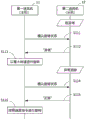
Fig. 8 is a timing chart illustrating a first operation example of the fan 1 in a case where the second blower 12 is in an abnormal state.
As shown in fig. 8, when the first blower 11 is in a normal state, a command for confirming the rotation state is periodically transmitted to the second blower 12 (step S111).
In this way, the second blower 12 is in an abnormal state, and therefore, transmits information indicating the abnormality to the first blower 11 (step S112). That is, the second blower 12 responds abnormally.
When the abnormality response is transmitted from the second blower 12 in this manner, the first blower 11 drives the first motor 21 at the maximum rotation speed (step S113). That is, in the first blower 11, the first motor 21 is driven in the second drive mode.
Thereafter, a case is assumed where the abnormality has been eliminated in the second blower 12. At this time, when the first blower 11 transmits a confirmation command of the rotation state to the second blower 12 (step S114), the second blower 12 transmits a normal response (step S115).
When the normal response is transmitted from the second blower 12 in this manner, the first blower 11 drives the first motor 21 so as to rotate at the rotation speed corresponding to the speed command signal Sc (step S116). That is, in the first blower 11, the operation mode is switched from the second drive mode to the first drive mode. Thereby, both the first blower 11 and the second blower 12 return to the state in which the motors 21, 22 are driven in the first drive mode.
Fig. 9 is a timing chart illustrating a second operation example of the fan 1 in a case where the second blower 12 is in an abnormal state.
As shown in fig. 9, when the first blower 11 is in a normal state, a command for confirming the rotation state is periodically transmitted to the second blower 12 (step S121).
Here, when the second blower 12 is in an abnormal state and a response to the confirmation command cannot be made within a predetermined time from the transmission of the confirmation command (step S122), the first blower 11 detects this.
In this way, the first blower 11 drives the first motor 21 at the maximum rotation speed (step S123). That is, in the first blower 11, the first motor 21 is driven in the second drive mode.
Thereafter, when the abnormality is eliminated in the second blower 12, a command for confirming the rotation state is transmitted from the first blower 11 to the second blower 12 (step S124), and a normal response is transmitted from the second blower 12 to the first blower 11 (step S125). Thereby, the first blower 11 performs control for driving the first motor 21 at the rotation speed corresponding to the speed command signal Sc (step S126). That is, both the first blower 11 and the second blower 12 return to the state in which the motors 21, 22 are driven in the first drive mode.
Fig. 10 is a timing chart illustrating a first operation example of the fan 1 in a case where the first blower 11 is in an abnormal state.
As shown in fig. 10, when the first blower 11 is in an abnormal state, the first blower 11 transmits a maximum rotation request command to the second blower 12 (step S151).
In this way, the second blower 12 drives the second motor 22 in a normal state, and therefore, the second blower transmits the normal information to the first blower 11 (step S152). That is, the second blower 12 responds normally. The second blower 12 may transmit a reply to the effect that the maximum rotation request command is received, or may not transmit a reply to the first blower 11, without performing a normal reply.
The second blower 12 that has received the maximum rotation request command drives the second motor 22 at the maximum rotation speed (step S153). That is, in the second blower 12, the operation mode is switched from the first drive mode to the second drive mode, and the second motor 22 is driven in the second drive mode.
Thereafter, a case is assumed in which the abnormality has been eliminated in the first blower 11. At this time, a return command for requesting a return to the first drive mode, which is the normal drive mode, is transmitted from the first blower 11 to the second blower 12 (step S154).
When the recovery command is thus transmitted from the first blower 11, the second blower 12 transmits a normal response (step S155). The second blower 12 drives the second motor 22 to rotate at a rotation speed corresponding to the speed command signal Sc (step S156). That is, in the second blower 12, the operation mode is switched from the second drive mode to the first drive mode. Thereby, both the first blower 11 and the second blower 12 return to the state in which the motors 21, 22 are driven in the first drive mode.
Fig. 11 is a timing chart illustrating a second operation example of the fan 1 in a case where the first blower 11 is in an abnormal state.
As shown in fig. 11, when the first blower 11 is in the normal state, a confirmation command of the rotation state is sent to the second blower 12 (step S161). On the other hand, when the second blower 12 is in the normal state, it transmits a normal response to the first blower 11 (step S162).
Here, if the first blower 11 becomes in an abnormal state, the transmission of the confirmation command from the first blower 11 to the second blower 12 is not possible. When the predetermined time has elapsed without sending the confirmation command since the confirmation command was sent last time (step S163), the second blower 12 detects this.
In this way, the second blower 12 drives the second motor 22 at the maximum rotation speed (step S164). That is, in the second blower 12, the second motor 22 is driven in the second drive mode.
Thereafter, when the abnormality is eliminated in the first blower 11, the transmission of the confirmation command for the rotation state of the second blower 12 from the first blower 11 is restarted (step S165). Further, at this time, first blower 11 may send a recovery command to second blower 12.
When the confirmation command is thus transmitted from the first blower 11, the second blower 12 transmits a normal response (step S166). The second blower 12 drives the second motor 22 to rotate at a rotation speed corresponding to the speed command signal Sc (step S167). That is, in the second blower 12, the operation mode is switched from the second drive mode to the first drive mode. Thereby, both the first blower 11 and the second blower 12 return to the state in which the motors 21, 22 are driven in the first drive mode.
Fig. 12 is a diagram showing an example of an air blowing system 801 configured by using a plurality of fans 1.
As shown in fig. 12, a plurality of fans 1 can be used in a collective manner. For example, the air blowing system 801 includes 1 control device 800 and 4 fans 1 ( fans 1A, 1B, 1C, and 1D). Each fan 1 is connected to the control device 800. When the operation mode is the first drive mode, the fans 11 and 12 of the fans 1 drive the motors 21 and 22 based on the speed command signal Sc input from the control device 800. In each fan 1, a first blower 11 and a second blower 12 are connected so as to be able to communicate with each other via a communication line 45.
The air blowing system 801 blows air from the fan 1 to the electronic device 900 such as a computer as a cooling target, for example. The electronic apparatus 900 is configured by a power supply device, a CPU, a memory, a storage device, a peripheral device, and the like. The electronic apparatus 900 can be cooled by the wind sent from the wind sending system 801 to the inside of the electronic apparatus 900, and can maintain a normal operation state.
Here, in the present embodiment, as described above, when one of the fans 11 and 12 in each fan 1 is abnormal and the impeller 62 cannot rotate, the operation mode of the other of the fans 11 and 12 is switched from the first operation mode to the second operation mode. In the second operation mode, the impeller 62 can be rotated at a higher rotation speed. Therefore, the air blowing capability that is reduced by the occurrence of an abnormality in one of the air blowers 11, 12 can be compensated for by the other air blower 11, 12. This makes it possible to send a large amount of air to the cooling target even before the fan 1 in which the abnormality has occurred is replaced with a normal fan.
In general, in the case where the fan 1 including the 2 fans 11 and 12 can sufficiently secure the air volume and the static pressure of the entire fan 1 according to the application, the controllable range of the rotation speed of each fan 11 and 12 (for example, the range of the rotation speed in which the feedback control of the rotation speed can be performed by outputting the speed command signal Sc to each fan 11 and 12 from the control device 800) is often set to a range more limited than the maximum rotation speed at which each fan 11 and 12 can rotate by itself.
In the case where the controllable range of the rotation speed of each of the blowers 11, 12 is more limited than the capability of the blowers 11, 12 themselves, for example, when the second blower 12 fails, even if the control is performed in which the speed command for the first blower 11 that has not failed is set to the maximum rotation speed in the controllable range, the first blower 11 is rotated only at the rotation speed that is more limited than the maximum rotation speed at which the first blower 11 itself can operate. If only such control is performed, sufficient air volume and static pressure cannot be ensured for the entire fan 1 when 1 fan 1 fails. For example, when the fan 1 is used for cooling a heat generating element, the heat generating element to be cooled may not be sufficiently cooled.
In contrast, in the present embodiment, for example, when the second blower 12 fails, the first blower 11 that has not failed drives the first motor 21 with the maximum rotatable torque. Therefore, even during the period until the fan 1 in which an abnormality occurs due to a failure or the like of the second blower 12 is replaced with a normal fan, as much air volume and as high static pressure as possible can be ensured. Therefore, even when one of the fans 11, 12 is in an abnormal state, the deterioration of the cooling performance can be suppressed only by the other fan 11, 12.
This will be described by way of example. It is assumed that, during normal driving in the first operation mode, when the duty ratio of the speed command signal Sc is 100%, the blowers 11 and 12 operate as follows. That is, the first blower 11 is driven and controlled so that the first motor 21 rotates at 20000 rpm. On the other hand, in the second blower 12, the duty ratio of the PWM setting instruction signal S3 is set to 50%, and the second motor 22 is drive-controlled so as to rotate at 10000 rpm.
In this case, if the first blower 11 is stopped due to a failure, the second blower 12 operates in the second drive mode. That is, the second blower 12 drives the second motor 22 at full torque. For example, the drive control is performed such that the duty ratio of the PWM setting instruction signal S3 is 100% of the maximum value, and the second motor 22 is rotated at 20000rpm, which is the maximum rotatable speed. Thus, even if the first blower 11 fails, the second blower 12 can be operated to compensate for the power drop, and the overall performance of the fan 1 can be prevented from being degraded.
Similarly, when the duty ratio of the speed command signal Sc is 100% during normal driving, the duty ratio of the PWM setting instruction signal S3 is set to 50% for each of the blowers 11 and 12, and the motors 21 and 22 are driven and controlled to rotate at 5000 rpm. In this case, when the first blower 11 is stopped due to a failure, the second blower 12 drives the second motor 22 at full torque with the duty ratio of the PWM setting instruction signal S3 set to 100% which is the maximum value. For example, the second motor 22 rotates at 10000rpm, which is the maximum rotational speed that can be rotated. When the second blower 12 is stopped due to a failure, the first blower 11 similarly drives the first motor 21 at full torque. Thus, even if the first blower 11 or the second blower 12 fails, the performance of the fan 1 as a whole can be suppressed from being degraded.
As described above, when one of the blowers 11, 12 is abnormal, the driving mode of the other of the blowers 11, 12 is switched according to the result of the communication between the blowers 11, 12. In other words, the blowers 11 and 12 monitor the operation states of each other, and when an abnormality occurs in one of the blowers, the drive mode is switched to the second drive mode in the other blower. Since the direct communication is performed between the blowers 11 and 12 and the drive mode is switched in this manner, for example, as compared with the case where the control device 800 grasps the states of the blowers 11 and 12 and switches the operating states, it is possible to more quickly perform the operation of increasing the rotation speed of one of the blowers 11 and 12 after the abnormality occurs in the other of the blowers 11 and 12. Since the fan 1 alone can perform the compensating operation when an abnormality occurs in one of the blowers 11 and 12, the control content of the control device 800 can be simplified, and the configuration of the air blowing system 801 can be simplified.
[ others ]
The fan constituting the fan and the motor drive control device thereof are not limited to the circuit configuration shown in the above embodiment. Various circuit configurations configured to be suitable for the purpose of the present invention can be applied. The features of the above embodiments may be partially combined to constitute the blower and the motor drive control device thereof. In the above embodiment, some components may not be provided or may be configured in other forms.
The control circuit unit is not limited to the control in the form of the operation predetermined for each drive mode. For example, when various kinds of control are performed by the control circuit unit, as a result, it is possible to evaluate that the mode of the operation is a mode suitable for the first operation mode or a mode suitable for the second operation mode. Even with such a configuration, it is possible to change the operation mode of the control circuit unit between a mode suitable for the first operation mode and a mode suitable for the second operation mode, which is referred to as switching of the operation mode of the control circuit unit.
The fan may not be connected to the control device. For example, when the operation mode is the first drive mode, each of the 2 motor drive control devices can drive each motor at a rotation speed corresponding to speed command information preset for the rotation speed of each motor.
The inquiry from the first motor drive control device to the second blower is not limited to be made periodically, and may be made aperiodically, for example. For example, the interval of the next inquiry may be changed so that the interval between the next inquiry and the subsequent inquiry is changed to a first interval (e.g., 100 msec) and a second interval (e.g., 200 msec) and a third interval (e.g., 300 msec) at a certain time. In this way, when the interval of the inquiry is irregular, it is sufficient to detect that an abnormality occurs when the interval of the inquiry exceeds a predetermined time (for example, 1 second) longer than the first interval, the second interval, and the third interval.
The communication method and the communication protocol of the first blower and the second blower are not limited to those of the above embodiments. Either one of the first blower and the second blower may be a host in communication. The first blower and the second blower may be configured to wirelessly communicate with each other. In this case, the communication line may not be provided.
The second drive mode is not limited to driving the motor at full torque. It is sufficient that the driving is performed at a higher rotation speed than the normal rotation speed (rotation speed in the case of driving in the first driving mode). That is, in the second drive mode, the duty ratio of the PWM setting instruction signal may be higher than that in the case of driving in the first drive mode.
The second blower may be disposed on the inlet side (intake side), and the first blower may be disposed on the outlet side (exhaust side). The rotation speed of the first motor and the rotation speed of the second motor in the case of driving in the first drive mode may be the same or different.
The fan may have a first blower and a second blower arranged in such a manner that the centers of the rotational shafts are not aligned. In addition, at least one of the first blower and the second blower may not be an axial flow fan.
The fan may have more than 3 blowers. In this case, at least 2 arbitrary blowers among the plurality of blowers may be configured to operate based on the result of performing communication as described above.
The driving of the first motor may be controlled only by the first blower based on a result of communication with the second blower, and the driving of the second motor may be controlled by the second blower without considering a result of communication with the first blower.
The motor driven by the motor drive control device according to the present embodiment is not limited to the 3-phase brushless motor, and may be a motor having another number of phases or another type of motor. The number of hall elements is not limited to 3. A position detection signal of the motor can be obtained using a detector different from the hall element. For example, a hall IC or the like may be used. The motor may be configured to be driven by a sensorless system without using a position detector such as a hall element or a hall IC.
The above-described flowcharts and the like are diagrams illustrating an example of the operation, and are not limited to this. The steps shown in the flowcharts are specific examples, and the present invention is not limited to this flowchart, and for example, the order of the steps may be changed, other processes may be inserted between the steps, or the processes may be performed in parallel.
Part or all of the processing in the above embodiments may be executed by software or may be executed by a hardware circuit. For example, the control circuit unit is not limited to a microcomputer. The internal configuration of the control circuit unit may be a configuration in which at least a part of the processing is performed by software.
The above embodiments are to be considered in all respects only as illustrative and not restrictive. The scope of the present invention is defined not by the above description but by the claims, and includes all modifications within the scope and meaning equivalent to the claims.
Description of the reference symbols
1 fan (an example of an air blowing device), 11 first air blower, 12 second air blower, 21 first motor, 22 second motor, 45 communication line, 62 impeller, 111 first motor drive control device (an example of a first drive control unit, a first communication unit, and a first abnormality detection unit), 112 second motor drive control device (an example of a second drive control unit, a second communication unit, and a second abnormality detection unit), 800 control device (an example of an external device), Sc speed command signal (an example of speed command information).