CN112585391B - Fluid handling coupling body with latch - Google Patents
Fluid handling coupling body with latch Download PDFInfo
- Publication number
- CN112585391B CN112585391B CN201980044072.7A CN201980044072A CN112585391B CN 112585391 B CN112585391 B CN 112585391B CN 201980044072 A CN201980044072 A CN 201980044072A CN 112585391 B CN112585391 B CN 112585391B
- Authority
- CN
- China
- Prior art keywords
- central longitudinal
- exterior
- latching mechanism
- longitudinal axis
- coupling
- Prior art date
- Legal status (The legal status is an assumption and is not a legal conclusion. Google has not performed a legal analysis and makes no representation as to the accuracy of the status listed.)
- Active
Links
Images


Classifications
-
- F—MECHANICAL ENGINEERING; LIGHTING; HEATING; WEAPONS; BLASTING
- F16—ENGINEERING ELEMENTS AND UNITS; GENERAL MEASURES FOR PRODUCING AND MAINTAINING EFFECTIVE FUNCTIONING OF MACHINES OR INSTALLATIONS; THERMAL INSULATION IN GENERAL
- F16K—VALVES; TAPS; COCKS; ACTUATING-FLOATS; DEVICES FOR VENTING OR AERATING
- F16K35/00—Means to prevent accidental or unauthorised actuation
- F16K35/02—Means to prevent accidental or unauthorised actuation to be locked or disconnected by means of a pushing or pulling action
- F16K35/022—Means to prevent accidental or unauthorised actuation to be locked or disconnected by means of a pushing or pulling action the locking mechanism being actuated by a separate actuating element
- F16K35/025—Means to prevent accidental or unauthorised actuation to be locked or disconnected by means of a pushing or pulling action the locking mechanism being actuated by a separate actuating element said actuating element being operated manually (e.g. a push-button located in the valve actuator)
-
- F—MECHANICAL ENGINEERING; LIGHTING; HEATING; WEAPONS; BLASTING
- F16—ENGINEERING ELEMENTS AND UNITS; GENERAL MEASURES FOR PRODUCING AND MAINTAINING EFFECTIVE FUNCTIONING OF MACHINES OR INSTALLATIONS; THERMAL INSULATION IN GENERAL
- F16L—PIPES; JOINTS OR FITTINGS FOR PIPES; SUPPORTS FOR PIPES, CABLES OR PROTECTIVE TUBING; MEANS FOR THERMAL INSULATION IN GENERAL
- F16L37/00—Couplings of the quick-acting type
- F16L37/08—Couplings of the quick-acting type in which the connection between abutting or axially overlapping ends is maintained by locking members
- F16L37/084—Couplings of the quick-acting type in which the connection between abutting or axially overlapping ends is maintained by locking members combined with automatic locking
- F16L37/0841—Couplings of the quick-acting type in which the connection between abutting or axially overlapping ends is maintained by locking members combined with automatic locking by means of a transversally slidable locking member surrounding the tube
-
- F—MECHANICAL ENGINEERING; LIGHTING; HEATING; WEAPONS; BLASTING
- F16—ENGINEERING ELEMENTS AND UNITS; GENERAL MEASURES FOR PRODUCING AND MAINTAINING EFFECTIVE FUNCTIONING OF MACHINES OR INSTALLATIONS; THERMAL INSULATION IN GENERAL
- F16D—COUPLINGS FOR TRANSMITTING ROTATION; CLUTCHES; BRAKES
- F16D39/00—Combinations of couplings according to two or more of the groups F16D31/00 - F16D37/00
-
- F—MECHANICAL ENGINEERING; LIGHTING; HEATING; WEAPONS; BLASTING
- F16—ENGINEERING ELEMENTS AND UNITS; GENERAL MEASURES FOR PRODUCING AND MAINTAINING EFFECTIVE FUNCTIONING OF MACHINES OR INSTALLATIONS; THERMAL INSULATION IN GENERAL
- F16L—PIPES; JOINTS OR FITTINGS FOR PIPES; SUPPORTS FOR PIPES, CABLES OR PROTECTIVE TUBING; MEANS FOR THERMAL INSULATION IN GENERAL
- F16L37/00—Couplings of the quick-acting type
- F16L37/28—Couplings of the quick-acting type with fluid cut-off means
- F16L37/30—Couplings of the quick-acting type with fluid cut-off means with fluid cut-off means in each of two pipe-end fittings
- F16L37/32—Couplings of the quick-acting type with fluid cut-off means with fluid cut-off means in each of two pipe-end fittings at least one of two lift valves being opened automatically when the coupling is applied
-
- F—MECHANICAL ENGINEERING; LIGHTING; HEATING; WEAPONS; BLASTING
- F16—ENGINEERING ELEMENTS AND UNITS; GENERAL MEASURES FOR PRODUCING AND MAINTAINING EFFECTIVE FUNCTIONING OF MACHINES OR INSTALLATIONS; THERMAL INSULATION IN GENERAL
- F16L—PIPES; JOINTS OR FITTINGS FOR PIPES; SUPPORTS FOR PIPES, CABLES OR PROTECTIVE TUBING; MEANS FOR THERMAL INSULATION IN GENERAL
- F16L37/00—Couplings of the quick-acting type
- F16L37/28—Couplings of the quick-acting type with fluid cut-off means
- F16L37/38—Couplings of the quick-acting type with fluid cut-off means with fluid cut-off means in only one of two pipe-end fittings
- F16L37/40—Couplings of the quick-acting type with fluid cut-off means with fluid cut-off means in only one of two pipe-end fittings with a lift valve being opened automatically when the coupling is applied
- F16L37/42—Couplings of the quick-acting type with fluid cut-off means with fluid cut-off means in only one of two pipe-end fittings with a lift valve being opened automatically when the coupling is applied the valve having an axial bore communicating with lateral apertures
Landscapes
- Engineering & Computer Science (AREA)
- General Engineering & Computer Science (AREA)
- Mechanical Engineering (AREA)
- Quick-Acting Or Multi-Walled Pipe Joints (AREA)
Abstract
一种流体处理联接件,可用于连接和断开流体处理系统的其他构件。例如,本文描述了一种便于联接/分离的流体联接件,并且当加压而经受旋转时,该流体联接件提供对意外断开的强抵抗力。在一些实施例中,凹联接件的闩锁机构有助于防止意外断开,该闩锁机构包括位于配合的凸联接件的沟槽中的突起。

A fluid handling coupling that can be used to connect and disconnect other components of a fluid handling system. For example, a fluid coupling is described herein that facilitates coupling/decoupling and that, when subjected to rotation under pressure, provides strong resistance to accidental disconnection. In some embodiments, a latch mechanism of the female coupler that helps prevent accidental disconnection includes a protrusion that sits in a groove of the mating male coupler.
Description
Cross-referencing of related applications
The present application claims priority from U.S. application No.62/712,092 filed on 30/7/2018. The disclosure of this prior application is considered part of the disclosure of the present application and the entire content thereof is incorporated into the present application.
Technical Field
This document relates to fluid handling couplings. For example, the present invention relates to a fluid coupling that facilitates coupling/decoupling and provides strong resistance to accidental decoupling when subjected to rotation when pressurized.
Background
Fluid handling components, such as fluid couplings, allow fluid communication between two or more components. Some fluid couplings include features that allow the male and female components to be quickly connected or disconnected, and may include one or more internal valve components that selectively block or allow fluid flow through the coupling.
Disclosure of Invention
This document describes a fluid handling coupling. For example, this document describes a fluid coupling that facilitates coupling/decoupling and provides strong resistance to unintentional disconnection when subjected to rotation when pressurized. In some embodiments, the latch mechanism of the female coupling, which includes a protrusion in a groove of the mating male coupling, helps prevent accidental disconnection.
In one aspect, the present disclosure is directed to a female fluid coupling including a coupling body defining a central longitudinal axis and an interior space for receiving a mating male coupling. The exterior of the interior space has an oblate cross-sectional shape. The interior of the interior space is cylindrical. A latch mechanism coupled to the body is laterally movable relative to the central longitudinal axis between a latched position and an unlatched position. A portion of the latch mechanism intersects the exterior of the interior space when the latch mechanism is in the latched position.
Such a female fluid coupling may optionally include one or more of the following features. The center of the oblate cross-sectional shape outside the interior space may be offset from the central longitudinal axis. The central longitudinal axis may coincide with a central axis of the cylindrical interior of the interior space. The oblate cross-sectional shape may be elliptical. The oval cross-sectional shape may be egg-shaped. The oblong cross-sectional shape may be oblong. The latch mechanism is movable between a latched position and an unlatched position along a transverse direction along which a major axis of the exterior oblate cross-sectional shape extends. The coupling body may also define a transition portion of the interior space between the exterior and the interior. The transition portion may include a surface extending at a non-zero angle relative to the central longitudinal axis. The non-zero angle may be 30 to 60 degrees. The portion of the latch mechanism that intersects the exterior of the interior space when the latch mechanism is in the latched position is on an opposite side of the exterior as compared to a location where a surface extending at a non-zero angle relative to the central longitudinal axis meets the exterior. The portion of the latch mechanism that intersects the exterior of the interior space when the latch mechanism is in the latched position can include a protrusion. In some embodiments, the protrusion does not extend into the interior space when the latch mechanism is in the unlocked position. The major axis of the outer oblate cross-sectional shape may intersect the protrusion. The protrusion may comprise a plastics material. The latch mechanism may be of a plastics material in its entirety. The fluid coupling may also include a valve disposed within the interior space. The valve is movable along the central longitudinal axis between an open configuration in which fluid may flow through the female fluid coupling and a closed configuration; in the closed configuration, fluid cannot flow through the female fluid coupling.
In another aspect, the present disclosure is directed to a fluid coupling system including a male coupling defining a central longitudinal axis, and a female coupling including an interior space defining a central longitudinal axis and for receiving an end of the male coupling. The exterior of the interior space has an oblate cross-sectional shape. The interior of the interior space is cylindrical. A latch mechanism coupled to the body is laterally movable relative to the central longitudinal axis between a latched position and an unlatched position. A portion of the latch mechanism intersects the exterior of the interior space when the latch mechanism is in the latched position. When the latch mechanism is in the latched position, the end of the male coupling may be inserted outside of the interior space.
Such fluid coupling systems may optionally include one or more of the following features. Further insertion of the end portion into the interior space may drive the portion of the latch mechanism out of the interior space and drive the latch mechanism toward the unlocked position. The central longitudinal axes of the coupler bodies of the male and female couplers may be spaced apart from each other when the latch mechanism is in the latched position with the end of the male coupler inserted outside of the interior space. When the male and female couplings are fully coupled together, the central longitudinal axes of the coupling bodies of the male and female couplings may coincide with each other.
Some embodiments of the devices, systems, and techniques described herein may provide one or more of the following advantages. First, the fluid couplings described herein facilitate coupling together. For example, the male coupling could simply be pushed into engagement with the female coupling, and the two would automatically lock together. Second, the fluid couplings described herein facilitate separation from one another. For example, the latching component of the female coupling may simply be depressed and then the male and female couplings may be separated from one another. Third, the fluid couplings described herein are designed to provide resistance to accidental disconnection when subjected to rotation under pressurization. Fourth, the fluid coupling described herein is economical to manufacture. For example, in some embodiments, the fluid couplings described herein are made almost entirely of injection molded thermoplastic components. Fifth, the female coupling described herein is compatible with the male coupling of the art. Thus, the improved female coupling described herein can be readily used to replace many existing female couplings.
The details of one or more implementations are set forth in the accompanying drawings and the description below. Other features and advantages will be apparent from the description and drawings, and from the claims.
Drawings
The present description is further provided with reference to the attached drawings, wherein like structure is referred to by like numerals throughout the several views, and wherein:
FIG. 1 is a perspective view of an exemplary male coupling and an exemplary female coupling in a disconnected state.
FIG. 2 is a perspective view of the male and female couplings of FIG. 1 in a coupled state.
Fig. 3 is an exploded perspective view of the female coupling of fig. 1.
Fig. 4 is an end (face) view of the female coupling of fig. 1.
Fig. 5 is a longitudinal cross-sectional view of the female coupling of fig. 1.
Fig. 6-11 are various views of a latch mechanism that may be used as part of the female coupling of fig. 1.
Fig. 12-17 are various views of a coupling body that may be used as part of the female coupling shown in fig. 1.
Fig. 18 and 19 illustrate how the latch mechanism of fig. 6-11 and the coupling body of fig. 12-17 are movably coupled to one another.
Fig. 20-25 are a series of longitudinal cross-sectional views of the male coupling of fig. 1 and the female coupling of fig. 1 during coupling together.
Fig. 26 and 27 show another latch mechanism.
Figures 28-33 show another female coupling.
Detailed Description
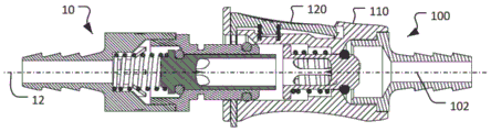
Referring to fig. 1, a fluid coupling system includes a male coupling 10 and a female coupling 100. As shown in fig. 2, the male coupling 10 and the female coupling 100 may be releasably coupled to one another to provide fluid communication between the male coupling end 14 and the female coupling end 104. In the coupled arrangement, the male coupling 10 and the female coupling 100 are mechanically locked or retained relative to each other. Thereafter, the male coupling 10 and the female coupling 100 can be disengaged from each other by depressing the latch mechanism 120. In some embodiments, when the male coupling 10 and the female coupling 100 are disengaged from each other, valves inside the male coupling 10 and the female coupling 100 are closed to prevent fluid from flowing out of the male coupling 10 and the female coupling 100.
Although ends 14 and 104 are depicted as barb fittings, any type of fluid connection may be used. For example, the ends 14 and/or 104 may be, but are not limited to, compression fittings, press-in fittings, luer fittings, threaded fittings (either internal or external), sanitary fittings, coiled tubing (pigtail), T-fittings, Y-fittings, and any other suitable type of configuration such that the male coupling 10 and the female coupling 100 are configured to connect to a fluid system as desired. In some embodiments, the male coupling 10 and/or the female coupling 100 can be provided with a removable cap (not shown) or another type of component that releasably connects with the ends 14 and/or 104.
One or more components of the male coupling 10 and/or the female coupling 100 are made of a material comprising a thermoplastic. In particular embodiments, the material from which the components of male coupling 10 and/or female coupling 100 are made is a thermoplastic, such as, but not limited to, acetal, polycarbonate, polysulfone, polyetheretherketone, polysulfide, polyester, polyvinylidene fluoride (PVDF), polyethylene, polyphenylsulfone (PPSU; for example ) Polyetherimide (PEI, for example @)>
 ) Polypropylene, polyphenylene, polyaryletherketone, and the like, and combinations thereof. In some embodiments, the material from which one or more components of the
 male coupling 10 and/or the female coupling 100 are made comprises a metal, such as, but not limited to, stainless steel, brass, aluminum, plated steel, and the like. In particular embodiments, the male coupling 10 and/or the female coupling 100 are metal-free. In some embodiments, the male coupling 10 and/or the female coupling 100 comprise one or more metal spring members (e.g., spring steel, stainless steel, etc.). In certain embodiments, the male coupling 10 and/or the female coupling 100 include one or more seals made of materials such as, but not limited to, silicone, fluoro-elastomer (FKM), ethylene Propylene Diene Monomer (EPDM), thermoplastic elastomer (TPE), nitrile rubber-N, thermoplastic vulcanizate (TPV), and the like.
The female coupling 100 includes a coupling body 110 defining a central longitudinal axis 102 and an interior space 112 for receiving the end 16 of the male coupling 10. The male coupling 10 defines a central longitudinal axis 12. As described further below, when the male coupling 10 and the female coupling 100 are fully coupled together (fig. 2), the central longitudinal axis 12 of the male coupling 10 and the central longitudinal axis 102 of the female coupling 100 are coincident and collinear with each other. However, during coupling of the male coupling 10 with the female coupling 100 (e.g., when the end 16 is inserted into the interior space 112), the central longitudinal axis 12 of the male coupling 10 and the central longitudinal axis 102 of the female coupling 100 are spaced apart from one another.
Referring to fig. 3, an exemplary embodiment of the female coupling 100 is shown in an exploded view. The female coupling 100 includes an end 104, a coupling body 110, a latching mechanism 120, a latch spring 130, a valve member 140, a valve spring 150, and a valve seal 160. The end 104 is connected to the coupling body 110 and extends along the central longitudinal axis 102.
The latch mechanism 120 is movably coupled to the coupling body 110. For example, as described further below, in the illustrated embodiment, the latch mechanism 120 is laterally movable relative to the central longitudinal axis 102 of the link body 110 between a latched position and an unlatched position. For example, when a user manually depresses the tab 122 of the latch mechanism 120, the latch mechanism 120 may move to the unlocked position.
A latch spring 130 is disposed between the latch mechanism 120 and the link body 110. Thus, the latch spring 130 biases the latch mechanism 120 toward the latched position. When a user of the female coupling 100 manually presses the latch mechanism 120 to the unlocked position, the latch spring 130 resists the manual force applied by the user. However, the user can easily overcome the resistance of the latch spring 130 in order to fully move the latch mechanism 120 to the unlatched position.
A valve spring 150 and a valve seal 160 are coupled to the valve member 140, and the valve assembly 140/150/160 is movably coupled to the coupling body 110. As described further below, the valve spring 150 biases the valve member 140 and the valve seal 160 to a closed position in which fluid flow through the coupling body 110 is blocked. When the male coupling 10 is fully coupled with the female coupling 100 (e.g., fig. 2), the end 16 of the male coupling 10 moves the valve member 140 relative to the coupling body 110 to an open position in which an open fluid flow path is established through the coupling body 110.
Referring to fig. 4 and 5, the female coupling 100 is shown in end view and longitudinal cross-sectional view, respectively. The latch mechanism 120 is shown in a latched position. The configuration of the interior space 112 is visible in these views. In particular, the interior space 112 includes an exterior 114, a transition portion 116, and an interior 118. A transition portion 116 is disposed between the outer portion 114 and the inner portion 118.
In the depicted embodiment, the outer portion 114 (which begins at the end face 111 of the female coupling 100) has an oblate circular cross-sectional shape (e.g., as shown in FIG. 4). In some embodiments, the oblong cross-sectional shape is oval, egg-shaped, oblong, or the like. The central axis 115 of the oblate cross-sectional shape of the outer portion 114 is offset from the central longitudinal axis 102 of the coupling body 110.
In the illustrated embodiment, the inner portion 118 is cylindrical. That is, the inner portion 118 has a circular cross-sectional shape. The central axis of the cylindrical interior 118 coincides with the central longitudinal axis 102 of the coupling body 110.
In the depicted embodiment, the transition portion 116 includes a contoured tapered surface 117 that extends at a non-zero angle relative to the central longitudinal axis 102 between the outer portion 114 and the inner portion 118. In some embodiments, the non-zero angle of the bevel 117 relative to the central longitudinal axis 102 is 40 to 50 degrees, 30 to 60 degrees, 20 to 70 degrees, 40 to 60 degrees, or 30 to 50 degrees, without limitation.
When the latch mechanism 120 is in the latched position (as shown), a portion of the latch mechanism 120 intersects the exterior 114 of the interior space 112. In the illustrated embodiment, the latch protrusion 124 of the latch mechanism 120 intersects the exterior 114 of the interior space 112 when the latch mechanism 120 is in the latched position. When the latch mechanism 120 is in the unlatched position, the latch protrusion 124 does not extend into the exterior 114 of the interior space 112. Latch protrusion 120 is located on an opposite side of outer portion 114 as compared to ramp 117 of transition portion 116. In some embodiments, the latch protrusion 124 is an arcuate member with an edge extending along a radial path from the center of the female coupling 100. In some embodiments, the arc length of the latch protrusion 124 is 55 and 65 degrees, 50 to 70 degrees, or 40 to 80 degrees.
It can be seen (see, e.g., fig. 4) that the latch protrusion 124 intersects the major axis of the oblate cross-sectional shape of the outer portion 114. In some embodiments, the latch protrusion 124 is centered on the long axis of the oblate cross-sectional shape of the outer portion 114. The latch mechanism 120 is movable between a latched position and an unlatched position in the same direction (transverse to the central longitudinal axis 102) as the direction in which the major axis of the oblate cross-sectional shape of the outer portion 114 extends.
Fig. 6-11 illustrate various views of an exemplary latch mechanism 120. The latch mechanism 120 includes a tab 122 and a latch protrusion 124. The latch mechanism 120 also defines a first side recess 126a and a second side recess 126b. As described further below, the first and second side recesses 126a-b cooperate with the coupling body 110 to movably couple the latch mechanism 120 to the coupling body 110.
Fig. 12-17 illustrate various views of an example coupling body 110. The link body 110 defines a slot 113, and the latch mechanism 120 movably resides in the slot 113 such that the latch mechanism 120 is movable between locked and unlocked configurations. The slot 113 extends perpendicular to the central longitudinal axis 102 of the coupling body 110. The coupling body 110 also defines a recess 119, and the tab 122 extends into the recess 119.
Fig. 18 and 19 further illustrate how the latch mechanism 120 is movably connected to the coupler body 110. Here, the cross-sectional view through the slot 113 reveals that the coupling body 110 includes a first protrusion 113a and a second protrusion 113b that are located in the first side recess 126a and the second side recess 126b, respectively, of the latch mechanism 120. Because the lateral dimensions of the protrusions 113a-b are less than the lateral lengths of the recesses 126a-b, the latch mechanism 120 is laterally movable relative to the coupler body 110. Specifically, the latch mechanism 120 is laterally movable relative to the coupling body 110 such that the latch protrusion 124 can be positioned: (i) The latching protrusion 124 extends into the exterior 114 of the interior space 112 and intersects the exterior 114 between a latched position and (ii) an unlatched position in which the latching protrusion 124 does not extend into the exterior 114 of the interior space 112.
Fig. 20 to 25 are a series of longitudinal sectional views of the male coupling 10 and the female coupling 100 in the process of coupling together. When the male and female couplings 10 and 100 are fully coupled and the latch mechanism 120 is in the latched position (as shown in fig. 25), the coupling systems 10 and 100 can be disengaged by manually depressing the latch mechanism 120 and then separating the male and female couplings 10 and 100 in the reverse order, as shown in fig. 20-25.
As shown in fig. 20-22, the end 16 of the male coupling 10 may be inserted into the exterior 114 (see fig. 4 and 5) when the latch mechanism 120 is in the latched position. In those described arrangements, the central longitudinal axis 12 of the male coupling 10 is spaced from the central longitudinal axis 102 of the female coupling 110. During initial insertion (e.g., with reference to fig. 21), the location of the latch protrusion 124 extending within the exterior 114 of the interior space 112 physically causes the central longitudinal axis 12 of the male coupling 10 to be spaced apart from the central longitudinal axis 102 of the female coupling 110.
As shown by a comparison of fig. 22 and 23, when the end 16 of the male coupling 10 enters the transition portion 116 (see fig. 4 and 5) and contacts the ramp 117, continued insertion movement will cause the male coupling 10 to move laterally relative to the female coupling 100 such that the central longitudinal axis 12 of the male coupling 10 will move into alignment with the central longitudinal axis 102 of the female coupling 110. Lateral movement of the male coupling 10 relative to the female coupling 100 is facilitated by the ramp 117 extending at a non-zero angle relative to the central longitudinal axis 102 of the female coupling 110. The end 16 of the male coupling 10 travels along the ramp 117 and in the process moves longitudinally and laterally relative to the female coupling 100. Further, because the side of end 16 opposite ramp 117 is adjacent to latch protrusion 124 of latch 120, continued insertion applies a lateral force to latch protrusion 124 from end 16, which causes latch 120 to move laterally toward the unlatched position. For example, when the latch mechanism 120 is in the latched position in fig. 22, the latch mechanism 120 is in the unlatched position in fig. 23. Lateral movement of the end 16 of the male coupling 10 drives the latch mechanism 120 to an unlocked position in which the latch protrusion 124 does not extend into the exterior 114 of the interior space 112.
Now, with the central longitudinal axis 12 of the male coupling 10 aligned with the central longitudinal axis 102 of the female coupling 110 (as shown in FIG. 23), continued insertion movement will cause the end 16 of the male coupling 10 to enter the interior 118 of the interior space 112 (as shown in FIG. 24). Further insertion will eventually result (as shown in fig. 25): (i) The latching protrusion 124 engages within the annular latching groove 17 defined by the end 16 of the male coupling 10, and (ii) the valves within the male coupling 10 and the female coupling 110 open such that an open fluid flow path is created between the ends 14 and 104. With the latch protrusion 124 engaged within the annular latch groove 17, the male coupling 10 and the female coupling 100 will releasably latch together until manual force depresses the tab 122 of the latch mechanism 120 a sufficient lateral distance to disengage the latch protrusion 124 from the annular latch groove 17.
Optional features and additional embodiments
Fig. 26 and 27 show an alternative design of the latch mechanism. In the depicted embodiment, the latch mechanism 220 includes a cantilevered leaf spring 230 that provides a bias toward the latched position as an alternative to the latch spring 130 (see fig. 3). The illustrated design using leaf springs 230 may provide an economical design because the latch mechanism 220 may be integrally molded, thereby eliminating the need for a separate spring and assembly process.
Fig. 28 to 33 show an alternative design of the female coupling. In the illustrated embodiment of the female coupling 300, the latch mechanism 320 forms at least a portion of the end face 317.
While this specification contains many specific implementation details, these should not be construed as limitations on the scope of any inventions or of what may be claimed, but rather as descriptions of features specific to particular embodiments of particular inventions. Certain features that are described in this specification in the context of separate embodiments can also be implemented in part or in whole in a single embodiment. Conversely, various features that are described in the context of a single embodiment can also be implemented in multiple embodiments separately or in any suitable subcombination. Furthermore, although features may be described herein as acting in certain combinations and/or initially claimed as such, one or more features from a claimed combination can in some cases be excised from the combination, and the claimed combination may be directed to a subcombination or variation of a subcombination.
Similarly, while operations are depicted in the drawings in a particular order, this should not be understood as requiring that such operations be performed in the particular order shown or in sequential order, or that all illustrated operations be performed, to achieve desirable results. Although many implementations have been described in detail above, other modifications are possible. For example, the logic flows depicted in the figures do not require the particular order shown, or sequential order, to achieve desirable results. In addition, other steps may be provided, or steps may be eliminated, from the described flows, and other components may be added to, or removed from, the described systems. Accordingly, other implementations are within the scope of the following claims.
Claims (16)
Applications Claiming Priority (3)
| Application Number | Priority Date | Filing Date | Title |
|---|---|---|---|
| US201862712092P | 2018-07-30 | 2018-07-30 | |
| US62/712,092 | 2018-07-30 | ||
| PCT/US2019/041770 WO2020028019A1 (en) | 2018-07-30 | 2019-07-15 | Fluid handling coupling body with latch |
Publications (2)
| Publication Number | Publication Date |
|---|---|
| CN112585391A CN112585391A (en) | 2021-03-30 |
| CN112585391B true CN112585391B (en) | 2023-04-11 |
Family
ID=69179507
Family Applications (1)
| Application Number | Title | Priority Date | Filing Date |
|---|---|---|---|
| CN201980044072.7A Active CN112585391B (en) | 2018-07-30 | 2019-07-15 | Fluid handling coupling body with latch |
Country Status (4)
| Country | Link |
|---|---|
| US (2) | US10975982B2 (en) |
| EP (1) | EP3830462B1 (en) |
| CN (1) | CN112585391B (en) |
| WO (1) | WO2020028019A1 (en) |
Families Citing this family (19)
| Publication number | Priority date | Publication date | Assignee | Title |
|---|---|---|---|---|
| DE102017118918A1 (en) * | 2017-08-18 | 2019-02-21 | Harting Electric Gmbh & Co. Kg | Push-button lock for a connector housing |
| WO2019034203A1 (en) | 2017-08-18 | 2019-02-21 | Harting Electric Gmbh & Co. Kg | LOCKING MECHANISM FOR CONNECTOR HOUSING |
| DE102017130005B3 (en) | 2017-12-14 | 2019-06-06 | Harting Electric Gmbh & Co. Kg | Connectors |
| CN111601997B (en) * | 2017-09-13 | 2022-08-09 | 可得制品公司 | Fluid processing component |
| WO2020251883A1 (en) * | 2019-06-10 | 2020-12-17 | Colder Products Company | Fluid handling couplings |
| USD947787S1 (en) * | 2020-04-30 | 2022-04-05 | Colder Products Company | Coupling |
| DE102020211212A1 (en) * | 2020-09-07 | 2022-03-10 | Fränkische Industrial Pipes GmbH & Co. KG | Receiving unit of a coupling device for fluid lines |
| US12203579B2 (en) | 2020-11-16 | 2025-01-21 | Colder Products Company | Fluid handling couplings |
| JP7618801B2 (en) * | 2020-11-16 | 2025-01-21 | コルダー プロダクツ カンパニー | Fluid Handling Fittings |
| TWI769669B (en) * | 2021-01-19 | 2022-07-01 | 佳必琪國際股份有限公司 | Electrical connector |
| CA3212416A1 (en) | 2021-03-19 | 2022-09-22 | Spencer Brislin BROWN | Quick connect shower head |
| US12460759B2 (en) * | 2021-10-06 | 2025-11-04 | Nordson Corporation | Aseptic coupling system with seal isolating connectors |
| EP4163530A1 (en) * | 2021-10-08 | 2023-04-12 | Hanil Tube Corporation | Coupling assembly with valves |
| US12044342B2 (en) | 2021-12-28 | 2024-07-23 | Cytiva Us Llc | Fluid connector with slidable member |
| US11796109B2 (en) | 2021-12-28 | 2023-10-24 | Cytiva Us Llc | Connector with rotatable tube |
| US12031654B2 (en) | 2021-12-28 | 2024-07-09 | Cytiva Us Llc | Fluid connector |
| CN114838217A (en) * | 2022-04-07 | 2022-08-02 | 倍仕得电气科技(杭州)股份有限公司 | Fluid connector and socket shell assembly |
| FR3155281B1 (en) * | 2023-11-15 | 2025-11-14 | Staubli Sa Ets | Female element of fluidic connection |
| USD1077148S1 (en) * | 2024-11-08 | 2025-05-27 | Wenzhou Furuisi Building Materials Co., Ltd. | Pipe fitting set |
Citations (9)
| Publication number | Priority date | Publication date | Assignee | Title |
|---|---|---|---|---|
| US5033777A (en) * | 1987-09-15 | 1991-07-23 | Colder Products Company | Male insert member having integrally molded part line free seal |
| US5074601A (en) * | 1989-10-07 | 1991-12-24 | Rasmussen Gmbh | Quick-release connector for flexible hoses and the like |
| US5806832A (en) * | 1995-10-20 | 1998-09-15 | Societe Y.T.O. | Quick coupler that uncouples in two stages |
| US6024124A (en) * | 1995-01-06 | 2000-02-15 | Colder Products Company | Low spill high flow quick coupling valve assembly |
| EP2245354A1 (en) * | 2008-01-28 | 2010-11-03 | Colder Products Company | Quick connect/disconnect coupling assemblies |
| CN103975186A (en) * | 2011-10-14 | 2014-08-06 | 可得制品公司 | connector |
| CN104455825A (en) * | 2013-09-13 | 2015-03-25 | 诺信公司 | Quick connect fluid conduit connector having latch with integral spring arms for button release |
| CN105637277A (en) * | 2013-10-03 | 2016-06-01 | 诺贝尔塑料公司 | Quick-connect clip-on connector |
| CN105782616A (en) * | 2015-01-14 | 2016-07-20 | 诺马美国控股有限责任公司 | Conduit Connector With A Primary And Secondary Latch |
Family Cites Families (19)
| Publication number | Priority date | Publication date | Assignee | Title |
|---|---|---|---|---|
| US738503A (en) | 1902-12-11 | 1903-09-08 | Frederick R Waters | Pipe-coupling. |
| US3718350A (en) | 1971-09-27 | 1973-02-27 | Gen Motors Corp | Snap ring coupling |
| US4105226A (en) | 1976-06-01 | 1978-08-08 | Celanese Corporation | Snap-in fittings and coupling ring therefor |
| US4603886A (en) | 1984-03-26 | 1986-08-05 | Vetco Offshore, Inc. | Snap type pipe connector |
| US4934655A (en) | 1989-03-13 | 1990-06-19 | Colder Products Company | Shutoff valve assembly |
| US5104158A (en) | 1989-03-13 | 1992-04-14 | Colder Products Company | Two piece molded female coupling |
| US5052725A (en) | 1989-03-13 | 1991-10-01 | Colder Products Company | Two piece molded female coupling |
| US5316041A (en) | 1992-10-27 | 1994-05-31 | Colder Product Company | Quick connection coupling valve assembly |
| JPH08114290A (en) | 1994-10-14 | 1996-05-07 | Exedy Corp | Fluid coupling |
| US5845943A (en) | 1996-12-02 | 1998-12-08 | Colder Products Company | Hybrid insert for fluid couplings |
| US6231089B1 (en) | 1999-03-10 | 2001-05-15 | Colder Products Company | Two piece molded female coupling |
| US7547047B2 (en) * | 2003-07-02 | 2009-06-16 | Colder Products Company | Coupler and method of making molded coupler |
| US20050057042A1 (en) | 2003-09-12 | 2005-03-17 | Wicks Jeffrey Clark | Push button bayonet tube connector |
| US7828336B2 (en) | 2004-12-09 | 2010-11-09 | Adroit Development, Inc. | Quick disconnect safety connector |
| US8087451B2 (en) | 2004-12-09 | 2012-01-03 | Adroit Development, Inc. | Pull release connectors |
| JP2006313010A (en) | 2005-04-04 | 2006-11-16 | Denso Corp | Piping joint device |
| FR2892491B1 (en) * | 2005-10-26 | 2009-01-16 | Legris Sa | CONNECTING DEVICE WITH SOLDER BODY |
| FR2927143B1 (en) | 2008-02-06 | 2010-03-19 | Staubli Sa Ets | FEMALE CONNECTING ELEMENT AND RAPID CONNECTING INCORPORATING SUCH A MEMBER |
| US8764068B2 (en) | 2012-05-10 | 2014-07-01 | Moen Incorporated | Quick connect coupling with retention feature |
-
2019
- 2019-07-15 WO PCT/US2019/041770 patent/WO2020028019A1/en not_active Ceased
- 2019-07-15 EP EP19844461.4A patent/EP3830462B1/en active Active
- 2019-07-15 US US16/511,156 patent/US10975982B2/en active Active
- 2019-07-15 CN CN201980044072.7A patent/CN112585391B/en active Active
-
2021
- 2021-04-05 US US17/222,240 patent/US11480264B2/en active Active
Patent Citations (9)
| Publication number | Priority date | Publication date | Assignee | Title |
|---|---|---|---|---|
| US5033777A (en) * | 1987-09-15 | 1991-07-23 | Colder Products Company | Male insert member having integrally molded part line free seal |
| US5074601A (en) * | 1989-10-07 | 1991-12-24 | Rasmussen Gmbh | Quick-release connector for flexible hoses and the like |
| US6024124A (en) * | 1995-01-06 | 2000-02-15 | Colder Products Company | Low spill high flow quick coupling valve assembly |
| US5806832A (en) * | 1995-10-20 | 1998-09-15 | Societe Y.T.O. | Quick coupler that uncouples in two stages |
| EP2245354A1 (en) * | 2008-01-28 | 2010-11-03 | Colder Products Company | Quick connect/disconnect coupling assemblies |
| CN103975186A (en) * | 2011-10-14 | 2014-08-06 | 可得制品公司 | connector |
| CN104455825A (en) * | 2013-09-13 | 2015-03-25 | 诺信公司 | Quick connect fluid conduit connector having latch with integral spring arms for button release |
| CN105637277A (en) * | 2013-10-03 | 2016-06-01 | 诺贝尔塑料公司 | Quick-connect clip-on connector |
| CN105782616A (en) * | 2015-01-14 | 2016-07-20 | 诺马美国控股有限责任公司 | Conduit Connector With A Primary And Secondary Latch |
Also Published As
| Publication number | Publication date |
|---|---|
| EP3830462A1 (en) | 2021-06-09 |
| CN112585391A (en) | 2021-03-30 |
| US10975982B2 (en) | 2021-04-13 |
| EP3830462A4 (en) | 2021-09-01 |
| US20200032922A1 (en) | 2020-01-30 |
| US11480264B2 (en) | 2022-10-25 |
| EP3830462B1 (en) | 2023-10-18 |
| WO2020028019A1 (en) | 2020-02-06 |
| US20210222793A1 (en) | 2021-07-22 |
Similar Documents
| Publication | Publication Date | Title |
|---|---|---|
| CN112585391B (en) | Fluid handling coupling body with latch | |
| US12366316B2 (en) | Fluid couplings | |
| US20230243447A1 (en) | Aseptic fluid couplings | |
| CN114127456B (en) | Fluid treatment coupling | |
| CN103269744A (en) | Shut-off valves for fluid line connectors | |
| JP7618801B2 (en) | Fluid Handling Fittings | |
| US20240353041A1 (en) | Fluid handling couplings | |
| US20250109813A1 (en) | Fluid handling couplings | |
| US20260085778A1 (en) | Fluid handling couplings | |
| WO2025096434A1 (en) | Fluid couplings with canted coil spring latching mechanisms |
Legal Events
| Date | Code | Title | Description |
|---|---|---|---|
| PB01 | Publication | ||
| PB01 | Publication | ||
| SE01 | Entry into force of request for substantive examination | ||
| SE01 | Entry into force of request for substantive examination | ||
| GR01 | Patent grant | ||
| GR01 | Patent grant |