Disclosure of Invention
The application provides a water storage device, tree planting device and tree planting method can carry out the utilization of maximum efficiency to precipitation, solves the technical problem that moisture is difficult to the maximize and utilizes under the adverse circumstances.
In view of the above, a first aspect of the present application provides a water storage apparatus, the apparatus comprising:
a U-shaped box body and a connecting piece;
the U-shaped box body comprises two side flow pipelines which are oppositely arranged and a bottom flow pipeline which is positioned between the two side flow pipelines; both of the side flow channels are communicated with the bottom flow channel;
the side walls of the two side flow pipelines and the bottom flow pipeline are recessed inwards, so that a cylindrical tree planting cavity with a long notch is formed in the center of the U-shaped box body; the long notch is communicated with the opening of the U-shaped box body, a trunk channel is formed between the long notch and the opening, and a trunk can be arranged in the quasi-cylindrical tree planting cavity through the trunk channel;
the connecting piece comprises a connecting plate and a reinforcing plate, the connecting plate is provided with an arc-shaped filling block and a channel filling block, the arc-shaped filling block is arranged at one end of the channel filling block, and the reinforcing plate is fixedly arranged at the other end of the channel filling block; the connecting plate fixed mounting be in the top of U type box, make arc filling up the piece and fix the breach department of long breach, the passageway filling up the piece and fixing the top of trunk passageway.
Preferably, the side flow channel and the underflow channel are linear or arcuate in shape.
Preferably, the notch of the long notch is provided with a limiting groove, the arc-shaped filling-in block is provided with a limiting bulge, and the limiting groove and the limiting bulge are fixed at the notch of the long notch.
Preferably, the lateral wall of the trunk channel is provided with a limiting groove, the channel vacancy filling block is provided with a limiting protrusion, and the channel vacancy filling block is fixed to the top end of the trunk channel through the limiting groove and the limiting protrusion.
Preferably, the other end of the channel vacancy filling block is provided with a mounting hole, the bottom wall of the reinforcing plate is provided with a screw, and the reinforcing plate is fixedly mounted in the mounting hole of the channel vacancy filling block through the screw.
Preferably, the channel vacancy filling block is of a structure with a high middle part and two low sides.
Preferably, the outer edge of the other end of the channel vacancy filling block is provided with a surrounding bulge.
Preferably, the bottom wall of the U-shaped box body is provided with an irrigation hole.
Preferably, the water storage device further comprises a water outlet strip, one end opening of the water outlet strip penetrates through the irrigation hole and is arranged inside the U-shaped box body, and the other end opening of the water outlet strip is attached to the outside of the U-shaped box body.
Preferably, the water storage device further comprises a support net, the shape of the support net is matched with that of the U-shaped box body, and the support net is fixed on the surface of the U-shaped box body.
Preferably, the support net is provided with micropores through which water may not pass through sand.
Preferably, the supporting net is provided with a grid structure and a separation material layer, the separation material layer is fixed on the surface of the grid structure, and the separation material layer is a material layer which can not pass water through sand.
A second aspect of the application provides a tree planting device comprising the water storage device, a water collecting tray and an anti-evaporation piece;
the evaporation-proof part is fixed at the mouth of the cylindrical tree planting cavity of the water storage device;
the water collecting tray is fixed on the evaporation preventing part, so that the water collecting tray covers the surface of the water storage device through the evaporation preventing part.
Preferably, the tree planting device further comprises a protective cover, the protective cover comprises a cylindrical body matched with the similar cylindrical tree planting cavity, the protective cover is arranged inside the similar cylindrical tree planting cavity, and the protective cover protrudes out of the cavity opening of the similar cylindrical tree planting cavity.
Preferably, the protective cover is provided with air holes.
In a third aspect, the present application provides a method for planting trees, which uses the tree planting device, the method comprising:
digging a device pit for placing the tree planting device, wherein the depth of the device pit is smaller than the height of the water storage device;
digging a tree planting pit for planting trees in the middle of the device pit;
placing the roots of the plants to be planted into the planting pits and filling the planting pits with soil;
the stems of the plants to be planted are arranged in the quasi-cylindrical tree planting cavity through the trunk channel, the arc-shaped filling blocks are fixed at the gaps of the long gaps, the channel filling blocks are fixed at the top end of the trunk channel, the holes of the device pits are filled with soil, and the water storage device is fixed;
enclosing the evaporation-proof part on the stem of the plant to be planted and fixedly arranging the evaporation-proof part on the cavity opening of the cylindrical tree planting cavity;
fixing the water collecting tray on the evaporation preventing part, covering the water storing device with the water collecting tray, and fixing the edge of the water collecting tray with soil.
This application discovery current water storage box all is split type integrated configuration, and water storage box quantity is two, and the lateral wall of two water storage boxes is installed relatively, and is also that two water storage boxes are each other rotational symmetry, and the depressed part of two forms a region that link up from top to bottom jointly, wraps up the trunk in this region, then can fix two water storage boxes in the both sides of trunk, passes through draw-in groove and buckle at last, perhaps the buckle with two water storage box fixed connection. This application discovers current split type water storage box is installing the in-process at the trunk, there is the installation loaded down with trivial details, the defect that the installation condition is harsh, firstly, before installing the water storage box, need be with regional flattening around the trunk, make the regional same horizontal plane that is in around the trunk, then, fix two water storage boxes in the both sides of trunk, make the connecting piece of two water storage boxes be in on the same level, it is fixed with two water storage boxes to use connecting piece (buckle or buckle etc.) at last, whole installation is on average 15-30 minutes consuming time, and to on the region of ground unevenness or hillside, be difficult to with regional flattening around the trunk, these regions are unable installation water storage box, just also can't plant the tree, its range of application is very narrow. Therefore, the existing water storage box can be installed in three steps in the installation process, the consumed time is long, the requirement on the flatness of the ground is very high, and the water storage box is difficult to use in the area with the slope.
The water storage device is designed based on the defects of the existing water storage box, the water storage device is of an integrated structure, a device pit for placing a tree planting device is dug during installation, and the depth of the device pit is smaller than the height of the water storage device; digging a tree planting pit for planting trees in the middle of the device pit; putting the roots of the plants to be planted into the planting tree pits, and filling the planting tree pits with soil; the stems of plants to be planted are arranged in the quasi-cylindrical tree planting cavity through the trunk channel, the arc-shaped gap filling blocks are fixed at the gap of the long gap, the channel gap filling blocks are fixed at the top end of the trunk channel, and the water storage device is fixed by filling the holes of the device pit with soil; enclosing the evaporation-proof part on the stem of the plant to be planted and fixedly arranging the evaporation-proof part on the cavity opening of the quasi-cylindrical tree planting cavity; the water collecting tray is fixed on the evaporation preventing part, so that the water collecting tray covers the water storage device, and the edge of the water collecting tray is fixed by soil. According to statistics, the water storage device takes 5-10 minutes averagely when being installed, and can be applied to an area with uneven ground or a hillside.
The water storage device is of an integrated structure, installation is very simple, only a device pit for placing the water storage device is dug, and the U-shaped box body is of an integrated structure and does not require the periphery of a plant to be planted to be very flat, so that the defect that two water storage boxes need to be placed on the same horizontal plane respectively and then connected in the prior art and installation is complex is overcome; in addition, the U-shaped box body is of an integral structure, so that the U-shaped box body can be easily installed on a slope body; the utility model provides a water storage device's trunk passageway is used for treating the passing through of planting the plant, then the arc mends the breach of lacking the piece with long breach, forms the accent in complete class cylindric tree planting chamber, and the passageway mends the piece and fills the trunk passageway for two side flows lead to the pipe connection, thereby improve the intensity of U type box, wherein, the reinforcing plate has effectively improved the intensity of connecting plate, still plays the effect of intercepting the rainwater.
Detailed Description
The technical solutions of the embodiments of the present application will be described clearly and completely with reference to the accompanying drawings, and it is obvious that the described embodiments are some, but not all, of the embodiments of the present application. All other embodiments obtained by a person of ordinary skill in the art based on the embodiments in the present application without any creative effort belong to the protection scope of the embodiments in the present application.
In the description of the embodiments of the present application, it should be noted that the terms "center", "upper", "lower", "left", "right", "vertical", "horizontal", "inner", "outer", and the like indicate orientations or positional relationships based on the orientations or positional relationships shown in the drawings, and are only for convenience in describing the embodiments of the present application and simplifying the description, but do not indicate or imply that the referred devices or elements must have specific orientations, be configured in specific orientations, and operate, and thus, should not be construed as limiting the embodiments of the present application. Furthermore, the terms "first," "second," and "third" are used for descriptive purposes only and are not to be construed as indicating or implying relative importance.
In the description of the embodiments of the present application, it should be noted that the terms "mounted," "connected," and "connected" are to be construed broadly and may be, for example, fixedly connected, detachably connected, or integrally connected unless explicitly stated or limited otherwise; can be mechanically or electrically connected; they may be connected directly or indirectly through intervening media, or they may be interconnected between two elements. Specific meanings of the above terms in the embodiments of the present application can be understood in specific cases by those of ordinary skill in the art.
It should be understood that the present application is applicable to the planting of trees in arid or semi-arid regions, as shown in FIGS. 1 to 11, fig. 1 is a structural view of a water storage apparatus according to an embodiment of the present application, fig. 2 is a structural view of a U-shaped tank of fig. 1 from a first perspective, FIG. 3 is a second perspective view structural view of the U-shaped case of FIG. 1, FIG. 4 is a first perspective view structural view of the connection plate of FIG. 1, fig. 5 is a second perspective view structural view of the connection plate of fig. 1, fig. 6 is a third perspective view structural view of the connection plate of fig. 1, fig. 7 is a fourth view structural view of the connection plate of fig. 1, fig. 8 is a fifth view structural view of the connection plate of fig. 1, fig. 9 is a first perspective view structural view of the reinforcing plate of fig. 1, fig. 10 is a second perspective view structural view of the reinforcing plate of fig. 1, FIG. 11 is a third perspective view of the U-shaped box of FIG. 1, as shown in FIGS. 1 to 11, FIG. 1 includes a U-shaped box 1 and a connecting member 2;
the U-shaped box body comprises two side flow pipelines 1-1 which are oppositely arranged and a bottom flow pipeline 1-2 which is positioned between the two side flow pipelines; the two side flow pipelines 1-1 are both communicated with the bottom flow pipeline 1-2;
the side walls of the two side flow pipelines 1-1 and the bottom flow pipeline 1-2 are concave, so that a cylindrical tree planting cavity 1-4 with a long gap 1-3 is formed in the center of the U-shaped box body 1; the long notch 1-3 is communicated with the opening 1-5 of the U-shaped box body, a trunk channel 1-6 is formed between the long notch 1-3 and the opening 1-5, and a trunk can be arranged in the cylinder-like tree planting cavity 1-4 through the trunk channel 1-6;
the connecting piece 2 comprises a connecting plate and a reinforcing plate 2-1, the connecting plate is provided with an arc-shaped supplement block 2-2 and a channel supplement block 2-3, the arc-shaped supplement block 2-2 is arranged at one end of the channel supplement block 2-3, and the reinforcing plate is fixedly arranged at the other end of the channel supplement block 2-3; the connecting plate 2 is fixedly arranged at the top end of the U-shaped box body 1, so that the arc-shaped filling block 2-2 is fixed at the gap of the long gap 1-3, and the channel filling block 2-3 is fixed at the top end of the trunk channel 1-6.
The connecting plate 2 is fixedly installed at the top end of the U-shaped box body 1, so that the arc-shaped filling block 2-2 is fixed at the gap of the long gap 1-3, the arc-shaped filling block 2-2 fills the gap of the long gap 1-3 to form a complete cavity opening 1-7 of the cylindrical tree planting cavity, and the channel filling block 2-3 is fixed at the top end of the trunk channel 1-6, so that the two side flow pipelines 1-1 are connected.
The water storage device designed by the application is of an integrated structure, and during installation, a device pit for placing the tree planting device is dug, wherein the depth of the device pit is smaller than the height of the water storage device; digging a tree planting pit for planting trees in the middle of the device pit; putting the roots of the plants to be planted into the planting tree pits, and filling the planting tree pits with soil; the stems of plants to be planted are arranged in the quasi-cylindrical tree planting cavities 1-4 through trunk channels 1-6, the arc-shaped filling blocks 2-2 are fixed at the gaps of the long gaps 1-3, the channel filling blocks 2-3 are fixed at the top ends of the trunk channels 1-6, and the water storage device is fixed by filling the holes of the device pits with soil; enclosing the evaporation-proof part on the stem of the plant to be planted, and fixedly arranging the evaporation-proof part on the cavity opening 1-7 of the quasi-cylindrical tree planting cavity; the water collecting tray is fixed on the evaporation preventing part, so that the water collecting tray covers the water storage device, and the edge of the water collecting tray is fixed by soil. According to statistics, the water storage device takes 5-10 minutes averagely when being installed, and can be applied to an area with uneven ground or a hillside.
The water storage device is of an integrated structure, installation is very simple, and only a device pit for placing the water storage device is dug, and the U-shaped box body 1 is of an integrated structure and does not require the periphery of a plant to be planted to be very flat, so that the defect that two water storage boxes need to be placed on the same horizontal plane respectively and then connected in the prior art and installation is complicated is overcome; in addition, the U-shaped box body 1 is of an integral structure, so that the U-shaped box body can be easily installed on a slope body; the utility model provides a water storage device's trunk passageway is used for waiting to plant the passing through of plant, then arc filling up piece 2-2 fills up the breach of long breach 1-3 and lacks, forms complete cylindric class of chamber mouth 1-7 of planting the tree chamber, and passageway filling up piece 2-3 fills up trunk passageway 1-6 for two side flow through pipes 1-1 are connected, thereby improve the intensity of U type box, wherein, the reinforcing plate has effectively improved the intensity of connecting plate, still plays the effect of intercepting the rainwater.
For easy understanding, please refer to fig. 1 to 11, as shown in fig. 1 to 11, the side flow channel 1-1 and the bottom flow channel 1-2 are linear; the side flow channels 1-1 and the underflow channels 1-2 can also be curved in shape.
The water storage device is characterized in that a limiting groove is formed in the notch of the long notch 1-3, a limiting protrusion is arranged on the arc-shaped filling block 2-2, and the arc-shaped filling block is fixed to the notch of the long notch 1-3 through the limiting groove and the limiting protrusion.
For easy understanding, referring to fig. 1 to 11, as shown in fig. 1 to 11, the side wall of the trunk channel 1-6 is provided with a limiting groove 1-8, the channel segment block 2-3 is provided with a limiting protrusion, and the channel segment block 2-3 is fixed at the top end of the trunk channel 1-6 through the limiting groove and the limiting protrusion.
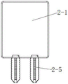
For easy understanding, please refer to fig. 1 to 11, as shown in fig. 1 to 11, the other end of the channel filling block is provided with a mounting hole 2-4, the bottom wall of the reinforcing plate 2-1 is provided with a screw 2-5, and the reinforcing plate 2-1 is fixedly mounted in the mounting hole 2-4 of the channel filling block through the screw 2-5.
Further, the channel filling block 2-3 of the application is of a structure with a high middle part and two low sides. Rainwater falls on the channel filling blocks 2-3 with high middle parts and low two sides so that the rainwater flows to the two sides, and the rainwater flows into the side flow pipeline 1-1.
For easy understanding, please refer to fig. 1 to 11, as shown in fig. 1 to 11, an enclosing protrusion 2-6 is disposed on the outer edge of the other end of the channel gap filling block. The enclosing bulges 2-6 are used for intercepting rainwater and do not overflow to the outside of the channel filling block 2-3.
For easy understanding, referring to fig. 1 to 11, as shown in fig. 1 to 11, irrigation holes 1 to 9 are formed in the bottom wall of the U-shaped box.
For easy understanding, please refer to fig. 1 to 11, as shown in fig. 1 to 11, the water storage device of the present application further includes a water outlet strip, one port of the water outlet strip is disposed inside the U-shaped box body 1 through the irrigation holes 1 to 9, and the other port of the water outlet strip is attached to the outside of the U-shaped box body 1. Specifically, the limiting grooves 1-10 are formed in the outer portion of the U-shaped box body 1, the water outlet strips can be fixed in the limiting grooves 1-10, and the water outlet strips are used for enabling water in the U-shaped box body 1 to slowly permeate into soil and provide moisture for plant roots.
The water storage device of this application still includes the supporting network, and the shape of supporting network and the cross-sectional shape phase-match of U type box 1, the supporting network is fixed on the surface of U type box 1. The supporting net is also U-shaped, the inner edge of the top end of the U-shaped box body 1 can be provided with a supporting strip, and the supporting net is placed on the supporting strip, so that the supporting net is fixed on the surface of the U-shaped box body 1.
Further, the supporting net of the water storage device is provided with micropores through which water can pass but sand cannot pass.
For easy understanding, please refer to fig. 12, fig. 12 is a structural diagram of a grid structure provided in an embodiment of the present application, and as shown in fig. 12, a support grid of a water storage device of the present application is provided with a grid structure 3 and a separation material layer, the separation material layer is fixed on a surface of the grid structure 3, and the separation material layer is a material layer through which water can pass and sand can not pass.
The application provides a tree planting device, which comprises a water storage device, a water collecting tray 4 and an evaporation preventing part 5;
the evaporation-proof part 5 is fixed at the mouth 1-7 of the cylindrical tree planting cavity of the water storage device;
the water collecting tray 4 is fixed on the evaporation preventing member 5 so that the water collecting tray 4 covers the surface of the water storage means through the evaporation preventing member 5. Specifically, the water collecting tray 4 is fixedly covered on the surfaces of the U-shaped box body 1 and the connecting piece 2.
For easy understanding, please refer to fig. 13 to 16, fig. 13 is a structural diagram of a water collecting tray provided in the embodiment of the present application, fig. 14 is an anatomical structural diagram of the water collecting tray provided in the embodiment of the present application, fig. 15 is a structural diagram of an evaporation preventing member provided in the embodiment of the present application, fig. 16 is an anatomical structural diagram of an evaporation preventing member provided in the embodiment of the present application, as shown in fig. 13 to 16, the water collecting tray 4 includes a body, a water guiding strip 4-2 and a mounting opening 4-1, the mounting opening 4-1 is disposed at the center of the body, the water guiding strip 4-2 is disposed on the surface of the body, and the water guiding strip 4-2 makes the surface of the body form a structure with high periphery and low center, rainwater falls on the surface of the water collecting tray 4, the water guiding strip 4-2 is used for guiding rainwater from the surface of the water collecting tray 4 to the mounting opening 4-1, the edge of the mounting opening 4-1 is provided with a mounting insert 4-, the installation inserting sheet 4-3 is connected with the outer wall of the evaporation-proof part 5.
For easy understanding, please refer to fig. 13-16, as shown in fig. 1-16, the evaporation-proof member 5 includes an outer wall 5-1 and an inner wall 5-3, the outer wall 5-1 is a gradually expanding truncated cone, the inner wall 5-3 is a cylinder body matching with the cylindrical tree planting cavity 1-4, and the top end of the outer wall 5-1 is connected with the top end of the inner wall 5-3; the inner wall 5-3 is provided with a limiting T-shaped buckle 5-4, the outer wall 5-1 is provided with a mounting groove 5-2 matched with the mounting inserting sheet 4-3, the mounting inserting sheet 4-3 is inserted in the mounting groove 5-2, the outer wall 5-1 is provided with a water guide opening 5-5, so that the water collecting tray 4 is fixed on the evaporation-proof part 5, rainwater flows into the mounting opening 4-1 from the water guide strip 4-2 of the water collecting tray 4, and the rainwater can flow into the two side flow pipelines 1-1 and the bottom flow pipeline 1-2 from the water guide opening 5-5.
Wherein, the tray 4 that catchments encloses into the environment of relative sealing with soil, weakens the evaporation of the peripheral soil moisture of plant, has promoted the absorption rate to water of plant, has carried out abundant utilization to moisture, has solved the problem that the survival rate of plant is low, the growth is difficult because the lack of water leads to under the adverse circumstances, but wide application in the cultivation of sapling and the transplantation field of trees or vegetation, is applicable to and carries out the afforestation on desert, sand land, desolate and early, rock.
Furthermore, the side wall of the mouth 1-7 of the quasi-cylindrical tree planting cavity of the water storage device is provided with a limiting groove 1-11 matched with a limiting T-shaped buckle 5-4, and the limiting T-shaped buckle 5-4 is inserted into the limiting groove 1-11, so that the evaporation preventing part 5 is fixed in the mouth 1-7 of the quasi-cylindrical tree planting cavity.
Further, the evaporation prevention member 5 of the present application may be manufactured in one piece.
Furthermore, the tree planting device of the application further comprises a protective cover, the protective cover comprises a columnar body matched with the quasi-cylindrical tree planting cavity 1-4, the protective cover is arranged inside the quasi-cylindrical tree planting cavity 1-4, and the protective cover protrudes out of a cavity opening 1-7 of the quasi-cylindrical tree planting cavity.
Furthermore, the protective cover is provided with air holes.
The protective cover wraps the stem of the plant to be planted and is used for protecting the plant to be planted from being eroded by wind and sand, so that the plant is prevented from being eroded by the wind and sand in arid or semi-arid regions, and the growth of the plant is protected.
The application provides a tree planting method, which applies a tree planting device and comprises the following steps: digging a device pit for placing a tree planting device, wherein the depth of the device pit is smaller than the height of the water storage device; digging a tree planting pit for planting trees in the middle of the device pit; putting the roots of the plants to be planted into the planting tree pits, and filling the planting tree pits with soil; the stems of plants to be planted are arranged in the quasi-cylindrical tree planting cavities 1-4 through trunk channels 1-6, the arc-shaped filling blocks 2-2 are fixed at the gaps of the long gaps 1-3, the channel filling blocks 2-3 are fixed at the top ends of the trunk channels 1-6, and the water storage device is fixed by filling the holes of the device pits with soil; enclosing the evaporation-proof part 5 on the stem of the plant to be planted, and fixedly arranging the evaporation-proof part on the cavity opening 1-7 of the quasi-cylindrical tree planting cavity; the water collecting tray 4 is fixed on the water storage device so that the water collecting tray 4 covers the evaporation preventing member 5 and the edge of the water collecting tray 4 is fixed with soil. Therefore, rainwater can flow to the water storage device through the water collecting tray 4, the evaporation preventing part 5 can also prevent water in the water storage device from evaporating from the mounting opening 4-1 of the water collecting tray 4, and the tree planting device can effectively collect rainwater to irrigate the roots of plants.
The terms "first," "second," "third," "fourth," and the like in the description of the application and the above-described figures, if any, are used for distinguishing between similar elements and not necessarily for describing a particular sequential or chronological order. It is to be understood that the data so used is interchangeable under appropriate circumstances such that the embodiments of the application described herein are, for example, capable of operation in sequences other than those illustrated or otherwise described herein. Furthermore, the terms "comprises," "comprising," and "having," and any variations thereof, are intended to cover a non-exclusive inclusion, such that a process, method, system, article, or apparatus that comprises a list of steps or elements is not necessarily limited to those steps or elements expressly listed, but may include other steps or elements not expressly listed or inherent to such process, method, article, or apparatus.
It should be understood that in the present application, "at least one" means one or more, "a plurality" means two or more. "and/or" for describing an association relationship of associated objects, indicating that there may be three relationships, e.g., "a and/or B" may indicate: only A, only B and both A and B are present, wherein A and B may be singular or plural. The character "/" generally indicates that the former and latter associated objects are in an "or" relationship. "at least one of the following" or similar expressions refer to any combination of these items, including any combination of single item(s) or plural items. For example, at least one (one) of a, b, or c, may represent: a, b, c, "a and b", "a and c", "b and c", or "a and b and c", wherein a, b, c may be single or plural.
The above embodiments are only used for illustrating the technical solutions of the present application, and not for limiting the same; although the present application has been described in detail with reference to the foregoing embodiments, it should be understood by those of ordinary skill in the art that: the technical solutions described in the foregoing embodiments may still be modified, or some technical features may be equivalently replaced; and such modifications or substitutions do not depart from the spirit and scope of the corresponding technical solutions in the embodiments of the present application.