Detailed Description
Hereinafter, embodiments of the present invention will be described with reference to the drawings.
A measuring apparatus according to an embodiment of the present invention will be described with reference to fig. 1 to 3.
In fig. 1, reference numeral 1 denotes a measuring device system, and O denotes a distance measuring optical axis in a state where the optical axis is not deflected, and the distance measuring optical axis at this time is taken as a reference optical axis.
The measuring apparatus system 1 mainly includes a tripod 2 as a support apparatus, a measuring apparatus 3, and a setting table unit 4 as a support portion of the measuring apparatus 3.
The installation table unit 4 is attached to an upper end of the tripod 2, and the measuring device 3 is supported by the installation table unit 4 so as to be rotatable in the vertical direction and the horizontal direction.
As shown in fig. 2, the installation table unit 4 includes a base 5 fixed to the upper end of the tripod 2, a horizontal base 6 fixedly attached to the base 5, and a bracket portion 7 provided to the horizontal base 6 so as to be rotatable in the horizontal direction. The measuring device 3 is rotatably attached to the bracket portion 7 in the vertical direction.
A horizontal rotation shaft 8 protrudes from the lower surface of the bracket portion 7. The horizontal rotary shaft 8 is rotatably fitted to the horizontal base 6 via a bearing (not shown). The bracket portion 7 is rotatable in the horizontal direction about the horizontal rotation shaft 8.
A horizontal angle detector 9 (e.g., an encoder) for detecting a horizontal angle (an angle in a rotation direction around the horizontal rotation axis 8) is provided between the horizontal rotation axis 8 and the horizontal base 6. The horizontal angle detector 9 detects a relative rotation angle of the bracket portion 7 with respect to the horizontal direction of the horizontal base 6.
A horizontal rotary gear 11 is fixed to the horizontal base 6 concentrically with the horizontal rotary shaft 8, and a horizontal pinion gear 12 is engaged with the horizontal rotary gear 11. The bracket portion 7 is provided with a horizontal motor 13, and the horizontal pinion gear 12 is fixed to an output shaft of the horizontal motor 13.
The horizontal pinion gear 12 is rotated by driving of the horizontal motor 13, and the horizontal pinion gear 12 revolves around the horizontal rotary gear 11. The bracket 7 and the measuring device 3 are integrally rotated around the horizontal rotation shaft 8 by the revolution of the horizontal pinion gear 12. Then, the measuring device 3 is rotated in the horizontal direction by the horizontal motor 13.
The measuring device 3 is supported by the bracket portion 7 via a vertical rotation shaft 14. The measuring device 3 is rotatable in the vertical direction about the vertical rotation shaft 14 extending in the horizontal direction.
The vertical rotation gear 15 is fixed to one end of the vertical rotation shaft 14, and the vertical pinion gear 16 is engaged with the vertical rotation gear 15. The vertical pinion gear 16 is fixed to an output shaft of a vertical motor 17 provided in the bracket portion 7. The vertical pinion gear 16 is rotated by driving the vertical motor 17. Further, the measurement device 3 is rotated in the vertical direction by the vertical motor 17 via the vertical rotation gear 15 and the vertical rotation shaft 14.
Further, a vertical angle detector 18 (for example, an encoder) for detecting a lead right angle (an angle in a rotational direction around the vertical rotation shaft 14) is provided between the vertical rotation shaft 14 and the bracket portion 7. The vertical angle detector 18 detects a relative rotation angle of the measuring device 3 with respect to the vertical direction of the bracket portion 7.
The horizontal motor 13 and the vertical motor 17 are driven by a second motor driver 32 (described later), and are driven and controlled by an arithmetic control unit 26 (described later) as a control unit via the second motor driver 32 so as to be rotated by a required amount at a required timing.
The rotation amount of the horizontal motor 13 (i.e., the horizontal angle of the bracket portion 7) is detected by the horizontal angle detector 9. The amount of rotation of the vertical motor 17 (i.e., the lead angle of the measuring device 3) is detected by the lead angle detector 18.
Then, the horizontal angle and the vertical angle of the measuring device 3 are detected by the horizontal angle detector 9 and the vertical angle detector 18, respectively, and the detection results are input to the arithmetic control unit 26, respectively. Further, the horizontal motor 13 and the vertical motor 17 constitute a rotation driving unit.
The horizontal angle detector 9 and the vertical angle detector 18 constitute a direction angle detector as an angle detector for detecting a vertical rotation angle and a horizontal rotation angle of the measuring device 3.
The measuring device 3 is further described with reference to fig. 3 and 4.
The surveying instrument 3 mainly includes a distance measuring light emitting unit 21, a light receiving unit 22, a tracking unit 23, a wide angle imaging unit 24, a distance measuring calculation unit 25, the calculation control unit 26, a storage unit 27, a posture detection unit 28, an emission direction detection unit 29, a first motor driver 31, a second motor driver 32, an imaging control unit 33, an image processing unit 34, a display unit 35, an optical axis deflecting unit 36, and a tracking calculation unit 37. These components are housed in and integrated with the frame 39. The distance measuring light emitting unit 21, the light receiving unit 22, the distance measuring calculation unit 25, the optical axis deflecting unit 36, and the like constitute a distance measuring unit 38 having a function as an optical distance meter.
The distance measurement arithmetic unit 25 and the arithmetic control unit 26 are implemented by a CPU, a general-purpose CPU, an embedded CPU, a microprocessor, or the like, which is used exclusively in the present embodiment. As the storage unit 27, a semiconductor memory such as a RAM, a ROM, a flash ROM, or a DRAM, a magnetic recording memory such as an HDD, or an optical recording memory such as a CDROM is used.
The storage unit 27 stores various programs for executing the present embodiment, and the distance measurement calculation unit 25 and the calculation control unit 26 develop and execute the stored programs, respectively. The storage unit 27 stores various data such as measurement data and image data.
The arithmetic control unit 26 controls the optical axis deflecting unit 36 via the first motor driver 31. Furthermore, the deflection of the distance measurement optical axis is controlled by the optical axis deflecting unit 36, and the distance measurement computing unit 25, the imaging control unit 33, and the tracking computing unit 37 are controlled in a unified manner, and synchronous control of distance measurement, imaging, and tracking is performed.
The posture detecting unit 28 detects the inclination of the measuring device 3 with respect to the horizontal or vertical direction, and the detection result is input to the arithmetic and control unit 26. Further, as the posture detecting unit 28, a tilt detector such as a tilt sensor can be used, and further, a posture detecting device disclosed in japanese patent application laid-open No. 2016-151423 can be used. The attitude detection device disclosed in japanese patent application laid-open No. 2016-151423 can detect a tilt of 360 ° or more in all directions in real time.
The distance measuring light emitting unit 21 has an emission optical axis 41, and a light emitting element 42, such as a Laser Diode (LD), is provided on the emission optical axis 41. An illumination lens 43 is provided on the outgoing optical axis 41. The exit optical axis 41 is deflected so as to coincide with the light receiving optical axis 45 by a beam splitter 44 serving as a deflecting optical member provided on the exit optical axis 41 and a mirror 46 serving as a deflecting optical member provided on the light receiving optical axis 45 (described later). The reflector 46 has a shape substantially equal to or slightly larger than the beam diameter of the distance measuring beam 47, and has a size substantially equal to the wavelength dispersion compensating prisms 65 and 68 (described later). The reflecting mirror 46 and the chromatic dispersion compensating prisms 65 and 68 occupy a limited portion centered on the light receiving optical axis 45.
The aforementioned beam splitter 44 may be a half mirror, but is preferably a polarization beam splitter having polarization optical characteristics. For example, the beam splitter 44 has an optical characteristic of reflecting S-polarized light and transmitting P-polarized light.
The beam splitter 44 and the mirror 46 constitute an output optical axis deflecting unit.
The light emitting element 42 emits a pulse of laser light or emits burst of laser light. The distance measuring light emitting unit 21 emits the pulse laser beam (or burst-emission laser beam) emitted from the light emitting element 42 as the distance measuring light 47. Further, Japanese patent application laid-open No. 2016-161411 discloses burst emission.
The light-receiving unit 22 will be described. The reflected distance measuring light 48 from the object to be measured is incident on the light receiving unit 22. The light receiving unit 22 has the light receiving optical axis 45, and the outgoing optical axis 41 deflected by the beam splitter 44 and the mirror 46 coincides with the light receiving optical axis 45.
The state where the outgoing optical axis 41 and the light receiving optical axis 45 coincide is referred to as a distance measuring optical axis 49 (see fig. 1).
The optical axis deflecting unit 36 is disposed on the reference optical axis O. The reference optical axis O is a straight optical axis passing through the center of the optical axis deflecting unit 36. The reference optical axis O coincides with the outgoing optical axis 41, the light receiving optical axis 45, the tracking optical axis 54 (described later), and the distance measuring optical axis 49 when the optical axis deflecting unit 36 does not deflect the optical axis.
An imaging lens 51 is disposed on the light receiving optical axis 45 that passes through the optical axis deflecting unit 36. Further, a light receiving element 52 is provided on the aforementioned light receiving optical axis 45. The light receiving element 52 is, for example, a Photodiode (PD), an Avalanche Photodiode (APD), or a similar photoelectric conversion element.
The aforementioned imaging lens 51 images the aforementioned reflected distance measuring light 48 onto the aforementioned light receiving element 52. The light receiving element 52 receives the reflected distance measuring light 48 and generates a light reception signal. The light reception signal is input to the distance measurement computing unit 25. The distance measurement computing unit 25 measures a distance to a measurement target (light wave distance measurement) based on the signal of the distance measurement light 47 and the signal of the reflected distance measurement light 48. As the signal of the distance measuring light 47 and the signal of the reflected distance measuring light 48, various signals such as a light emission timing signal of the distance measuring light 47 and a light reception timing signal of the reflected distance measuring light 48, or a phase signal of the distance measuring light 47 and a phase signal (phase difference signal) of the reflected distance measuring light 48 can be used.
As the measurement, prism measurement in which the measurement object has retroreflectivity (retroreflective property) or non-prism measurement in which the measurement object does not have retroreflectivity is performed.
The light receiving unit 22 is constituted by the optical axis deflecting unit 36, the imaging lens 51, the light receiving element 52, and the like.
The following unit 23 will be explained. The tracking unit 23 has the tracking optical axis 54, and a tracking light source 55, a reflecting mirror 58, a separating mirror 59, the imaging lens 51, the reflecting mirror 46, and the optical axis deflecting unit 36 are disposed on the tracking optical axis 54. The tracking optical axis 54 is deflected by the reflecting mirror 58 and the separating mirror 59 so as to coincide with the light receiving optical axis 45 and the distance measuring optical axis 49. Here, the imaging lens 51 is used as an illumination lens in the tracking unit 23.
As the tracking light source 55 for emitting the tracking light 57, a light source such as a Laser Diode (LD) is used. Preferably, the tracking light 57 and the distance measuring light 47 have the same wavelength. The tracking light 57 is red to near infrared light, for example, light having a wavelength band in the range of 650nm to 850 nm. Alternatively, light including light in a wavelength band in a range of 650nm to 850nm is used. Further, as the tracking light source 55, the light emitted from the laser diode may be guided by an optical fiber, and the emission end face of the optical fiber may be used as the tracking light source. As the optical characteristics of the tracking light 57, unpolarized light (light having no polarization characteristics) is used.
The separating mirror 59 may be a half mirror, but may be an unpolarized light separating mirror having different amounts of transmitted light and reflected light. The light amount ratio of the transmitted light amount to the reflected light amount can be appropriately set in accordance with the performance required of the measurement device. For example, the transmitted light amount: amount of reflected light = 7: 3. in order to prevent a decrease in the amount of distance measurement light, it is preferable to use a polarization beam splitter that reflects S-polarized light for the beam splitter 44.
Further, when the beam splitter 44 is a polarization beam splitter, the polarization characteristics of the distance measuring light 47 and the tracking light 57 are different. For example, the distance measuring light 47 emitted from the light emitting element 42 is S-polarized light, and the tracking light 57 emitted from the tracking light source 55 is unpolarized light.
In this case, the tracking light 57 emitted from the tracking light source 55 is partially reflected by the separation mirror 59 (e.g., 3/10). Since the reflected tracking light is unpolarized light and the beam splitter 44 is a polarization beam splitter, the reflected tracking light transmits 50% of the reflected tracking light through the beam splitter 44. The distance measuring light of the S-polarized light emitted from the light emitting element 42 is totally reflected by the beam splitter 44, and the reflected distance measuring light portion (for example, 7/10) reflected by the measurement object passes through the separating mirror 59.
The tracking light 57 is made into a parallel beam by the imaging lens 51, passes through the optical axis deflecting unit 36, and is irradiated coaxially with the distance measuring light 47. The reflected tracking light reflected by the object to be measured enters the optical axis deflecting unit 36 on the same optical axis as the reflected distance measuring light 48 (i.e., the distance measuring optical axis 49), passes through the optical axis deflecting unit 36, and is reflected by the reflecting mirror 46.
The mirror 46 separates the tracking light receiving optical axis 54' from the distance measuring optical axis 49. The beam splitter 44 is disposed on the tracking light receiving optical axis 54 ', and an imaging lens 56 and a tracking image pickup device 61 are disposed on the tracking light receiving optical axis 54'. That is, the tracking light receiving optical axis 54 and the distance measuring optical axis 49 share a part.
The tracking image sensor 61 is a CCD or CMOS sensor that is an aggregate of pixels, and the position of each pixel on the image element can be specified. For example, each pixel has a pixel coordinate in a coordinate system with the aforementioned tracking light receiving optical axis 54' as an origin, and a position on the image element is determined by the pixel coordinate.
The tracking image pickup device 61 receives the reflected tracking light reflected by the measurement object, and outputs a light reception signal, which is input to the tracking calculation unit 37. The light reception signal is emitted for each pixel, and the light reception signal emitted from each pixel has position information. The tracking calculation unit 37 calculates tracking control information necessary for tracking based on the light receiving position of the reflected tracking light on the tracking image sensor 61. For example, the deviation of the image center of the narrow-angle image from the light receiving position is calculated.
A part of the functions of the arithmetic control unit 26 may be assigned to the tracking arithmetic unit 37. Alternatively, the tracking calculation unit 37 may be a CPU, an embedded CPU, a microprocessor, or the like.
The tracking control information is information for calculating a deviation and a direction of the deviation between the position of the tracking light receiving optical axis 54 'and the position of the light receiving position on the tracking image sensor 61, and matching the position of the light receiving position with the tracking light receiving optical axis 54', for example. The tracking control information includes control information of the optical axis deflecting unit 36 for controlling the rotation amount and the rotation direction of each of the disc prisms 63 and 64 (described later) based on the calculation result of the positional deviation and the direction of the deviation of the light receiving position.
The tracking calculation unit 37 inputs tracking control information to the calculation control unit 26. The arithmetic control unit 26 controls the rotation of the disc prisms 63 and 64 based on tracking control information to perform tracking. The tracking calculation unit 37 may perform tracking based on a tracking control signal.
The tracking light source 55, the reflecting mirror 58, the separating mirror 59, the imaging lens 51, the optical axis deflecting unit 36, the beam splitter 44, the imaging lens 56, the tracking image pickup device 61, the tracking calculation unit 37, and the like constitute the tracking unit 23.
The tracking light 57 and the background light including the measurement object are incident on the tracking unit 23. The tracking image pickup device 61 receives the tracking light 57 and the background light to acquire a background image including a measurement target. Therefore, the tracking unit 23, the tracking imaging element 61, and the like can function as the narrow-angle imaging unit 88 for acquiring the background image of the measurement point portion. In this case, the tracking optical axis 54 and the tracking light receiving optical axis 54' are equal to the narrow-angle imaging optical axis of the narrow-angle imaging unit 88. Further, only the background light transmitted through the chromatic dispersion compensating prisms 65 and 68 described later is incident on the tracking imaging element 61. That is, the narrow-angle photographing optical axis shares a part with the distance measuring optical axis 49.
Then, the tracking unit 23 may also serve as the narrow-angle imaging unit 88, and the image obtained from the tracking imaging element 61 may be acquired as a narrow-angle image, and the narrow-angle image may be acquired as a background image of the aimed position (measurement point) of the distance measurement optical axis 49. The center of the narrow-angle image (image center) is the measurement point on the distance measurement optical axis 49.
Further, in a state where the tracking is performed with the tracking unit 23 also serving as the narrow-angle imaging unit 88, the tracking light source 55 is turned on to irradiate the tracking light 57. The tracking camera 61 receives the reflected tracking light and the background light. Therefore, the tracking unit 23 can acquire a tracking image in a tracking state. In the untracked state, the tracking light source 55 may be turned off to receive the background light at the aiming position. In this case, the tracking unit 23 functions only as the narrow-angle imaging unit 88 and acquires a narrow-angle background image in the aiming direction (the direction of the distance measuring optical axis 49).
The narrow-angle imaging unit 88 receives the limiting beam near the tracking light reception optical axis 54' that passes through the chromatic dispersion compensating prisms 65 and 68 that are the central portion of the optical axis deflecting unit 36 and is reflected by the reflecting mirror 46. The narrow-angle imaging unit 88 has a narrow angle of view of, for example, about 3 °, and the narrow-angle image has a deep focal depth. Therefore, the narrow-angle imaging unit 88 can omit or simplify the focusing mechanism, and can acquire an image of a distance measurement range with a single focus.
The optical axis deflecting unit 36 will be described with reference to fig. 4, 5 (a), and 5 (B).
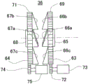
The optical axis deflecting unit 36 is constituted by a pair of the aforementioned disc prisms 63 and 64. The disc prisms 63 and 64 are each in the shape of a circular plate having the same diameter, and are concentrically arranged on the light receiving optical axis 45 (the distance measuring optical axis 49) so as to be orthogonal to the light receiving optical axis 45 and are arranged in parallel at a predetermined interval. The disc-shaped prism 63 is formed of optical glass. Further, as a basic configuration, the disc prism 63 has a plurality of prism columns arranged in parallel and a chromatic dispersion compensating prism 65 arranged at the center. The chromatic dispersion compensating prism 65 is a composite prism in which an optical prism 65a and an optical prism 65b are bonded. In the figure, the disc-shaped prism 63 has 3 prism columns (for example, a rod-shaped triangular prism, hereinafter referred to as a triangular prism) 66a, 66b, and 66 c. Further, the disc prisms 63 and 64 (the chromatic dispersion compensating prisms 65 and 68) are provided on a common optical axis of the distance measuring optical axis 49 and the narrow-angle imaging optical axis.
Also, the aforementioned disc-shaped prism 64 is formed of optical glass. Further, as a basic configuration, the disc prism 64 has 3 prism columns (for example, a rod-shaped triangular prism, hereinafter referred to as a triangular prism) 67a, 67b, and 67c arranged in parallel, and further has a chromatic dispersion compensating prism 68 arranged at the center. The chromatic dispersion compensating prism 68 is a composite prism in which an optical prism 68a and an optical prism 68b are bonded to each other. The triangular prisms 66a, 66b, and 66c and the triangular prisms 67a, 67b, and 67c all have optical deflection characteristics with the same deflection angle. The optical deflection characteristics of the chromatic dispersion compensating prisms 65 and 68 are also made to be the same as those of the triangular prisms 66a, 66b, and 66c and the triangular prisms 67a, 67b, and 67 c.
The chromatic dispersion compensating prism 65 and the chromatic dispersion compensating prism 68 have the same structure and are disposed in point symmetry. The sizes of the chromatic dispersion compensating prisms 65 and 68 (the lengths of the triangular prisms 66a and 67a in the longitudinal direction and the width direction) are larger than the beam diameters of the distance measuring light 47 and the tracking light 57, and the distance measuring light 47 and the tracking light 57 only pass through the chromatic dispersion compensating prisms 65 and 68. Further, the axial length (optical axis length) of the chromatic dispersion compensating prisms 65, 68 is longer than the triangular prisms 66a, 66b, 66 c. That is, the chromatic dispersion compensating prisms 65 and 68 protrude from the disc prisms 63 and 64 in the axial direction.
The width of the triangular prisms 66a and 67a may be equal to the width of the chromatic dispersion compensating prisms 65 and 68, or may be larger than the chromatic dispersion compensating prisms 65 and 68. The triangular prisms 66a and 67a are two-part triangular prisms having the same width as the chromatic dispersion compensating prisms 65 and 68, and sandwich the chromatic dispersion compensating prisms 65 and 68 therebetween.
The chromatic dispersion compensating prisms 65 and 68 are distance measuring light deflecting sections through which the distance measuring light 47 is transmitted and emitted. In addition, the portions other than the chromatic dispersion compensating prisms 65 and 68 (both end portions of the triangular prisms 66a and 67a, the triangular prisms 66b and 66c, and the triangular prisms 67b and 67 c) are reflected distance measuring light deflecting portions through which the reflected distance measuring light 48 passes and enters.
The disc prisms 63 and 64 are arranged to be independently rotatable around the light receiving optical axis 45. The disc prisms 63 and 64 are configured to deflect the outgoing optical axis 41 of the outgoing distance measuring light 47 in an arbitrary direction by independently controlling the rotation direction, the rotation amount, and the rotation speed. The disc prisms 63 and 64 deflect the light reception optical axis 45 of the reflected distance measuring light 48 received in parallel with the emission optical axis 41.
The outer shapes of the disc prisms 63 and 64 are circular shapes centered on the light receiving optical axis 45 (reference optical axis O). In addition, the diameters of the disc-shaped prisms 63 and 64 are set so that a sufficient amount of light can be obtained in consideration of the spread of the reflected distance measuring light 48.
A ring gear 69 is fitted around the outer periphery of the disc prism 63, and a ring gear 71 is fitted around the outer periphery of the disc prism 64.
The drive gear 72 meshes with the ring gear 69, and the drive gear 72 is fixed to an output shaft of the motor 73. Similarly, a drive gear 74 meshes with the ring gear 71, and the drive gear 74 is fixed to an output shaft of the motor 75. The motors 73 and 75 are electrically connected to the first motor driver 31. The motors 73 and 75 constitute a rotation driving unit of the optical axis deflecting unit 36.
As the motors 73 and 75, motors capable of detecting a rotation angle or motors that rotate in accordance with a drive input value, such as pulse motors, are used. Alternatively, the rotation amount of the motors 73 and 75 may be detected by using a rotation angle detector (e.g., an encoder) that detects the rotation amount (rotation angle) of the motors. The rotation amounts of the motors 73 and 75 are detected, respectively, and the arithmetic control unit 26 controls the motors 73 and 75 individually via the first motor driver 31. Further, encoders may be directly attached to the ring gears 69 and 71, respectively, and the rotational angles of the ring gears 69 and 71 may be directly detected by the encoders.
The drive gears 72 and 74 and the motors 73 and 75 are provided at positions not interfering with other components such as the distance measuring light emitting unit 21, for example, below the ring gears 69 and 71.
As shown in fig. 5B, the chromatic dispersion compensating prism 65 is configured by bonding 2 optical prisms 65a and 65B having different wavelength characteristics (dispersion amount and refractive index). The chromatic dispersion compensating prism 65 may be configured as an achromatic prism for obtaining only red and near-infrared images by bonding 3 or more optical prisms having different wavelength characteristics. The optical prisms 65a and 65b may be made of optical glass or optical plastic, or may be made of a combination of optical glass and optical plastic.
Similarly, as shown in fig. 5B, the chromatic dispersion compensating prism 68 is configured by bonding 2 optical prisms 68a and 68B having different wavelength characteristics (dispersion amount and refractive index). The chromatic dispersion compensating prism 68 may be configured as an achromatic prism for obtaining only red and near-infrared images by bonding 3 or more optical prisms having different wavelength characteristics. Further, as the optical prisms 68a and 68b, optical glass or optical plastic is used, and further, a combination of optical glass and optical plastic may be used.
As shown in fig. 7, when the light (for example, background light) 62 of a predetermined wavelength band sequentially passes through the chromatic dispersion compensating prisms 65 and 68, the light 62 dispersed by the optical prism 65a is sequentially inversely dispersed by the optical prism 65b, the optical prism 68a, and the optical prism 68 b. That is, the light 62 dispersed by the chromatic dispersion compensating prism 65 is inversely dispersed by the chromatic dispersion compensating prism 68, and the dispersion action of the chromatic dispersion compensating prism 65 is cancelled by the chromatic dispersion compensating prism 68. Therefore, the chromatic dispersion of the light 62 that sequentially transmits the chromatic dispersion compensating prisms 65, 68 is suppressed.
In the present embodiment, the chromatic dispersion compensating prisms 65 and 68 have a function of compensating chromatic dispersion of the tracking light reflected by the object to be measured (reflected tracking light) or the background light for obtaining a narrow-angle image for aiming (described later). For example, the chromatic dispersion compensating prisms 65 and 68 transmit light in a wavelength band of 650nm to 850nm (red to near infrared) among the reflected tracking light and the background light, and perform chromatic dispersion compensation.
Fig. 6 is a graph showing an example of an error in the wavelength of light such as reflected tracking light when the off-angle between the distance measurement optical axis 49 and the tracking optical axis 54 is 30 °. In fig. 6, 81 shows an error in the case of using a normal prism (triangular prism), and 82 shows an error in the case of using the chromatic dispersion compensating prisms 65 and 68.
As shown in fig. 6, in the case of a general prism, when light having a wavelength of about 800nm is used, since the light has a single wavelength, an error is hardly generated (dispersion is not generated). However, in the case of a normal prism, when a wavelength band of light to be used is enlarged, an error is significantly increased (dispersion occurs). For example, when an image is obtained using light in a wavelength band of 650nm to 850nm, large dispersion occurs in a range of about-400.0 to 1400.0 seconds, and the obtained image is a largely blurred image. In order to reduce the blur, it is necessary to narrow the wavelength band and reduce the dispersion. In this case, since a sufficient amount of light cannot be obtained and a dark image is obtained, it is necessary to increase the exposure time so as to obtain a sufficient amount of light and obtain a bright image.
On the other hand, when the chromatic dispersion compensating prisms 65 and 68 are used, the chromatic dispersion can be reduced to a range of-100.0 to 0.0 seconds even in a wavelength band of 650nm to 850 nm. Therefore, even if the exposure time is short, a fine image with a sufficient light amount and less blur can be obtained, and accurate aiming and image tracking can be achieved.
The illumination lens 43, the beam splitter 44, the mirror 46, the distance measuring light deflecting unit (first optical axis deflecting unit), and the like constitute a distance measuring illumination optical system. The separation mirror 59, the imaging lens 51, the reflection distance measuring light deflecting unit (second optical axis deflecting unit), and the like constitute a tracking illumination optical system. The distance measuring light deflecting unit (first optical axis deflecting unit), the imaging lens 56, and the like constitute a tracking light receiving optical system.
The distance measuring operation unit 25 controls the light emitting element 42 to emit a laser beam in a pulse or burst (intermittent) manner as the distance measuring light 47. The distance measuring light 47 is deflected by the wavelength dispersion compensation prisms 65 and 68 (distance measuring light deflecting unit) toward the outgoing optical axis 41 to be measured. The distance measurement is performed in a state where the distance measurement optical axis 49 is aimed at the measurement target.
The reflected distance measuring light 48 reflected from the measurement object is incident through the triangular prisms 66b and 66c, the triangular prisms 67b and 67c (reflected distance measuring light deflecting unit), and the imaging lens 51, and is received by the light receiving element 52. The light receiving element 52 sends out a light reception signal to the distance measurement computing unit 25, and the distance measurement computing unit 25 performs distance measurement of a measurement point (a point at which distance measurement light is irradiated) for each pulse light based on the light reception signal from the light receiving element 52. The distance measurement data is stored in the storage unit 27.
The emission direction detection unit 29 counts the number of drive pulses input to the motors 73 and 75 to detect the rotation angles of the motors 73 and 75. Alternatively, the emission direction detection unit 29 detects the rotation angle of the motors 73 and 75 based on a signal from an encoder. The emission direction detection unit 29 calculates the rotational positions of the disc prisms 63 and 64 based on the rotational angles of the motors 73 and 75. Further, the emission direction detector 29 calculates the deflection angle and the emission direction of the distance measuring light 47 for each pulse light based on the refractive index and the rotational position of the disc prisms 63 and 64. The calculation result (angle measurement result) is input to the calculation control unit 26 in association with the distance measurement result. When the distance measuring light 47 is burst-emitted, distance measurement is performed for each intermittent distance measuring light.
The arithmetic control unit 26 can control the amount and direction of the distance measuring optical axis 49 deflected by the optical axis deflecting unit 36 by controlling the amount and direction of rotation of the motors 73 and 75, respectively. The arithmetic control unit 26 can dynamically control the deflecting action by the optical axis deflecting unit 36 by controlling the rotation direction and the rotation speed of each of the motors 73 and 75 and the rotation ratio between the motors 73 and 75, thereby scanning the distance measuring optical axis 49 in an arbitrary direction and in an arbitrary pattern.
The deflecting action and the scanning action of the optical axis deflecting unit 36 will be described with reference to fig. 4, 5, and 8.
Fig. 4 shows a state in which the triangular prisms 66a, 66b, 66c and the triangular prisms 67a, 67b, 67c are positioned in the same direction, and in this state, the maximum deflection angle (for example, ± 30 °) is obtained. In fig. 5, the disc prisms 63 and 64 are rotated by 180 °, and in this state, the optical actions of the disc prisms 63 and 64 are mutually balanced to obtain the minimum deflection angle (0 °). Therefore, the optical axis of the pulse laser beam (the distance measuring optical axis 49) emitted and received through the disc prisms 63 and 64 coincides with the reference optical axis O.
The distance measuring light 47 is emitted from the light emitting element 42, and the distance measuring light 47 is made into a parallel beam by the illumination lens 43 and emitted toward the measurement object through the distance measuring light deflecting unit (the chromatic dispersion compensating prisms 65 and 68). Here, the distance measuring light 47 is deflected in a desired direction by the chromatic dispersion compensating prisms 65 and 68 and is emitted by transmitting the distance measuring light deflecting unit. Further, since the distance measuring light 47 is a laser beam of a single wavelength or substantially a single wavelength, the dispersion when the distance measuring light passes through the optical axis deflecting unit 36 is small.
The reflected distance measuring light 48 reflected by the measurement object passes through the reflected distance measuring light deflecting unit and enters the imaging lens 51. Further, the reflected distance measuring light 48 is condensed to the light receiving element 52 by the imaging lens 51.
The reflected distance measuring light 48 passes through the reflected distance measuring light deflecting section, whereby the optical axis of the reflected distance measuring light 48 is deflected to coincide with the light receiving optical axis 45 by the triangular prisms 66b, 66c and the triangular prisms 67b, 67 c.
Fig. 8 shows a case where the disc-shaped prism 63 and the disc-shaped prism 64 are relatively rotated. When the direction of deflection of the optical axis by the disc prism 63 is referred to as a deflection a and the direction of deflection of the optical axis by the disc prism 64 is referred to as a deflection B, the deflection of the optical axis by the disc prisms 63, 64 is referred to as an angle difference θ between the disc prisms 63, 64, and becomes a combined deflection C.
The direction and angle of deflection of the emitted distance measuring light 47 can be arbitrarily changed by the combination of the rotational positions of the disc prism 63 and the disc prism 64.
When the disc prism 63 and the disc prism 64 are integrally rotated by the motors 73 and 75 in a state where the positional relationship between the disc prism 63 and the disc prism 64 is fixed (in a state where the offset angle obtained by the disc prism 63 and the disc prism 64 is fixed), the locus (scanning pattern) drawn by the distance measuring light 47 transmitted through the distance measuring light deflecting unit is a circle centered on the reference optical axis O. Further, a desired 2-dimensional closed-loop scanning pattern can be formed by a combination of the rotation of the disc prism 63 and the rotation of the disc prism 64.
The calculation control unit 26 calculates the horizontal angle and the vertical angle of the measurement point with respect to the reference optical axis O based on the deflection angle and the emission direction of the distance measuring light 47, that is, based on the detection result of the emission direction detecting unit 29. Further, the arithmetic control unit 26 can obtain 3-dimensional data of a measurement target by correlating the horizontal angle and the vertical angle with respect to the measurement point with the distance measurement data.
Further, when a direction angle exceeding the maximum deflection angle of the optical axis deflecting unit 36 is required, the distance measuring calculation unit 25 controls the horizontal motor 13 and the vertical motor 17 via the second motor driver 32 to irradiate the distance measuring light 47 to the measurement point.
In this case, the actual horizontal angle and vertical angle (horizontal angle and vertical angle with respect to the horizontal (or vertical)) of the measurement point are determined based on the horizontal angle and vertical angle of the distance measurement optical axis 49 with respect to the reference optical axis O of the measurement point and the horizontal angle and vertical angle of the reference optical axis O with respect to the horizontal (or vertical) detected by the horizontal angle detector 9 and the vertical angle detector 18. Further, the actual horizontal angle and vertical angle can be corrected based on the detection result of the posture detecting unit 28, and thus the correct horizontal angle and vertical angle can be obtained. The 3-dimensional data of the measurement point can be obtained by correlating the corrected horizontal angle and vertical angle with the distance measurement data.
Then, the surveying instrument system 1 functions as a total station.
The wide-angle imaging unit 24 includes an imaging optical axis 76 parallel to the reference optical axis O of the measuring device 3, and an imaging lens 77 and an imaging element 78 disposed on the imaging optical axis 76. The wide-angle imaging unit 24 is a camera having a field angle of 60 ° substantially equal to the maximum deflection angle (e.g., ± 30 °) of the disc prisms 63 and 64, or a field angle larger than the maximum deflection angle (e.g., a field angle of 65 ° to 70 °). The wide-angle imaging unit 24 acquires image data including the maximum deflection range by the optical axis deflecting unit 36.
The relationship between the photographing optical axis 76 and the outgoing optical axis 41 and the reference optical axis O is known. The imaging optical axis 76 is parallel to the outgoing optical axis 41 and the reference optical axis O, and the distance between the optical axes is a known value. The wide-angle imaging unit 24 can acquire a moving image or a continuous image.
The imaging control unit 33 controls the imaging by the wide-angle imaging unit 24. When the wide-angle imaging unit 24 images the moving image or the continuous image, the imaging control unit 33 synchronizes the timing of acquiring the moving image or the frame image constituting the continuous image with the timing of measuring the distance by the measuring device 3. Further, when the image is acquired by the narrow-angle imaging unit 88 (see fig. 3), the timing at which the image is acquired by the narrow-angle imaging unit 88 is synchronized with the timing at which the distance is measured.
The narrow-angle imaging unit 88 acquires an image of the point of irradiation of the distance measuring light 47, and thus functions as a finder of a distance measuring section. Further, since the acquired image is an image of a narrow angle of view (for example, 3 °) in the vicinity of the distance measuring optical axis 49, distortion is small. Further, since the image acquired by the narrow-angle imaging unit 88 is acquired only by the background light transmitted through the chromatic dispersion compensating prisms 65 and 68, chromatic dispersion is compensated, and a fine image with less distortion or blur is acquired.
Here, in the case where the direction of the combined yaw C is set as the Y-axis direction (see fig. 8) with respect to the image obtained by the narrow-angle imaging unit 88, the magnification in the Y-axis direction changes depending on the magnitude of the angular difference θ between the disc prism 63 and the disc prism 64.
Fig. 9 (a) and 9 (B) show a narrow-angle image 92 acquired by the narrow-angle imaging unit 88. Fig. 9 (a) shows a case where the magnification of the narrow-angle image 92 in the Y-axis direction is not changed. Fig. 9 (B) shows a case where the magnification of the narrow-angle image 92 in the Y-axis direction changes and the narrow-angle image 92 is reduced in the Y-axis direction.
Fig. 10 is a graph showing a relationship between the angular difference θ between the disc-shaped prism 63 and the disc-shaped prism 64 and a change in magnification in the Y-axis direction. As shown in fig. 10, in the narrow-angle image 92, as the angle difference θ is larger, the magnification change in the Y-axis direction is larger, and the magnification change in the Y-axis direction is about 20% at the maximum. The relationship between the angular difference θ and the magnification in the Y-axis direction can be known in advance by actual measurement or the like.
The arithmetic control unit 26 also correlates the image with a narrow angle of view (narrow angle image) with the measurement data (distance measurement data and angle measurement data).
The image pickup device 78 is a CCD or CMOS sensor that is an aggregate of pixels, and the position of each pixel on the image pickup device 78 can be specified. For example, each pixel has a pixel coordinate in a coordinate system with the imaging optical axis 76 as an origin, and the position on the imaging element 78 is determined by the pixel coordinate. Further, since the imaging optical axis 76 of the wide-angle imaging unit 24 and the tracking optical axis 54 have a known positional relationship, it is easy to correlate the image (wide-angle image) acquired by the wide-angle imaging unit 24 with the narrow-angle image acquired by the narrow-angle imaging unit 88.
The image processing unit 34 performs image processing such as edge extraction processing, feature point extraction, measurement object detection, image tracking processing, and image matching on the image data acquired by the wide-angle imaging unit 24. The image processing unit 34 creates a grayscale image from the image data. Further, when acquiring the narrow-angle image 92, the image processing unit 34 corrects the narrow-angle image 92 so that the magnification in the Y-axis direction becomes 1, based on the known relationship between the angular difference θ and the magnification in the Y-axis direction.
The display unit 35 displays the image acquired by the wide-angle imaging unit 24, and also displays the narrow-angle image 92 acquired by the narrow-angle imaging unit 88. The display unit 35 divides a display screen, displays a wide-angle image acquired by the wide-angle imaging unit 24 in one portion, and displays the narrow-angle image 92 acquired by the narrow-angle imaging unit 88 in an enlarged manner in another portion.
Alternatively, as shown in fig. 11, the narrow-angle image 92 is superimposed and displayed on the wide-angle image 91. As described above, the reference optical axis O and the photographing optical axis 76 have a known relationship. The position of the measurement point (pixel position) in the wide-angle image 91 is obtained as a field angle with respect to the reference optical axis O. Further, the emission direction detector 29 detects the direction angle of the center of the narrow-angle image 92 with respect to the reference optical axis O (the direction angle of the distance measuring light 47). Therefore, the narrow-angle image 92 can be easily superimposed on the wide-angle image 91 by the angle of view in the wide-angle image 91 and the direction angle of the narrow-angle image 92. By superimposing the narrow-angle image 92 on the wide-angle image 91, it is possible to easily recognize where the measurement object is being measured.
As a method of displaying the images in a superimposed manner, various methods are employed, such as displaying the narrow-angle image 92 on the wide-angle image 91 at the same magnification, displaying the position of the narrow-angle image 92 as a dot, or displaying the narrow-angle image 92 as a mark such as an arrow.
Further, by superimposing the wide-angle image 91 and the narrow-angle image 92 at the same magnification, the image processing unit 34 can correct the distortion of the wide-angle image 91 by the direction angle data of the narrow-angle image 92, and can acquire the wide-angle image 91 with the distortion corrected.
The display unit 35 displays the measurement status, measurement data, and the like. The display unit 35 is a touch panel and also functions as an operation unit. Further, the display unit 35 having a touch panel function may be detachable from the measurement device 3, and remote operation using the display unit 35 may be realized.
The following describes the operation of the measuring apparatus system 1 of the present embodiment. The following operation is realized by the arithmetic control unit 26 executing a program stored in the storage unit 27.
The aforementioned measuring device system 1 is set at a known point (a point whose 3-dimensional coordinates are known) via the aforementioned tripod 2.
The measuring device 3 includes the posture detecting unit 28. The installation posture (inclination) of the measuring device 3 with respect to the horizontal can be detected by the posture detection unit 28. Therefore, the leveling operation of the measuring device 3 is not required. The measurement result is corrected by the tilt detected by the arithmetic control unit 26, and an accurate measurement result is obtained.
The reference optical axis O is directed to a measurement object (measurement point).
As a method for directing the reference optical axis O toward a measurement object (measurement point), the reference optical axis O is aimed at the measurement object in a state where the distance measurement optical axis 49 coincides with the reference optical axis O, that is, in a state where the distance measurement optical axis 49 is not deflected by the optical axis deflecting unit 36. The aiming state is confirmed by the operator by displaying the narrow-angle image 92 captured by the narrow-angle imaging unit 88 on the display unit 35. (in the following description, the following description will be given of a case where the tracking unit 23 is used as the narrow-angle imaging unit 88).
Alternatively, the wide-angle imaging unit 24 is directed to the measurement target to acquire a wide-angle image including the measurement target, and the display unit 35 displays the wide-angle image. Further, the narrow-angle image acquired by the narrow-angle imaging unit 88 is superimposed on the wide-angle image and displayed on the display unit 35, and the deflection caused by the optical axis deflecting unit 36 is adjusted so that the center of the narrow-angle image (the aiming position of the distance measuring light 47) coincides with the measurement target in the wide-angle image. In this case, the deflection angle of the distance measuring light 47 (i.e., the rotation angle of each of the disc prisms 63 and 64) at the time of aiming the distance measuring light 47 is also acquired.
As a method of operating the optical axis deflecting unit 36 to finally aim the distance measuring optical axis 49 at a measuring point, the operator can manually perform the operation from the display unit 35 while checking the display of the display unit 35. Alternatively, the measurement target may be detected by the image processing unit 34, and the arithmetic control unit 26 may automatically perform the detection based on the detection result.
Here, the chromatic dispersion of the background light is suppressed by the chromatic dispersion compensating prisms 65 and 68, and the magnification in the Y-axis direction is corrected by the image processing unit 34, with respect to the narrow-angle image 92. Therefore, the fine narrow-angle image 92 with a sufficient amount of light and with less blur or distortion can be obtained, and the sighting and the confirmation of the sighting can be easily performed.
The distance measurement is performed at a time point when the distance measurement optical axis 49 is aimed at a measurement point, and the direction angle of the distance measurement optical axis 49 at the time of distance measurement is calculated based on the rotation angles of the horizontal angle detector 9, the vertical angle detector 18, and the disc prisms 63 and 64. The 3-dimensional coordinates of the measurement points are measured by the distance measurement values and the direction angles.
When the measuring device 3 is tilted with respect to the horizontal, the tilt angle is detected by the posture detecting unit 28, and the measured 3-dimensional coordinate is corrected based on the tilt angle.
When there are a plurality of measurement points, the measurement is performed by sequentially aiming the distance measurement optical axis 49 at the measurement points.
The measurement result at the measurement point is stored in the storage unit 27 in association with the measurement point.
Next, a case where the measurement is performed while tracking the measurement target, such as lofting, will be described. Here, the measurement target is a retroreflective optical member such as a prism, and the measurement point is indicated by the measurement target.
The distance measuring optical axis 49 is aimed at the measurement object in a state where the measurement object is captured by the wide-angle imaging unit 24. In this case, the reference optical axis O may or may not coincide with the distance measuring optical axis 49.
The tracking light source 55 is turned on to emit the tracking light 57. The tracking light 57 is an unpolarized light ray. The tracking light 57 has a predetermined spread. Further, the distance measuring light 47 is a laser beam of S-polarized light.
The tracking light 57 is deflected by the reflecting mirror 58, and is reflected by 30% by the separating mirror 59, which is a separating mirror transmitting 70% of unpolarized light and reflecting 30% of unpolarized light. The tracking light 57 reflected by the separation mirror 59 is converted into a parallel light beam having substantially the same diameter as the disc prisms 63 and 64 by the imaging lens 51, passes through the optical axis deflecting unit 36, is irradiated to the measurement target, and starts tracking.
The reflected tracking light from the object to be measured is transmitted through the optical axis deflecting unit 36, and only the light flux of the reflected tracking light transmitted through the chromatic dispersion compensating prisms 65 and 68 is reflected by the reflecting mirror 46.
The reflected tracking light reflected by the mirror 46 is transmitted through the beam splitter 44 at 50% and is imaged on the tracking image sensor 61 by the imaging lens 56.
The light reception signal from the tracking camera 61 is input to the tracking calculation unit 37. The tracking calculation unit 37 calculates a light reception position on the tracking imaging element 61 based on the light reception signal, and determines a tracking state.
If the position of the reflected tracking light on the tracking imaging element 61 matches a reference position (for example, the position of the tracking light receiving optical axis 54'), the tracking calculation unit 37 determines that the distance measuring optical axis 49 correctly tracks the measurement target. Further, the tracking calculation unit 37 controls the optical axis deflection unit 36 so that the light receiving position of the reflected tracking light becomes a reference position. That is, the tracking calculation unit 37 controls the rotation direction and the rotation amount of the disc prisms 63 and 64 of the optical axis deflection unit 36, and controls the deflection angle and the deflection direction of the distance measurement optical axis 49 to perform tracking of the measurement object.
The tracking calculation unit 37 may calculate the light receiving position of the reflected tracking light, output the calculation result to the calculation control unit 26, and the calculation control unit 26 may control the optical axis deflecting unit 36 to control the tracking.
The deflection of the distance measuring optical axis 49 during the tracking operation is generated by the rotation of the disc prism 63 and the disc prism 64, respectively. Since the disc prisms 63 and 64 are small and lightweight, they can be rotated at high speed and with high responsiveness by the motors 73 and 75.
Therefore, it is possible to improve the response of the tracking operation and the tracking speed, and to improve the following performance for the measurement object moving at high speed.
The emission direction detector 29 calculates the angle of deviation of the distance measuring optical axis 49 from the reference optical axis O based on the detection results of the rotation amount and the rotation direction of the disc prisms 63 and 64, and outputs the calculation result to the calculation controller 26.
The calculation control unit 26 drives the horizontal motor 13 and the vertical motor 17 so that the off angle with respect to the reference optical axis O becomes 0 based on the calculation result of the emission direction detection unit 29, and rotates the measuring device 3 in the horizontal direction and the vertical direction.
Therefore, even when the measurement object moves so as to exceed the maximum deflection angle of the optical axis deflecting unit 36, tracking can be achieved over the entire circumference of 360 °, that is, over the vertical range exceeding the maximum deflection angle. Although the rotational responsiveness, the horizontal rotational speed, and the vertical rotational speed of the measuring device 3 cannot be said to be fast, they follow at a high speed by the optical axis deflecting unit 36. Therefore, even if the following is performed in a range exceeding the maximum deflection angle of the optical axis deflecting unit 36, there is no problem in the following performance.
When the movement of the measurement object is slow, that is, when the measuring device 3 itself can follow the movement of the measurement object, the tracking is performed in a state where the reference optical axis O and the distance measuring optical axis 49 coincide with each other.
When distance measurement is performed in a state where the reference optical axis O and the distance measurement optical axis 49 are deviated, the direction angle of the measurement target with respect to the installation position of the measuring device 3 is calculated based on the deviation angle and the direction of the distance measurement optical axis 49 obtained from the relative angle between the disc prisms 63 and 64 and the relative rotation direction, and the horizontal angle and the vertical angle detected by the horizontal angle detector 9 and the vertical angle detector 18.
The 3-dimensional coordinates of the measurement point with the set point of the measuring device 3 as a reference are measured based on the direction angle of the measurement object with respect to the set position and the distance measurement result.
When there are a plurality of measurement points, the 3-dimensional coordinates of each measurement point are stored in the storage unit 27. Further, the arithmetic control unit 26 can display the measurement points in a superimposed manner on the wide-angle image 91 acquired by the wide-angle imaging unit 24 based on the 3-dimensional coordinates of the measurement points. By displaying the measurement points on the wide-angle image 91, the progress state of measurement, the measurement position, the measurement points that have been measured, and the measurement points that have not been measured can be made clear, and repetition of measurement and non-measurement can be prevented.
As described above, when the narrow-angle image 92 and the measurement point are superimposed on the wide-angle image 91, the optical axis of the light-receiving unit 22, the optical axis of the tracking unit 23, and the optical axis of the wide-angle imaging unit 24 are in a known positional relationship, and the relationship is fixed. Therefore, it is needless to say that the narrow-angle image 92 and the measurement point can be superimposed on the wide-angle image 91 only by the angle information of each of the disc prisms 63 and 64 (the offset angle information of the distance measurement optical axis 49).
In the tracking operation, when the tracking by the tracking unit 23 is interrupted by a sudden movement of the measurement object, the tracking state can be restored based on the wide-angle image 91 acquired by the wide-angle imaging unit 24.
The image processing unit 34 detects a measurement object from the wide-angle image 91 by image processing, and calculates the position of the measurement object in the wide-angle image 91. The calculation result is input to the calculation control unit 26.
The positional relationship (distance) between the photographing optical axis 76 and the distance measuring optical axis 49 is known. Therefore, the calculation control unit 26 calculates the position of the measurement object with respect to the reference optical axis O (the offset angle of the distance measurement optical axis 49 with respect to the reference optical axis O) based on the position of the measurement object in the wide-angle image 91. The calculation control unit 26 controls the optical axis deflecting unit 36 so that the distance measuring optical axis 49 becomes the calculated deflection angle. Then, the tracking state can be immediately restored even in the case where the tracking is interrupted.
The detection of the measurement target by the image processing unit 34 may be performed when the tracking is interrupted, or may be performed continuously at all times.
In the above embodiment, the case where the distance measuring light 47 and the tracking light 57 have the same wavelength has been described, but the wavelength of the distance measuring light and the wavelength of the tracking light may be changed. In this case, a dichroic mirror having a wavelength selection function is used for the separation mirror 59 and the beam splitter 44. Further, preferably, a dichroic mirror is used at least for the beam splitter 44.
When the wavelengths are different, a difference is generated in the refraction state when passing through the aforementioned disc prisms 63, 64, and therefore, a deviation is generated in the direction angle. However, since the deviation of the direction angle can be calculated by the wavelength and the refractive index of the disc prisms 63 and 64, the calculation control unit 26 can correct the deviation of the direction angle based on the calculation result.
In the above embodiment, the case where the measuring device 3 is fixed to the tripod 2 is described. On the other hand, the operator can carry the measuring device 3 alone to measure the measuring point.
In a state where the worker is carried, the posture of the measuring device 3 is unstable, and the distance measuring optical axis 49 directed to the measuring point also swings. However, since the optical axis deflecting unit 36 can deflect the distance measuring optical axis 49 at a high speed to track the measuring point, the distance measuring optical axis 49 can be accurately directed to the measuring point even in a state where there is hand shaking, and thus high-precision measurement can be performed. It is to be noted that the posture (inclination) of the measuring device 3 is detected in real time by the posture detecting unit 28, and the optical axis deflecting unit 36 is controlled by the arithmetic control unit 26 based on the detection result of the posture detecting unit 28.
Further, even when the operator carries the measuring device 3, the object to be measured can be tracked.
In the above description, the surveying device 3 is described as a total station. On the other hand, the disc prisms 63 and 64 of the optical axis deflecting unit 36 can be continuously rotated, and the distance measuring optical axis 49 can be scanned in an arbitrary pattern by individually controlling the rotation speed and the rotation direction. Furthermore, if the distance measurement is performed for each pulse light during scanning, the point cloud data can be acquired along the scanning line, and the measuring device 3 can also be used as a laser scanner.
As described above, the arithmetic and control unit 26 can form various 2-dimensional scanning patterns by individually controlling the rotations of the disc prism 63 and the disc prism 64.
For example, by rotating one of the disc-shaped prism 63 and the disc-shaped prism 64 25 times and rotating the other disc-shaped prism 64 5 times in the opposite direction, a 2-dimensional closed-loop scanning pattern (petal scanning pattern 93 (hypochroid curve)) having a petal shape as shown in fig. 12 is obtained. In fig. 12, the dots on the pattern indicate the measurement points 94. In fig. 12, reference numeral 95 denotes the center of the petal scanning pattern 93, and coincides with the reference optical axis O. Further, 95 is an intersection point where the scanning trajectories intersect.
The measuring apparatus 3 of the present embodiment can be used as a laser scanner by acquiring point cloud data along the scanning lines of the petal scanning pattern 93. When the petal scanning pattern 93 is executed in order to increase the point cloud density, the petal scanning pattern 93 is sequentially rotated by a predetermined angle as a whole every time 1 pattern is executed by the petal scanning pattern 93, thereby increasing the point cloud density.
Further, since the chromatic dispersion compensating prisms 65 and 68 are provided in the disc prisms 63 and 64, the weight of the disc prisms 63 and 64 is increased compared to the case where only the triangular prism is used. However, the wavelength dispersion compensating prisms 65 and 68 are provided only at the center portions of the disc-shaped prisms 63 and 64. Therefore, the increase in the inertial force against the rotation caused by the provision of the chromatic dispersion compensating prisms 65 and 68 is slight, and the decrease in the responsiveness, the core wobble of the disc prisms 63 and 64, and the like can be suppressed.
Since the imaging position (image center) of the narrow-angle imaging unit 88 is the same as the measurement point 94, a still image at an arbitrary position during scanning can be obtained by synchronizing the imaging and measurement of the narrow-angle imaging unit 88. The still image obtained at this time is corrected in magnification in the Y-axis direction by the image processing unit 34 by compensating the chromatic dispersion by the chromatic dispersion compensation prisms 65 and 68, and thus a fine still image with less blur or distortion can be obtained. Furthermore, if an image is acquired for each measurement point, an image associated with the measurement point can be acquired, and image point cloud data can be acquired immediately.
In the present embodiment, only the central portions of the disc prisms 63 and 64 are made to be the chromatic dispersion compensating prisms 65 and 68. On the other hand, it is needless to say that each of the triangular prisms constituting the disc-shaped prisms 63 and 64 may be a chromatic dispersion compensating prism.