Background
With the development of technology, telephone watches are becoming popular and more powerful. At present, the telephone watch can also be used for inquiring information, when a child encounters an unconcealed knowledge point in the learning process, the image information of a book can be collected by using a camera, and the content needing to be inquired is obtained by adopting an Optical Character Recognition (OCR) technology.
But children pass through the camera when shooting books, hardly guarantee a standard depression angle, generally all have certain deviation angle, will lead to the image of gathering not a standard rectangle like this, can take place certain deformation, for example become a trapezoidal to the characters also can take place deformation, influence the discernment degree of accuracy.
Disclosure of Invention
The embodiment of the invention provides an image conversion method and terminal equipment, which are used for solving the problem that certain deformation occurs to collected images and characters to influence the identification accuracy in the prior art. In order to solve the above technical problem, the embodiment of the present invention is implemented as follows:
in a first aspect, an image conversion method is provided, which includes: acquiring a first image comprising the shadow;
calculating the RGB value of each pixel point in the shadow, and determining the pixel point with the maximum RGB value as the center point of gravity of the brightness value of the shadow;
determining an optical axis according to the light projector and the gravity center point of the brightness value;
and projecting the first image onto a vertical surface of the optical axis through a perspective transformation technology to obtain a target image.
As an alternative implementation, in the first aspect of the embodiment of the present invention, the acquiring a first image including the light and shadow includes:
acquiring the first image and a second image, wherein the second image does not comprise the light shadow;
acquiring the RGB value of each pixel point in the first image and the RGB value of each pixel point in the second image;
and performing difference value analysis on the RGB values of each corresponding pixel point in the first image and the second image, and determining the light and shadow according to the pixel points of which the difference values of all the RGB values in the first image are greater than a preset value.
As an alternative implementation, in the first aspect of the embodiment of the present invention, the projecting the first image onto a vertical plane of the optical axis by a perspective transformation technique to obtain a target image includes:
determining a vertical plane of the optical axis through a target pixel point, wherein the target pixel point is any one pixel point in the first image;
projecting all pixel points in the first image onto a vertical surface of the optical axis to obtain projected pixel points;
determining a third image according to the projected pixel points and the target pixel points;
and smoothing all pixel points in the third image to obtain the target image.
As an optional implementation manner, in the first aspect of the embodiment of the present invention, the projecting all the pixel points in the first image onto a vertical plane of the optical axis to obtain the projected pixel points includes:
establishing a circumscribed rectangle of the light shadow to obtain N tangent points of the light shadow and the circumscribed rectangle, wherein N is an integer greater than or equal to 4;
establishing a first coordinate axis through the target pixel point, and acquiring a first coordinate value of the N tangent points, wherein the target pixel point is specifically any one of the N tangent points;
substituting the first coordinate values of the N tangent points into a perspective change expression, and calculating to obtain a first perspective transformation matrix;
and multiplying the first coordinate values of all the pixel points in the first image by the first perspective transformation matrix to obtain second coordinate values of all the pixel points.
As an optional implementation manner, in the first aspect of the embodiment of the present invention, in a case where a visualization straight line exists in the light shadow, after the acquiring the first image including the light shadow, the method further includes:
obtaining a coordinate value of a first endpoint of the visual straight line, a coordinate value of a second endpoint of the visual straight line and a coordinate value of a middle point of the first endpoint and the second endpoint;
calculating a first slope of a straight line where the first end point and the middle point are located and a second slope of a straight line where the second end point and the middle point are located;
calculating a difference between the first slope and the second slope;
and if the difference is larger than the preset difference, outputting a prompt message, wherein the prompt message is used for prompting the user that the learning page to be shot is uneven.
In a second aspect, a terminal device is provided, which includes: an acquisition module for acquiring a first image comprising the shadow;
the processing module is used for calculating the RGB value of each pixel point in the shadow;
the determining module is used for determining the pixel point with the maximum RGB value as a brightness value gravity center point of the light shadow;
the determining module is further configured to determine an optical axis according to the light projector and the gravity center point of the brightness value;
the processing module is further configured to project the first image onto a vertical plane of the optical axis through a perspective transformation technique to obtain a target image.
As an optional implementation manner, in a second aspect of the embodiment of the present invention, the acquiring module is further configured to acquire the first image and a second image, where the second image does not include the light and shadow;
the acquiring module is further configured to acquire an RGB value of each pixel in the first image and an RGB value of each pixel in the second image;
the processing module is further configured to perform difference analysis on the RGB values of each pixel point in the first image and the second image;
the determining module is further configured to determine the light and shadow according to the pixel points in the first image where the difference between all RGB values is greater than a preset value.
As an optional implementation manner, in the second aspect of the embodiment of the present invention, the determining module is further configured to determine a vertical plane of the optical axis through a target pixel point, where the target pixel point is any one pixel point in the first image;
the processing module is further configured to project all pixel points in the first image onto a vertical plane of the optical axis to obtain projected pixel points;
the determining module is further configured to determine a third image according to the projected pixel point and the target pixel point;
and the processing module is further configured to perform smoothing processing on all pixel points in the third image to obtain the target image.
As an optional implementation manner, in a second aspect of the embodiment of the present invention, the processing module is further configured to establish a circumscribed rectangle of the light shadow, and obtain N tangent points of the light shadow and the circumscribed rectangle, where N is an integer greater than or equal to 4;
the processing module is further configured to establish a first coordinate axis through the target pixel point, and obtain a first coordinate value of the N tangent points, where the target pixel point is specifically any one of the N tangent points;
the processing module is further configured to substitute the first coordinate values of the N tangent points into a perspective change expression, and calculate to obtain a first perspective transformation matrix;
the processing module is further configured to multiply the first coordinate values of all the pixel points in the first image by the first perspective transformation matrix to obtain second coordinate values of all the pixel points.
As an alternative implementation, in the second aspect of the embodiment of the present invention, in the case where a visualization straight line exists in the light shadow,
the obtaining module is further configured to obtain a coordinate value of a first endpoint of the visualized straight line, a coordinate value of a second endpoint of the visualized straight line, and a coordinate value of a midpoint between the first endpoint and the second endpoint;
the processing module is further configured to calculate a first slope of a straight line where the first end point and the midpoint are located and a second slope of a straight line where the second end point and the midpoint are located;
the processing module is further configured to calculate a difference between the first slope and the second slope;
the terminal device further includes:
and the output module is used for outputting a prompt message if the difference is greater than a preset difference, wherein the prompt message is used for prompting a user that the learning page to be shot is placed unevenly.
In a third aspect, a terminal device is provided, including:
a memory storing executable program code;
a processor coupled with the memory;
the processor calls the executable program code stored in the memory to execute the image conversion method in the first aspect of the embodiment of the present invention.
In a fourth aspect, a computer-readable storage medium is provided, which stores a computer program that causes a computer to execute the image conversion method in the first aspect of the embodiment of the present invention. The computer readable storage medium includes a ROM/RAM, a magnetic or optical disk, or the like.
In a fifth aspect, there is provided a computer program product for causing a computer to perform some or all of the steps of any one of the methods of the first aspect when the computer program product is run on the computer.
A sixth aspect provides an application publishing platform for publishing a computer program product, wherein the computer program product, when run on a computer, causes the computer to perform some or all of the steps of any one of the methods of the first aspect.
Compared with the prior art, the embodiment of the invention has the following beneficial effects:
in the embodiment of the invention, the terminal equipment can project light shadow on the learning page to be shot and collect the image comprising the light shadow, the pixel point with the maximum brightness value in the light shadow is determined as the gravity center point of the brightness value, the optical axis can be obtained at the moment, because the camera of the terminal equipment is not parallel to the learning page to be shot, a certain included angle is formed between the optical axis and the collected image, the image is deformed, and finally the collected image is projected onto the vertical surface of the optical axis through a perspective transformation technology, and the image and the optical axis can be ensured to be completely vertical at the moment, so that the image which is not deformed after being corrected can be obtained. Therefore, the content required by the user can be identified in a targeted manner, and the accuracy of image identification and character identification can be improved.
The terms "first" and "second," and the like, in the description and in the claims of the present invention are used for distinguishing between different objects and not for describing a particular order of the objects. For example, the first image and the second image, etc. are for distinguishing different images, rather than for describing a particular order of the images.
The terms "comprises," "comprising," and any other variation thereof, are intended to cover a non-exclusive inclusion, such that a process, method, system, article, or apparatus that comprises a list of steps or elements is not necessarily limited to those steps or elements expressly listed, but may include other steps or elements not expressly listed or inherent to such process, method, article, or apparatus.
It should be noted that, in the embodiments of the present invention, words such as "exemplary" or "for example" are used to indicate examples, illustrations or explanations. Any embodiment or design described as "exemplary" or "e.g.," an embodiment of the present invention is not necessarily to be construed as preferred or advantageous over other embodiments or designs. Rather, use of the word "exemplary" or "such as" is intended to present concepts related in a concrete fashion.
The embodiment of the invention provides an image conversion method and terminal equipment, which can convert a deformed image into a standard image and enhance the identification accuracy.
The terminal device according to the embodiment of the present invention may be an electronic device such as a Mobile phone, a tablet Computer, a notebook Computer, a palmtop Computer, a vehicle-mounted terminal device, a wearable device, an Ultra-Mobile Personal Computer (UMPC), a netbook, or a Personal Digital Assistant (PDA). The wearable device may be a smart watch, a smart bracelet, a watch phone, a smart foot ring, a smart earring, a smart necklace, a smart headset, or the like, and the embodiment of the present invention is not limited.
The execution subject of the image conversion method provided in the embodiment of the present invention may be the terminal device, or may also be a functional module and/or a functional entity capable of implementing the image conversion method in the terminal device, which may be determined specifically according to actual use requirements, and the embodiment of the present invention is not limited. The following takes a terminal device as an example to exemplarily explain an image conversion method provided by the embodiment of the present invention.
The image conversion method provided by the embodiment of the invention can be applied to scenes of photographing and identifying terminal equipment.
Example one
As shown in fig. 1a, an embodiment of the present invention provides an image conversion method, which may include the steps of:
101. a first image including light and shadow is acquired.
In the embodiment of the invention, a fixed light projector is arranged in the camera of the terminal equipment, the light projector can project light in the collection range of the camera, and the light can move along with the change of the angle of the camera.
Optionally, the light shadow may be set in various shapes, and for convenience of calculation, the shape of the light shadow is generally a regular symmetric shape, such as: circular, square, cross, etc.
When a user needs to shoot and search partial contents in the learning process, the user can place a learning page to be shot in a shooting range of a camera of the terminal device and send a first instruction, the terminal device responds to the first instruction of the user, the camera is opened, and light and shadow are projected on the learning page to be shot through a light and shadow projector, and the learning page to be shot can be contents such as a textbook or an exercise book.
It should be noted that the first instruction may specifically have various forms, for example, a user clicks a virtual control or a physical button in the terminal device, or a gesture instruction set by the user, or a voice instruction related to opening and input by the user, which is not limited in the embodiment of the present invention.
Optionally, the first instruction issued by the user may have three implementation manners:
the implementation mode is as follows: a first instruction sent by a user is used for starting a camera of the terminal equipment to collect images, and meanwhile, a light projector in the camera is automatically started to project light on a learning page to be shot.
The implementation mode two is as follows: the first instruction sent by the user is only used for starting a camera of the terminal device to collect images, and at the moment, the user needs to send a second instruction again to start a light projector in the camera to project light on a learning page to be shot.
The implementation mode is three: the first instruction sent by the user is only used for starting a camera of the terminal device to collect an image, the terminal device detects whether the image and the content in the image are deformed or not after collecting one image, and if the terminal device detects that the image and the content in the image are not deformed by a standard rectangle, the terminal device can control a light projector in the camera to project light on a learning page to be shot.
After the terminal equipment projects the light and shadow on the learning page to be shot, the user can adjust the position of the camera according to the projection position of the light and shadow and move the light and shadow to the specific learning page to be shot. The learning page to be photographed may be a specific formula, a problem or a word, etc. The terminal equipment controls the camera to collect a first image comprising light and shadow.
Optionally, when the terminal device collects the first image including the light and shadow, the shape of the light and shadow may be adjusted according to the content in the learning page to be photographed. When the content that the user wants to search is a small-range content, such as a word or a phrase, the terminal device may control a light projector in the camera to project a circular or cross-shaped light in response to a third instruction of the user; when the content that the user wants to search is a large-scale content, such as a poem or a talk, the terminal device may control the light projector in the camera to project rectangular light in an adjustable size in response to a fourth instruction of the user. The third instruction and the fourth instruction may be a click operation of a virtual control or a physical key in the terminal device by a user, or a gesture instruction set by the user, or a voice instruction related to opening input by the user, which is not limited in the embodiment of the present invention.
The optional implementation mode can select different light and shadow shapes according to different contents to be shot, so that the phenomenon that extra contents are covered by too large light and shadow, and the phenomenon that all contents cannot be covered by too small light and shadow can be avoided, and the probability of error occurrence in image recognition is reduced.
Optionally, the shooting angle of the camera in the terminal device may be adjustable, before the first image including the light and shadow is collected, the angle of the camera may also be adjusted, and when it is detected that the learning page to be shot is within the shooting range of the camera, the camera is fixed, and the first image including the light and shadow is collected. If the learning page to be shot is not detected to be in the shooting range of the camera, adjusting the shooting angle of the camera; if the learning page to be shot is not detected to be in the shooting range of the camera within the preset time length, outputting a prompt message to a user, wherein the prompt message is used for prompting the user that the learning page is not shot, or is used for advising the user to adjust the angle of the camera or adjust the position of the learning page to be shot.
The optional implementation mode can output reminding according to the pictures shot by the camera, and if the learning page to be shot is not collected, the user is reminded to adjust the position, so that the phenomenon that incomplete pictures are shot and the recognition effect is influenced can be avoided.
Optionally, if a part of the learning pages exist in the pictures acquired by the camera, that is, the learning pages are not all shot by the camera, and only part of the learning pages are shot. At this moment, the terminal device can determine the direction in which the learning page needs to move and the target distance in which the learning page needs to move according to the position of the collected part of the learning page compared with the whole picture and the shooting range of the camera, and output accurate prompt information (the prompt information can include the direction in which the learning page needs to move and the target distance in which the learning page needs to move) to prompt the user to correspondingly move the position of the learning page, so that the user can enter the collection range of the camera through one accurate movement according to the prompt information.
Illustratively, if the terminal device only collects the left half page of the learning page, it can be determined that the user needs to move the learning page to the left, and it is determined that the learning page needs to be moved by 10 centimeters according to the position of the left half page of the learning page compared with the whole picture and the shooting range of the camera, and then prompt information can be output to the user to prompt the user to move the learning page by 10 centimeters to the left, so that the learning page can be accurately and clearly collected.
According to the scheme, the accurate moving direction and the target distance are determined according to the collected learning page, the user is guided to accurately move once, so that the camera can collect the clear learning page, the condition that the user still cannot collect the clear learning page after adjusting the position for many times is avoided, and the operation time of the user and the power consumption of the terminal equipment can be saved.
102. And calculating the RGB value of each pixel point in the shadow.
In the embodiment of the invention, a plurality of pixel points exist in the shadow, the pixel point is the smallest image unit, each image consists of a plurality of pixel points, different numbers of pixel points exist according to different resolutions, and generally, the higher the resolution is, the more the pixel points are. The color of each pixel is represented by the RGB values. And the terminal equipment calculates the RGB value of each pixel point in the shadow.
It should be noted that the RGB value is a color standard, and various colors are obtained by changing three primary color channels of red (R), green (G) and blue (B) and superimposing them on each other. The colors that can be seen by the naked eyes are formed by mixing the lights of three primary colors of red, green and blue according to different proportions, the RGB values refer to the brightness of the lights of the three primary colors, each light has 256 brightness values, and the brightness values are represented by numbers as 0, 1 and 2.
Alternatively, the RGB color space can be regarded as a unit cube in a three-dimensional rectangular coordinate color system, three axes respectively represent three primary colors of red, green and blue, and any color that can be seen by the naked eye can be represented by a point in the three-dimensional space in the RGB color space.
Exemplarily, as shown in table 1, the correspondence between different colors and different RGB values is shown.
TABLE 1
| Color name
|
Red value red
|
Green value green
|
Blue value blue
|
| Black color
|
0
|
0
|
0
|
| Blue color
|
0
|
0
|
255
|
| Green colour
|
0
|
255
|
0
|
| Cyan color
|
0
|
255
|
255
|
| Red colour
|
255
|
0
|
0
|
| Magenta color
|
255
|
0
|
255
|
| Yellow colour
|
255
|
255
|
0
|
| White colour
|
255
|
255
|
255 |
It can be seen that in the RGB color space, black appears when the luminance values of the three primary colors are zero, i.e. at the origin. When the three primary colors reach the highest brightness, the color becomes white. In the light shadow, the color of the central portion of the light shadow and the color of the edge portion of the light shadow may be non-uniform due to the divergence of the light, that is, the RGB value of the central portion of the light shadow and the RGB value of the edge portion of the light shadow may be different.
103. And determining the pixel point with the maximum RGB value as the center point of gravity of the brightness value of the shadow.
It should be noted that, when comparing the RGB values of each pixel, weighting may be performed on three components in the RGB values to obtain processed RGB values. The processed RGB values may also be generally referred to as gray scale values. In the embodiment of the present invention, the terminal device may perform weighting processing on all three components in the RGB value of each pixel point in the shadow, obtain the processed RGB value of each pixel point, compare the RGB values, and determine the pixel point with the largest RGB value as the brightness value gravity center point of the shadow.
For example, the three colors of blue, green and cyan are close to each other, and it is not easy to describe which color has the largest RGB value, and at this time, the weighting process may be performed on three components of the RGB value of each color. The weighting formula is RGB value R0.3 + G0.59 + B0.11. The RGB values of the three colors are added to the calculation to obtain the RGB value of blue 28.05, the RGB value of green 150.45, and the RGB value of cyan 178.5, at which time the RGB value of cyan is determined to be the maximum.
In the embodiment of the invention, when the camera is used for shooting, if the camera is opposite to the learning page to be shot, namely the optical axis is vertical to the learning page to be shot, the pixel point with the maximum RGB value is the central point of the light and shadow, but in practice, when a user shoots, the camera has a certain inclination angle, so that the optical axis is not vertical to the learning page to be shot, the light and shadow presented on the learning page can deform to a certain extent compared with the projected light and shadow, the RGB value of the light and shadow presented near the camera is larger than the RGB value of the light and shadow presented far from the camera, and the pixel point with the maximum RGB value is not the central point of the light and shadow.
104. And determining an optical axis according to the light projector and the gravity center point of the brightness value.
In the embodiment of the present invention, as shown in fig. 1b, through the above operations, the pixel point with the maximum RGB value in the light shadow 15 projected on the learning page 14 to be photographed is determined as the brightness value gravity center point 16. The light projector 13 and the luminance value gravity center point 16 provided in the camera 12 of the connection terminal apparatus 11 form an optical axis 17, which is substantially a line in the light projected by the light projector and is a virtual nonexistent line.
105. And projecting the first image onto a vertical surface of an optical axis through a perspective transformation technology to obtain a target image.
The perspective transformation is a transformation which utilizes the condition that three points of a perspective center, an image point and a target point are collinear, enables a perspective surface to rotate a certain angle around a perspective axis according to a perspective rotation law, destroys an original projection light beam and can still keep a projection geometric figure on the perspective surface unchanged. The essence of the perspective transformation is to project the image to a new viewing plane, and there is a general transformation formula:
it should be noted that the transformation formula may be applied to a two-dimensional plane or a three-dimensional space, and in the embodiment of the present invention, the transformation formula is a two-dimensional plane transformation in the three-dimensional space. Wherein (u, v) is the pixel coordinate of the original image before correction, w can be used as a fixed parameter and does not participate in calculation,
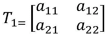
are the corrected image pixel coordinates. Transformation matrix
Can be split into four parts including:
which represents a linear transformation of the image,
for producing a perspective transformation of the image, T
3=[a
31 a
32]Representing image translation. At this time, the expression of the perspective transformation can be written as the following formula:
at this time, the known four original image pixel coordinates before correction can be substituted into the expression, so as to obtain the transformation formula. And then converting each pixel point in the first image into a new pixel point through a transformation formula to obtain a target image.
The embodiment of the invention provides an image conversion method, wherein terminal equipment can project light shadow on a learning page to be shot and acquire an image comprising the light shadow, a pixel point with the maximum brightness value in the light shadow is determined as a brightness value center of gravity point, an optical axis can be obtained at the moment, a camera of the terminal equipment and the learning page to be shot are not parallel, so that a certain included angle is formed between the optical axis and the acquired image, the image is deformed, and finally the acquired image is projected onto a vertical plane of the optical axis through a perspective transformation technology, and the image and the optical axis can be ensured to be completely vertical at the moment, so that the image which is not deformed after correction can be obtained. Therefore, the content required by the user can be identified in a targeted manner, and the accuracy of image identification and character identification can be improved.
Optionally, in a case where a visualization straight line exists in the shadow, after acquiring the first image including the shadow, the method may further include: and acquiring coordinates of two end points of the visualized straight line and coordinates of a middle point of the straight line. And respectively calculating a first slope of a straight line where the first end point and the middle point are located and a second slope of a straight line where the second end point and the middle point are located, and outputting a prompt message when the difference value between the first slope and the second slope is greater than a preset difference value, wherein the prompt message is used for prompting a user that the learning page to be shot is uneven.
The presence of a visual straight line in the light shadow means that a straight line exists in the outline of the light shadow, for example, the light shadow is a square or a rectangle, and the outline thereof is a straight line side; or the light shadow is in a cross shape and consists of two straight lines. When a visual straight line exists in the light shadow, if the learning page to be shot is placed flatly, the light shadow presented on the learning page to be shot also has a straight line; however, if the learning page to be photographed is not flat, for example, an arched book page is rolled up, the outline of the light and shadow presented on the learning page to be photographed changes, and the original straight line becomes a curve after being projected.
Illustratively, assuming the shadow is in the shape of a cross, the predetermined difference is based on the projection of the shadowThe accuracy of the device and the current shooting actual environment condition are comprehensively set, and the preset difference value is assumed to be 0.2. When the light projector projects the cross-shaped light on the learning page to be shot, three points on one edge, namely a left end point A, a cross point O and a right end point B, are taken. After the coordinate axes are established, the coordinates of three points are obtained: a (5, 2), O (6, 5), B (7, 6). At this time, the slope, k, of AO and BO is calculatedAO=(5-2)/(6-5)=3,kBO1 for (6-5)/(7-6), the difference between the two slopes is kAO-kBOIf the difference is greater than 2 and greater than the preset difference, it can be said that the learning page to be photographed is not flat. And at the moment, the terminal equipment outputs a prompt message which is used for advising the user to put the learning page flat.
According to the selectable technical scheme, the shape of the visual straight line in the light and shadow presented on the learning page to be shot is calculated, if the visual straight line presented on the learning page to be shot is not a straight line, the fact that the learning page to be shot is not flat can be shown, and then corresponding reminding is output. According to the technical scheme, the situation that the acquired images cannot be identified and the like due to the fact that the learning page is not flat can be avoided, and the power consumption of the terminal equipment is saved.
Example two
As shown in fig. 2, the image conversion method provided in the embodiment of the present invention may further include the following steps:
201. a first image and a second image are acquired.
The first image includes the light projected by the light projector, and the second image does not include the light projected by the light projector.
The terminal device may collect an image including the light after the light projector projects the light, and then turn off the light projector and collect an image not including the light within a preset time period, where the preset time period is set by the terminal device, and is generally a relatively small value, such as 0.1s, 0.2 s.
202. And acquiring the RGB value of each pixel point in the first image and the RGB value of each pixel point in the second image.
And the terminal equipment analyzes the first image and the second image respectively to obtain the RGB value of each pixel point in the two images.
It can be understood that there are i pixel points in the first image, respectively marked as X1、X2…Xi(ii) a There are also i pixel points in the second image, marked as Y respectively1、Y2…Yi. Each pixel has an RGB value.
203. And performing difference analysis on the RGB values of each corresponding pixel point in the first image and the second image.
In the embodiment of the invention, the terminal equipment processes the two images through image subtraction, and respectively subtracts the RGB values of the corresponding pixel points in the two images to obtain the difference value of the GRB value of each pixel point.
It can be understood that there are i pixel points in the first image, respectively marked as X1、X2…Xi(ii) a There are also i pixel points in the second image, marked as Y respectively1、Y2…Yi. Subtracting pixel points in the first image and the second image to obtain X1、X2…XiAnd Y1、Y2…YiAnd the two groups correspond to each other one by one according to the arrangement sequence. Mixing X1RGB value of minus Y1RGB value of (1), X2RGB value of minus Y2The RGB value of (1), and so on, XiRGB value of minus YiThe RGB value of (a). From this i RGB values of the difference can be obtained.
204. And determining the light shadow according to the pixel points of which the difference values of all the RGB values in the first image are greater than the preset value.
And comparing the obtained difference value of the i RGB values with a preset value, wherein all pixel points larger than the preset value are pixel points forming light shadow.
Illustratively, the preset value is set by the terminal device according to the brightness value of the light shadow transmitted by the light shadow projector, and is assumed to be 50. After performing difference analysis on the RGB values of each pixel point corresponding to the first image and the second image, if the difference between the RGB values of 20 pixel points among the i RGB values is greater than 50, it can be determined that the 20 pixel points form a shadow.
205. And calculating the RGB value of each pixel point in the shadow.
206. And determining the pixel point with the maximum RGB value as the center point of gravity of the brightness value of the shadow.
207. And determining an optical axis according to the light projector and the gravity center point of the brightness value.
208. And projecting the first image onto a vertical surface of an optical axis through a perspective transformation technology to obtain a target image.
In the embodiment of the present invention, for the description of steps 205 to 208, please refer to the detailed description of steps 102 to 105 in the first embodiment, which is not repeated herein.
The embodiment of the invention provides an image conversion method, which comprises the steps of acquiring an image with light shadow and an image without light shadow, carrying out difference analysis on pixel points in each image to obtain the light shadow, then determining a brightness value gravity center point and an optical axis, and projecting the acquired image onto a vertical plane of the optical axis through a perspective transformation technology. The technical scheme can obtain accurate light and shadow, can ensure that the image is completely vertical to the optical axis, obtains an image without deformation, and improves the accuracy of image recognition and character recognition.
As an optional implementation manner, before the first image including the light and shadow is acquired, an instruction sent by a user may be further received, where the instruction is used to trigger the terminal device to control the camera to acquire the image, and the instruction may be implemented in various forms, such as a click operation of a virtual control or a physical button in the terminal device by the user, or a voice instruction related to photographing input by the user.
The terminal equipment controls the camera to collect images and comprises a light projector and a learning page to be shot.
Furthermore, the terminal device responds to the first instruction of the user, the motion track of the finger of the user can be recorded through the camera, and if the terminal device detects that the finger of the user stays in a certain area in the learning page all the time within the preset time, the camera is controlled to adjust the shooting angle, so that the light projector can project light and shadow to the area where the finger is located in the learning page to be shot, and the camera is controlled to collect images.
For example, the preset duration may be a duration set by the terminal device, or may be set by the user, assuming that the preset duration is 8 s. If the terminal device detects that the user points at 8s with the finger, the triangular pyramid volume formula in the learning page is' V-1/3 pi r2h (the triangular pyramid volume is equal to the base area multiplied by the height divided by three, and the base area is equal to pi multiplied by the square of the radius) ", then the terminal device can control the camera to adjust the shooting angle, so that the light projector can project light to the area where the triangular pyramid volume formula in the learning page to be shot is located, and control the camera to acquire the image of the area where the triangular pyramid volume formula is located.
The user is likely to encounter difficulty in learning if the finger stays in a certain area for a long time. According to the implementation mode, when the duration of touch operation of a user is longer than the preset duration, the light projector is controlled to project light at the area where the fingers of the user are located and collect images, so that the user is helped to solve the problems encountered in the learning process.
EXAMPLE III
As shown in fig. 3, the image conversion method provided in the embodiment of the present invention may further include the following steps:
301. a first image including light and shadow is acquired.
302. And calculating the RGB value of each pixel point in the shadow.
303. And determining the pixel point with the maximum RGB value as the center point of gravity of the brightness value of the shadow.
304. And determining an optical axis according to the light projector and the gravity center point of the brightness value.
In the embodiment of the present invention, for the description of steps 301 to 304, please refer to the detailed description of steps 101 to 104 in the first embodiment, which is not repeated herein.
305. And determining the vertical plane of the optical axis by the target pixel points.
The target pixel point is any pixel point in the first image.
It should be noted that, determining the vertical plane requires establishing a three-dimensional space coordinate system. And taking any one pixel point as the origin of coordinates, and establishing a three-dimensional rectangular coordinate system to obtain the coordinate value of the target pixel point and the equation of the straight line where the optical axis is located. At the moment, a vertical line from the target pixel point to the optical axis is made, the intersection point of the vertical line and the straight line where the optical axis is located can be obtained, and another straight line which is perpendicular to the straight line where the optical axis is located and is not parallel to the vertical line from the target pixel point to the optical axis is made through the intersection point. At this time, the plane on which the two straight lines perpendicular to the straight line on which the optical axis is located and intersecting with each other in a non-parallel manner are located can be determined as the vertical plane of the optical axis.
306. And projecting all pixel points in the first image onto a vertical surface of the optical axis to obtain projected pixel points.
In the embodiment of the invention, after the vertical plane of the optical axis is obtained, all pixel points in the first image can be projected onto the vertical plane to obtain the coordinates of the projected new pixel points.
Optionally, projecting all pixel points in the first image onto a vertical plane of the optical axis specifically includes: establishing a circumscribed rectangle of the light shadow to obtain N tangent points of the light shadow and the circumscribed rectangle, wherein N is an integer greater than or equal to 4; establishing a coordinate axis through a target pixel point, and acquiring first coordinate values of N tangent points; substituting the first coordinate values of the N tangent points into a perspective change expression, and calculating to obtain a first perspective transformation matrix; and multiplying the first coordinate values of all the pixel points in the first image by the first perspective transformation matrix to obtain second coordinate values of all the pixel points.
It should be noted that, all the pixel points in the first image are projected onto the vertical plane of the optical axis, specifically, a perspective transformation matrix is determined by at least four tangent points in the first image, and then the whole first image is transformed according to the perspective transformation matrix. If the shadow rendered on the learning page is elliptical, then the elliptical shadow has four points of tangency with the circumscribed rectangle. Establishing coordinate axis through one of the tangent points to obtain coordinate A of the four tangent points1(u0,v0),A2(u1,v1),A3(u2,v2),A4(u3,v3). Substituting the coordinates of the four points into a perspective change expression
In (1). It should be noted that the transformation formula may be applied to a two-dimensional plane or a three-dimensional space, and in the embodiment of the present invention, the transformation formula is a two-dimensional plane transformation in the three-dimensional space. Wherein (u, v) is the pixel coordinate of the original image before correction, w can be used as a fixed parameter and does not participate in calculation,
are the corrected image pixel coordinates. Can be combined with
33When the coordinates of the four tangent points are taken into account, which is determined to be 1, the following equation can be obtained: a is
11x+a
12y+a
13-a
31xX-a
32yX=X,a
21x+a
22y+a
23-a
31xY-a
32Y ═ Y, where,
the coordinate of four tangent points is brought into the transformation matrix, and the perspective transformation matrix can be calculated
At this time, the coordinate of each pixel point in the first image is multiplied by the perspective transformation matrix A, so that a converted second coordinate value is obtained.
According to the optional technical scheme, at least four tangent points are obtained by establishing a circumscribed rectangle of a light shadow, then a perspective transformation matrix is obtained by calculation according to the four tangent points for image conversion, at the moment, the image and the optical axis can be ensured to be completely vertical, and an image which is not deformed after correction can be obtained. This can improve the accuracy of image recognition and character recognition.
307. And determining a third image according to the projected pixel points and the target pixel points.
And according to the obtained second coordinate value of each pixel point after conversion, combining the target pixel point to obtain a third image formed by all the pixel points.
308. And smoothing all pixel points in the third image to obtain a target image.
In the embodiment of the present invention, the terminal device usually performs smoothing processing on the third image by using a low-pass filtering method, so as to achieve the purpose of eliminating noise, and obtain the target image.
In the process of generating and transmitting the image signal, various noises interfere with the image signal, so that the obtained image is a noisy image, and generally, the image needs to be smoothed before being segmented and extracted. Generally, the image smoothing process is mainly to eliminate noise, and the noise is not limited to distortion and deformation visible to human eyes, and some noise can be found only when the image processing is performed. The common noise of the image is mainly additive noise, multiplicative noise, quantization noise and the like. Since the energy of the image is mainly concentrated in the low frequency part and the frequency band of the noise is mainly in the high frequency band, the noise is usually eliminated by adopting a low-pass filtering method. Common filtering includes mean filtering, median filtering, gaussian filtering, and the like.
The embodiment of the invention provides an image conversion method, wherein terminal equipment can project a light shadow on a learning page to be shot and collect an image comprising the light shadow, determine a pixel point with the maximum brightness value in the light shadow as a brightness value gravity center point, obtain an optical axis at the moment, project a first image on a vertical plane of the optical axis, and perform smoothing processing on the projected pixel point to obtain a final target image. The technical scheme can ensure that the image and the optical axis are completely vertical to obtain an image without deformation, and improves the accuracy of image recognition and character recognition.
As an optional implementation manner, after obtaining the target image, the terminal device displays the target image in a display screen of the terminal device, and the terminal device may further identify content in the target image, search the identification result in a pre-stored database, and display the obtained search result in a place other than the target image in the display screen of the terminal device.
Further, a first control may be displayed in a display screen of the terminal device, and the terminal device switches from displaying the target image and the search result to displaying the target image in response to a touch input to the first control by the user. The terminal device can also respond to the touch input of the user to the first control again, and switch from displaying the target image to displaying the target image and the search result.
In this optional implementation manner, the terminal device may set a control in the display page, display the search result in the display screen after searching for the target image, and if the user clicks the control, display the target image without the search result, that is, hide the search result. If the user clicks the control again, the search results will be displayed again. The technical scheme can search the target image and hide the target image when a search result is not needed, and different requirements of users can be met.
Example four
As shown in fig. 4, an embodiment of the present invention provides a terminal device, where the terminal device includes:
an acquisition module 401 is configured to acquire a first image including light and shadow.
A processing module 402, configured to calculate an RGB value of each pixel point in the shadow; and the first image is projected to a vertical surface of the optical axis through a perspective transformation technology to obtain a target image.
A determining module 403, configured to determine that a pixel point with the largest RGB value is a brightness value gravity center point of a light shadow; and determining an optical axis according to the light projector and the gravity center point of the brightness value.
Optionally, the obtaining module 401 is further configured to acquire a first image and a second image, where the second image does not include light and shadow; the RGB value of each pixel point in the first image and the RGB value of each pixel point in the second image are obtained;
the processing module 402 is further configured to perform difference analysis on RGB values of each pixel point in the first image and the second image;
the determining module 403 is further configured to determine a light shadow according to the pixel points in the first image where the difference between all RGB values is greater than the preset value.
Optionally, the determining module 403 is further configured to determine a vertical plane of the optical axis through the target pixel point, where the target pixel point is any one pixel point in the first image; and determining a third image according to the projected pixel points and the target pixel points.
The processing module 402 is further configured to project all pixel points in the first image onto a vertical plane of the optical axis to obtain projected pixel points; and the smoothing unit is used for smoothing all pixel points in the third image to obtain a target image.
Optionally, the processing module 402 is further configured to establish a circumscribed rectangle of the light shadow to obtain N tangent points of the light shadow and the circumscribed rectangle, where N is an integer greater than or equal to 4; the first coordinate axis is established through the target pixel point, the first coordinate values of the N tangent points are obtained, and the target pixel point is specifically any one of the N tangent points; the first coordinate values of the N tangent points are substituted into the perspective change expression, and a first perspective transformation matrix is obtained through calculation; and the second coordinate value of all the pixel points is obtained by multiplying the first coordinate values of all the pixel points in the first image by the first perspective transformation matrix.
Optionally, the obtaining module 401 is further configured to obtain a coordinate value of a first endpoint of the visual straight line, a coordinate value of a second endpoint of the visual straight line, and a coordinate value of a midpoint between the first endpoint and the second endpoint when the visual straight line exists in the shadow;
the processing module 402 is further configured to calculate a first slope of a straight line where the first end point and the middle point are located and a second slope of a straight line where the second end point and the middle point are located; and for calculating a difference between the first slope and the second slope;
the terminal equipment still includes:
an output module 404, configured to output a prompt message if the difference is greater than the preset difference, where the prompt message is used to prompt a user that a learning page to be photographed is uneven.
In the embodiment of the present invention, each module may implement the image conversion method provided in the above method embodiment, and may achieve the same technical effect, and in order to avoid repetition, the details are not repeated here.
As shown in fig. 5, an embodiment of the present invention further provides a terminal device, where the terminal device may include:
a memory 501 in which executable program code is stored;
a processor 502 coupled to a memory 501;
the processor 502 calls the executable program code stored in the memory 501 to execute the image conversion method executed by the terminal device in the above embodiments of the methods.
The terminal device according to the embodiment of the present invention may be a Mobile phone, a tablet Computer, a notebook Computer, a palm Computer, a vehicle-mounted terminal device, a wearable device, an Ultra-Mobile Personal Computer (UMPC), a netbook, or a Personal Digital Assistant (PDA). The wearable device may be a smart watch, a smart bracelet, a telephone watch, a smart foot ring, a smart earring, a smart necklace, a smart headset, or the like, and the embodiment of the present invention is not limited.
As shown in fig. 6, an embodiment of the present invention further provides a terminal device, where the terminal device includes, but is not limited to: a Radio Frequency (RF) circuit 601, a memory 602, an input unit 603, a display unit 604, a sensor 605, an audio circuit 606, a WiFi (wireless communication) module 607, a processor 608, a power supply 609, and a camera 610. Among other things, the radio frequency circuit 601 includes a receiver 6011 and a transmitter 6012. Those skilled in the art will appreciate that the terminal device configuration shown in fig. 6 does not constitute a limitation of the terminal device and may include more or fewer components than those shown, or some components may be combined, or a different arrangement of components.
The RF circuit 601 may be used for receiving and transmitting signals during information transmission and reception or during a call, and in particular, receives downlink information of a base station and then processes the received downlink information to the processor 608; in addition, the data for designing uplink is transmitted to the base station. In general, the RF circuit 601 includes, but is not limited to, an antenna, at least one amplifier, a transceiver, a coupler, a Low Noise Amplifier (LNA), a duplexer, and the like. In addition, the RF circuit 601 may also communicate with networks and other devices via wireless communications. The wireless communication may use any communication standard or protocol, including but not limited to global system for mobile communications (GSM), General Packet Radio Service (GPRS), Code Division Multiple Access (CDMA), Wideband Code Division Multiple Access (WCDMA), Long Term Evolution (LTE), email, Short Message Service (SMS), etc.
The memory 602 may be used to store software programs and modules, and the processor 608 executes various functional applications and data processing of the terminal device by operating the software programs and modules stored in the memory 602. The memory 602 may mainly include a program storage area and a data storage area, wherein the program storage area may store an operating system, an application program required by at least one function (such as a sound playing function, an image playing function, etc.), and the like; the storage data area may store data (such as audio data, a phonebook, etc.) created according to the use of the terminal device, and the like. Further, the memory 602 may include high speed random access memory, and may also include non-volatile memory, such as at least one magnetic disk storage device, flash memory device, or other volatile solid state storage device.
The input unit 603 can be used to receive input numeric or character information and generate key signal inputs related to user settings and function control of the terminal device. Specifically, the input unit 603 may include a touch panel 6031 and other input devices 6032. The touch panel 6031, also referred to as a touch screen, may collect touch operations of a user on or near the touch panel 6031 (e.g., operations of a user on or near the touch panel 6031 using any suitable object or accessory such as a finger, a stylus, etc.) and drive corresponding connection devices according to a preset program. Alternatively, the touch panel 6031 may include two parts of a touch detection device and a touch controller. The touch detection device detects the touch direction of a user, detects a signal brought by touch operation and transmits the signal to the touch controller; the touch controller receives touch information from the touch sensing device, converts the touch information into touch point coordinates, sends the touch point coordinates to the processor 608, and can receive and execute commands sent by the processor 608. In addition, the touch panel 6031 can be implemented by using various types of materials such as a resistive type, a capacitive type, an infrared ray, and a surface acoustic wave. The input unit 603 may include other input devices 6032 in addition to the touch panel 6031. In particular, other input devices 6032 may include, but are not limited to, one or more of a physical keyboard, function keys (such as volume control keys, switch keys, etc.), a trackball, a mouse, a joystick, and the like.
The display unit 604 may be used to display information input by the user or information provided to the user and various menus of the terminal device. The display unit 604 may include a display panel 6041, and the display panel 6041 may be configured in the form of a Liquid Crystal Display (LCD), an organic light-Emitting diode (OLED), or the like. Further, the touch panel 6031 can cover the display panel 6041, and when the touch panel 6031 detects a touch operation on or near the touch panel 6031, the touch operation is transmitted to the processor 608 to determine a touch event, and then the processor 608 provides a corresponding visual output on the display panel 6041 according to the touch event. Although in fig. 6, the touch panel 6031 and the display panel 6041 are two separate components to implement the input and output functions of the terminal device, in some embodiments, the touch panel 6031 and the display panel 6041 may be integrated to implement the input and output functions of the terminal device.
The terminal device may also include at least one sensor 605, such as a light sensor, motion sensor, and other sensors. Specifically, the light sensor may include an ambient light sensor that can adjust the brightness of the display panel 6041 according to the brightness of ambient light, and a proximity sensor that can exit the display panel 6041 and/or backlight when the terminal device is moved to the ear. As one of the motion sensors, the accelerometer sensor can detect the magnitude of acceleration in each direction (generally, three axes), detect the magnitude and direction of gravity when stationary, and can be used for applications (such as horizontal and vertical screen switching, related games, magnetometer attitude calibration) for recognizing the attitude of the terminal device, and related functions (such as pedometer and tapping) for vibration recognition; as for other sensors such as a gyroscope, a barometer, a hygrometer, a thermometer, and an infrared sensor, which can be configured in the terminal device, detailed description is omitted here. In the embodiment of the present invention, the terminal device may include an acceleration sensor, a depth sensor, a distance sensor, or the like.
Audio circuitry 606, speaker 6061, and microphone 6062 may provide an audio interface between the user and the terminal device. The audio circuit 606 may transmit the electrical signal converted from the received audio data to the speaker 6061, and convert the electrical signal into a sound signal by the speaker 6061 and output the sound signal; on the other hand, the microphone 6062 converts a collected sound signal into an electric signal, receives the electric signal by the audio circuit 606, converts the electric signal into audio data, processes the audio data by the audio data output processor 608, and sends the audio data to, for example, another terminal device via the RF circuit 601 or outputs the audio data to the memory 602 for further processing.
WiFi belongs to short distance wireless transmission technology, and the terminal device can help the user send and receive e-mail, browse web page and access streaming media etc. through WiFi module 607, it provides wireless broadband internet access for the user. Although fig. 6 shows the WiFi module 607, it is understood that it does not belong to the essential constitution of the terminal device, and may be omitted entirely as needed within the scope not changing the essence of the invention.
The processor 608 is a control center of the terminal device, connects various parts of the entire terminal device by various interfaces and lines, and performs various functions of the terminal device and processes data by running or executing software programs and/or modules stored in the memory 602 and calling data stored in the memory 602, thereby performing overall monitoring of the terminal device. Alternatively, processor 608 may include one or more processing units; preferably, the processor 608 may integrate an application processor, which primarily handles operating systems, user interfaces, applications, etc., and a modem processor, which primarily handles wireless communications. It will be appreciated that the modem processor described above may not be integrated into the processor 608.
The terminal device also includes a power supply 609 (e.g., a battery) for powering the various components, which may preferably be logically coupled to the processor 608 via a power management system, such that the power management system may be used to manage charging, discharging, and power consumption. Although not shown, the terminal device may further include a bluetooth module or the like, which is not described in detail herein.
In an embodiment of the present invention, the processor 608 is configured to acquire a first image including light and shadow;
calculating the RGB value of each pixel point in the shadow, and determining the pixel point with the maximum RGB value as the brightness value gravity center point of the shadow;
determining an optical axis according to the light projector and the gravity center point of the brightness value;
and projecting the first image onto a vertical surface of an optical axis through a perspective transformation technology to obtain a target image.
Optionally, the processor 608 may also be configured to implement other processes implemented by the terminal device in the foregoing method embodiments.
Embodiments of the present invention provide a computer-readable storage medium storing a computer program, wherein the computer program causes a computer to execute some or all of the steps of the method as in the above method embodiments.
Embodiments of the present invention also provide a computer program product, wherein the computer program product, when run on a computer, causes the computer to perform some or all of the steps of the method as in the above method embodiments.
Embodiments of the present invention further provide an application publishing platform, where the application publishing platform is configured to publish a computer program product, where the computer program product, when running on a computer, causes the computer to perform some or all of the steps of the method in the above method embodiments.
It should be appreciated that reference throughout this specification to "one embodiment" or "an embodiment" means that a particular feature, structure or characteristic described in connection with the embodiment is included in at least one embodiment of the present invention. Thus, the appearances of the phrases "in one embodiment" or "in an embodiment" in various places throughout this specification are not necessarily all referring to the same embodiment. Furthermore, the particular features, structures, or characteristics may be combined in any suitable manner in one or more embodiments. Those skilled in the art should also appreciate that the embodiments described in this specification are exemplary and alternative embodiments, and that the acts and modules illustrated are not required in order to practice the invention.
The terminal device provided by the embodiment of the present invention can implement each process shown in the above method embodiments, and is not described herein again to avoid repetition.
In various embodiments of the present invention, it should be understood that the sequence numbers of the above-mentioned processes do not imply an inevitable order of execution, and the execution order of the processes should be determined by their functions and inherent logic, and should not constitute any limitation on the implementation process of the embodiments of the present invention.
The units described as separate parts may or may not be physically separate, and parts displayed as units may or may not be physical units, may be located in one place, or may be distributed on a plurality of network units. Some or all of the units can be selected according to actual needs to achieve the purpose of the solution of the embodiment.
In addition, functional units in the embodiments of the present invention may be integrated into one processing unit, or each unit may exist alone physically, or two or more units are integrated into one unit. The integrated unit can be realized in a form of hardware, and can also be realized in a form of a software functional unit.
The integrated units, if implemented as software functional units and sold or used as a stand-alone product, may be stored in a computer accessible memory. Based on such understanding, the technical solution of the present invention, which is a part of or contributes to the prior art in essence, or all or part of the technical solution, can be embodied in the form of a software product, which is stored in a memory and includes several requests for causing a computer device (which may be a personal computer, a server, a network device, or the like, and may specifically be a processor in the computer device) to execute part or all of the steps of the above-described method of each embodiment of the present invention.
It will be understood by those skilled in the art that all or part of the steps in the methods of the embodiments described above may be implemented by hardware instructions of a program, and the program may be stored in a computer-readable storage medium, where the storage medium includes Read-Only Memory (ROM), Random Access Memory (RAM), Programmable Read-Only Memory (PROM), Erasable Programmable Read-Only Memory (EPROM), One-time Programmable Read-Only Memory (OTPROM), Electrically Erasable Programmable Read-Only Memory (EEPROM), Compact Disc Read-Only Memory (CD-ROM), or other Memory, such as a magnetic disk, or a combination thereof, A tape memory, or any other medium readable by a computer that can be used to carry or store data.