Background
The composite parts are widely applied to the aerospace field by the performances of high strength, high modulus, high temperature resistance, fatigue resistance and the like, and a large number of composite material structures are successfully adopted from military airplanes to civil airplanes. Wings, which are the main load bearing components, require higher strength and stiffness to meet performance and safety requirements during flight.
Currently, composite wings are typically manufactured by forming the components separately and then assembling them. The method adopts gluing and riveting in the assembly process, has complex working procedures, long manufacturing time and huge workload consumption, and directly leads to high production cost.
Disclosure of Invention
Technical problem to be solved
The invention aims to provide an integrated forming and assembling die and a forming and assembling method for multiple parts of a composite material wing, which are used for realizing integrated forming and assembling of the multiple parts of the composite material wing, shortening the manufacturing and assembling time, simplifying the working procedures, saving the cost and reducing the production cost.
(II) technical scheme
In order to achieve the above object, in a first aspect, the invention provides an assembly mold for integrally molding multiple parts of a composite material wing,
the method comprises the following steps:
the forming side of the first side die is provided with a first cavity matched with a first side skin of the composite material wing;
the joint positioning block is detachably arranged on the forming side of the first side die and positioned outside one end of the first cavity, and bayonets matched with the number and positions of the girders of the composite material wing are arranged on the joint positioning block and used for fixing one end of the corresponding girder;
the root rib positioning blocks are arranged on the molding side of the first side mold and located between the first cavity and the joint positioning blocks, the root rib positioning blocks are arranged at intervals in sections, the interval between every two adjacent sections of the root rib positioning blocks is used for penetrating through corresponding main beams, and each section of the root rib positioning block corresponds to one section of the root rib molding core mold;
the end rib positioning block is arranged on the forming side of the first side die and positioned on the outer side of the other end of the first cavity, and an end rib forming core die is arranged between the end rib positioning block and the first cavity;
the second side die is characterized in that a second cavity matched with a second side skin of the composite wing is formed in the forming side of the second side die, the second side die is buckled with the first side die, the first cavity and the second cavity form a wing cavity, a plurality of inner profile core dies are arranged in the wing cavity and arranged at intervals, the interval between every two adjacent inner profile core dies is used for penetrating through corresponding main beams, and the profiles on the two sides of the inner profile core dies are respectively matched with the inner side profiles of the first side skin and the second side skin.
Preferably, the end rib core mold comprises a metal part and a silicon rubber part, and the silicon rubber part covers the outer side of the metal part.
Preferably, the inner profile core die is a PMI foam.
Preferably, the rib core mold is made of PMI foam or silicone rubber.
Preferably, the first side die and the second side die are metal dies.
Preferably, the joint positioning block is fixed on the first side die through a screw; and/or
The end rib positioning block is fixed on the first side die through a screw.
Preferably, an aileron interface limiting block is arranged at an aileron interface of the composite material wing, and the aileron interface limiting block fixes the first side mold through a screw
In a second aspect, the invention further provides a method for integrally forming and assembling multiple parts of a composite material wing, which is performed by using the composite material wing multiple part integrally forming and assembling mold of any one of the first aspect,
the method comprises the following steps:
firstly, respectively paving a first side wing skin and a second side wing skin in a first cavity and a second cavity;
secondly, C-shaped end rib skins are paved on the end rib forming core mold, and C-shaped root rib skins are paved on each section of root rib forming core mold respectively;
thirdly, placing the prefabricated girder and the inner profile core mold on a first side wing skin, placing the end rib core mold paved with the end rib skin and the root rib core mold paved with the root rib skin at corresponding positions, and placing the prefabricated girder, the inner profile core mold, the end rib core mold paved with the end rib skin and the root rib core mold paved with the root rib skin at preset positions;
step four, accurate positioning; positioning one end of the main beam on the first side mold by using a joint positioning block, positioning a root rib core mold paved with a root rib skin by using a root rib positioning block, and paving an end rib core mold after the end rib skin by using an end rib positioning block;
step five, buckling a second side mold paved on a second side wing skin on the first side mold, pressurizing, heating, curing and molding;
and step six, demolding, namely detaching the joint positioning block, the root rib positioning block, the end rib positioning block, the root rib core mold and the end rib core mold to obtain the composite material wing assembled into a whole.
Preferably, when the thickness of the wing skin is 1mm to 3mm, the PMI foam is adopted for the inner profile core die.
Preferably, when the thickness of the root rib skin is 1 mm-3 mm, the PMI foam is adopted for the root rib core mold, and when the thickness of the root rib skin is more than 3mm, the silicone rubber is adopted for the root rib core mold; and/or
When the thickness of the end rib skin is 1 mm-3 mm, the PMI foam is adopted as the end rib core mold, and when the thickness of the end rib skin is more than 3mm, the silicon rubber is adopted as the end rib core mold.
(III) advantageous effects
The technical scheme of the invention has the following advantages: the invention provides an integrated forming and assembling die for multiple parts of a composite wing, which is characterized in that a first side skin and a second side skin are respectively paved in a first cavity and a second cavity, a prefabricated main beam and an inner profile core die are arranged on the first side skin, skins are respectively paved on a root rib core die and an end rib core die, a joint positioning block is used for positioning the main beam, the root rib core die and the end rib core die which are paved with the skins are respectively positioned by the root rib positioning block and the end rib positioning block, the second side die is buckled on the first side die after the positioning is finished, the integral pressing and heating curing forming are carried out, and after the demoulding, the root rib core die and the end rib core die are removed, so that the assembled composite wing can be obtained. The mould can integrally form the first side skin, the second side skin, the root rib and the end rib, and the integral assembly of the composite material wing is completed after the mould is formed, so that the manufacturing and assembling time is shortened, the working procedures are simplified, the cost is saved, and the production cost is reduced.
The multi-part integrated forming and assembling method for the composite material wing provided by the invention realizes the multi-part integrated forming of the composite material wing and the integrated assembling of the composite material wing by using a set of forming die, shortens the manufacturing and assembling time, simplifies the working procedures, saves the cost and reduces the production cost.
Detailed Description
In order to make the objects, technical solutions and advantages of the embodiments of the present invention clearer, the technical solutions in the embodiments of the present invention will be clearly and completely described below with reference to the drawings in the embodiments of the present invention, and it is obvious that the described embodiments are some, but not all, embodiments of the present invention. All other embodiments, which can be obtained by a person skilled in the art without any inventive step based on the embodiments of the present invention, are within the scope of the present invention.
Example one
Referring to fig. 3, 6 and 7, a composite wing 600 has a wing length of 2.1m, and the prepreg selected for the skin is a carbon fiber/epoxy resin prepreg. The composite wing 600 comprises a first side skin 601, a second side skin 602, two girders 603, an inner profile core die 604 positioned between the first side skin 601 and the second side skin 602, a root rib 605 positioned at the root end of the composite wing 600, and an end rib 606 positioned at the end part of the composite wing 600, wherein the two girders 602 are arranged at intervals, the inner profile core die 604 is positioned between the first side skin 601 and the second side skin 602 and is divided into three parts by the two girders 603, and the inner profile core die 604 and the two girders 603 form an upper surface and a lower surface which are respectively matched with the inner side surfaces of the first side skin 601 and the second side skin 602.
Referring to fig. 6, a root rib 605 is located at the root end of the composite wing 600, divided into three sections by two main beams 603 and secured to the two main beams 603 and the inner profile core 604 at that end.
Referring to fig. 7, an end rib 606 is located at the other end of the composite wing 600 far from the root end, the end rib 606 is fixed with two main girders 603 and an inner profile core mold 604 of the end, and an aileron interface 607 is arranged at the corresponding position of the composite wing 600.
Both the root rib 605 and the end rib 606 are made of composite material.
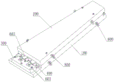
Referring to fig. 1 to 5, the multi-part integrally molding assembly mold for a composite wing according to the embodiment of the present invention realizes the multi-part integrally molding of the composite wing and the integrally assembling of the composite wing at the same time, and the multi-part integrally molding assembly mold for a composite wing includes a first side mold 100, a second side mold 200, a joint positioning block 300, a root rib positioning block 400, and an end rib positioning block 500.
The forming side of the first side die 100 is provided with a first cavity matched with a first side skin of the composite material wing, and the forming side of the second side die 200 is provided with a second cavity matched with a second side skin of the composite material wing.
Referring to fig. 1, 3 and 5, the joint positioning block 300 is detachably mounted on the forming side of the first side die 100 and located outside one end of the first cavity, a bayonet matched with the number and position of the main beams 603 is provided on the joint positioning block 3, for example, the composite wing 600 has three main beams 603 arranged at intervals, and three bayonets with the same interval distance as the main beams 603 are provided on the joint positioning block 3 and are respectively used for fixing one ends of the three main beams 603. It should be noted that the number of the main beams 603 may be adjusted in the interval (relative position) as needed.
Referring to fig. 1, 3 and 5, the rib positioning block 400 is disposed on the molding side of the first side mold 100 and located between the first cavity and the joint positioning block 300, the rib positioning block 400 is disposed at intervals in sections, an interval between every two adjacent sections of the rib positioning block 400 is used to pass through the corresponding main beam 603, and each section of the rib positioning block 400 corresponds to a section of the rib molding core mold.
Referring to fig. 2 and 5, an end rib positioning block 500 is disposed at a molding side of the first side mold and outside the other end of the first cavity, and an end rib molding core mold is disposed between the end rib positioning block 500 and the first cavity.
Referring to fig. 4, when the second side mold 200 is engaged with the first side mold 100, the first cavity and the second cavity form an airfoil cavity, a plurality of inner profile core molds 604 are disposed in the airfoil cavity, the plurality of inner profile core molds 604 are disposed at intervals, an interval between every two adjacent inner profile core molds 604 is used for passing through a corresponding main beam 603, and two side profiles of the plurality of inner profile core molds 604 are respectively matched with the inner side profiles of the first side skin 601 and the second side skin 602.
When the composite material wing 600 is used, a first side skin 601 and a second side skin 602 are respectively paved in a first cavity and a second cavity, a prefabricated main beam 603 and an inner profile core 604 are arranged on the first side skin 601, skins are respectively paved on a root rib core mould and an end rib core mould, the main beam 603 is positioned by using a joint positioning block 300, the root rib core mould and the end rib core mould which are paved with the skins are respectively positioned by using a root rib positioning block 400 and an end rib positioning block 500, the second side mould 200 is buckled on the first side mould 100 after the positioning is finished, the integral pressurization and the heating curing molding are carried out, and after the demoulding, the root rib core mould and the end rib core mould are removed, so that the assembled composite material wing 600 can be obtained. The multi-part integrated forming assembly die for the composite wing can be used for integrally forming the first side skin 601, the second side skin 602, the root rib 605 and the end rib 606, and the integrated assembly of the composite wing 600 is completed after the forming, so that the manufacturing and assembly time is shortened, the working procedures are simplified, the cost is saved, and the production cost is reduced.
In some preferred embodiments, the end rib core mold comprises a metal part and a silicon rubber part, the silicon rubber part covers the outer side of the metal part, and the end rib is pressed and formed through expansion of silicon rubber, so that the end rib 606 can be well formed.
In some preferred embodiments, the inner-facing core mold 604 is a PMI foam.
In some preferred embodiments, the rib core is of PMI foam or silicone rubber.
In some preferred embodiments, the first side die and the second side die are metal dies.
In some preferred embodiments, the joint positioning block 300 is fixed to the first side mold 100 by screws, and preferably, the end rib positioning block 300 is fixed to the first side mold 100 by screws. The joint positioning block 300 and the joint positioning block 300 may be fixed to the first side mold 100 by screws, which facilitates disassembly and assembly, and may be accurately positioned.
In order to facilitate accurate forming of the aileron interface 607 and better uncured composite wing 600 before forming, in some preferred embodiments, an aileron interface stopper 700 is disposed at the aileron interface of the composite wing 600, the aileron interface stopper 700 fixes the first side mold 100 by a screw, and the shape of the aileron interface stopper 700 matches the shape of the aileron interface.
In order to facilitate the lifting of the forming mold, lifting rings 800 are provided at the side edges of the first side mold 100 and the second side mold 200.
In the present invention, the joint positioning block, the root rib positioning block, and the end rib positioning block may be block-shaped, L-shaped, or a combination of both, and of course, one positioning block may be a combination of a plurality of block-shaped, L-shaped, or different numbers of block-shaped and L-shaped plates. The whole or each part of the first side die may be fixed to the first side die by a screw, and the mounting surface having the positioning surface may be any mounting surface, which is not limited herein.
Example two
In the second embodiment, the method for integrally forming and assembling the multiple parts of the composite material wing provided in the first embodiment is directly used for forming and assembling by using any one of the multiple parts of the composite material wing integrally forming and assembling dies of the first embodiment, and includes the following steps:
step one, respectively paving a first side wing skin and a second side wing skin in a first cavity and a second cavity. Preferably, the method of vacuumizing and pre-compacting is adopted for pre-compacting, so that the first side wing skin and the second side wing skin are connected with the first cavity and the second cavity more firmly respectively, and the layers of pre-impregnated materials are attached to each other more.
And secondly, paving C-shaped end rib skins on the end rib forming core mold, and paving C-shaped root rib skins on each section of root rib forming core mold respectively. The opening of the C-shaped end rib skin faces outwards (the end far away from the root rib), so that the end rib core mold can be conveniently removed after molding. The opening of the C-shaped rib skin faces outwards (the side far away from the end rib), so that a rib core mold can be conveniently removed after molding. Preferably, the root rib skins and the end rib skins are pre-pressed by a vacuumizing and pre-pressing method, so that the layers of the prepreg are more attached to each other.
And thirdly, placing the prefabricated girder and the inner profile core mold on a first side wing skin, placing the end rib core mold paved with the end rib skin and the root rib core mold paved with the root rib skin at corresponding positions, and placing the prefabricated girder, the inner profile core mold, the end rib core mold paved with the end rib skin and the root rib core mold paved with the root rib skin at preset positions.
Step four, accurate positioning; and positioning one end of the main beam on the first side mold by using a joint positioning block, positioning a root rib core mold paved with a root rib skin by using a root rib positioning block, and paving an end rib core mold behind the end rib skin by using an end rib positioning block.
And step five, buckling the second side mold paved on the second side wing skin on the first side mold, pressurizing and heating the forming mold to solidify and form the composite wing.
And step six, demolding, namely detaching the joint positioning block, the root rib positioning block, the end rib positioning block, the root rib core mold and the end rib core mold to obtain the composite material wing assembled into a whole.
According to the forming and assembling method, the multi-part integral forming of the composite material wing and the integral assembling of the composite material wing are realized by using one set of forming die, the manufacturing and assembling time is shortened, the working procedures are simplified, the cost is saved, and the production cost is reduced.
More specifically, the forming and assembling method can save a plurality of sets of rib forming tools (particularly, the rib is related to the number of divided sections of the rib, three sets of rib forming tools are saved when the rib is divided into three sections), one set of end rib forming tool and two sets of wing skin forming tools, only one set of beam forming tool and the integrated forming and assembling die are needed, the equipment cost can be saved by more than 70%, the rib, the end rib and the upper and lower wing skins are synchronously formed while the composite material wing is formed, and the working hours can be saved by 70%; only one set of tool needs to be detected during detection, and the detection time of the tool can be saved by 70%.
In the embodiment, the main beam is used as a main bearing part and is molded in advance or formed by autoclave.
In some preferred embodiments, the inner core mold is made of a low-density material with certain rigidity, such as PMI foam, and especially when the thickness of the wing skin is 1mm to 3mm, the PMI foam is preferably used for the inner core mold. The PMI foam has certain rigidity and can serve as an inner profile core mold, the PMI foam is used as a supporting component of the composite material wing, the PMI foam does not need to be taken out during forming, meanwhile, the PMI foam is heated to a certain expansion amount, pressure can be applied to the skin from the inside, the skin is pressed more compactly, and the forming quality is higher.
In some preferred embodiments, the PMI foam is preferably used for the root rib core mold when the thickness of the root rib skin is 1mm to 3mm, and the silicone rubber is preferably used for the root rib core mold when the thickness of the root rib skin is 3mm or more.
In some preferred embodiments, the PMI foam is preferably used for the end rib core mold when the thickness of the end rib skin is 1mm to 3mm, and the silicone rubber is preferably used for the end rib core mold when the thickness of the end rib skin is 3mm or more.
When the forming die with the aileron interface limiting block is used, the aileron interface limiting block is firstly installed on the first side die before the first side skin is laid.
It should be noted that, the method of pre-pressing the first side skin, the second side skin, the root rib skin and the end rib skin by using the vacuum pumping pre-pressing method is the prior art, and is not described herein again.
It should be further noted that, the pressurization and heating of the forming mold, i.e., the curing and forming process of the composite material wing, such as pressure, temperature, pressurization and heating time, are all the prior art, and are not described herein again.
Finally, it should be noted that: the above examples are only intended to illustrate the technical solution of the present invention, but not to limit it; although the present invention has been described in detail with reference to the foregoing embodiments, it will be understood by those of ordinary skill in the art that: each embodiment does not include only one independent technical solution, and in the case of no conflict between the solutions, the technical features mentioned in the respective embodiments can be combined in any way to form other embodiments which can be understood by those skilled in the art.
Furthermore, modifications may be made to the technical solutions described in the foregoing embodiments, or equivalents may be substituted for some of the technical features thereof, without departing from the scope of the present invention, and the essence of the corresponding technical solutions does not depart from the spirit and scope of the technical solutions of the embodiments of the present invention.