CN112236058A - Playground equipment for children - Google Patents
Playground equipment for children Download PDFInfo
- Publication number
- CN112236058A CN112236058A CN201980029789.4A CN201980029789A CN112236058A CN 112236058 A CN112236058 A CN 112236058A CN 201980029789 A CN201980029789 A CN 201980029789A CN 112236058 A CN112236058 A CN 112236058A
- Authority
- CN
- China
- Prior art keywords
- frame
- dynamic hinge
- configuration
- dynamic
- children
- Prior art date
- Legal status (The legal status is an assumption and is not a legal conclusion. Google has not performed a legal analysis and makes no representation as to the accuracy of the status listed.)
- Pending
Links
Images


Classifications
-
- A—HUMAN NECESSITIES
- A47—FURNITURE; DOMESTIC ARTICLES OR APPLIANCES; COFFEE MILLS; SPICE MILLS; SUCTION CLEANERS IN GENERAL
- A47D—FURNITURE SPECIALLY ADAPTED FOR CHILDREN
- A47D13/00—Other nursery furniture
- A47D13/06—Children's play- pens
- A47D13/061—Children's play- pens foldable
- A47D13/063—Children's play- pens foldable with soft walls
-
- A—HUMAN NECESSITIES
- A01—AGRICULTURE; FORESTRY; ANIMAL HUSBANDRY; HUNTING; TRAPPING; FISHING
- A01K—ANIMAL HUSBANDRY; AVICULTURE; APICULTURE; PISCICULTURE; FISHING; REARING OR BREEDING ANIMALS, NOT OTHERWISE PROVIDED FOR; NEW BREEDS OF ANIMALS
- A01K1/00—Housing animals; Equipment therefor
- A01K1/0035—Transportable or mobile animal shelters
-
- A—HUMAN NECESSITIES
- A45—HAND OR TRAVELLING ARTICLES
- A45B—WALKING STICKS; UMBRELLAS; LADIES' OR LIKE FANS
- A45B19/00—Special folding or telescoping of umbrellas
-
- A—HUMAN NECESSITIES
- A45—HAND OR TRAVELLING ARTICLES
- A45B—WALKING STICKS; UMBRELLAS; LADIES' OR LIKE FANS
- A45B25/00—Details of umbrellas
- A45B25/10—Umbrella crowns
-
- A—HUMAN NECESSITIES
- A47—FURNITURE; DOMESTIC ARTICLES OR APPLIANCES; COFFEE MILLS; SPICE MILLS; SUCTION CLEANERS IN GENERAL
- A47D—FURNITURE SPECIALLY ADAPTED FOR CHILDREN
- A47D13/00—Other nursery furniture
- A47D13/06—Children's play- pens
- A47D13/061—Children's play- pens foldable
-
- A—HUMAN NECESSITIES
- A47—FURNITURE; DOMESTIC ARTICLES OR APPLIANCES; COFFEE MILLS; SPICE MILLS; SUCTION CLEANERS IN GENERAL
- A47D—FURNITURE SPECIALLY ADAPTED FOR CHILDREN
- A47D9/00—Cradles ; Bassinets
- A47D9/005—Cradles ; Bassinets foldable
-
- E—FIXED CONSTRUCTIONS
- E04—BUILDING
- E04B—GENERAL BUILDING CONSTRUCTIONS; WALLS, e.g. PARTITIONS; ROOFS; FLOORS; CEILINGS; INSULATION OR OTHER PROTECTION OF BUILDINGS
- E04B1/00—Constructions in general; Structures which are not restricted either to walls, e.g. partitions, or floors or ceilings or roofs
- E04B1/343—Structures characterised by movable, separable, or collapsible parts, e.g. for transport
- E04B1/344—Structures characterised by movable, separable, or collapsible parts, e.g. for transport with hinged parts
- E04B1/3441—Structures characterised by movable, separable, or collapsible parts, e.g. for transport with hinged parts with articulated bar-shaped elements
-
- E—FIXED CONSTRUCTIONS
- E04—BUILDING
- E04H—BUILDINGS OR LIKE STRUCTURES FOR PARTICULAR PURPOSES; SWIMMING OR SPLASH BATHS OR POOLS; MASTS; FENCING; TENTS OR CANOPIES, IN GENERAL
- E04H15/00—Tents or canopies, in general
- E04H15/32—Parts, components, construction details, accessories, interior equipment, specially adapted for tents, e.g. guy-line equipment, skirts, thresholds
- E04H15/34—Supporting means, e.g. frames
- E04H15/44—Supporting means, e.g. frames collapsible, e.g. breakdown type
- E04H15/48—Supporting means, e.g. frames collapsible, e.g. breakdown type foldable, i.e. having pivoted or hinged means
-
- F—MECHANICAL ENGINEERING; LIGHTING; HEATING; WEAPONS; BLASTING
- F16—ENGINEERING ELEMENTS AND UNITS; GENERAL MEASURES FOR PRODUCING AND MAINTAINING EFFECTIVE FUNCTIONING OF MACHINES OR INSTALLATIONS; THERMAL INSULATION IN GENERAL
- F16C—SHAFTS; FLEXIBLE SHAFTS; ELEMENTS OR CRANKSHAFT MECHANISMS; ROTARY BODIES OTHER THAN GEARING ELEMENTS; BEARINGS
- F16C11/00—Pivots; Pivotal connections
- F16C11/04—Pivotal connections
Landscapes
- Engineering & Computer Science (AREA)
- Architecture (AREA)
- Life Sciences & Earth Sciences (AREA)
- General Engineering & Computer Science (AREA)
- Environmental Sciences (AREA)
- Civil Engineering (AREA)
- Structural Engineering (AREA)
- Biodiversity & Conservation Biology (AREA)
- Animal Husbandry (AREA)
- Zoology (AREA)
- Mechanical Engineering (AREA)
- Physics & Mathematics (AREA)
- Electromagnetism (AREA)
- Pivots And Pivotal Connections (AREA)
- Toys (AREA)
Abstract
A playard device (10) for children, comprising: a support frame (30) comprising a plurality of frame elements, at least a portion of which are pivotally coupled to one another to enable the support frame to be folded from an unfolded configuration to a folded configuration; a flexible cover material supported by the support frame, the cover material configured to move with the support frame when the support frame is folded from an unfolded configuration to a folded configuration; at least one dynamic hinge (60, 62) coupled between at least two of the plurality of frame elements, the dynamic hinge allowing pivotal movement between the at least two frame elements and biasing the support frame from the folded configuration to the unfolded configuration.
Description
Cross Reference to Related Applications
This application claims the benefit of U.S. provisional patent application serial No. 62/665,842, filed on 2018, 5/2, the entire contents of which are hereby incorporated by reference herein for all purposes.
Technical Field
The present disclosure relates generally to the field of dynamic structural devices, and in example forms to accessories and support devices requiring setup and/or assembly, such as for children, infants, adults, and animals. The present disclosure also relates to foldable devices and accessories, such as children's accessories, that incorporate folding and self-assembling structures with dynamic hinge elements.
Disclosure of Invention
In example embodiments, the present disclosure is directed to dynamic hinges or joints that may be adapted for use with various devices, structures, systems, and/or methods. For example, a folding and self-assembling structural frame including one or more dynamic hinges may be incorporated into a child's playground, bassinet, pet house, container, umbrella, or various other devices. In an example form, two or more structural elements, such as frame members, are coupled together by a hinge or pivot joint that contains one or more resilient elements that bias the structural elements from a first configuration to a different second configuration. For example, the dynamic hinges of a collapsed playard may bias the playard frame from a compact collapsed configuration for storage and transport to an upright deployed configuration for use to provide a fully or partially self-assembled structure allowing parents or adult caregivers to more easily set up the playard.
In one aspect, the present disclosure is directed to a playard device for a child. The playard unit preferably includes a support frame having a plurality of frame elements, at least a portion of which are pivotally coupled to one another to enable the support frame to be folded from an unfolded configuration to a folded configuration. The playard unit preferably further comprises a flexible cover material supported by the support frame, the cover material being configured to move with the support frame when the support frame is folded from the expanded configuration to the folded configuration. The playard unit preferably further comprises at least one dynamic hinge coupled between at least two of the plurality of frame members, the dynamic hinge allowing pivotal movement between the at least two frame members and biasing the support frame from the collapsed configuration to the expanded configuration.
In another aspect, the present disclosure is directed to a dynamic hinge assembly for pivotally coupling first and second frame elements of a device. The dynamic hinge assembly preferably includes at least one resilient member having a first portion attached to the first frame element, a second portion attached to the second frame element, and an intermediate portion held in tension between the first and second portions to bias the first and second frame elements from a first configuration to a different second configuration.
In yet another aspect, the present disclosure is directed to a folding apparatus that includes a structural support frame having a first frame element, a second frame element, a third frame element, and a fourth frame element. The frame is preferably reconfigurable between an expanded configuration and a compact configuration. The folding device preferably further comprises a dynamic hinge pivotally coupling at least the first frame element and the second frame element. The dynamic hinge preferably comprises at least one resilient element which is engaged in tension between the first frame element and the second frame element when the frame is in its compact configuration. In this way, the elastic element at least partially assists in fitting the frame from the compact configuration to the expanded configuration.
The various aspects, features and advantages of the disclosure will be understood with reference to the drawings and detailed description herein, and will be realized by means of the various elements and combinations particularly pointed out in the appended claims. It is to be understood that both the foregoing general description and the following brief description of the drawings, and the detailed description of the exemplary embodiments, are intended to be illustrative of the exemplary embodiments of the invention claimed, and not restrictive.
Drawings
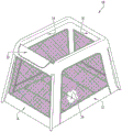
Fig. 1 is a perspective view of a playard device for a child incorporating a dynamic hinge according to an example embodiment of the present disclosure.
Fig. 2 is a perspective view of the frame of the child's playard apparatus shown in fig. 1 with the fabric or textile cover and wall panels removed, showing the dynamic hinge frame structure in its erected and deployed configurations.
Figures 3A-3D illustrate details of the dynamic hinge elements and the sequence of assembly of the playard frame shown in figure 2 that is transformed between a collapsed configuration and an upright and expanded configuration according to an example embodiment of the present disclosure.
Fig. 4A-4E illustrate a dynamic hinge element according to another example embodiment of the present disclosure.
Fig. 5A-5E illustrate a dynamic hinge element according to another example embodiment of the present disclosure.
Fig. 6A-6E illustrate a dynamic hinge element according to another example embodiment of the present disclosure.
Fig. 7A-7E illustrate a dynamic hinge element according to another example embodiment of the present disclosure.
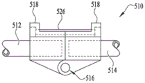
Fig. 8A-8D illustrate a dynamic hinge element according to another example embodiment of the present disclosure.
FIGS. 9A-9C illustrate a bassinet apparatus with foldable support legs and dynamic hinges according to example embodiments of the disclosure.
Figures 10A-10F illustrate a frame structure for a playard or other assembly having foldable support legs and dynamic hinges according to another example embodiment of the present disclosure.
11A-11E illustrate a self-assembled playard with dynamic hinges, according to another example embodiment of the present disclosure.
Fig. 12A and 12B illustrate a self-assembling frame structure for a playard or other assembly having a locking dynamic hinge according to another example embodiment of the present disclosure.
Fig. 13A-13G illustrate a locking dynamic hinge according to an example embodiment of the present disclosure.
Fig. 14A-14D illustrate a playard device for a child having a folding frame that incorporates dynamic hinges, according to another example embodiment of the present disclosure.
Fig. 15A and 15B illustrate additional embodiments of dynamic hinges according to other example embodiments of the present disclosure.
Figures 16A-16C illustrate details of a frame assembly with a locking dynamic hinge for a structure according to an example embodiment of the present disclosure.
17A-17C illustrate another example embodiment of a dynamic hinge.
FIG. 18 illustrates a folding pet house having a folding frame that incorporates dynamic hinges, according to another example embodiment of the present disclosure.
Fig. 19 shows a folding umbrella incorporating a dynamic hinge mechanism according to another example embodiment of the present disclosure.
Detailed Description
The present invention may be understood more readily by reference to the following detailed description of exemplary embodiments taken in conjunction with the accompanying drawings, which form a part of this disclosure. It is to be understood that this invention is not limited to the specific devices, methods, conditions or parameters described and/or illustrated herein, and that the terminology used herein is for the purpose of describing particular embodiments by way of example only and is not intended to be limiting of the claimed invention. Any and all patents and other publications identified in this specification are herein incorporated by reference as if fully set forth.
Also, as used in the specification including the appended claims, the singular forms "a," "an" (and the indefinite articles a and an) include the plural, and reference to a particular numerical value includes at least that particular value, unless the context clearly dictates otherwise. Ranges may be expressed herein as from "about" or "approximately" one particular value, and/or to "about" or "approximately" another particular value. When such a range is expressed, another embodiment includes from the one particular value and/or to the other particular value. Similarly, when values are expressed as approximations, by use of the antecedent "about," it will be understood that the particular value forms another embodiment.
Fig. 1-3 show a device in the form of a child's playard 10 including a frame structure 30 having dynamic hinge elements according to an example embodiment of the present disclosure. Playard 10 generally includes a fabric or textile, such as first and second side wall panels 12, 14 and first and second end wall panels 16, 18, mounted to a frame 30. The wall panel optionally includes a nylon or other fabric portion having a mesh or screen insert portion for visibility and airflow. Alternatively, the textile product may include a frame covering panel 22, the frame covering panel 22 covering the folding joints of the frame 30 to prevent contact with possible kinks. A floor 24, such as a multi-panel, collapsible infill floor, is optionally provided at the base or bottom of the playard 10. Playard 10 defines an interior volume in which a child may rest or play, bounded by wall panels and a floor panel, having a top opening for access to the volume. In an example embodiment, the frame structure of the apparatus includes a plurality of articulated joints and may be folded from an unfolded use configuration to a more compact folded configuration for storage and transport. One or more dynamic hinges with resilient deployment members may be provided to assist in assembly or deployment of the device, or to provide self-assembly or deployment of the device. The deployment frame operates to tension a textile component carried on the frame so as to define an interior receiving space. The dynamic hinge optionally locks the frame to the assembled configuration when the frame is fully deployed. Optionally providing one or more fasteners or closure mechanisms, e.g. straps, hooks and loops (Velcro)TM) Attaching material, snaps, zippers, buttons, etc. to hold the device in a folded state against the deployment bias of the dynamic hinge until the user releases the fastener or closure to deploy the device. In an exemplary embodiment, when the fastener or closure is released, the hinge is engagedThe tension on the resilient member is released and the outward or deployment bias of the dynamic hinge causes the frame to deploy substantially automatically. Alternatively, the deployment biasing force applied by the elastic members of the dynamic hinges may be selectively controlled to assist the user in deploying the frame to assemble the device.
Fig. 2 shows additional details of the frame structure 30 in its erected and unfolded use configuration, with the textile wall and floor panels removed for clarity. The frame 30 generally comprises a three-dimensional rectangular prism or frustum structure. The frame 30 includes four generally upright corner posts or leg members 32, 34, 36, 38; first and second upper side rails 42, 44; and first and second upper end rails 46, 48. The upper end rails 46, 48 each include first and second end rail segments 46A, 46B and 48A, 48B. Corner brackets 52, 54, 56, 58 couple the frame members at the upper corners of the frame structure 30. Each corner bracket 52, 54, 56, 58 is coupled with a respective one of the legs 32, 34, 36, 38, such as by engaging the upper end of the leg within the lower receiver portion of the bracket; engaging a respective one of the side rails 42, 44, such as by engaging an end of the side rail in a first lateral receiver portion of the bracket; and engages a respective one of the end rail segments 46A, 46B and 48A, 48B, such as by engaging the end of the end rail segment in the second lateral receiver portion of the bracket. The legs 32, 34, 36, 38 are pivotally or foldably coupled to their respective corner brackets 52, 54, 56, 58 by hinges or pin couplings, allowing the legs to be folded from an upright and unfolded use configuration shown in fig. 2 to a more compact folded storage and transport configuration shown in fig. 3A. The outer ends of the end rail segments 46A, 46B and 48A, 48B are also pivotally or foldably coupled to their respective corner brackets 54, 56, 52, 58 by hinges or pin couplings, allowing the end rail segments to be folded from the upright and unfolded use configurations into the storage and transport configurations.
The inner ends of the end rail segments 46A, 46B and 48A, 48B are coupled to each other by dynamic hinges 60, 62. Fig. 3B, 3C, and 3D illustrate additional details of the structure and operation of the dynamic hinges 60, 62. Referring to the dynamic hinge 60 shown in fig. 3D, the inner ends of the end rail segments 46A, 46B are pivotally or foldably coupled within the outer receiver channel of the hinge bracket 66 by a hinge or pin joint. The resilient biasing member 70 is coupled in tension between mounting lugs 72, 74 mounted to intermediate portions of the end rail segments 46A, 46B and extends over and across an inner face of the hinge bracket 66. In an exemplary form, the resilient biasing member 70 includes one or more heavy duty rubber bands, bungee cords, rubber tubes (e.g., latex rubber surgical tubes), or other flexible and soft resilient materials or elements. In alternative embodiments, the one or more resilient members may comprise a metal spring, such as a coil spring, leaf spring, torsion spring, extension spring, or the like, a flexible soft metal or plastic element or structural component, or other flexible biasing means. The resilient biasing members 70 exert an outwardly directed force on the inner faces of the hinge brackets 66 such that the dynamic hinges bias the end rail segments 46A, 46B toward the upright and deployed use configurations of the playard 10 shown in fig. 2 to assist or transition the playard from the collapsed configuration (fig. 3A) through the partially assembled configuration (fig. 3B, 3C) to the use configuration (fig. 2), allowing the playard to partially or fully self-assemble. The outer ends of the end rail segments 46A, 46B and 48A, 48B are bent or curved at an obtuse angle near their coupling with the corner brackets 54, 56, 52, 58. Each corner joint of the frame 30 further includes a sleeve 80 slidably mounted on one of the upper side rails 42, 44; a leg link 82, the leg link 82 pivotally coupled to the sleeve at one end and pivotally coupled to one of the legs 32, 34, 36, 38 at the other end; and an end rail link 84, the end rail link 84 pivotally coupled to the sleeve at one end and pivotally coupled to one of the end rail segments 46A, 46B and 48A, 48B at the other end. The sleeve 80 is configured to slide freely along the upper side rail. When the dynamic hinges 60, 62 are unfolded (fig. 3A-3C), the end rail links 84 pull the sleeves 80 toward the corner brackets of each corner joint, and the leg links 82 in turn extend the legs 32, 34, 36, 38 from their folded configuration to their erected configuration. In this way, the frame 30, when released from its folded configuration, substantially self-assembles by extending the end rails outwardly with the dynamic hinges 60, 62 and also extending the legs (through operation of the sleeve and linkage mechanism) in response to the end rail extension.
Fig. 4-8 show details of various alternative embodiments of dynamic hinges or joints. For example, fig. 4A-4E illustrate a dynamic hinge or joint 110 according to an example embodiment of the present disclosure. The dynamic hinge 110 may be used to couple together and allow folding of one or more frame portions of an apparatus, including but not limited to a playard, bassinet, crib, highchair, tent, chair, bed, table, or any other piece of furniture or facility that may require hinge folding. In an example embodiment, the device may include one or more dynamic hinges 110. Alternatively, the dynamic hinge may be integrally formed with the device, or separately formed and assembled with the device. Dynamic hinge 110 includes a first frame member 112 and a second frame member 114. The first and second frame members 112, 114 are coupled together by a hinge 116, such as a butt hinge. In an example embodiment, any suitable hinge may be used, for example, a piano hinge, a butterfly hinge, a flush hinge, or the like. The dynamic hinge 110 also includes a flexible member 118. When the frame members are folded, as shown in fig. 4E, the flexible member 118 is under maximum tension. When the frame members are released, as shown in fig. 4A-4E, the flexible members 118 bias the frame portions 112, 114 into the open, deployed, or use configuration. The flexible member 118 is sized such that there is tension in the flexible member even when the frame portions 112, 114 are in the expanded configuration, so as to maintain tension across the fold points or joints. In an exemplary embodiment, the flexible member 118, when coupled to the frame portions 112, 114, is adapted to assist a user in assembling the frame into the expanded configuration in substantially a single, automated step by releasing the tension holding the frame members in the folded configuration. In an exemplary embodiment, the flexible member 118 is coupled to a first slotted mounting tab 120 of the first frame member 112 and a second slotted mounting tab 122 of the second frame member 114. In an exemplary embodiment, the flexible member 118 includes a resilient or rubber band in the form of a ring or loop such that opposing ends of the ring or loop may be retained on the mounting tabs 120, 122. The flexible member 118 is flexible enough to allow substantially automated assembly of the frame portion into the in-use configuration, and strong enough not to break under the weight of the user or use. The flexible member 118 is optionally releasably or substantially permanently attached to the frame portions 112, 114. In a preferred embodiment, the flexible framework 118 is releasably coupled to the frame portion to allow replacement of the flexible member in the event that the flexible member breaks, overstretches the flexible member, or has been in use for a predetermined time. The bias of the flexible member 118 may be overcome by one or more fasteners coupled either to the frame portion or to another portion of the device to allow the frame portion to be secured in a folded configuration for storage or transport. The flexible member 118 and hinge 116 work together to not allow excessive rotation of the frame portions when transitioning between the expanded and collapsed configurations.
Fig. 5A-5E depict a dynamic hinge 210 according to another example embodiment of the present disclosure. In this embodiment, the dynamic hinge 210 includes a first frame portion 212 and a second frame portion 214 coupled together by a living hinge 218. The first and second frame portions 212, 214 each include slotted mounting tabs 218 for receiving a flexible member 220, such as an elastic band. Similar to the dynamic hinge 110 shown in fig. 4A-4E, the flexible member 220 of the embodiment shown in fig. 5A-5E biases the frame portions 212, 214 into an open or assembled position. The frame portions may be collapsed or folded into a closed configuration by overcoming the bias of the flexible member 220 and securing the device in the closed or folded configuration. For example, a user may use one or more straps, Velcro, snaps, buttons, or the like to releasably secure the device in the folded configuration. When the one or more fasteners are released, the flexible member 220 causes the frame to substantially automatically return to its open or assembled configuration, enabling a self-assembled or self-assembled configuration.
Fig. 6A-6E depict a dynamic hinge 310 according to another example embodiment of the present disclosure. In this embodiment, dynamic hinge 310 comprises a unitary single part having a resilient sheet or layer 312 partially detached and partially bonded to a rigid plate or layer 314. The rigid plate or layer 314 comprises a continuous, bonded component comprising two segments 314A, 314B with an integral or single living hinge 316, the living hinge 316 being proximate to the detached portions of the rigid and resilient layers 312, or alternatively, the rigid plate or layer 314 may comprise two or more separate segments held together only by the resilient sheet or layer 312. Similar to the previous embodiment, the resilient layer 312 biases the rigid layer 314 toward an open or assembled position. To fold the dynamic hinge 310, a user can overcome the bias of the elastic layer 312 and latch the rigid layer 314 in a closed or folded position.
Fig. 7A-7E depict a dynamic hinge 410 according to another example embodiment of the present disclosure. In this embodiment, the dynamic hinge 410 is adapted for use with a tubular structural frame member of an apparatus or assembly. Dynamic hinge 410 includes a first tubular frame portion 412 and a second tubular frame portion 414. The frame portions 412, 414 are operatively coupled together by a hinge 416. In an exemplary embodiment, the elastic cord 418 passes internally through the hollow channel or interior region of the tubular frame portions 412, 414 at the hinge end. A first end of the tether is anchored to the first frame portion 412 or a portion of other anchoring structure at a location spaced a distance from the hinge end and a second end of the tether is anchored to the second frame portion 414 or a portion of other anchoring structure at a location spaced a distance from the hinge end. The elastic cord 418 is held in tension to bias the tubular frame portions toward the open or assembled position (fig. 7A-7D). Similar to the previous embodiment, to collapse the dynamic hinge 410, the user may overcome the bias of the elastic cord 418 to collapse the tubular frame portion and optionally may secure the frame in a closed or collapsed position (fig. 7E).
Fig. 8A-8D depict a dynamic hinge 510 according to another example embodiment of the present disclosure. In this embodiment, dynamic hinge 510 is also suitable for use with tubular members or rods of a structural frame. Dynamic hinge 510 includes a first tubular or other configuration frame portion 512 and a second tubular or other configuration frame portion 514. The first and second frame portions 512, 514 are coupled together by a hinge 516 located along a first side of the joint between the first and second portions. In an example embodiment, the first and second frame portions 512, 514 each include a cassette mount 518 positioned along an opposite second side of the joint to releasably receive a replaceable tension cassette 520. The replaceable tension cartridge 520 includes first and second posts or receivers 522, 524 for mounting an outer resilient member 526. The elastic member 526 and/or the entire replaceable tension cartridge 520 may be removed and replaced after a particular period of use or in the event the elastic member 526 breaks or is overstretched. The replaceable tension cassette 520 is held in tension and biases the frame portions 512, 514 into an open or unfolded assembled configuration (fig. 8B). The user may overcome the bias of the replaceable tension cassette to fold the frame portions into a closed or folded position (fig. 8C shows a partially closed position). Fasteners, such as a pair of straps, on the first and second frame portions may optionally be used to hold the frame portions in the closed position.
Fig. 9A-9C depict a self-assembling apparatus in the form of a child's bassinet 610 according to an example embodiment of the disclosure. The bassinet 610 generally includes a frame assembly including one or more dynamic hinges, and a fabric cover. The frame includes first and second generally U-shaped leg members 620, 622, the first and second U-shaped leg members 620, 622 being hingedly or pivotally coupled at opposite ends of a rectangular or oval upper frame loop 630. Preferably, according to example embodiments disclosed herein, the leg members 620, 622 are coupled to the frame loop 630 by dynamic hinges, whereby the bassinet 610 is biased by the dynamic hinges to unfold from the folded storage configuration (fig. 9A) to the unfolded use configuration (fig. 9C). One or more lock and release mechanisms 640 are optionally provided to hold the bassinet 610 in its folded configuration against the bias of the dynamic hinge until released by the user and/or to hold the bassinet in its unfolded configuration during use. In the depicted embodiment, the release actuators of the lock and release mechanism 640 are located at opposite sides of the bassinet 610 such that two-handed operation is required to prevent the bassinet from being inadvertently released or retracted during use. Textile cover 660 generally comprises a flexible fabric and/or mesh wall and floor depending from upper frame loop 630.
Fig. 10A and 10B illustrate a frame assembly 710 for a bassinet, playard or other device or structure for a child according to an example embodiment of the present disclosure. The frame assembly 710 includes first and second generally U-shaped leg members 720, 722, the first and second U-shaped leg members 720, 722 being hingedly or pivotally coupled at opposite ends of an upper frame loop 730. Each of the leg members 720, 722 includes first and second generally upright leg or post portions extending from opposite ends of a horizontal or transverse upper or intermediate portion. The leg members 720, 722 are preferably coupled to the frame collar 730 by dynamic hinges 750 that bias the frame assembly 710 toward its deployed or upright use configuration (fig. 10A) and allow the frame assembly to be folded into a compact folded storage and transport configuration (fig. 10B). Fig. 10C and 10D show further details of the dynamic hinge 750 according to an example embodiment. The dynamic hinge 750 includes a first attachment flange 752 that is mounted to a first frame member (the upper frame ring 730 in the depicted embodiment) and a second attachment flange 754 that is mounted to a second frame member (the lateral portion of the leg member 720 in the depicted embodiment). The first and second attachment flanges 752, 754 include interconnected hinge links 756, 758 that pivotally couple the first and second attachment flanges to one another to form a hinge joint allowing the first and second frame members to be pivotally transitioned between the folded and unfolded configurations. The first connection flange 752 includes at least one (two depicted) first or upper retainer clip 762 and the second connection flange 754 includes at least one (two depicted) second or lower retainer clip 764. One or more elastic members in the form of elastic loops or bands 770 are held in tension between the upper and lower retainer cuffs 762, 764 to bias the first and second frame members toward their expanded configuration. As depicted, a first end loop of the elastic band 770 encircles the first retainer cuff 762 and a second end loop of the elastic band encircles the second retainer cuff 764. The first and second attachment flanges 752, 754 optionally include one or more (two pairs each shown) outwardly projecting tabs 780, the tabs 780 defining a retention channel 782 therebetween, and the resilient ring or band 770 extending through the retention channel 782. The retainer clips 762, 764 are located on a first face or side of the dynamic hinge 750, such as the inner face in the depicted embodiment, and the opposing (outer shown) face defines a contact surface along which the middle portion of the elastic member 770 stretches. The interconnected hinge links 756, 758 provide an offset between the first and second attachment flanges 752, 754 such that the transition of the frame 710 from its expanded configuration to its collapsed configuration stretches the resilient member 770 resulting in increased resilient tension and a biasing force toward the expanded configuration. The external contact surface within the retention channel 782 optionally defines a substantially smooth convex profile along which the middle portion of the resilient member 770 stretches to reduce wear on the resilient member. Fig. 10E and 10F illustrate an alternative embodiment of a dynamic hinge 750 ', substantially similar to the embodiments described above, but wherein the resilient member 770' has hooked ends for retaining the resilient member on the first and second attachment flanges 752 ', 772' rather than the retainer band. A lock and release mechanism is optionally provided in which an internal latching mechanism is engaged to hold the hinge 750' in its deployed position until the user releases the latch by pressing or squeezing the actuator button 782.
11A-11E illustrate a child's playard 900 according to another example embodiment of the present disclosure. The playard 900 includes mesh and/or fabric side and end wall panels 910, 912 supported by a collapsible support frame 920, and optionally also includes a floor 950 and a canopy 960. Playard 900 is collapsible into a compact storage and transport configuration (fig. 11A), and frame 920 includes one or more dynamic hinges that enable the playard to at least partially self-assemble when a user releases the playard from its collapsed configuration to an expanded configuration (fig. 11C). In an example embodiment, playard 900 forms, in its expanded configuration, a generally cubic or rectangular prism-like three-dimensional enclosure that encloses a receiving space within which a child may rest and play. Optionally, playard 900 further includes a carrying case or enclosure 980, the carrying case or enclosure 980 including one or more handles 982 and end panels 984 for enclosing and carrying the playard in the folded configuration and for maintaining the playard in the folded configuration against the biasing of the dynamic hinges toward the unfolded configuration. In the exemplary embodiment, carrying case 980 forms an integral part of playard 900, its housing portion forms a playard floor 950, and its end plates 984 form support feet to support playard frame 920 on the floor or other underlying support surface.
The collapsible support frame 920 of the playard 900 may take a variety of forms and may be made of a variety of different materials. In the example embodiment depicted in fig. 11A-11E, the frame 920 includes a four-way cross-shaped dynamic hinge mechanism 930 on each of the end walls 910, 912. The dynamic hinge mechanism 930 includes a diamond, square, or rectangular central hub 932 and four cross arm members 934, 936, 938, 940 extending outwardly from the hub in an X-shaped array. A pair of lower frame side rails 942 extend between the lower cross arm members 934, 936 of the dynamic hinge at each end of the playard; and a pair of upper frame side rails 944 extend between the upper cross arm members 938, 940 of the dynamic hinge at each end of the playard. In an example embodiment, the living hinge may be formed between the hub 932 and the inner ends of the cross arms 934, 936, 938, 940, fabricated as a unitary or single piece, with the internal resiliency or pliability of the material itself biasing the dynamic hinge 930 outward toward the deployed configuration. In alternative embodiments, one or more dynamic hinge arrangements utilizing resilient members may be provided, such as shown and described above with reference to fig. 4-8, or as further described below. A dynamically biased or standard unbiased hinge 948 is also provided between the outer ends of the cross arms 934, 936, 938, 940 and the lower and upper frame side rails 942, 944.
In use, a user may release the enclosure of the carrying case or cover 980 to assemble the playard 900 for use. When released, dynamic hinge 930 biases frame 920 outward and upward toward its deployed configuration, either to self-assemble playard 900, or to assist a user in assembling the playard. Playard 900 is expanded from a compact collapsed position (fig. 11A), through an intermediate or partially assembled position (fig. 11B), to its fully expanded position (fig. 11C) for use. After use, the user may fold the playard 900 back into its collapsed position by pressing the dynamic hinges 930 inward and pressing the frame 920 downward, and re-close the carrying case or enclosure 980 to maintain the playard in its collapsed position until the next use.
In some embodiments, as shown in the exemplary forms in fig. 11D and 11E, an extendable and retractable sun shade or canopy 960 is optionally provided. The canopy 960 can include a mesh or fabric panel or housing 962 supported by a canopy frame member 964, the mesh or fabric panel or housing 962 being hingedly or removably mounted to a hub 932 or other portion of the playard frame 920. The canopy 960 can be dynamically biased toward its open or closed position and removably held in another position against the bias by hooks and loops, clips, snaps, or other releasable closure means, or can be freely movable between the open and closed positions by manual manipulation.
Fig. 12A and 12B illustrate another example embodiment of a frame 1020 and associated dynamic hinge structure 1030 for a playard or other device. Similar to the embodiments described above, the frame 1020 defines a three-dimensionally bounded interior receiving space that is a cube or rectangular prism by four cross-arm members 1034, 1036, 1038, 1040 arranged in an X-shaped array at each end and by lower and upper frame side rails 1042, 1044 extending between the outer ends of the cross arms at the top and bottom of each side. Hinges 1048 are similarly provided between the outer ends of the cross arms 1034, 1036, 1038, 1040 and the lower and upper frame side rails 1042, 1044. As shown in fig. 12B, by pressing the dynamic hinge elements 1030 inward toward each other and folding the frame downward and inward, the frame can be folded from its deployed or use configuration (fig. 12A) into a compact folded storage and transport configuration.
Fig. 13A-13G illustrate additional details of a dynamic hinge 1030 according to another example embodiment. The inner ends of cross arms 1034, 1036, 1038, 1040 are pivotally or hingedly coupled to central hub 1100, such as by pin couplings or hinge joints. Retainer clip 1130 is secured to each of cross arms 1034, 1036, 1038, 1040 adjacent the inner end of the cross arm adjacent central hub 1100. One or more flexible resilient members, such as resilient rings or bands 1140, are engaged in a crossed manner between the retainer hoops of the crossing arms 1034, 1036, 1038, 1040, such as between the retainer hoops of the left lower crossing arm 1034 and the right upper crossing arm 1040, and between the retainer hoops of the right lower crossing arm 1036 and the left upper crossing arm 1038. Hub 1100 includes four female receptacles having bearing surfaces configured to allow cross arms 1034, 1036, 1038, 1040 to pivot outwardly relative to the hub through a range of motion of about 90 ° (see fig. 12B) and prevent inward pivotal movement of the cross arms relative to the hub. In this manner, when frame 1020 is fully collapsed, cross arms 1034, 1036, 1038, 1040 are generally aligned and parallel with one another with hub 1100 withdrawn inwardly and the cross arms extended outwardly; and when the frame is fully deployed, the crossing arms are positioned across from each other and are generally in planar alignment with the hub and with each other, with adjacent crossing arms spaced approximately 90 ° from each other and diagonally opposite crossing arms aligned 180 ° from each other (fig. 12A). The retainer clips 1130 and elastic bands 1140 are mounted on the interior or inward facing side of the hub 1100 such that tension applied by the elastic bands biases the hub 1100 outwardly, thereby biasing the frame 1020 toward its expanded configuration. As the frame 1020 is folded, the pivotal movement of the cross arms 1034, 1036, 1038, 1040 stretches the elastic strip 1140 increasing the inwardly directed tension applied on the retainer hoops, thereby pulling the cross arms toward the deployed configuration. As best seen with reference to fig. 13B, the inner face of hub 1100 of dynamic hinge 1030 optionally includes outwardly projecting tabs or corner projections 1110, which tabs or corner projections 1110 define cross-retention channels 1112 therebetween, through which cross-retention channels 1112 elastic bands 1140 extend.
The dynamic hinge 1030 optionally also includes a lock and release mechanism shown by way of example with reference to fig. 13A and 13C-13G. A spring-biased latch 1160 is provided at an inner end of each of the cross arms 1034, 1036, 1038, 1040. Latch 1160 expands under the biasing influence of latch spring 1163 and engages a corresponding abutment surface of hub 1100 to lock the frame in the expanded configuration when the frame is in its expanded configuration and cross arms 1034, 1036, 1038, 1040 are expanded (fig. 13C, 13F). To release the locking mechanism, the user presses an actuator button 1162 (fig. 13A) biased by an actuator button spring 1161, the actuator button 1162 being mounted to the hub 1100 overlying the abutment surface. The actuator button 1162 abuts the sloped or arcuate distal contact surface of the latch 1160, withdrawing the latch from engagement with the abutment surface of the hub (fig. 13D, 13G), and releasing the cross arms 1034, 1036, 1038, 1040 to pivot the frame and allow the frame to shift toward its folded configuration (fig. 13E).
14A-14D illustrate a playard 1400 according to another example embodiment. In a manner similar to the embodiments described above, playard 1400 includes an outer textile cover 1410 made of fabric, mesh, and/or other flexible material forming the side and end walls, the outer textile cover 1410 covering a folding frame 1420 that includes dynamic hinges 1430. Playard 1400 optionally includes accessories such as removable bassinets 1460, removable changing tables 1462, lights 1464, and/or media players or other electronic accessories 1466. The frame 1420 optionally includes a floor support extension rail 1422 extending along the lower side rails for supporting removable floor panels 1424, e.g., foldable infill floor panels. Figures 14C and 14D illustrate a frame 1420 of playard 1400 in fully deployed and fully collapsed configurations, respectively.
Fig. 15A and 15B illustrate a dynamic hinge 1500 according to another example embodiment. In a similar manner to the embodiment of fig. 13, dynamic hinge 1500 includes a hub 1510 that pivotally couples cross arms 1530, 1532, 1534, 1536 in a cross configuration, the cross arms 1530, 1532, 1534, 1536 being oriented approximately 90 ° from each other and being generally coplanar in their deployed configuration as shown. Retainer hoops 1540 on the cross arms 1530, 1532, 1534, 1536 hold the elastic band or loop 1550 in tension, biasing the dynamic hinge to pivot the cross arms outward toward the deployed or extended configuration of the hinge. Fig. 15B shows a dynamic hinge 1500 with the outer housing portion of hub 1510 removed to show the internal components. The inner ends of the two opposing cross arms 1530, 1534 are provided with intermeshing gears 1570, 1572 which couple the cross arms for pivotal movement relative to each other. An internal damping mechanism is optionally provided to control the speed at which the dynamic hinge 1500 deploys under the bias of the resilient member 1550 when the device including the hinge is opened. In this way, a smoother and more controlled operation may be provided.
Fig. 16A-16C illustrate a structural support frame 1600 having a dynamic hinge 1630 with a lock and release mechanism according to another example embodiment. Similar to the embodiments described above, frame 1600 includes first and second end wall support sections, each end wall support section including four cross arms 1602, 1604, 1606, 1608 arranged in a crossed or X-shaped array and hingedly or pivotally coupled at their inner ends by dynamic hinges 1630. The frame also includes first and second side wall support portions, each side wall support portion including a lower frame side rail 1612 and an upper frame side rail 1614, the lower frame side rail 1612 and the upper frame side rail 1614 being hingedly or pivotally coupled between the outer ends of the respective upper and lower cross arms 1602, 1604, 1606, 1608 by outer corner hinges 1618. Also similar to the previously described embodiments, the dynamic hinges 1630 each include a hub 1632, with the cross arms 1602, 1604, 1606, 1608 being hingedly or pivotally coupled to the hub 1632, such as by pin joints or hinges, to allow the cross arms to pivot outwardly (indicated by the directional arrows in fig. 16C) relative to the hub in a first direction; but prevents the cross arms from pivoting inwardly relative to the hub in an opposite second direction beyond a fully extended or deployed position (fig. 16A, 16B) in which the cross arms are oriented substantially coplanar with each other and with the hub and are spaced approximately 90 deg. from each other. A retainer strap 1640 is mounted to each of the cross arms 1602, 1604, 1606, 1608 near their connection to the hub 1632, and an elastic ring or band 1642 is tensionally cross-coupled between the retainer straps of the opposing cross arms such that the dynamic hinge 1630 biases the frame 1600 toward its deployed configuration (fig. 16A), the elastic tension and the resulting biasing force increasing when the frame is collapsed.
The frame 1600 and dynamic hinge 1630 also include a lock and release mechanism that once assembled holds the frame in the deployed configuration until selectively released by a user to allow the frame to be folded into its compact, folded configuration. In an example embodiment, two lock and release mechanisms are provided at spaced apart locations on the frame 1600, e.g., one on each end wall support portion, such that two separate release actuators are required in order to reduce the likelihood of the frame inadvertently collapsing during use. In the depicted example embodiment, each lock and release mechanism includes a spring-biased latch 1660 or telescoping inner tube or rod portion mounted translationally within the inner end of one of the cross arms 1606, which spring-biased latch 1660 or telescoping inner tube or rod portion is biased to extend into and engage the inner end of the opposing cross arm 1604 when the frame is in its deployed configuration. Engagement of the extended latch 1660 between the opposing cross arms 1606, 1604 within the hub 1632 locks the hinge 1630 in its deployed configuration and prevents the cross arms from pivoting to fold the frame 1600. The release actuator 1670 is slidably mounted to the cross arm 1606 and is coupled to the latch 1660 by a cable or rod 1672. Operation of the actuator 1670 as indicated by the directional arrow in fig. 16B overcomes the extension spring bias of the latch 1660, withdrawing the latch from engagement with the cross arm 1604, releasing the cross arm to pivot the frame and allow the frame to fold.
Fig. 17A-17C depict another example embodiment of a dynamic hinge 1700. In this embodiment, dynamic hinge 1700 is suitable for use with a structural frame constructed from hollow tubular frame members. The dynamic hinge 1700 includes a first tubular frame portion 1712, a second tubular frame portion 1714, a third tubular frame portion 1716, and a fourth tubular frame portion 1718. The first tubular frame portion 1712 is coupled in-line with the second tubular frame portion 1714 by a central hub 1720. Similarly, the third tubular frame portion 1716 is coupled in line with the fourth tubular frame portion 1718, both of which are coupled to the center hub 1720. When in the deployed configuration, the first and second tubular frame portions 1712, 1714 are perpendicular to the third and fourth tubular frame portions 1716, 1718 such that the frame portions extend in an X-shape from the central hub 1720. The central hub 1720 includes four receivers or receptacles configured to slidably engage the inner ends of the tubular frame portions 1712, 1714, 1716, 1718 in a crossed configuration. Each of the receivers includes a guide slot 1722 to slidably receive a guide post 1724 extending through an inner end of a corresponding one of the tubular frame portions 1712, 1714, 1716, 1718. The first resilient member 1726 is resiliently coupled in tension between the opposing guide posts 1724 of the first and second tubular frame portions 1712, 1714. Similarly, second resilient member 1728 is resiliently coupled in tension between guide posts 1724 of third and fourth tubular frame portions 1716, 1718. The guide groove 1722 includes first and second ends. When the guide posts 1724 are pulled to the second end of their corresponding guide slots 1722 by the resilient members 1726, 1728, the frame members are locked into the deployed position by the locking tabs 1730 adjacent the receivers of the hub 1720 (fig. 17C). The first and second resilient members 1726, 1728 bias the tubular frame portions 1712, 1714, 1716, 1718 into the open or assembled deployed position (fig. 17C). In an example embodiment, a user may overcome the bias of one or both of the resilient members 1726, 1728 to release the tubular frame portions 1712, 1714, 1716, 1718 from the receptacles of the hub and fold the tubular frame portions (fig. 17B).
The disclosed dynamic hinge and folding frame assemblies can be used in connection with a variety of different structures, devices, processes, or applications, including, for example and without limitation, accessories for children, such as playgrounds, bassinets, sleepers, rocking chairs, toy boxes, and the like; tents, chairs, beds, tables, toys, kites, pet houses, tools, or any other piece of furniture, appliance, containment device or facility that may utilize an articulated folding frame assembly and/or a supporting or self-assembling structure. For example, fig. 18 illustrates a collapsible pet house 1800 that includes a mesh or fabric textile cover 1810 applied to a folding frame 1830, the folding frame 1830 including a dynamic hinge 1860. In a manner similar to the embodiments described above, textile cover 1810 includes first and second end walls 1812, 1814, front and rear side walls 1816, 1818, a roof or roof 1820, and optionally a floor 1822 that bound and define an interior receiving space for a dog, cat, or other pet. An access door opening 1824 is provided in one of the end walls or side walls, and optionally a closable door is provided for closing the door opening. Similar to the embodiments described above, the frame 1830 includes end wall portions having cross arms arranged in an X-shaped array pivotally coupled at their inner ends to the dynamic hinges 1860, and the frame 1830 includes upper and lower frame side rails hingedly coupled between the outer ends of the cross arms. The dynamic hinge 1860 includes one or more resilient biasing members substantially as described above, biasing the frame toward its deployed configuration as depicted.
Fig. 19A and 19B show another example embodiment of a device in the form of an umbrella 1900 having a waterproof fabric canopy or cover 1910 mounted to a collapsible or foldable support frame 1920. Support frame 1920 includes a plurality of ribs 1922 pivotally coupled to a hub 1924, and a rod 1930 having a handle or grip 1932. A dynamic hinge structure is provided between hub 1924 and ribs 1922 to bias frame 1920 toward its deployed configuration according to any of the embodiments described above (fig. 19B). The frame optionally includes a lock and release mechanism for holding the frame in its folded or compact (fig. 19A) configuration against the bias of the dynamic hinge until released by a user actuating an actuation button 1934 on the handle 1932.
While the present invention has been described with reference to exemplary embodiments, those skilled in the art will appreciate that various modifications, additions and deletions are within the scope of the invention as defined in the following claims.
Claims (24)
Applications Claiming Priority (3)
| Application Number | Priority Date | Filing Date | Title |
|---|---|---|---|
| US201862665842P | 2018-05-02 | 2018-05-02 | |
| US62/665,842 | 2018-05-02 | ||
| PCT/US2019/030379 WO2019213381A1 (en) | 2018-05-02 | 2019-05-02 | A children's play-yard apparatus |
Publications (1)
| Publication Number | Publication Date |
|---|---|
| CN112236058A true CN112236058A (en) | 2021-01-15 |
Family
ID=66542547
Family Applications (1)
| Application Number | Title | Priority Date | Filing Date |
|---|---|---|---|
| CN201980029789.4A Pending CN112236058A (en) | 2018-05-02 | 2019-05-02 | Playground equipment for children |
Country Status (4)
| Country | Link |
|---|---|
| US (1) | US20190335702A1 (en) |
| EP (1) | EP3787442A1 (en) |
| CN (1) | CN112236058A (en) |
| WO (1) | WO2019213381A1 (en) |
Cited By (1)
| Publication number | Priority date | Publication date | Assignee | Title |
|---|---|---|---|---|
| WO2024108702A1 (en) * | 2022-11-24 | 2024-05-30 | 浙江金承户外用品集团有限公司 | Locking-type folding pole hub structure |
Families Citing this family (12)
| Publication number | Priority date | Publication date | Assignee | Title |
|---|---|---|---|---|
| US11197561B2 (en) * | 2018-09-11 | 2021-12-14 | Wonderland Switzerland Ag | Playpen |
| US11273349B2 (en) * | 2018-12-05 | 2022-03-15 | Robert Marc Goldberg | Sports target device featuring elastic return mechanism |
| US11903495B1 (en) * | 2020-04-20 | 2024-02-20 | Regalo International, Llc | Travel nursery apparatus |
| US10842126B1 (en) * | 2020-06-18 | 2020-11-24 | Dee Volin | Twelve-device-in-one interchangeable-canopy-patio-balcony-windscreen-chair-awning-perch-tent-sled-stand-basket-hammock-bed pet crate, having multi-pet-containing panel system, multi-pet multi-entrance door system, interchangeable-canopy-patio-balcony-windscreen-chair-awning-perch-tent-sled-stand-basket-hammock-bed system, tick-blocking water-draining wire-clamping cap system, and tray-locking shock-absorbing gusset system |
| USD949590S1 (en) * | 2020-07-01 | 2022-04-26 | Songjun Hu | Crib |
| US11627806B2 (en) | 2020-12-21 | 2023-04-18 | Lambs & Ivy, Inc. | Portable chair and blanket assembly |
| CN215776880U (en) * | 2021-01-08 | 2022-02-11 | 明门瑞士股份有限公司 | Containing structure |
| US12239244B1 (en) * | 2021-04-12 | 2025-03-04 | Regalo International, Llc | Collapsible bassinet apparatus |
| CN118252343A (en) * | 2022-12-08 | 2024-06-28 | 婴童潮流有限公司 | Foldable playground frame and related playground |
| USD1097619S1 (en) * | 2023-07-31 | 2025-10-14 | Orea Gear, Inc. | Crib |
| USD1099606S1 (en) * | 2023-07-31 | 2025-10-28 | Orea Gear, Inc. | Set of crib feet |
| JP1819407S (en) * | 2024-01-16 | 2026-02-18 | Crib frame |
Citations (12)
| Publication number | Priority date | Publication date | Assignee | Title |
|---|---|---|---|---|
| NL8103592A (en) * | 1980-07-31 | 1982-02-16 | Eurolando | FOLDABLE CHILDBED. |
| CN1080899A (en) * | 1992-04-21 | 1994-01-19 | 珍恩有限公司 | Foldable baby cart frame and connection seat thereon |
| US6035466A (en) * | 1998-10-09 | 2000-03-14 | Homeyer; Shelley M. | Collapsible baby bed |
| US6925664B1 (en) * | 2002-10-03 | 2005-08-09 | Broadfield Imaging Corp. | Kot-to-trot |
| US20090134603A1 (en) * | 2000-08-22 | 2009-05-28 | Richard Harrison | Collapsible crib |
| US20090172879A1 (en) * | 2008-01-08 | 2009-07-09 | Chuan-Kai Hsu | Playpen that is Movable and Foldable Easily and Quickly |
| GB201113902D0 (en) * | 2010-08-11 | 2011-09-28 | Wonderland Nursery Goods | Child holding accessory suitable for use with a play yard |
| CN203028718U (en) * | 2011-09-02 | 2013-07-03 | 儿童二代公司 | Foldable frame used for child game bed and linkage mechanism used with same |
| US8950415B1 (en) * | 2012-05-25 | 2015-02-10 | Barry Spletzer | Crutch system |
| CN204454464U (en) * | 2015-03-03 | 2015-07-08 | 杨良评 | A kind of elevator gear |
| WO2016078183A1 (en) * | 2014-11-17 | 2016-05-26 | 好孩子儿童用品有限公司 | Game enclosure |
| CN206576641U (en) * | 2015-09-09 | 2017-10-24 | 儿童二代公司 | Children's accommodation apparatus |
Family Cites Families (42)
| Publication number | Priority date | Publication date | Assignee | Title |
|---|---|---|---|---|
| US500086A (en) * | 1893-06-20 | Spring-hinge | ||
| US86978A (en) * | 1869-02-16 | Improvement in sfring-bttts | ||
| US2853924A (en) * | 1956-07-25 | 1958-09-30 | Herzfeld | Eyeglass frames |
| FR1475006A (en) * | 1966-02-18 | 1967-03-31 | Tent, especially for the beach | |
| US3386128A (en) * | 1966-09-26 | 1968-06-04 | Ryan Aeronautical Co | Self-actuating, self-locking hinge |
| USRE30861E (en) * | 1967-12-11 | 1982-02-09 | Westhem Corporation Limited | Biased hinges |
| DE1759430A1 (en) * | 1968-04-30 | 1972-03-09 | Lenox Werk Emil Liebke & Co | One-piece hinge-like joint made of plastic |
| US3670358A (en) * | 1970-04-29 | 1972-06-20 | Hughes Aircraft Co | Self actuating self locking flexible hinge |
| US3827105A (en) * | 1972-10-30 | 1974-08-06 | J Branchaud | Door closing device |
| US4354611A (en) * | 1979-04-09 | 1982-10-19 | Herman Miller, Inc. | Top opening receptacle for trash collection and management systems |
| SE431672B (en) * | 1983-04-15 | 1984-02-20 | Sven Runo Vilhelm Gebelius | LEADABLE CONNECTION |
| US4795165A (en) * | 1986-02-24 | 1989-01-03 | Tehan Frank V | Folding arrow |
| US4731904A (en) * | 1987-07-13 | 1988-03-22 | Sprague George W | Spring system for stabilizing bifold door hinged positions |
| DE8804928U1 (en) * | 1988-04-14 | 1988-05-26 | Marwitz & Hauser GmbH, 7000 Stuttgart | Self-opening spectacle frame |
| FR2746151B1 (en) * | 1996-03-15 | 1998-05-22 | DEVICE FOR THE PROTECTION AND GUIDE OF AN ASSOCIATED ELONGATED COMPONENT, AT THE JOINT, WITH TWO RIGID ELEMENTS JOINTED ONE TO THE OTHER, AND THEIR INDUSTRIAL APPLICATIONS | |
| US6104358A (en) * | 1998-05-12 | 2000-08-15 | Trw Inc. | Low cost deployable reflector |
| US6357461B1 (en) * | 1998-07-21 | 2002-03-19 | Quantum Auto (Hong Kong) Limited | Sunshade |
| US8074324B2 (en) * | 1999-11-09 | 2011-12-13 | Foster-Miller, Inc. | Flexible, deployment rate damped hinge |
| FI19992564A7 (en) * | 1999-11-30 | 2001-05-31 | Nokia Corp | Hinge structure and hinged electronic device |
| CN2549837Y (en) * | 2002-06-18 | 2003-05-14 | 郑钦明 | Folding mechanism for baby bed handle set |
| US6665895B1 (en) * | 2002-12-20 | 2003-12-23 | Cosco Management, Inc. | Playyard floor lock system |
| CN2677682Y (en) * | 2004-01-06 | 2005-02-09 | 明门实业股份有限公司 | crib armrest retractable device |
| US20070039131A1 (en) * | 2005-08-16 | 2007-02-22 | Torqmaster, Inc. | Pop-up hinge with leaf spring |
| CN101674759B (en) * | 2007-02-14 | 2013-11-20 | 索利产业公司 | foldable playpen |
| US20090188040A1 (en) * | 2008-01-30 | 2009-07-30 | Pao-Hsien Cheng | Security structure of a baby mesh bed to prevent accident folding |
| CN201267328Y (en) * | 2008-04-21 | 2009-07-08 | 宝钜实业股份有限公司 | Locking device of crib |
| CN201225023Y (en) * | 2008-07-09 | 2009-04-22 | 秋野地(厦门)露营用品有限公司 | Rapidly-folding structure of tent frame rod |
| US7896016B2 (en) * | 2008-10-17 | 2011-03-01 | Golden Season Pte Ltd | Hub assembly |
| CN101856183B (en) * | 2009-04-08 | 2013-11-27 | 宝钜(中国)儿童用品有限公司 | Baby crib base mechanism and baby crib employing same |
| US8434196B1 (en) * | 2009-09-08 | 2013-05-07 | The United States Of America As Represented By The Secretary Of The Air Force | Multi-axis compliant hinge |
| CN201664121U (en) * | 2010-03-19 | 2010-12-08 | 中山市隆成日用制品有限公司 | Bed surrounding joint capable of automatically keeping unlocking state |
| WO2014043653A1 (en) * | 2012-09-14 | 2014-03-20 | Guava Family, Inc. | Portable and collapsible device and methods |
| US20200137906A9 (en) * | 2012-11-05 | 2020-04-30 | Gui Global Products, Ltd. | Devices and accessories employing a living hinge |
| US10349543B2 (en) * | 2013-02-22 | 2019-07-09 | Vibrant Composites Inc. | Layered assemblies |
| US9085914B1 (en) * | 2013-09-27 | 2015-07-21 | Gerald Wayne Kulm | Blind assembly |
| US20150191931A1 (en) * | 2013-11-11 | 2015-07-09 | Ki Ho Jin | Tent Hub Assembly |
| CN104825010B (en) * | 2015-05-20 | 2017-11-14 | 中山市西区青原贸易代理服务部 | Folding type bedstead of baby crib |
| SE540628C2 (en) * | 2016-11-01 | 2018-10-09 | Skugga Tech Ab | Hinge between a frame and a temple of spectacles |
| US11109691B2 (en) * | 2019-05-07 | 2021-09-07 | Summer Infant (Usa), Inc. | Collapsible playard |
| CN111419039B (en) * | 2020-03-31 | 2021-10-22 | 安徽酷豆丁科技发展股份有限公司 | Portable children game bed |
| US11585483B2 (en) * | 2020-06-15 | 2023-02-21 | Zhejiang Hengfeng Top Leisure Co., Ltd. | Outdoor appliance and support frame thereof |
| US11293481B2 (en) * | 2020-07-21 | 2022-04-05 | Way-Hong Chen | Rotation joint structure with two-stage lock |
-
2019
- 2019-05-02 CN CN201980029789.4A patent/CN112236058A/en active Pending
- 2019-05-02 WO PCT/US2019/030379 patent/WO2019213381A1/en not_active Ceased
- 2019-05-02 US US16/401,549 patent/US20190335702A1/en not_active Abandoned
- 2019-05-02 EP EP19724323.1A patent/EP3787442A1/en not_active Withdrawn
Patent Citations (12)
| Publication number | Priority date | Publication date | Assignee | Title |
|---|---|---|---|---|
| NL8103592A (en) * | 1980-07-31 | 1982-02-16 | Eurolando | FOLDABLE CHILDBED. |
| CN1080899A (en) * | 1992-04-21 | 1994-01-19 | 珍恩有限公司 | Foldable baby cart frame and connection seat thereon |
| US6035466A (en) * | 1998-10-09 | 2000-03-14 | Homeyer; Shelley M. | Collapsible baby bed |
| US20090134603A1 (en) * | 2000-08-22 | 2009-05-28 | Richard Harrison | Collapsible crib |
| US6925664B1 (en) * | 2002-10-03 | 2005-08-09 | Broadfield Imaging Corp. | Kot-to-trot |
| US20090172879A1 (en) * | 2008-01-08 | 2009-07-09 | Chuan-Kai Hsu | Playpen that is Movable and Foldable Easily and Quickly |
| GB201113902D0 (en) * | 2010-08-11 | 2011-09-28 | Wonderland Nursery Goods | Child holding accessory suitable for use with a play yard |
| CN203028718U (en) * | 2011-09-02 | 2013-07-03 | 儿童二代公司 | Foldable frame used for child game bed and linkage mechanism used with same |
| US8950415B1 (en) * | 2012-05-25 | 2015-02-10 | Barry Spletzer | Crutch system |
| WO2016078183A1 (en) * | 2014-11-17 | 2016-05-26 | 好孩子儿童用品有限公司 | Game enclosure |
| CN204454464U (en) * | 2015-03-03 | 2015-07-08 | 杨良评 | A kind of elevator gear |
| CN206576641U (en) * | 2015-09-09 | 2017-10-24 | 儿童二代公司 | Children's accommodation apparatus |
Cited By (1)
| Publication number | Priority date | Publication date | Assignee | Title |
|---|---|---|---|---|
| WO2024108702A1 (en) * | 2022-11-24 | 2024-05-30 | 浙江金承户外用品集团有限公司 | Locking-type folding pole hub structure |
Also Published As
| Publication number | Publication date |
|---|---|
| WO2019213381A1 (en) | 2019-11-07 |
| EP3787442A1 (en) | 2021-03-10 |
| US20190335702A1 (en) | 2019-11-07 |
Similar Documents
| Publication | Publication Date | Title |
|---|---|---|
| CN112236058A (en) | Playground equipment for children | |
| US6438772B1 (en) | Collapsible play yard | |
| US6865756B2 (en) | Playard | |
| US8667626B2 (en) | Collapsible baby play station | |
| US6209557B1 (en) | Collapsible structures | |
| US10463170B2 (en) | Collapsible play yard | |
| US6250837B1 (en) | Rail joint | |
| CN206518374U (en) | Reconfigurable Child Containment System | |
| US8919871B2 (en) | Folding infant seat with canopy | |
| US7617550B2 (en) | Playard | |
| US6220265B1 (en) | Adjustable collapsible panels | |
| US5697111A (en) | Foldable playyard having lockable hub | |
| US6854476B1 (en) | Easily constructable and collapsible portable tents | |
| US5867851A (en) | Play yard | |
| CN105491913A (en) | Foldable playard | |
| US8555434B2 (en) | Reconfigurable child retaining structure | |
| US20190200781A1 (en) | Collapsible child enclosure | |
| US20190022541A1 (en) | Folding play gym | |
| CN102292009A (en) | portable fence | |
| WO2023030380A1 (en) | Foldable portable sleeping bassinet |
Legal Events
| Date | Code | Title | Description |
|---|---|---|---|
| PB01 | Publication | ||
| PB01 | Publication | ||
| SE01 | Entry into force of request for substantive examination | ||
| SE01 | Entry into force of request for substantive examination | ||
| WD01 | Invention patent application deemed withdrawn after publication | ||
| WD01 | Invention patent application deemed withdrawn after publication |
Application publication date: 20210115 |