CN112135212A - Charging box and TWS Bluetooth headset adapting same, and assembly thereof - Google Patents
Charging box and TWS Bluetooth headset adapting same, and assembly thereof Download PDFInfo
- Publication number
- CN112135212A CN112135212A CN201910556432.3A CN201910556432A CN112135212A CN 112135212 A CN112135212 A CN 112135212A CN 201910556432 A CN201910556432 A CN 201910556432A CN 112135212 A CN112135212 A CN 112135212A
- Authority
- CN
- China
- Prior art keywords
- bluetooth headset
- infrared light
- tws bluetooth
- hall element
- box
- Prior art date
- Legal status (The legal status is an assumption and is not a legal conclusion. Google has not performed a legal analysis and makes no representation as to the accuracy of the status listed.)
- Pending
Links
Images


Classifications
-
- H—ELECTRICITY
- H04—ELECTRIC COMMUNICATION TECHNIQUE
- H04R—LOUDSPEAKERS, MICROPHONES, GRAMOPHONE PICK-UPS OR LIKE ACOUSTIC ELECTROMECHANICAL TRANSDUCERS; ELECTRIC HEARING AIDS; PUBLIC ADDRESS SYSTEMS
- H04R1/00—Details of transducers, loudspeakers or microphones
- H04R1/10—Earpieces; Attachments therefor ; Earphones; Monophonic headphones
- H04R1/1025—Accumulators specially adapted for earpieces; Arrangements specially adapted for charging thereof
-
- H—ELECTRICITY
- H02—GENERATION; CONVERSION OR DISTRIBUTION OF ELECTRIC POWER
- H02J—ELECTRIC POWER NETWORKS; CIRCUIT ARRANGEMENTS OR SYSTEMS FOR SUPPLYING OR DISTRIBUTING ELECTRIC POWER; SYSTEMS FOR STORING ELECTRIC ENERGY
- H02J7/00—Circuit arrangements for charging or discharging batteries or for supplying loads from batteries
- H02J7/70—Circuit arrangements for charging or discharging batteries or for supplying loads from batteries characterised by the mechanical construction
- H02J7/731—Circuit arrangements for charging or discharging batteries or for supplying loads from batteries characterised by the mechanical construction specially adapted for holding portable devices containing batteries
-
- H—ELECTRICITY
- H03—ELECTRONIC CIRCUITRY
- H03K—PULSE TECHNIQUE
- H03K17/00—Electronic switching or gating, i.e. not by contact-making and –breaking
- H03K17/51—Electronic switching or gating, i.e. not by contact-making and –breaking characterised by the components used
- H03K17/74—Electronic switching or gating, i.e. not by contact-making and –breaking characterised by the components used by the use, as active elements, of diodes
-
- H—ELECTRICITY
- H03—ELECTRONIC CIRCUITRY
- H03K—PULSE TECHNIQUE
- H03K17/00—Electronic switching or gating, i.e. not by contact-making and –breaking
- H03K17/94—Electronic switching or gating, i.e. not by contact-making and –breaking characterised by the way in which the control signals are generated
- H03K17/941—Electronic switching or gating, i.e. not by contact-making and –breaking characterised by the way in which the control signals are generated using an optical detector
-
- H—ELECTRICITY
- H04—ELECTRIC COMMUNICATION TECHNIQUE
- H04R—LOUDSPEAKERS, MICROPHONES, GRAMOPHONE PICK-UPS OR LIKE ACOUSTIC ELECTROMECHANICAL TRANSDUCERS; ELECTRIC HEARING AIDS; PUBLIC ADDRESS SYSTEMS
- H04R1/00—Details of transducers, loudspeakers or microphones
- H04R1/10—Earpieces; Attachments therefor ; Earphones; Monophonic headphones
- H04R1/1091—Details not provided for in groups H04R1/1008 - H04R1/1083
Landscapes
- Engineering & Computer Science (AREA)
- Physics & Mathematics (AREA)
- Acoustics & Sound (AREA)
- Signal Processing (AREA)
- Power Engineering (AREA)
- Charge And Discharge Circuits For Batteries Or The Like (AREA)
Abstract
本申请提供了一种充电盒和适配该充电盒的TWS蓝牙耳机、及其组件,所述充电盒包括:盒体,所述盒体内设置有适配TWS蓝牙耳机结构的容纳腔;所述容纳腔的内壁上设有用于检测所述TWS蓝牙耳机出/入盒状态的红外光感应组件,其根据是否检测到红外光线生成不同电平信号;所述盒体内设有充电电路;所述容纳腔底部设有连接器组件,其分别电性连接于所述充电电路的正极与负极;MCU模块,分别与所述红外光感应组件、及所述充电电路连接,用于依据所述红外光感应组件生成的所述电平信号以控制所述充电电路的通断。本申请能够适用卧室与立式放置TWS蓝牙耳机,能够准确判断TWS蓝牙耳机的出入盒,并节省功耗。

The present application provides a charging box, a TWS Bluetooth headset adapted to the charging box, and components thereof. The charging box includes: a box body, and the box body is provided with a accommodating cavity adapted to the structure of the TWS Bluetooth headset; the The inner wall of the accommodating cavity is provided with an infrared light sensing component for detecting the state of the TWS Bluetooth headset going out/into the box, which generates signals of different levels according to whether infrared light is detected; a charging circuit is arranged in the box; the accommodating The bottom of the cavity is provided with connector components, which are respectively electrically connected to the positive and negative poles of the charging circuit; the MCU module is respectively connected to the infrared light sensing component and the charging circuit, and is used for sensing according to the infrared light. The level signal generated by the component is used to control the on-off of the charging circuit. The application can be applied to the bedroom and the vertical placement of the TWS Bluetooth headset, can accurately determine the entry and exit of the TWS Bluetooth headset, and save power consumption.
Description
技术领域technical field
本申请涉及无线耳机领域,特别是涉及一种充电盒和适配该充电盒的TWS蓝牙耳机、及 其组件。The present application relates to the field of wireless earphones, and in particular, to a charging box, a TWS Bluetooth earphone adapted to the charging box, and components thereof.
背景技术Background technique
TWS蓝牙耳机中TWS为True Wireless Stereo的缩写,译为真正无线立体声,这种技术 的实现是基于芯片技术的发展。其从技术上来说是指手机通过连接主音箱,再由主音箱通过 蓝牙无线方式连接从音箱,实现真正的蓝牙左右声道无线分离使用。不连接从音箱时,主音 箱回到单声道音质。TWS技术运用到了蓝牙耳机领域,因此也催生了当下火热的新产品-TWS 蓝牙耳机。TWS in the TWS Bluetooth headset is the abbreviation of True Wireless Stereo, which is translated as true wireless stereo. The realization of this technology is based on the development of chip technology. Technically speaking, it means that the mobile phone is connected to the main speaker, and then the main speaker is wirelessly connected to the slave speaker through Bluetooth, so as to realize the true wireless separation of the left and right channels of Bluetooth. When the slave speakers are not connected, the master speakers return to mono sound quality. TWS technology has been applied to the field of Bluetooth headsets, so it has also spawned the current hot new product-TWS Bluetooth headsets.
相比普通蓝牙耳机,TWS真无线蓝牙耳机具有如下优点:1)不需要有线连接,左右2个耳机通过蓝牙组成立体声系统,听歌、通话、佩戴都得到了提升;2)真无线蓝牙耳机外部完全摒弃了线材连接的方式,且主机能够单独工作,免提通话尽在掌握;2)符合人耳工程学, 穿戴自然舒适,不会出现以前耳机线缠绕的问题。Compared with ordinary bluetooth earphones, TWS true wireless bluetooth earphones have the following advantages: 1) No wired connection is required, and the left and right earphones form a stereo system through bluetooth, which improves listening to songs, calls, and wearing; 2) External true wireless bluetooth earphones The method of wire connection is completely abandoned, and the host can work alone, and hands-free calls can be mastered; 2) It is ergonomic, natural and comfortable to wear, and there will be no problem of entanglement of the earphone wire in the past.
由于TWS蓝牙耳机两耳挂不需要有线连接,左右2个耳机通过蓝牙组成立体声系统,听 歌、通话、佩戴都得到了提升,此类产品一经面世,很快就受到了消费者的热捧,生产屡屡 供不应求。Since the TWS bluetooth earphones do not need a wired connection, the left and right earphones form a stereo system through bluetooth, which improves listening to songs, calls, and wearing them. Production has repeatedly been in short supply.
通常TWS蓝牙耳机还相适配有充电盒。这其中往往会涉及到判断耳机出盒还是入盒,以 进行相应控制。目前主流的充电盒出入盒检测方式多为机械开关式或利用霍尔元件的HALL 式。其中,机械开关式常采用轻触开关的方式,当耳机放入盒子,会压动开关,从而判断出 盒还是进盒;HALL式则采用磁传感器检测方式,在耳机中特定位置放入磁铁,当耳机放入 盒子,通过磁铁靠近或远离HALL元件使其产生不同变化,从而判断出盒还是进盒。Usually TWS Bluetooth headsets are also equipped with a charging box. This often involves judging whether the headset is out of the box or in the box, so as to control accordingly. At present, most of the mainstream charging box in and out detection methods are mechanical switch type or HALL type using Hall element. Among them, the mechanical switch type often uses a light touch switch. When the earphone is placed in the box, the switch will be pressed to determine whether the box is in the box or into the box; the HALL type adopts the magnetic sensor detection method, and puts a magnet in a specific position in the earphone. When the earphones are put into the box, the magnets will be close to or away from the HALL element to make different changes, so as to determine whether the box is in the box or not.
机械开关式在卧式放置TWS蓝牙耳机的充电盒中较容易实现,但是在立式放置TWS蓝 牙耳机的充电盒中难以实现。而HALL式在立式放置TWS蓝牙耳机的充电盒中,由于耳机空间狭小,若磁铁较多,容易对HALL元件形成干扰,实现难度大。The mechanical switch type is easier to implement in the charging box where the TWS Bluetooth headset is placed horizontally, but it is difficult to implement in the charging box where the TWS Bluetooth headset is placed vertically. The HALL type is placed in the charging box of the TWS Bluetooth headset vertically. Due to the small space for the headset, if there are many magnets, it is easy to interfere with the HALL components, which is difficult to achieve.
因此,有必要解决充电盒对TWS蓝牙耳机进行出入盒检测所存在的上述不足。Therefore, it is necessary to solve the above-mentioned deficiencies in the in-out-box detection of the TWS Bluetooth headset by the charging box.
发明内容SUMMARY OF THE INVENTION
鉴于以上所述现有技术的缺点,本申请的目的在于提供一种充电盒和适配该充电盒的TWS蓝牙耳机、及其组件,以解决现有技术中存在的问题。In view of the above-mentioned shortcomings of the prior art, the purpose of the present application is to provide a charging box, a TWS Bluetooth headset adapted to the charging box, and components thereof, so as to solve the problems existing in the prior art.
为实现上述目的及其他相关目的,本申请提供一种充电盒,其特征在于,所述充电盒包 括:盒体,所述盒体内设置有适配TWS蓝牙耳机结构的容纳腔;所述容纳腔的内壁上设有用 于检测所述TWS蓝牙耳机出/入盒状态的红外光感应组件,其根据是否检测到红外光线生成 不同电平信号;所述盒体内设有充电电路;所述容纳腔底部设有连接器组件,其分别电性连 接于所述充电电路的正极与负极;MCU模块,分别与所述红外光感应组件、及所述充电电路 连接,用于依据所述红外光感应组件生成的所述电平信号以控制所述充电电路的通断。In order to achieve the above purpose and other related purposes, the present application provides a charging box, characterized in that, the charging box includes: a box body, and the box body is provided with a accommodating cavity adapted to the structure of a TWS Bluetooth headset; the accommodating cavity The inner wall of the TWS Bluetooth headset is provided with an infrared light sensing component for detecting the state of the TWS Bluetooth headset going out/into the box, which generates signals of different levels according to whether infrared light is detected; a charging circuit is arranged in the box body; the bottom of the accommodating cavity A connector assembly is provided, which is electrically connected to the positive electrode and the negative electrode of the charging circuit respectively; the MCU module is respectively connected with the infrared light sensing assembly and the charging circuit, and is used for generating according to the infrared light sensing assembly. the level signal to control the on-off of the charging circuit.
于本申请的一实施例中,所述红外光感应组件包括:红外光发射二极管、及红外感应管; 所述红外光发射二极管与所述红外感应管分别对称设于所述容纳腔的内壁上同一水平高度的 两相对位置上。In an embodiment of the present application, the infrared light sensing component includes: an infrared light emitting diode and an infrared sensing tube; the infrared light emitting diode and the infrared sensing tube are respectively symmetrically arranged on the inner wall of the accommodating cavity two opposite positions at the same level.
于本申请的一实施例中,所述连接器组件为Pogo Pin连接器组件或插针连接器组件,所 述连接器组件与放入所述盒体的所述TWS蓝牙耳机上设置的所述连接器组件相适配。In an embodiment of the present application, the connector assembly is a Pogo Pin connector assembly or a pin connector assembly, and the connector assembly is connected to the Connector assembly to fit.
于本申请的一实施例中,所述容纳腔入口边缘处设有霍尔元件,对应所述TWS蓝牙耳机 上设置有磁铁;当所述霍尔元件与所述磁铁吸合时,所述霍尔元件断开,并通过所述磁铁吸 合所述霍尔元件以固定放入所述容纳腔内的所述TWS蓝牙耳机;当所述霍尔元件与所述磁铁 分离时,所述霍尔元件导通。In an embodiment of the present application, a Hall element is arranged at the edge of the entrance of the receiving cavity, and a magnet is arranged on the corresponding TWS Bluetooth headset; when the Hall element and the magnet are attracted, the Hall element is The Hall element is disconnected, and the Hall element is attracted by the magnet to fix the TWS Bluetooth headset put into the accommodating cavity; when the Hall element is separated from the magnet, the Hall element is element is turned on.
于本申请的一实施例中,所述充电盒还包括:与所述盒体适配的盖体,所述盖体与所述 盒体盖合以固定放入所述容纳腔内的所述TWS蓝牙耳机。In an embodiment of the present application, the charging box further includes: a cover body adapted to the box body, the cover body is covered with the box body to fix the charging box placed in the accommodating cavity. TWS Bluetooth headset.
于本申请的一实施例中,所述盖体与所述盒体对应盖合位置分别设有磁铁与霍尔元件; 其中,当所述霍尔元件与所述磁铁吸合时,所述霍尔元件断开;当所述霍尔元件与所述磁铁 分离时,所述霍尔元件导通。In an embodiment of the present application, the cover body and the box body are respectively provided with a magnet and a Hall element at the corresponding cover positions; wherein, when the Hall element and the magnet are attracted, the Hall element is The Hall element is disconnected; when the Hall element is separated from the magnet, the Hall element is turned on.
于本申请的一实施例中,所述充电盒还包括:通信模块,用于通信连接所述TWS蓝牙耳 机;所述MCU模块,还用于当检测到所述霍尔元件导通时,开启所述红外光感应组件;并 依据所述红外光感应组件生成的所述电平信号判断其是否检测到所述红外光线;若未检测到 所述红外光线,则令所述充电电路导通以进行放电,并向所述TWS蓝牙耳机发送待机指令; 若检测到所述红外光线,则向所述TWS蓝牙耳机发送运行指令;和/或,当检测到所述霍尔 元件断开时,依据所述红外光感应组件生成的所述电平信号判断其是否检测到所述红外光线; 若检测到所述红外光线,则关闭所述红外光感应组件,并令所述充电电路断开;若未检测到 所述红外光线,则令所述充电电路导通以进行放电,并向所述TWS蓝牙耳机发送待机指令In an embodiment of the present application, the charging box further includes: a communication module for communicating with the TWS Bluetooth headset; the MCU module is also used for turning on the Hall element when it is detected that the Hall element is turned on. the infrared light sensing component; and determine whether it detects the infrared light according to the level signal generated by the infrared light sensing component; if the infrared light is not detected, the charging circuit is turned on to discharge, and send a standby command to the TWS Bluetooth headset; if the infrared light is detected, send a running command to the TWS Bluetooth headset; and/or, when it is detected that the Hall element is disconnected, according to The level signal generated by the infrared light sensing component determines whether it detects the infrared light; if the infrared light is detected, the infrared light sensing component is turned off, and the charging circuit is disconnected; If the infrared light is not detected, the charging circuit is turned on to discharge, and a standby command is sent to the TWS Bluetooth headset
为实现上述目的及其他相关目的,本申请提供一种TWS蓝牙耳机,其特征在于,所述无 线耳机与权利要求1至7中任意一项所述的充电盒适配,所述TWS蓝牙耳机包括:耳机主体、 耳机柱体、通信模块、及MCU模块;所述耳机柱体底部设有连接器组件,其与所述充电盒 内设置的连接器组件相适配以用于充电;所述通信模块,用于与所述充电盒通信连接,以接 收所述充电盒发送的待机指令或运行指令;所述MCU模块,用于依据接收的所述待机指令 以令所述耳机主体待机,或依据接收到的所述运行指令以令所述耳机主体运行。In order to achieve the above purpose and other related purposes, the present application provides a TWS Bluetooth headset, characterized in that the wireless headset is adapted to the charging box described in any one of
于本申请的一实施例中,所述耳机主体顶部对应所述充电盒中容纳腔入口边缘处设有磁 体,以与所述充电盒上设置的霍尔元件相适配以吸合。In an embodiment of the present application, a magnet is provided on the top of the earphone main body corresponding to the edge of the entrance of the receiving cavity in the charging box, so as to fit with the Hall element provided on the charging box to attract.
为实现上述目的及其他相关目的,本申请提供一种TWS蓝牙耳机与充电盒组件,包括: 如上所述的充电盒、及与其适配的如上所述的TWS蓝牙耳机。In order to achieve the above purpose and other related purposes, the present application provides a TWS Bluetooth headset and a charging box assembly, including: the above charging box and the above TWS Bluetooth headset adapted to it.
综上所述,本申请提供的一种充电盒和适配该充电盒的TWS蓝牙耳机、及其组件。To sum up, the present application provides a charging box, a TWS Bluetooth headset adapted to the charging box, and components thereof.
具有以下有益效果:Has the following beneficial effects:
能够适用卧室与立式放置TWS蓝牙耳机,能够准确判断TWS蓝牙耳机的出入盒,并节 省功耗。It can be applied to the bedroom and vertical placement of the TWS Bluetooth headset, can accurately determine the entry and exit of the TWS Bluetooth headset, and save power consumption.
附图说明Description of drawings
图1A显示为本申请于一实施例中的卧式放置的TWS蓝牙耳机的场景示意图。FIG. 1A is a schematic diagram of a scene of a horizontally placed TWS Bluetooth headset according to an embodiment of the present application.
图1B显示为本申请于一实施例中的立式放置的TWS蓝牙耳机的场景示意图。FIG. 1B is a schematic diagram of a scene of a vertically placed TWS Bluetooth headset according to an embodiment of the present application.
图2显示为本申请于一实施例中的充电盒和适配该充电盒的TWS蓝牙耳机的结构示意图。FIG. 2 shows a schematic structural diagram of a charging box and a TWS Bluetooth headset adapted to the charging box in an embodiment of the present application.
图3显示为本申请于一实施例中的无盖充电盒和适配该充电盒的TWS蓝牙耳机的结构示 意图。3 shows a schematic structural diagram of a coverless charging box and a TWS Bluetooth headset adapted to the charging box in an embodiment of the present application.
图4A显示为本申请于一实施例中的盖体与盒体为分离式的充电盒的结构示意图。FIG. 4A is a schematic structural diagram of a charging case in which the cover body and the case body are separated according to an embodiment of the present application.
图4B显示为本申请于一实施例中的盖体与盒体为旋转式的充电盒的结构示意图。FIG. 4B is a schematic structural diagram of a charging case in which the cover and the case are rotating in an embodiment of the present application.
图5显示为本申请于一实施例中的充电盒的模块示意图。FIG. 5 is a schematic diagram of a module of a charging case according to an embodiment of the present application.
图6显示为本申请于一实施例中的红外感应组件的电路示意图。FIG. 6 is a schematic circuit diagram of an infrared sensing device according to an embodiment of the present application.
具体实施方式Detailed ways
以下通过特定的具体实例说明本申请的实施方式,本领域技术人员可由本说明书所揭露 的内容轻易地了解本申请的其他优点与功效。本申请还可以通过另外不同的具体实施方式加 以实施或应用,本说明书中的各项细节也可以基于不同观点与应用,在没有背离本申请的精 神下进行各种修饰或改变。需说明的是,在不冲突的情况下,本申请中的实施例及实施例中 的特征可以相互组合。The embodiments of the present application are described below through specific specific examples, and those skilled in the art can easily understand other advantages and effects of the present application from the contents disclosed in this specification. The present application can also be implemented or applied through other different specific embodiments, and various details in this specification can also be modified or changed based on different viewpoints and applications without departing from the spirit of the present application. It should be noted that the embodiments in this application and the features in the embodiments may be combined with each other under the condition of no conflict.
下面以附图为参考,针对本申请的实施例进行详细说明,以便本申请所属技术领域的技 术人员能够容易地实施。本申请可以以多种不同形态体现,并不限定于此处说明的实施例。The embodiments of the present application will be described in detail below with reference to the accompanying drawings, so that those skilled in the art to which the present application pertains can easily implement. The present application can be embodied in many different forms, and is not limited to the embodiments described herein.
为了明确说明本申请,省略与说明无关的部件,对于通篇说明书中相同或类似的构成要 素,赋予了相同的参照符号。In order to clearly describe the present application, components irrelevant to the description are omitted, and the same reference numerals are assigned to the same or similar components throughout the specification.
在通篇说明书中,当说某部件与另一部件“连接”时,这不仅包括“直接连接”的情形, 也包括在其中间把其它元件置于其间而“间接连接”的情形。另外,当说某种部件“包括” 某种构成要素时,只要没有特别相反的记载,则并非将其它构成要素排除在外,而是意味着 可以还包括其它构成要素。Throughout the specification, when an element is said to be "connected" to another element, this includes not only "direct connection" but also "indirect connection" with other elements interposed therebetween. In addition, when it is said that a certain member "includes" a certain constituent element, unless there is no particular description to the contrary, it does not exclude other constituent elements, but means that other constituent elements may also be included.
当说某部件在另一部件“之上”时,这可以是直接在另一部件之上,但也可以在其之间 伴随着其它部件。当对照地说某部件“直接”在另一部件“之上”时,其之间不伴随其它部 件。When an element is said to be "on" another element, it can be directly on the other element, but it can also be accompanied by other elements in between. When an element is referred to as being "directly on" another element, it is not accompanied by the other element in between.
虽然在一些实例中术语第一、第二等在本文中用来描述各种元件,但是这些元件不应当 被这些术语限制。这些术语仅用来将一个元件与另一个元件进行区分。例如,第一接口及第 二接口等描述。再者,如同在本文中所使用的,单数形式“一”、“一个”和“该”旨在也包 括复数形式,除非上下文中有相反的指示。应当进一步理解,术语“包含”、“包括”表明存 在所述的特征、步骤、操作、元件、组件、项目、种类、和/或组,但不排除一个或多个其他特征、步骤、操作、元件、组件、项目、种类、和/或组的存在、出现或添加。此处使用的术 语“或”和“和/或”被解释为包括性的,或意味着任一个或任何组合。因此,“A、B或C” 或者“A、B和/或C”意味着“以下任一个:A;B;C;A和B;A和C;B和C;A、B和 C”。仅当元件、功能、步骤或操作的组合在某些方式下内在地互相排斥时,才会出现该定义 的例外。Although in some instances the terms first, second, etc. are used herein to describe various elements, these elements should not be limited by these terms. These terms are only used to distinguish one element from another. For example, the first interface and the second interface are described. Also, as used herein, the singular forms "a," "an," and "the" are intended to include the plural forms as well, unless the context dictates otherwise. It should be further understood that the terms "comprising", "comprising" indicate the presence of stated features, steps, operations, elements, components, items, kinds, and/or groups, but do not exclude one or more other features, steps, operations, The existence, appearance or addition of elements, assemblies, items, categories, and/or groups. The terms "or" and "and/or" as used herein are to be construed to be inclusive or to mean any one or any combination. Thus, "A, B or C" or "A, B and/or C" means "any of the following: A; B; C; A and B; A and C; B and C; A, B and C" . Exceptions to this definition arise only when combinations of elements, functions, steps or operations are inherently mutually exclusive in some way.
此处使用的专业术语只用于言及特定实施例,并非意在限定本申请。此处使用的单数形 态,只要语句未明确表示出与之相反的意义,那么还包括复数形态。在说明书中使用的“包 括”的意义是把特定特性、区域、整数、步骤、作业、要素及/或成份具体化,并非排除其它 特性、区域、整数、步骤、作业、要素及/或成份的存在或附加。The technical terms used herein are only used to refer to specific embodiments and are not intended to limit the application. The singular form used here also includes the plural form, as long as the sentence does not clearly express the contrary. The meaning of "comprising" as used in the specification is to embody particular characteristics, regions, integers, steps, operations, elements and/or components, but not to exclude other characteristics, regions, integers, steps, operations, elements and/or components exist or append.
表示“下”、“上”等相对空间的术语可以为了更容易地说明在附图中图示的一部件相对 于另一部件的关系而使用。这种术语是指,不仅是在附图中所指的意义,还包括使用中的装 置的其它意义或作业。例如,如果翻转附图中的装置,曾说明为在其它部件“下”的某部件 则说明为在其它部件“上”。因此,所谓“下”的示例性术语,全部包括上与下方。装置可以 旋转90°或其它角度,代表相对空间的术语也据此来解释。The relative spatial terms "lower," "upper," etc. may be used to more easily describe the relationship of one element to another element as illustrated in the figures. Such terms refer not only to the meaning indicated in the drawings, but also to other meanings or operations of the device in use. For example, if the device in the figures is turned over, elements described as "below" other elements would then be described as "above" the other elements. Thus, the exemplary term "below" includes both above and below. The device may be rotated through 90° or other angles, and terms representing relative space are to be interpreted accordingly.
虽然未不同地定义,但包括此处使用的技术术语及科学术语,所有术语均具有与本申请 所属技术领域的技术人员一般理解的意义相同的意义。普通使用的字典中定义的术语追加解 释为具有与相关技术文献和当前提示的内容相符的意义,只要未进行定义,不得过度解释为 理想的或非常公式性的意义。Although not defined differently, including technical and scientific terms used herein, all terms have the same meaning as commonly understood by one of ordinary skill in the art to which this application belongs. Terms defined in commonly used dictionaries are additionally construed to have meanings consistent with those of the relevant technical literature and current prompts, and as long as they are not defined, they should not be unduly construed in ideal or very formulaic meanings.
参考图1A所示,展示为申请于一实施例中卧式放置的TWS蓝牙耳机的场景示意图。参 考图1B所示,展示为申请于一实施例中所述的立式放置的TWS蓝牙耳机的场景示意图。具 体来说,机械开关式在卧式放置TWS蓝牙耳机的充电盒中较容易实现,但是在立式放置TWS 蓝牙耳机的充电盒中放置耳机的容纳腔空间往往比较狭小,耳机与机械开关的接触情况无法 确定,容易造成机械开关失灵,出现判断误差。例如,将耳机放入充电盒时,由于没有按到 相应位置,耳机并未触动机械开关的情况,或者,因机械开关受力时间过过长,在取出耳机 后机械开关延迟切换或未触发弹动。以上情况均会造成机械开关的判断误差,从而会影响 TWS蓝牙耳机的正常使用,因此立式放置TWS蓝牙耳机的充电盒中往往效果不佳,较难实 现。Referring to FIG. 1A , a schematic diagram of a scene of a TWS Bluetooth headset placed horizontally according to an embodiment is shown. Referring to FIG. 1B , it is a schematic diagram of a scene of the vertically placed TWS Bluetooth headset described in an embodiment of the application. Specifically, the mechanical switch type is easier to implement in the charging box where the TWS Bluetooth headset is placed horizontally, but the accommodation cavity space for placing the headset in the charging box where the TWS Bluetooth headset is placed vertically is often narrow, and the contact between the headset and the mechanical switch The situation cannot be determined, and it is easy to cause the mechanical switch to fail, resulting in judgment errors. For example, when the earphone is put into the charging box, the earphone does not trigger the mechanical switch because the corresponding position is not pressed, or the mechanical switch delays switching or does not trigger the bomb after the earphone is taken out because the mechanical switch has been under force for too long. verb: move. All of the above situations will cause the judgment error of the mechanical switch, which will affect the normal use of the TWS Bluetooth headset. Therefore, the vertical placement of the TWS Bluetooth headset in the charging box is often ineffective and difficult to achieve.
而HALL式在立式放置TWS蓝牙耳机的充电盒中,由于耳机空间狭小,若磁铁较多,在耳机中特定位置放入磁铁,容易对HALL元件形成干扰,实现难度大。The HALL type is placed in the charging box of the TWS Bluetooth headset vertically. Due to the small space of the headset, if there are many magnets, placing magnets in a specific position in the headset will easily interfere with the HALL components, which is difficult to implement.
为解决上述问题,本申请提出一种充电盒和适配该充电盒的TWS蓝牙耳机、及其组件。In order to solve the above problems, the present application proposes a charging box, a TWS Bluetooth headset adapted to the charging box, and components thereof.
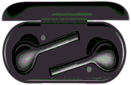
如图2所示,展示为本申请于一实施例中充电盒和适配该充电盒的TWS蓝牙耳机的结构 示意图。如图所示,图中包括:所述充电盒1与TWS蓝牙耳机2。As shown in FIG. 2, it shows a schematic structural diagram of a charging box and a TWS Bluetooth headset adapted to the charging box in an embodiment of the present application. As shown in the figure, the figure includes: the charging
充电盒1Charging
所述充电盒1包括:盒体11,所述盒体11内设置有适配TWS蓝牙耳机2结构的容纳腔111;所述容纳腔111的内壁上设有用于检测所述TWS蓝牙耳机2出/入盒状态的红外光感应组件1111,其根据是否检测到红外光线生成不同电平信号。The
所述盒体11内设有充电电路;所述容纳腔111底部设有连接器组件112,其分别电性连 接于所述充电电路的正极与负极。The
MCU模块,分别与所述红外光感应组件1111、及所述充电电路连接,用于接收所述红 外光感应组件1111生成的所述电平信号,并据以控制所述充电电路的通断。The MCU module is respectively connected with the infrared light sensing component 1111 and the charging circuit, and is used to receive the level signal generated by the infrared light sensing component 1111, and control the on-off of the charging circuit accordingly.
于本申请中,为解决机械开关的不灵敏以及HALL元件带来的额外干扰,本申请提出了 利用红外光线检测的方式,具体为红外光感应组件1111。In the present application, in order to solve the insensitivity of the mechanical switch and the additional interference caused by the HALL element, the present application proposes a method of detecting infrared light, specifically the infrared light sensing component 1111 .
于本申请一实施例中,所述红外光感应组件1111包括:红外光发射二极管、及红外感应 管;所述红外光发射二极管与所述红外感应管分别对称设于所述容纳腔111的内壁上同一水 平高度的两相对位置上。In an embodiment of the present application, the infrared light sensing component 1111 includes: an infrared light emitting diode and an infrared sensing tube; the infrared light emitting diode and the infrared sensing tube are symmetrically disposed on the inner wall of the
于本申请中,所述红外光发射二极管用于启动后发生红外光线,所述红外感应管用于检 测红外光线。并且,为保证检测的准确性,将所述红外光发射二极管与所述红外感应管设置 在所述容纳腔111的内壁上同一水平高度的对称两相对位置上。In the present application, the infrared light emitting diode is used to generate infrared light after being activated, and the infrared induction tube is used to detect the infrared light. In addition, in order to ensure the accuracy of detection, the infrared light emitting diode and the infrared induction tube are arranged on the inner wall of the
需要说明的是,由于所述容纳腔111空间比较狭小,所述红外光发射二极管与所述红外 感应管可以是片状的红外光发射片,或红外感应片。或者所述红外光发射二极管与所述红外 感应管为内嵌于所述容纳腔111内壁中,不影响所述容纳腔111整体空间,并且不影响红外 光线的发射与检测。It should be noted that, since the space of the
于本实施例中,本申请利用红外光发射二极管和红外感应管组合来实现TWS蓝牙耳机2 出入盒的检测。当红外二极管发射红外光线时候,红外感应管接收到红外光线。当TWS蓝牙 耳机2放入充电盒1中,所述红外光线会被所述TWS蓝牙耳机2遮挡,红外感应管则无法接 收到红外光线,基于此来检测所述TWS蓝牙耳机2的出入盒动作。In this embodiment, the present application uses a combination of an infrared light emitting diode and an infrared induction tube to realize the detection of the
需说明的是,本申请通过设置所述容纳腔111直径与所述TWS蓝牙耳机2的直径相适配, 即容纳腔111直径接近或略大于所述TWS蓝牙耳机2的直径。以确保所述TWS蓝牙耳机2 在放入所述容纳腔111时,所述红外二极管发射的红外光线不会因折射或反射而被所述红外 感应管检测到。It should be noted that, in the present application, the diameter of the
于本申请一实施例中,所述连接器组件112为Pogo Pin连接器组件或插针连接器组件, 所述连接器组件112与放入所述盒体11的所述TWS蓝牙耳机2上设置的所述连接器组件221 相适配,所述Pogo Pin连接器组件为触点式连接器。In an embodiment of the present application, the
于本实施例中,所述MCU模块与所述充电电路电性连接,由于所述红外光感应组件1111 在检测到红外光线与未检测到宫外光线产生不同的电平信号。如TWS蓝牙耳机2放入充电盒 1时,TWS蓝牙耳机2会阻挡红外光发射二极管发射的红外光线,红外感应管无法检测到红 外管光线,此时可生成一高电平信号;反之,若TWS蓝牙耳机2放从充电盒1取出时,TWS 蓝牙耳机2不会阻挡红外光发射二极管发射的红外光线,红外感应管可以检测到红外管光线, 此时可生成一低电平信号,那么所述MCU模块可以具不同的电平信号作为所述TWS蓝牙耳 机2出盒或入盒的判断,从而控制所述充电电路的通断,以减少不必要的功耗。In this embodiment, the MCU module is electrically connected to the charging circuit, because the infrared light sensing component 1111 generates signals of different levels when infrared light is detected and extrauterine light is not detected. For example, when the
于本申请中,所述充电盒1具有两种结构的实施例,一种是以所述TWS蓝牙耳机2充当 所述充电盒1的盖体,另一种是,所述充电盒1对应盒体11还配设有盖体12。In this application, the
第一实施例first embodiment
如图3所示,展示为本申请于一实施中无盖充电盒和适配该充电盒的TWS蓝牙耳机的结 构示意图。As shown in FIG. 3 , a schematic structural diagram of a lidless charging box and a TWS Bluetooth headset adapted to the charging box in an implementation of the present application is shown.
于第一实施例中,所述容纳腔111入口边缘处设有霍尔元件113,对应所述TWS蓝牙耳 机2上设置有磁铁211;当所述霍尔元件113与所述磁铁211吸合时,所述霍尔元件113断开, 并通过所述磁铁211吸合所述霍尔元件113以固定放入所述容纳腔111内的所述TWS蓝牙耳 机2;当所述霍尔元件113与所述磁铁211分离时,所述霍尔元件113导通。In the first embodiment, a
本实施例中,所述容纳腔111入口边缘处,可以是位于所述盒体11顶部表面靠近所述容 纳腔111的位置,也可以是位于容纳腔111内靠近入口位置。In this embodiment, the edge of the entrance of the
如图所示,所述盒体11充当充电盒1,所述TWS蓝牙耳机2的顶部充当如图2中所述充电盒1的盖体12。所述盒体11设有所述容纳腔111,所述容纳腔入111口边缘处设有霍尔元件113,所述TWS蓝牙耳机2的顶部设有磁铁211。当所述TWS蓝牙耳机2插入所述容纳 腔111时,所述霍尔元件113会与所述磁铁211吸合,以起到固定作用,并且此时所述霍尔 元件113导通;当取出所述TWS蓝牙耳机2时,所述霍尔元件113会与所述磁铁211分离, 此时所述霍尔元件113断开。As shown in the figure, the
通过在所述容纳腔111入口边缘处设置霍尔元件113,并对应的在所述TWS蓝牙耳机2 上设置磁铁211,一方面,通过所述霍尔元件113与所述磁铁211的远近变化使所述霍尔元件 113发生断开或导通的变化;另一方面,还利用所述霍尔元件113与所述磁铁211之间的磁性, 通过接触时的吸合使所述TWS蓝牙耳机2起到充当如图2中所述充电盒1的盖体12。By arranging the
需说明的是,所述霍尔元件113与所述MCU模块电性连接,可使所述MCU模块获取所述霍尔元件113为断开或导通的状态,从而还可以进一步令所述充电盒1判断所述TWS蓝牙耳机2的出盒或入盒的情况。It should be noted that, the
第二实施例Second Embodiment
如图2所示,所述充电盒1还包括:与所述盒体11适配的盖体12,所述盖体12与所述盒体11盖合以固定放入所述容纳腔111内的所述TWS蓝牙耳机2。As shown in FIG. 2 , the
本实施例中,所述盒体11与所述盖体12,其具体为铰接式的组合。除了这种结构,还 可参考如图4A与4B所示的分离式与旋转式组合。In this embodiment, the
于本申请一实施例中,所述盖体12与所述盒体11对应盖合位置分别设有磁铁121与霍 尔元件113;其中,当所述霍尔元件113与所述磁铁121吸合时,所述霍尔元件113断开;当 所述霍尔元件113与所述磁铁121分离时,所述霍尔元件113导通。In an embodiment of the present application, the
本实施例中,通过在所述容纳腔111入口边缘处设置霍尔元件113,并对应的在所述TWS 蓝牙耳机2上设置磁铁121,通过所述霍尔元件113与所述磁铁121的远近变化使所述霍尔 元件113发生断开或导通的变化。In this embodiment, by disposing a
需说明的是,所述霍尔元件113与所述MCU模块电性连接,以使所述MCU模块获取所述霍尔元件113为断开或导通的状态。It should be noted that, the
需说明的是,因MCU模块、及充电电路,以及下文的通信模块不局限于具体结构,因此上述图2、图3、图4A、图4B中均未画出,但应理解的是,所述MCU模块、充电电路、 及通信模块是存在于本申请所述的充电盒1中。It should be noted that, because the MCU module, the charging circuit, and the communication module below are not limited to specific structures, the above-mentioned Fig. 2, Fig. 3, Fig. 4A, and Fig. 4B are not drawn, but it should be understood that all The MCU module, the charging circuit, and the communication module are present in the
如图5所示,展示为本申请于一实施例中所述充电盒的模块示意图。对应第一实施例或 第二实施例,所述充电盒还包括通信模块503,并且通过MCU模块504还可实现对应不同情 况的控制功能。如图所示,所述红外感应组件501、所述充电电路502、所述通信模块503, 分别与所述MCU模块504电性连接。As shown in FIG. 5 , a schematic diagram of a module of the charging case described in an embodiment of the present application is shown. Corresponding to the first embodiment or the second embodiment, the charging box further includes a
具体来说,可参见图6所示的红外感应组件的电路示意图,如图所示,所述红外感应组 件501包括:红外光发射二极管、及红外感应管、多个电阻、三极管。Specifically, please refer to the schematic circuit diagram of the infrared sensing assembly shown in FIG. 6. As shown in the figure, the
具体来说,所述充电盒1还包括:通信模块503,用于通信连接所述TWS蓝牙耳机;Specifically, the
所述MCU模块503,还用于当检测到如图2或图3中所述霍尔元件113导通时,开启所述红外光感应组件501;并依据所述红外光感应组件501生成的所述电平信号判断其是否检测到所述红外光线;若未检测到所述红外光线,则令所述充电电路502导通以进行放电,并向所述TWS蓝牙耳机发送待机指令;若检测到所述红外光线,则向所述TWS蓝牙耳机发送 运行指令;The
和/或,当检测到如图2或图3中所述霍尔元件113断开时,依据所述红外光感应组件501 生成的所述电平信号判断其是否检测到所述红外光线;若检测到所述红外光线,则关闭所述 红外光感应组件501,并令所述充电电路502断开;若为检测到所述红外光线,则令所述充 电电路502导通以进行放电,并向所述TWS蓝牙耳机发送待机指令。And/or, when it is detected that the
本实施例中,所述通信模块503主要用于与所述TWS蓝牙耳机通信,更具体地,通过所 述MCU模块504向所述TWS蓝牙耳机发送如电机指令或运行指令。In this embodiment, the
所述通信模块503可以是一个或多个无线通讯方式及其组合。通信方式包括:互联网、 CAN、内联网、广域网(WAN)、局域网(LAN)、无线网络、数字用户线(DSL)网络、帧中继网络、异步传输模式(ATM)网络、虚拟专用网络(VPN)和/或任何其它合适的通信网络中的任何一个或多个。例如:WIFI、蓝牙、NFC、GPRS、GSM、及以太网中任意一种及多种组合。The
于一些实施例中,所述MCU模块504可以是通用处理器,包括中央处理器(CentralProcessing Unit,简称CPU)、网络处理器(Network Processor,简称NP)、为微处理器等;还可以是数字信号处理器(Digital Signal Processing,简称DSP)、专用集成电路(Application Specific Integrated Circuit,简称ASIC)、现场可编程门阵列(Field-Programmable Gate Array, 简称FPGA)或者其他可编程逻辑器件、分立门或者晶体管逻辑器件、分立硬件组件。In some embodiments, the
于本实施例中,由上述可知,通过红外光感应组件501是否检测到红外光线,可以间接 判断所述TWS蓝牙耳机的出入盒情况,由如图2或图3中所述霍尔元件113的导通或断开状 态,基于此,所述MCU模块504可以实现对应不同场景的功能。In this embodiment, it can be seen from the above that whether the infrared
再结合图2或图3,举例来说,首先通过所述霍尔元件113的导通或断开状态,来判断 如图2中所述盖体12的是否打开,或对应第一实施例(对应图3)则是判断充当如图2中盖体12的所述TWS蓝牙耳机2是否打开。Referring to FIG. 2 or FIG. 3 , for example, firstly, it is determined whether the
假设此时所述霍尔元件113导通,即可判断此时所述盖体12打开,那么实际场景中,接 下来可能是放入TWS蓝牙耳机2充电或取出TWS蓝牙耳机2使用,为判断准确,则需要开 启所述红外光感应组件1111,并依据所述红外光感应组件1111生成的所述电平信号判断其是 否检测到所述红外光线。Assuming that the
若未检测到所述红外光线,则可以判断出所述盒体11中有所述TWS蓝牙耳机2,即所 述TWS蓝牙耳机2为入盒状态,那么则令所述充电电路导通以进行放电,并向所述TWS蓝牙耳机2发送待机指令,以减少所述TWS蓝牙耳机2的功耗。If the infrared light is not detected, it can be determined that there is the
若检测到所述红外光线,则可以判断出所述盒体11中没有所述TWS蓝牙耳机2,即所 述TWS蓝牙耳机2为出盒状态,则向所述TWS蓝牙耳机2发送运行指令,以令其开始工作。If the infrared light is detected, it can be determined that the
再举例来说,假设此时所述霍尔元113件断开,,即可判断此时所述盖体12关闭,那么 实际场景中,接下来可能是已经放入TWS蓝牙耳机2充电或已经取出TWS蓝牙耳机2使用,由于所述红外光感应组件1111还处于打开状态(除出厂时),为判断准确,此时还需要通过所述红外光感应组件1111判断其是否检测到所述红外光线。For another example, assuming that the
若检测到所述红外光线,则说明所述TWS蓝牙耳机2此时为出盒状态,为减少所述红外 光感应组件1111以及所述充电电路不必要的功耗,关闭所述红外光感应组件1111,并令所述 充电电路断开,因为在判断所述盖体12打开时,在所述TWS蓝牙耳机2为出盒状态对其发 送过开机指令,故此处不再发送开机指令。If the infrared light is detected, it means that the
若未检测到所述红外光线,则说明所述TWS蓝牙耳机2此时为入盒状态,则令所述充电 电路导通以进行放电,并向所述TWS蓝牙耳机2发送待机指令,以使所述TWS蓝牙耳机待 机。If the infrared light is not detected, it means that the
由所述MCU模块可执行上述功能,即能够基本实现日常使用TWS蓝牙耳机2与充电盒1之间使用的需求与判断。The above functions can be performed by the MCU module, that is, the needs and judgments of daily use between the
于一些实施例中,还可以在所述盒体11外表面设置指示灯,以提示各种状态,如量红灯 表在充电,量路灯表示充电完成。In some embodiments, an indicator light may also be provided on the outer surface of the
于本申请一实施中,本申请还提供与所述充电盒1相适配的一种TWS蓝牙耳机2,参考 图2或图3所示,所述TWS蓝牙耳机2包括:耳机主体21、耳机柱体22、通信模块、及 MCU模块;In an implementation of the present application, the present application also provides a
所述耳机柱体22底部设有连接器组件221,其与所述充电盒1内设置的连接器组件112 相适配以用于充电。A
于本申请一实施例中,所述连接器组件221为Pogo Pin连接器组件或插槽连接器组件, 其与所述充电盒1的所述连接器组件112相适配。In an embodiment of the present application, the
于本实施例中,所述Pogo Pin连接器组件为触点式连接器。所述连接器组件221可以为 插槽式连接器组件。In this embodiment, the Pogo Pin connector assembly is a contact type connector. The
所述通信模块,用于与所述充电盒1通信连接,以接收所述充电盒1发送的待机指令或 运行指令;The communication module is used to communicate with the
所述MCU模块,用于依据接收的所述待机指令以令所述耳机主体21待机,或依据接收 到的所述运行指令以令所述耳机主体21运行。The MCU module is configured to make the earphone
具体可参见图2中所述充电盒1对应所述MCU模块执行的相应功能,此处不再赘述。For details, please refer to the corresponding functions performed by the
于本申请一实施例中,参见图3所示,所述耳机主体21顶部对应所述充电盒1中容纳腔 111入口边缘处设有磁体211,以与所述充电盒1上设置的霍尔元件113相适配以吸合。In an embodiment of the present application, as shown in FIG. 3 , a
于本实施例中,对应本申请的第一实施例,所述TWS蓝牙耳机上2设置磁铁211以对应 所述充电盒1中所述容纳腔111入口边缘处设置霍尔元件113。In this embodiment, corresponding to the first embodiment of the present application, a
一方面,通过所述霍尔元件113与所述磁铁211的远近变化使所述霍尔元件113发生断 开或导通的变化;另一方面,还利用所述霍尔元件113与所述磁铁211之间的磁性,通过接 触时的吸合使所述TWS蓝牙耳机2起到充当所述充电盒1的盖体。On the one hand, the
本申请还提供一种TWS蓝牙耳机与充电盒组件,可参见图2或图3所示的组件,所述组 件包括:如图2、图4A、及T图4B中任意一个图中的所述的充电盒1、及与其适配的如图2或图3所述的TWS蓝牙耳机2。The present application also provides a TWS Bluetooth headset and charging box assembly, please refer to the assembly shown in FIG. 2 or FIG. 3 , the assembly includes: as described in any one of FIG. 2 , FIG. 4A , and FIG. 4B The
综上所述,本申请提供的一种充电盒和适配该充电盒的TWS蓝牙耳机、及其组件。本申 请有效克服了现有技术中的种种缺点而具高度产业利用价值。To sum up, the present application provides a charging box, a TWS Bluetooth headset adapted to the charging box, and components thereof. The present application effectively overcomes various shortcomings in the prior art and has high industrial application value.
上述实施例仅例示性说明本申请的原理及其功效,而非用于限制本申请。任何熟悉此技 术的人士皆可在不违背本申请的精神及范畴下,对上述实施例进行修饰或改变。因此,举凡 所属技术领域中包含通常知识者在未脱离本申请所揭示的精神与技术思想下所完成的一切等 效修饰或改变,仍应由本申请的权利要求所涵盖。The above-mentioned embodiments merely illustrate the principles and effects of the present application, but are not intended to limit the present application. Any person skilled in the art can modify or change the above-mentioned embodiments without departing from the spirit and scope of the present application. Therefore, all equivalent modifications or changes made by those of ordinary skill in the technical field without departing from the spirit and technical idea disclosed in the present application should still be covered by the claims of the present application.
Claims (10)
Priority Applications (1)
| Application Number | Priority Date | Filing Date | Title |
|---|---|---|---|
| CN201910556432.3A CN112135212A (en) | 2019-06-25 | 2019-06-25 | Charging box and TWS Bluetooth headset adapting same, and assembly thereof |
Applications Claiming Priority (1)
| Application Number | Priority Date | Filing Date | Title |
|---|---|---|---|
| CN201910556432.3A CN112135212A (en) | 2019-06-25 | 2019-06-25 | Charging box and TWS Bluetooth headset adapting same, and assembly thereof |
Publications (1)
| Publication Number | Publication Date |
|---|---|
| CN112135212A true CN112135212A (en) | 2020-12-25 |
Family
ID=73850124
Family Applications (1)
| Application Number | Title | Priority Date | Filing Date |
|---|---|---|---|
| CN201910556432.3A Pending CN112135212A (en) | 2019-06-25 | 2019-06-25 | Charging box and TWS Bluetooth headset adapting same, and assembly thereof |
Country Status (1)
| Country | Link |
|---|---|
| CN (1) | CN112135212A (en) |
Cited By (4)
| Publication number | Priority date | Publication date | Assignee | Title |
|---|---|---|---|---|
| CN113002939A (en) * | 2021-03-03 | 2021-06-22 | 读书郎教育科技有限公司 | Telephone watch collection device and method capable of saving watch power consumption |
| CN113253855A (en) * | 2021-03-15 | 2021-08-13 | 荣耀终端有限公司 | Electronic equipment assembly |
| CN116311832A (en) * | 2022-12-30 | 2023-06-23 | 广东小天才科技有限公司 | Wireless earphone loss alarm method and system |
| US20230208175A1 (en) * | 2021-12-23 | 2023-06-29 | Advanced Semiconductor Engineering, Inc. | Electronic device with electromagnet |
Citations (7)
| Publication number | Priority date | Publication date | Assignee | Title |
|---|---|---|---|---|
| CN106617580A (en) * | 2015-09-30 | 2017-05-10 | 苹果公司 | Case for charging and securing portable listening devices |
| CN206212223U (en) * | 2016-09-30 | 2017-05-31 | 歌尔科技有限公司 | A kind of charging box of wireless headset and the wireless headset for being adapted to the charging box |
| CN208174945U (en) * | 2018-05-15 | 2018-11-30 | 上海巨微集成电路有限公司 | The TWS earphone charging box of carried charge push function |
| CN109413536A (en) * | 2018-12-20 | 2019-03-01 | 歌尔科技有限公司 | A kind of wireless headset enters box detection method, device and wireless headset charging box |
| CN109862459A (en) * | 2019-03-07 | 2019-06-07 | 歌尔科技有限公司 | A kind of TWS Headphone device |
| CN209002183U (en) * | 2018-12-21 | 2019-06-18 | 歌尔科技有限公司 | A kind of earphone enters box detection circuit and Earphone box |
| CN210042129U (en) * | 2019-06-25 | 2020-02-07 | 上海宽翼通信科技股份有限公司 | Charging box and TWS Bluetooth headset adapting same, and assembly thereof |
-
2019
- 2019-06-25 CN CN201910556432.3A patent/CN112135212A/en active Pending
Patent Citations (7)
| Publication number | Priority date | Publication date | Assignee | Title |
|---|---|---|---|---|
| CN106617580A (en) * | 2015-09-30 | 2017-05-10 | 苹果公司 | Case for charging and securing portable listening devices |
| CN206212223U (en) * | 2016-09-30 | 2017-05-31 | 歌尔科技有限公司 | A kind of charging box of wireless headset and the wireless headset for being adapted to the charging box |
| CN208174945U (en) * | 2018-05-15 | 2018-11-30 | 上海巨微集成电路有限公司 | The TWS earphone charging box of carried charge push function |
| CN109413536A (en) * | 2018-12-20 | 2019-03-01 | 歌尔科技有限公司 | A kind of wireless headset enters box detection method, device and wireless headset charging box |
| CN209002183U (en) * | 2018-12-21 | 2019-06-18 | 歌尔科技有限公司 | A kind of earphone enters box detection circuit and Earphone box |
| CN109862459A (en) * | 2019-03-07 | 2019-06-07 | 歌尔科技有限公司 | A kind of TWS Headphone device |
| CN210042129U (en) * | 2019-06-25 | 2020-02-07 | 上海宽翼通信科技股份有限公司 | Charging box and TWS Bluetooth headset adapting same, and assembly thereof |
Cited By (6)
| Publication number | Priority date | Publication date | Assignee | Title |
|---|---|---|---|---|
| CN113002939A (en) * | 2021-03-03 | 2021-06-22 | 读书郎教育科技有限公司 | Telephone watch collection device and method capable of saving watch power consumption |
| CN113253855A (en) * | 2021-03-15 | 2021-08-13 | 荣耀终端有限公司 | Electronic equipment assembly |
| US12197655B2 (en) | 2021-03-15 | 2025-01-14 | Honor Device Co., Ltd. | Electronic device component |
| US20230208175A1 (en) * | 2021-12-23 | 2023-06-29 | Advanced Semiconductor Engineering, Inc. | Electronic device with electromagnet |
| US12316151B2 (en) * | 2021-12-23 | 2025-05-27 | Advanced Semiconductor Engineering, Inc. | Electronic device with electromagnet |
| CN116311832A (en) * | 2022-12-30 | 2023-06-23 | 广东小天才科技有限公司 | Wireless earphone loss alarm method and system |
Similar Documents
| Publication | Publication Date | Title |
|---|---|---|
| CN210042129U (en) | Charging box and TWS Bluetooth headset adapting same, and assembly thereof | |
| CN112135212A (en) | Charging box and TWS Bluetooth headset adapting same, and assembly thereof | |
| CN106998511B (en) | Wireless earphone assembly, storage box in wireless earphone assembly, and wireless earphone | |
| CN106559721B (en) | Wireless pairing of earbuds and case | |
| CN108540891A (en) | A kind of Earphone box and its control method | |
| CN107809697B (en) | Earphone box for establishing interaction with wireless earphone | |
| WO2020007222A1 (en) | Method for controlling earphone switching, earphone, and earphone system | |
| CN108696783A (en) | With the wired of the earphone for facilitating charging with it is wireless between the method and apparatus that easily switch | |
| CN105487899B (en) | Wearing state method for reporting, system and earphone for earphone | |
| WO2020108059A1 (en) | Earphone and worn detection device thereof | |
| JP2013511953A5 (en) | ||
| CN112449259B (en) | Earphone pairing method and terminal | |
| CN109587592A (en) | Bluetooth headset and its on-off control method | |
| CN108141655B (en) | Smart device with separable body | |
| CN108076210A (en) | The screen backlight control system and method for smart machine | |
| CN106532971B (en) | Wireless charging method and device | |
| DK201970126A1 (en) | CASE WITH MAGNETIC OVER-CENTER MECHANISM | |
| CN203482246U (en) | Mobile terminal device | |
| WO2020200005A1 (en) | Connector, electronic apparatus, and data transmission method and device | |
| CN108649672A (en) | Wireless charging circuit and wearable equipment | |
| CN110707782A (en) | Charging control circuit, charging communication circuit, electronic device, and charging control method | |
| CN203205677U (en) | Charging adapter of mobile communication terminal and charging assembly thereof | |
| CN108668204B (en) | Multiplexing circuit, wearable device and wearable device working mode switching method | |
| CN207965620U (en) | A kind of intelligent household terminal | |
| CN212305628U (en) | TWS bluetooth headset box and TWS bluetooth headset that charges |
Legal Events
| Date | Code | Title | Description |
|---|---|---|---|
| PB01 | Publication | ||
| PB01 | Publication | ||
| SE01 | Entry into force of request for substantive examination | ||
| SE01 | Entry into force of request for substantive examination | ||
| RJ01 | Rejection of invention patent application after publication | ||
| RJ01 | Rejection of invention patent application after publication |
Application publication date: 20201225 |