CN112089961B - Microneedle patch applicator and housing therefor - Google Patents

Microneedle patch applicator and housing therefor Download PDF

Info

Publication number
CN112089961B
CN112089961B CN202010965959.4A CN202010965959A CN112089961B CN 112089961 B CN112089961 B CN 112089961B CN 202010965959 A CN202010965959 A CN 202010965959A CN 112089961 B CN112089961 B CN 112089961B
Authority
CN
China
Prior art keywords
skin
housing
applicator
microneedle patch
patch
Prior art date
Legal status (The legal status is an assumption and is not a legal conclusion. Google has not performed a legal analysis and makes no representation as to the accuracy of the status listed.)
Active
Application number
CN202010965959.4A
Other languages
Chinese (zh)
Other versions
CN112089961A (en
Inventor
小林胜则
滨本英利
Current Assignee (The listed assignees may be inaccurate. Google has not performed a legal analysis and makes no representation or warranty as to the accuracy of the list.)
MedRx Co Ltd
Original Assignee
MedRx Co Ltd
Priority date (The priority date is an assumption and is not a legal conclusion. Google has not performed a legal analysis and makes no representation as to the accuracy of the date listed.)
Filing date
Publication date
Priority claimed from PCT/JP2015/085707 external-priority patent/WO2016129184A1/en
Application filed by MedRx Co Ltd filed Critical MedRx Co Ltd
Publication of CN112089961A publication Critical patent/CN112089961A/en
Application granted granted Critical
Publication of CN112089961B publication Critical patent/CN112089961B/en
Active legal-status Critical Current
Anticipated expiration legal-status Critical

Links

Images

Classifications

    • AHUMAN NECESSITIES
    • A61MEDICAL OR VETERINARY SCIENCE; HYGIENE
    • A61MDEVICES FOR INTRODUCING MEDIA INTO, OR ONTO, THE BODY; DEVICES FOR TRANSDUCING BODY MEDIA OR FOR TAKING MEDIA FROM THE BODY; DEVICES FOR PRODUCING OR ENDING SLEEP OR STUPOR
    • A61M37/00Other apparatus for introducing media into the body; Percutany, i.e. introducing medicines into the body by diffusion through the skin
    • A61M37/0015Other apparatus for introducing media into the body; Percutany, i.e. introducing medicines into the body by diffusion through the skin by using microneedles
    • AHUMAN NECESSITIES
    • A61MEDICAL OR VETERINARY SCIENCE; HYGIENE
    • A61MDEVICES FOR INTRODUCING MEDIA INTO, OR ONTO, THE BODY; DEVICES FOR TRANSDUCING BODY MEDIA OR FOR TAKING MEDIA FROM THE BODY; DEVICES FOR PRODUCING OR ENDING SLEEP OR STUPOR
    • A61M37/00Other apparatus for introducing media into the body; Percutany, i.e. introducing medicines into the body by diffusion through the skin
    • AHUMAN NECESSITIES
    • A61MEDICAL OR VETERINARY SCIENCE; HYGIENE
    • A61KPREPARATIONS FOR MEDICAL, DENTAL OR TOILETRY PURPOSES
    • A61K9/00Medicinal preparations characterised by special physical form
    • A61K9/0012Galenical forms characterised by the site of application
    • A61K9/0019Injectable compositions; Intramuscular, intravenous, arterial, subcutaneous administration; Compositions to be administered through the skin in an invasive manner
    • A61K9/0021Intradermal administration, e.g. through microneedle arrays or needleless injectors
    • AHUMAN NECESSITIES
    • A61MEDICAL OR VETERINARY SCIENCE; HYGIENE
    • A61MDEVICES FOR INTRODUCING MEDIA INTO, OR ONTO, THE BODY; DEVICES FOR TRANSDUCING BODY MEDIA OR FOR TAKING MEDIA FROM THE BODY; DEVICES FOR PRODUCING OR ENDING SLEEP OR STUPOR
    • A61M37/00Other apparatus for introducing media into the body; Percutany, i.e. introducing medicines into the body by diffusion through the skin
    • A61M37/0015Other apparatus for introducing media into the body; Percutany, i.e. introducing medicines into the body by diffusion through the skin by using microneedles
    • A61M2037/0023Drug applicators using microneedles
    • AHUMAN NECESSITIES
    • A61MEDICAL OR VETERINARY SCIENCE; HYGIENE
    • A61MDEVICES FOR INTRODUCING MEDIA INTO, OR ONTO, THE BODY; DEVICES FOR TRANSDUCING BODY MEDIA OR FOR TAKING MEDIA FROM THE BODY; DEVICES FOR PRODUCING OR ENDING SLEEP OR STUPOR
    • A61M37/00Other apparatus for introducing media into the body; Percutany, i.e. introducing medicines into the body by diffusion through the skin
    • A61M37/0015Other apparatus for introducing media into the body; Percutany, i.e. introducing medicines into the body by diffusion through the skin by using microneedles
    • A61M2037/0053Methods for producing microneedles

Landscapes

  • Health & Medical Sciences (AREA)
  • Engineering & Computer Science (AREA)
  • Dermatology (AREA)
  • Medical Informatics (AREA)
  • Anesthesiology (AREA)
  • Biomedical Technology (AREA)
  • Heart & Thoracic Surgery (AREA)
  • Hematology (AREA)
  • Life Sciences & Earth Sciences (AREA)
  • Animal Behavior & Ethology (AREA)
  • General Health & Medical Sciences (AREA)
  • Public Health (AREA)
  • Veterinary Medicine (AREA)
  • Media Introduction/Drainage Providing Device (AREA)

Abstract

本发明的目的是提供提高了针对于皮肤的垂直侵入性的微针贴片施用器及微针贴片施用器用壳体。微针贴片施用器用壳体(11)由一个片或膜形成,并且具有:平坦的外周基部(12);以及隆起部(13),被外周基部包围且相对于外周基部向从下部面朝向上部面的垂直上方鼓起。隆起部的下部面部分构成微针贴片支承面(42)。隆起部具备多个谷折部(24),谷折部具有朝向远离隆起部的中心部的方向的谷底。

Figure 202010965959

An object of the present invention is to provide a microneedle patch applicator and a housing for a microneedle patch applicator with improved vertical invasiveness to the skin. A housing (11) for a microneedle patch applicator is formed of a sheet or film and has: a flat peripheral base (12); and a raised portion (13) surrounded by the peripheral base and facing from below with respect to the peripheral base Bulge up vertically above the upper face. The lower surface portion of the protuberance constitutes a microneedle patch support surface (42). The raised portion includes a plurality of valley folds (24), and the valley folded portion has a valley bottom facing in a direction away from the center portion of the raised portion.

Figure 202010965959

Description

微针贴片施用器及其壳体Microneedle patch applicator and housing thereof

本申请是申请日为2016年12月20日、申请号为201680074673.9、发明名称为“微针贴片施用器及其壳体”的发明申请的分案申请。This application is a divisional application of an invention application with an application date of December 20, 2016, an application number of 201680074673.9, and an invention title of "Microneedle Patch Applicator and its Housing".

技术领域technical field

本发明涉及贴附于动物(包括人及人以外的动物)的皮肤的微针贴片施用器(microneedle patch applicator)。本发明还涉及微针贴片施用器用壳体。The present invention relates to a microneedle patch applicator that is attached to the skin of animals (including humans and animals other than humans). The present invention also relates to a housing for a microneedle patch applicator.

背景技术Background technique

近年来,作为经皮吸收型给药系统之一,利用药物涂敷型微针贴片的给药系统备受瞩目(参照专利文献1~7)。在该微针贴片的基材上高密度地形成有数百微米长度的纤细的突起或针,通过将表面或内部中载置有靶向药剂(如疫苗、蛋白质、肽等分子)的针刺入皮肤,来直接向真皮或表皮输送药剂,因此具有如下诸多优点:不像内服药那样对肝脏有负担,不像注射剂一样具有伴随针的侵入而带来的疼痛,并且可减轻因暂时的过量的药剂吸收导致的副作用等。In recent years, as one of the transdermal drug delivery systems, a drug delivery system using a drug-coated microneedle patch has attracted attention (see Patent Documents 1 to 7). On the substrate of the microneedle patch, slender protrusions or needles with lengths of several hundreds of micrometers are formed at a high density, and the needles with targeting agents (such as vaccines, proteins, peptides, etc.) are loaded on the surface or in the interior. It penetrates the skin to directly deliver the drug to the dermis or epidermis, so it has the following advantages: it does not burden the liver like an oral drug, does not have the pain associated with the penetration of a needle like an injection, and can reduce temporary pain caused by Side effects caused by excessive drug absorption, etc.

微针贴片的针非常纤细(根部的直径为约数十微米)。因此,有可能因侵入皮肤时的阻力而损坏或折损。在由金属(例如钛)形成的针的情况下,因皮肤内折损而留置在体内的风险是大问题。在由生物降解性树脂形成针的情况下,与金属针相比,破损或折损的可能性更高。尤其是,当针相对于皮肤倾斜时,针相对于皮肤的插入性下降,或者弯曲力作用于针,因此容易折断。因此,需要可将针相对于皮肤垂直地穿刺,进而可靠地将微针贴片贴附于皮肤的方法。The needles of the microneedle patch are very thin (about tens of microns in diameter at the root). Therefore, there is a possibility of damage or breakage due to resistance when penetrating the skin. In the case of needles formed of metal (eg titanium), the risk of indwelling in the body due to breakage in the skin is a big problem. When the needle is formed of a biodegradable resin, the possibility of breakage or breakage is higher than that of a metal needle. In particular, when the needle is inclined with respect to the skin, the insertability of the needle with respect to the skin decreases, or a bending force acts on the needle, so that the needle is easily broken. Therefore, there is a need for a method in which the needle can be pierced perpendicularly to the skin, thereby reliably attaching the microneedle patch to the skin.

(现有技术文献)(Prior Art Literature)

(专利文献)(patent literature)

专利文献1:日本特开2006-149818号公报Patent Document 1: Japanese Patent Laid-Open No. 2006-149818

专利文献2:日本特表2008-520369号公报Patent Document 2: Japanese Patent Publication No. 2008-520369

专利文献3:日本特表2008-543528号公报Patent Document 3: Japanese Patent Publication No. 2008-543528

专利文献4:日本特表2008-535587号公报Patent Document 4: Japanese Patent Publication No. 2008-535587

专利文献5:日本特表2010-516337号公报Patent Document 5: Japanese Patent Publication No. 2010-516337

专利文献6:日本再表2009-107806号公报Patent Document 6: Japanese Publication No. 2009-107806

专利文献7:日本再表2011-089907号公报Patent Document 7: Japanese Publication No. 2011-089907

发明内容SUMMARY OF THE INVENTION

(发明所要解决的问题)(The problem to be solved by the invention)

本发明提供能够提高针相对于皮肤的垂直侵入性,进而能够可靠地将微针贴片贴附于皮肤的微针贴片施用器及微针贴片施用器用壳体。The present invention provides a microneedle patch applicator and a housing for the microneedle patch applicator, which can improve the vertical penetration of a needle with respect to the skin, thereby enabling the microneedle patch to be reliably attached to the skin.

(用于解决问题的方案)(a solution to the problem)

在本发明的微针贴片施用器用壳体的实施方式中,由具有上部面和下部面的一个片或膜构成,具备壳体,所述壳体包括:平坦的外周基部;以及隆起部,被所述外周基部包围且相对于所述外周基部向从所述下部面朝向所述上部面的垂直上方鼓起,所述隆起部的下部面部分构成用于支承微针贴片的面,所述隆起部具备多个谷折部,所述谷折部具有朝向远离所述隆起部的中心部的方向的谷底。In an embodiment of the housing for a microneedle patch applicator of the present invention, it is composed of one sheet or film having an upper surface and a lower surface, and includes a housing including: a flat outer peripheral base; and a raised portion, Surrounded by the outer peripheral base and bulged vertically upward from the lower surface toward the upper surface with respect to the outer peripheral base, the lower surface portion of the bulge portion constitutes a surface for supporting the microneedle patch, so The raised portion includes a plurality of valley folds having valley bottoms facing in a direction away from the center portion of the raised portion.

在微针贴片施用器用壳体的另一实施方式中,所述谷折部被配置为相对于与穿过所述隆起部的中心的垂直轴z轴正交且彼此正交的两个水平轴x轴及y轴对称。In another embodiment of the housing for a microneedle patch applicator, the valley folds are configured relative to two horizontal z-axis orthogonal to a vertical axis z-axis passing through the center of the ridges and orthogonal to each other The x-axis and the y-axis are symmetrical.

在微针贴片施用器用壳体的另一实施方式中,所述谷折部被配置为相对于所述垂直轴z轴旋转对称(n次对称:n为2以上的整数)。In another embodiment of the housing for a microneedle patch applicator, the valley fold is arranged to be rotationally symmetric with respect to the vertical axis z-axis (n-fold symmetry: n is an integer of 2 or more).

在微针贴片施用器用壳体的另一实施方式中,所述隆起部呈相对于所述两个水平轴x轴及y轴中的至少一方的水平轴对称的形状。In another embodiment of the housing for a microneedle patch applicator, the raised portion has a shape that is symmetrical with respect to at least one of the two horizontal axes, the x-axis and the y-axis.

在微针贴片施用器用壳体的另一实施方式中,所述隆起部呈相对于所述两个水平轴x轴及y轴对称的形状。In another embodiment of the housing for a microneedle patch applicator, the protuberance has a symmetrical shape with respect to the two horizontal axes x-axis and y-axis.

在微针贴片施用器用壳体的另一实施方式中,所述隆起部呈以所述两个水平轴x轴及y轴中的一方的水平轴x轴为长轴而以所述两个水平轴中的另一方的水平轴y轴为短轴的形状。In another embodiment of the housing for a microneedle patch applicator, the raised portion has a horizontal axis x-axis of one of the two horizontal axes x-axis and y-axis as a long axis, and the two The other of the horizontal axes, the y-axis, is the shape of the short axis.

在微针贴片施用器用壳体的另一实施方式中,所述隆起部相对于穿过隆起部的中心的垂直轴z轴旋转对称(n次对称:n为2以上的整数)。In another embodiment of the housing for a microneedle patch applicator, the raised portion is rotationally symmetric with respect to the z-axis, a vertical axis passing through the center of the raised portion (n-fold symmetry: n is an integer of 2 or more).

在微针贴片施用器用壳体的另一实施方式中,所述隆起部在中央具有凹部,所述凹部的下部面部分构成用于支承微针贴片的面。In another embodiment of the housing for a microneedle patch applicator, the raised portion has a recessed portion in the center, and a lower surface portion of the recessed portion constitutes a surface for supporting the microneedle patch.

在微针贴片施用器用壳体的另一实施方式中,具备沿着所述隆起部的轮廓延伸并包围所述凹部的脊部,所述脊部具备多个所述谷折部。In another embodiment of the housing for a microneedle patch applicator, a ridge portion extending along the contour of the raised portion and surrounding the recessed portion is provided, and the ridge portion includes a plurality of the valley folds.

在微针贴片施用器用壳体的另一实施方式中,所述轮廓呈相对于所述两个水平轴x轴及y轴对称的形状。In another embodiment of the housing for a microneedle patch applicator, the profile is shaped symmetrically with respect to the two horizontal axes x-axis and y-axis.

在微针贴片施用器用壳体的另一实施方式中,所述轮廓呈以所述两个水平轴x轴及y轴中的一方的水平轴x轴为长轴,而以所述两个水平轴中的另一方的水平轴y轴为短轴的形状。In another embodiment of the housing for a microneedle patch applicator, the profile is such that the horizontal axis x axis of one of the two horizontal axes x axis and the y axis is the long axis, and the two horizontal axes x axis and the y axis are long axes. The other of the horizontal axes, the y-axis, is the shape of the short axis.

在微针贴片施用器用壳体的另一实施方式中,所述轮廓相对于所述垂直轴z轴旋转对称(n次对称:n为2以上的整数)。In another embodiment of the housing for a microneedle patch applicator, the profile is rotationally symmetric with respect to the vertical axis z-axis (n-fold symmetry: n is an integer of 2 or more).

在微针贴片施用器用壳体的另一实施方式中,所述凹部由平坦面构成,所述平坦面具有相对于所述短轴对称地配置且以平行于所述短轴y轴的方式延伸的两个易变形部,所述平坦面被划分为夹在所述两个易变形部之间的中央区域和位于所述中央区域的两侧的端部区域。In another embodiment of the housing for a microneedle patch applicator, the recess is constituted by a flat surface having a symmetrical arrangement with respect to the short axis and in a manner parallel to the short axis y-axis Extending two easily deformable parts, the flat surface is divided into a central area sandwiched between the two easily deformable parts and end areas located on both sides of the central area.

在微针贴片施用器用壳体的另一实施方式中,所述隆起部在以所述垂直轴z轴为中心的圆周方向上连续地配置。In another embodiment of the housing for a microneedle patch applicator, the protuberances are continuously arranged in the circumferential direction centered on the vertical axis z-axis.

在微针贴片施用器用壳体的另一实施方式中,所述隆起部在以所述垂直轴为中心的圆周方向上不连续地配置。In another embodiment of the housing for a microneedle patch applicator, the protuberances are arranged discontinuously in the circumferential direction centered on the vertical axis.

在微针贴片施用器用壳体的另一实施方式中,多个所述谷折部的至少一部分具有在远离所述隆起部的中心部的方向上向下方倾斜的谷底。In another embodiment of the housing for a microneedle patch applicator, at least a part of the plurality of valley folds has a valley bottom inclined downward in a direction away from a center portion of the raised portion.

在本发明的微针贴片施用器的实施方式中,具有如上所述的任一微针贴片施用器用壳体;以及被用于支承所述微针贴片的面支承的微针贴片。In an embodiment of the microneedle patch applicator of the present invention, any one of the microneedle patch applicator housings described above; and a microneedle patch supported by a surface for supporting the microneedle patch .

在微针贴片施用器的再一实施方式中,所述凹部设置有指触部。In yet another embodiment of the microneedle patch applicator, the recess is provided with a finger touch.

在微针贴片施用器的实施方式中,在所述壳体的外周基部的下部面贴附有保护片,所述保护片阻塞在所述隆起部的背后形成的微针贴片收纳空间的开口。In an embodiment of the microneedle patch applicator, a protection sheet is attached to the lower surface of the outer peripheral base of the housing, and the protection sheet blocks the microneedle patch storage space formed behind the raised portion. Open your mouth.

在微针贴片施用器的另一实施方式中,所述指触部设置有用于示出向所述指触部施加了规定的力的指示器。In another embodiment of the microneedle patch applicator, the fingertip is provided with an indicator for showing that a prescribed force is applied to the fingertip.

(发明的效果)(effect of invention)

根据本发明的微针贴片施用器及其壳体,当按压隆起部时,支承于该背面的贴片相对于皮肤垂直且深度地变形。其结果,贴片的整体被均匀的力垂直按压向皮肤。由此,设置于贴片的针垂直侵入皮肤中,因此穿刺时针不会发生所谓的弯曲、破损或折损的情况。According to the microneedle patch applicator and its housing of the present invention, when the bump is pressed, the patch supported on the back is deformed vertically and deeply with respect to the skin. As a result, the entire patch is pressed vertically against the skin by a uniform force. As a result, the needle provided in the patch penetrates vertically into the skin, so that so-called bending, breakage or breakage of the needle does not occur at the time of puncturing.

附图说明Description of drawings

图1为从斜上方观察实施方式1的微针贴片施用器及其壳体的立体图。FIG. 1 is a perspective view of a microneedle patch applicator and a housing thereof according to Embodiment 1 as viewed obliquely from above.

图2为从斜下方观察图1所示的微针贴片施用器及其壳体的立体图。FIG. 2 is a perspective view of the microneedle patch applicator and its housing shown in FIG. 1 viewed obliquely from below.

图3为从斜上方观察具有指触部的微针贴片施用器及其壳体的立体图。FIG. 3 is a perspective view of the microneedle patch applicator with a finger touch and its housing as viewed obliquely from above.

图4为示出指触部的立体图(图4的(a)部分)、俯视图(图4的(b)部分)、主视图(图4的(c)部分)。FIG. 4 is a perspective view (part (a) of FIG. 4 ), a plan view (part (b) of FIG. 4 ), and a front view (part (c) of FIG. 4 ) showing the finger contact portion.

图5为从斜下方观察具有微针片的微针贴片施用器及其壳体的立体图。FIG. 5 is a perspective view of a microneedle patch applicator with a microneedle sheet and its housing as viewed obliquely from below.

图6为微针贴片的示意性的放大剖视图。6 is a schematic enlarged cross-sectional view of a microneedle patch.

图7为安装在图1所示的微针贴片施用器用壳体的贴片收纳空间中的防变形部件的立体图。FIG. 7 is a perspective view of the deformation preventing member mounted in the patch storage space of the housing for the microneedle patch applicator shown in FIG. 1 .

图8为从斜上方观察实施方式2的微针贴片施用器及其壳体的立体图。FIG. 8 is a perspective view of the microneedle patch applicator and its housing according to Embodiment 2 as viewed obliquely from above.

图9为从斜上方观察实施方式3的微针贴片施用器用壳体的立体图。9 is a perspective view of the housing for a microneedle patch applicator according to Embodiment 3, as viewed obliquely from above.

图10为从斜上方观察实施方式4的微针贴片施用器及其壳体的立体图。FIG. 10 is a perspective view of the microneedle patch applicator and its housing according to Embodiment 4 as viewed obliquely from above.

图11为从斜上方观察图10所示的壳体的立体图。Fig. 11 is a perspective view of the case shown in Fig. 10 as viewed obliquely from above.

图12为从斜下方观察图10所示的壳体的立体图。Fig. 12 is a perspective view of the case shown in Fig. 10 viewed from obliquely below.

图13为从斜下方观察安装有微针贴片的图10所示的壳体的立体图。FIG. 13 is a perspective view of the housing shown in FIG. 10 on which the microneedle patch is mounted, as viewed obliquely from below.

图14为从斜下方观察底面安装有底面保护密封件的图10所示的壳体的立体图。FIG. 14 is a perspective view of the case shown in FIG. 10 , with the bottom surface protective seal attached to the bottom surface, as viewed obliquely from below.

图15为安装在图10所示的壳体中的防变形部件的立体图。FIG. 15 is a perspective view of the deformation preventing member installed in the housing shown in FIG. 10 .

图16为从斜上方观察实施方式5的微针贴片施用器及其壳体的立体图(图16的(A)部分)以及从斜下方观察实施方式5的微针贴片施用器及其壳体的立体图(图16的(B)部分)。16 is a perspective view of the microneedle patch applicator and the housing thereof according to Embodiment 5 (part (A) of FIG. 16 ) viewed obliquely from above, and the microneedle patch applicator and its housing according to Embodiment 5 viewed from obliquely below A perspective view of the body (part (B) of FIG. 16 ).

图17为从斜上方观察实施方式6的微针贴片施用器及其壳体的立体图(图17的(A)部分)及从斜下方观察实施方式6的微针贴片施用器及其壳体的立体图(图17的(B)部分)。17 is a perspective view (part (A) of FIG. 17 ) of the microneedle patch applicator and its housing of Embodiment 6 viewed from obliquely above, and the microneedle patch applicator and its housing of Embodiment 6 viewed from obliquely below A perspective view of the body (part (B) of FIG. 17 ).

图18为从斜上方观察实施方式7的微针贴片施用器及其壳体的立体图。FIG. 18 is a perspective view of the microneedle patch applicator and its housing according to Embodiment 7 as viewed obliquely from above.

图19包括作为从斜上方观察实施方式8的微针贴片施用器及其壳体的立体图的图19(A)以及作为从斜下方观察实施方式8的微针贴片施用器及其壳体的立体图的图19(B)。FIG. 19 includes FIG. 19(A) as a perspective view of the microneedle patch applicator and its housing of Embodiment 8 viewed obliquely from above, and FIG. 19(A) as a perspective view of the microneedle patch applicator and its housing of Embodiment 8 viewed from obliquely below The perspective view of Figure 19(B).

图20为示出另一实施方式的指触部的分解立体图。FIG. 20 is an exploded perspective view showing a finger contact portion of another embodiment.

图21为实施方式9的微针贴片施用器的立体图。21 is a perspective view of the microneedle patch applicator of Embodiment 9. FIG.

图22为对图21所示的实施方式9的微针贴片施用器的一部分进行了分解的立体图。FIG. 22 is an exploded perspective view of a part of the microneedle patch applicator of Embodiment 9 shown in FIG. 21 .

图23为图21所示的实施方式9的微针贴片施用器的分解立体图(图23的(a)部分)及嵌入其中的扭转弹簧的主视图(图23的(b)部分)。23 is an exploded perspective view (part (a) of FIG. 23 ) of the microneedle patch applicator of Embodiment 9 shown in FIG. 21 and a front view of a torsion spring embedded therein (part (b) of FIG. 23 ).

图24为从下方观察图21所示的实施方式9的微针贴片施用器中所嵌入的下部结构的分解立体图(图24的(a)部分),从斜上方观察该下部结构的立体图(图24的(b)部分)及从下方观察该下部结构的底面图(图24的(c)部分)。24 is an exploded perspective view of the lower structure embedded in the microneedle patch applicator of Embodiment 9 shown in FIG. 21 viewed from below (part (a) of FIG. 24 ), and a perspective view of the lower structure viewed from obliquely above ( Fig. 24 (b) part) and a bottom view (Fig. 24 (c) part) of the lower structure viewed from below.

图25为实施方式10的微针贴片施用器的分解立体图(图25的(a)部分)与分解主视图(图25的(b)部分)。25 is an exploded perspective view (part (a) of FIG. 25 ) and an exploded front view (part (b) of FIG. 25 ) of the microneedle patch applicator of Embodiment 10. FIG.

图26为实施方式11的微针贴片施用器的立体图。26 is a perspective view of the microneedle patch applicator of Embodiment 11. FIG.

图27为图26所示的实施方式11的微针贴片施用器的分解立体图。FIG. 27 is an exploded perspective view of the microneedle patch applicator of Embodiment 11 shown in FIG. 26 .

图28为另一实施方式的微针贴片施用器的立体图。28 is a perspective view of another embodiment of a microneedle patch applicator.

图29为对图28所示的微针贴片施用器的一部分进行了分解的立体图。FIG. 29 is an exploded perspective view of a portion of the microneedle patch applicator shown in FIG. 28 .

具体实施方式Detailed ways

以下,参照附图来说明本发明的微针贴片施用器及微针贴片施用器用壳体的实施方式。Hereinafter, embodiments of the microneedle patch applicator and the housing for the microneedle patch applicator of the present invention will be described with reference to the accompanying drawings.

实施方式1:Embodiment 1:

图1示出了实施方式1的微针贴片施用器(以下,称为“施用器”)1。FIG. 1 shows a microneedle patch applicator (hereinafter, referred to as “applicator”) 1 of Embodiment 1. FIG.

施用器1具有用于收纳将在下文中说明的微针贴片40(参照图6)的容器或壳体11。The applicator 1 has a container or housing 11 for accommodating a microneedle patch 40 (refer to FIG. 6 ) to be described later.

壳体11例如通过对薄的树脂的片或膜进行成形(例如真空成形、气压成形、挤压成形),或者通过将经熔融的树脂注入到模具内的空腔中来进行成形(例如注塑成形),而具有图示的外观形状。优选地,适合壳体的成形的材质为柔性且易于弯曲、变形、恢复的材质,可例举例如聚乙烯、聚丙烯、聚对苯二甲酸乙二醇酯、聚苯乙烯、尼龙、丙烯酸树脂、硅树脂、丙烯腈-丁二烯-苯乙烯(ABS)等树脂。只要不损坏上述柔性等特性,在这些树脂中还可通过包含吸湿剂和/或吸氧剂等来被赋予吸湿和/或吸氧功能。壳体的各部分的厚度可适当地确定,使得当人用手指从上方按压壳体11时产生将在下文中说明的所需的变形。即,优选地,壳体具有在下文中所述的谷折部容易弯曲的特性。例如,在由聚乙烯、聚丙烯或聚对苯二甲酸乙二醇酯形成的壳体的情况下,优选地,各部分的厚度为约50μm至1mm,更优选地,为100μm至500μm。The housing 11 is formed, for example, by forming a thin resin sheet or film (eg, vacuum forming, air-pressure forming, extrusion forming), or by injecting molten resin into a cavity in a mold (eg, injection molding). ), and has the appearance shape shown in the figure. Preferably, the material suitable for forming the shell is a material that is flexible and easy to bend, deform and recover, such as polyethylene, polypropylene, polyethylene terephthalate, polystyrene, nylon, acrylic resin , silicone resin, acrylonitrile-butadiene-styrene (ABS) and other resins. As long as the above-mentioned properties such as flexibility are not impaired, moisture absorption and/or oxygen absorption function may be imparted to these resins by including a moisture absorbing agent and/or an oxygen absorbing agent or the like. The thickness of each part of the casing can be appropriately determined so that when a person presses the casing 11 with a finger from above, a desired deformation, which will be described later, occurs. That is, it is preferable that the case has a characteristic that the valley fold portion is easily bent, which will be described later. For example, in the case of a housing formed of polyethylene, polypropylene or polyethylene terephthalate, preferably, the thickness of each portion is about 50 μm to 1 mm, more preferably, 100 μm to 500 μm.

壳体11具有平坦的板状的外周基部12和被该外周基部12包围且从外周基部12向上方(图1的z轴方向)隆起的隆起部13。外周基部12由大致长方形的外缘14包围。隆起部13具有与外周基部12的长方形外缘14基本相似的大致长方形轮廓15。在实施方式中,轮廓15具有在长方形外周基部12的长边方向(图1的x轴方向)上延伸的一对长边方向轮廓部16及在短边方向(图1的y轴方向)上延伸的一对短边方向轮廓部17。The case 11 has a flat plate-shaped outer peripheral base 12 and a raised portion 13 surrounded by the outer peripheral base 12 and raised upward (in the z-axis direction in FIG. 1 ) from the outer peripheral base 12 . The peripheral base 12 is surrounded by a substantially rectangular outer edge 14 . The raised portion 13 has a substantially rectangular outline 15 substantially similar to the rectangular outer edge 14 of the peripheral base 12 . In the embodiment, the outline 15 has a pair of long-side direction outline portions 16 extending in the long-side direction (the x-axis direction in FIG. 1 ) of the rectangular outer peripheral base 12 , and a pair of long-side direction outline portions 16 in the short-side direction (the y-axis direction in FIG. 1 ) A pair of extended short-side direction contour portions 17 .

隆起部13呈大致四角截锥体形状,并具有从长边方向轮廓部16及短边方向轮廓部17分别朝向上方延伸的长边方向侧壁18及短边方向侧壁19。长边方向侧壁18及短边方向侧壁19还可向内侧倾斜。隆起部13的上部面具有从长边方向侧壁18的上端20及短边方向侧壁19的上端21朝向隆起部13的中心延伸的长边方向倾斜上部面部22及短边方向倾斜上部面部23。优选地,长边方向倾斜上部面部22及短边方向倾斜上部面部23从上端20及上端21朝向内侧向下方倾斜。The raised portion 13 has a substantially quadrangular truncated pyramid shape, and has a longitudinal side wall 18 and a transverse side wall 19 extending upward from the longitudinal contour portion 16 and the lateral contour portion 17 , respectively. The long-side direction side wall 18 and the short-side direction side wall 19 may be inclined inward. The upper surface of the raised portion 13 has a longitudinally inclined upper surface portion 22 and a transversely inclined upper surface portion 23 extending from the upper end 20 of the longitudinal direction side wall 18 and the upper end 21 of the transverse direction side wall 19 toward the center of the raised portion 13 . . Preferably, the long-side direction inclined upper surface portion 22 and the short-side direction inclined upper surface portion 23 are inclined downward from the upper end 20 and the upper end 21 toward the inner side.

当从上方观察隆起部13时,长边方向倾斜上部面部22及短边方向倾斜上部面部23分别相对于长边方向侧壁18的上端20及短边方向侧壁19的上端21,在以规定的角度(例如大致45度)的方向延伸的边界相接。如上所述,长边方向倾斜上部面部22及短边方向倾斜上部面部23分别朝向隆起部13的中心并向斜下方倾斜,因此边界形成有谷折部24。谷折部24的部分可以比左右的区域(上部面部22、23)薄,也可使该部分的截面呈“U”字或倒“U”字状。When the raised portion 13 is viewed from above, the longitudinally inclined upper surface portion 22 and the transversally inclined upper surface portion 23 are at a predetermined distance with respect to the upper end 20 of the longitudinally-direction side wall 18 and the upper end 21 of the transversely-direction sidewall 19, respectively. The borders that extend in the direction of an angle (eg, approximately 45 degrees) meet. As described above, since the longitudinally inclined upper surface portion 22 and the transversely inclined upper surface portion 23 are inclined obliquely downward toward the center of the raised portion 13, respectively, the valley fold portion 24 is formed at the boundary. The portion of the valley fold portion 24 may be thinner than the left and right regions (upper surface portions 22 and 23 ), and the cross section of this portion may have a "U" shape or an inverted "U" shape.

隆起部13的中央形成有凹部25。凹部25具有从长边方向倾斜上部面部22及短边方向倾斜上部面部23的内侧缘向下方延伸的外周壁部26及与该外周壁部26的下端相连接的大致平坦的底部27。A concave portion 25 is formed in the center of the raised portion 13 . The recessed portion 25 has an outer peripheral wall portion 26 extending downward from the inner edges of the longitudinally inclined upper surface portion 22 and the transversely inclined upper surface portion 23 , and a substantially flat bottom portion 27 connected to the lower end of the outer peripheral wall portion 26 .

如图所示,当从上方观察时,凹部25呈跑道形状。在凹部25的底部27中具有在短边方向上延伸的两个易变形部28。如图所示,易变形部28相对于凹部25的中心(图示的X轴、Y轴、Z轴的交点)对称地配置,相对于夹在两个易变形部28之间的中央区域29,位于其两侧的端部区域30容易向上方弯曲。易变形部28的部分可以为比其他部分薄的薄壁部,也可以为使截面弯曲成“U”字或倒“U”字状的变形部。As shown in the figure, the recessed portion 25 has a racetrack shape when viewed from above. The bottom 27 of the recessed portion 25 has two easily deformable portions 28 extending in the short-side direction. As shown in the figure, the easily deformable portion 28 is symmetrically arranged with respect to the center of the recessed portion 25 (the intersection of the X-axis, Y-axis, and Z-axis shown in the figure), and is arranged with respect to the central region 29 sandwiched between the two easily deformable portions 28 . , the end regions 30 located on both sides thereof tend to bend upwards. The portion of the easily deformable portion 28 may be a thin-walled portion thinner than other portions, or may be a deformed portion in which the cross-section is curved in a "U" shape or an inverted "U" shape.

在实施方式中,如图3所示,还可在隆起部13的凹部25中设置用于在操作时由使用者用手指按压的指触部(按压部)31。指触部31具有几乎与凹部25的轮廓相同或稍小于凹部25的轮廓的轮廓。In the embodiment, as shown in FIG. 3 , a finger touch portion (pressing portion) 31 for pressing with the user's finger during operation may be provided in the recess 25 of the raised portion 13 . The finger contact portion 31 has an outline almost the same as or slightly smaller than that of the recessed portion 25 .

如图4所示,指触部31由上部件32及下部件33构成。当从上方观察它们时,上部件32呈与凹部25大致相同的大小的跑道形状。下部件33在长边方向的两端(圆弧部的附近)具有从该下部件33的上部面向上方突出的支承部34。在下部件33的中央设有从该上部面向上方突出的凸台(突起)35。在实施方式中,凸台35呈圆柱形状。下部件33的下部面为端部区域36从中央区域37的缘朝向外侧斜上方延伸的倾斜面。因此,指触部31在收纳于凹部25中的状态下,仅下部件33的中央区域37与凹部底部27的中央区域29相接触,下部件33的端部区域36从凹部底部27的端部区域30隔开。As shown in FIG. 4 , the finger contact portion 31 is composed of an upper member 32 and a lower member 33 . The upper member 32 has a racetrack shape having substantially the same size as the recessed portion 25 when they are viewed from above. The lower member 33 has support portions 34 protruding upward from the upper surface of the lower member 33 at both ends (near the arc portion) in the longitudinal direction. A boss (protrusion) 35 protruding upward from the upper surface is provided in the center of the lower member 33 . In an embodiment, the boss 35 has a cylindrical shape. The lower surface of the lower member 33 is an inclined surface in which the end region 36 extends obliquely upward from the edge of the central region 37 toward the outer side. Therefore, in the state where the finger contact portion 31 is accommodated in the recessed portion 25 , only the central region 37 of the lower member 33 is in contact with the central region 29 of the recessed portion bottom 27 , and the end region 36 of the lower member 33 extends from the end of the recessed portion bottom 27 . Zones 30 are separated.

上部件32与下部件33的支承部34相对应地具有从上部件32的下部面向下方突出的一对突起部38。突起部38的位置可按如下方式来确定:当将上部件32组装在下部件33上时,突起部38的内侧缘位于支承部34的外侧缘,且上部件32相对于下部件33而定位。上部件32还在中央形成有在上下方向上延伸的贯通孔39。优选地,贯通孔39的横截面大于下部件33的凸台35的横截面或稍大。当将上部件32组装在下部件33之上时,贯通孔39的位置以凸台35与贯通孔39位于同轴上且在上下方向对置的方式来确定。The upper member 32 has a pair of protrusions 38 protruding downward from the lower surface of the upper member 32 corresponding to the support portion 34 of the lower member 33 . The position of the protrusion 38 can be determined as follows: when the upper member 32 is assembled to the lower member 33, the inner edge of the protrusion 38 is positioned at the outer edge of the support portion 34, and the upper member 32 is positioned relative to the lower member 33. The upper member 32 is further formed with a through hole 39 extending in the vertical direction in the center. Preferably, the cross section of the through hole 39 is larger than or slightly larger than the cross section of the boss 35 of the lower part 33 . When the upper member 32 is assembled on the lower member 33 , the position of the through hole 39 is determined so that the boss 35 and the through hole 39 are coaxially positioned to face each other in the vertical direction.

上部件32及下部件33的各种条件(例如构成上部件32及下部件33的材料或厚度、凸台35的高度)可按如下的方式来确定:当以手指抵接到上部件32的上部面并向该处施加规定的按压力(在下文中叙述)时,上部件32的中央部相对于其两侧部分向下方弯曲,或者下部件33的中央部相对于其两侧部分相对地向上方弯曲,或者上部件32与下部件33的中央部分别向下方与上方弯曲,其结果,凸台35贯通上部件32的贯通孔39且在凸台35的的上部面突出规定长度,以便手指碰触。因此,上部件32及下部件33优选采用能够实现这种变形的材料。Various conditions of the upper member 32 and the lower member 33 (for example, the material or thickness of the upper member 32 and the lower member 33, the height of the boss 35) can be determined as follows: When a predetermined pressing force (described later) is applied to the upper surface, the central portion of the upper member 32 is bent downward with respect to the both side portions, or the central portion of the lower member 33 is relatively upward with respect to the both side portions. The upper member 32 and the lower member 33 are bent downward and upward respectively. As a result, the boss 35 penetrates the through hole 39 of the upper member 32 and protrudes from the upper surface of the boss 35 by a predetermined length so that the fingers touch. Therefore, the upper member 32 and the lower member 33 are preferably made of materials that can realize such deformation.

如上构成的指触部31可为组合上部件32及下部件33并配置于凹部25中。经组合的上部件32及下部件33可利用粘结剂来粘结成一体,也可以为一体成形。另外,可利用粘结剂或双面胶来粘结下部件下部面的中央区域37和与之对置的凹部底部的中央区域29。指触部31无需预先安装于壳体11,可在使用施用器1之前,将指触部31载置于凹部25中。The finger contact portion 31 constructed as above may be a combination of the upper member 32 and the lower member 33 and arranged in the recessed portion 25 . The combined upper member 32 and lower member 33 may be integrally bonded by an adhesive, or may be integrally formed. In addition, the central area 37 of the lower face of the lower part and the central area 29 of the opposite recess bottom may be adhered with an adhesive or double-sided tape. The finger touch portion 31 does not need to be installed in the housing 11 in advance, and the finger touch portion 31 can be placed in the recessed portion 25 before the applicator 1 is used.

如图5所示,微针贴片(以下,称为“贴片”)40收纳于在隆起部13的背面形成的贴片收纳空间41中,并且固定于由凹部25的里面构成的贴片支承面42。As shown in FIG. 5 , a microneedle patch (hereinafter, referred to as a “patch”) 40 is accommodated in a patch accommodation space 41 formed on the back surface of the protuberance 13 , and is fixed to the patch constituted by the back surface of the concave portion 25 . bearing surface 42 .

如图6所示,大体上,贴片40具有片状基材43及由片状基材43支承的微针阵列44。片状基材43具有:基材膜45;粘结剂层46,设置于基材膜45的下部面(微针阵列44的支承面);以及剥离处理层(离型层)47,设置于基材膜45的上部面(与贴片支承面42对置的面)。微针阵列44由四边形(或圆形)的基层48及在基层48的下部面隔开规定的间隔(例如300~1000微米)排列成格子状或蜂窝状的规定的高度(例如300~1000微米)的多个细长的针49组成。微针阵列44通过将例如生物降解性合成高分子材料(例如透明质酸、胶原蛋白、聚乳酸、聚乙醇酸)填充至相应的形状的模具而制成。虽然未图示,但在针49的前端侧涂敷有靶向药剂(疫苗、蛋白质、肽等分子)。可选地或额外地,在由生物降解性树脂构成微针阵列44的情况下,可在微针阵列44的成形时将靶向药剂包含在针49的内部。As shown in FIG. 6 , the patch 40 generally has a sheet-like base material 43 and a microneedle array 44 supported by the sheet-like base material 43 . The sheet-like base material 43 has: a base material film 45; an adhesive layer 46 provided on the lower surface of the base film 45 (supporting surface of the microneedle array 44); and a release treatment layer (release layer) 47 provided on The upper surface of the base film 45 (surface facing the die support surface 42 ). The microneedle array 44 is composed of a quadrilateral (or circular) base layer 48 and the lower surface of the base layer 48 is arranged at predetermined intervals (for example, 300 to 1000 microns) in a grid or honeycomb shape with a predetermined height (for example, 300 to 1000 microns). ) of a plurality of elongated needles 49. The microneedle array 44 is fabricated by filling, for example, a biodegradable synthetic polymer material (eg, hyaluronic acid, collagen, polylactic acid, polyglycolic acid) into a correspondingly shaped mold. Although not shown, targeting agents (molecules such as vaccines, proteins, peptides, etc.) are applied to the distal end side of the needle 49 . Alternatively or additionally, where the microneedle array 44 is constructed of a biodegradable resin, the targeting agent may be contained within the needles 49 when the microneedle array 44 is formed.

片状基材43及微针阵列44通过在片状基材43的粘结剂层46上贴附微针阵列44的基层48来形成为一体化。如图5及图6所示,片状基材43大于微针阵列44。因此,在将微针阵列44贴附于片状基材43的状态下,微针阵列44的周围露出充分面积的粘结剂层46。The sheet-like base material 43 and the microneedle array 44 are integrated by attaching the base layer 48 of the microneedle array 44 on the adhesive layer 46 of the sheet-like base material 43 . As shown in FIGS. 5 and 6 , the sheet-like base material 43 is larger than the microneedle array 44 . Therefore, in the state where the microneedle array 44 is attached to the sheet-like base material 43 , a sufficient area of the adhesive layer 46 is exposed around the microneedle array 44 .

如此形成的贴片40利用双面胶50来贴附于贴片支承面42。在贴附的状态下,微针阵列44位于与凹部中央区域29相对应的贴片支承面中央区域37,两侧的双面胶50位于与凹部端部区域30相对应的贴片支承面端部区域36。The patch 40 thus formed is attached to the patch support surface 42 by the double-sided tape 50 . In the attached state, the microneedle array 44 is located in the central area 37 of the patch supporting surface corresponding to the central area 29 of the concave portion, and the double-sided tapes 50 on both sides are located at the end of the patch supporting surface corresponding to the end area 30 of the concave portion Department area 36.

双面胶50用于在将贴片40贴附于皮肤之前将贴片40临时性地保持于贴片支承面42。另外,在将贴片40贴附于皮肤之后,贴片40需要脱离壳体11而保持在皮肤上。因此,优选地,以双面胶50与剥离处理层(离型层)47之间的粘结力小于粘结剂层46与皮肤之间的粘结力的方式来确定双面胶50的条件(大小、形状、安装位置、粘结力)。具体而言,如图所示,当在贴附贴片40之后从皮肤去除壳体11时,在粘结剂层46贴附于皮肤的状态下,以双面胶50的外侧缘部50a为起点,双面胶50在内侧缓缓地从剥离处理层47剥离,优选地,双面胶50安装在从片状基材43的两端向内侧仅移动了规定距离(在图6中以附图标记51表示)的位置。双面胶50也可替换成粘结剂。The double-sided tape 50 is used to temporarily hold the patch 40 on the patch support surface 42 before attaching the patch 40 to the skin. In addition, after the patch 40 is attached to the skin, the patch 40 needs to be detached from the housing 11 and held on the skin. Therefore, it is preferable to determine the condition of the double-sided tape 50 in such a way that the adhesive force between the double-sided tape 50 and the peeling treatment layer (release layer) 47 is smaller than the adhesive force between the adhesive layer 46 and the skin (size, shape, installation position, adhesion). Specifically, as shown in the figure, when the case 11 is removed from the skin after the patch 40 is attached, in a state where the adhesive layer 46 is attached to the skin, the outer edge portion 50a of the double-sided tape 50 is At the starting point, the double-sided tape 50 is gradually peeled off from the peeling treatment layer 47 on the inner side. Preferably, the double-sided tape 50 is installed so as to move only a predetermined distance inward from both ends of the sheet-like substrate 43 (in FIG. Reference numeral 51 indicates the position of ). The double-sided tape 50 can also be replaced with an adhesive.

如图2中虚线所示,优选地,为了保护收纳于贴片收纳空间41中的贴片40,在壳体1的下部面贴附阻塞贴片收纳空间41的开口的大小的保护片55。优选地,使保护片55的大小与壳体11的轮廓基本相同。另外,优选地,保护片55设置有翼片55a,以便当从壳体11剥离保护片55时由用户抓取。在贴片收纳空间41的内部中还可封入水分吸收剂、吸氧剂等的用于抑制微针及载置于微针的药剂的劣化的制剂。As shown by the dotted line in FIG. 2 , in order to protect the patch 40 accommodated in the patch storage space 41 , preferably, a protective sheet 55 having a size to block the opening of the patch storage space 41 is attached to the lower surface of the housing 1 . Preferably, the size of the protective sheet 55 is substantially the same as the outline of the housing 11 . In addition, it is preferable that the protective sheet 55 is provided with a flap 55a so as to be grasped by the user when the protective sheet 55 is peeled off from the housing 11 . A preparation for suppressing the deterioration of the microneedle and the drug placed on the microneedle, such as a moisture absorbent and an oxygen absorbing agent, may also be enclosed in the inside of the patch storage space 41 .

对由以上的结构形成的施用器1的使用方法进行说明。The usage method of the applicator 1 formed by the above structure is demonstrated.

首先,剥离贴附于壳体11的底面的保护片55,露出贴片40。First, the protective sheet 55 attached to the bottom surface of the case 11 is peeled off to expose the patch 40 .

接下来,将施用器放置在皮肤上,并使壳体11的外周基部12与皮肤抵接。Next, the applicator is placed on the skin with the peripheral base 12 of the housing 11 abutting the skin.

接着,使手指(例如拇指)抵接指触部31的上部面,并将施用器1压在皮肤上。由此,由薄的树脂的片或膜制造而成的壳体11的隆起部13发生变形。此时,隆起部13在谷折部24分别凹进弯折(向下弯折,“谷折”),并且凹部25、指触部31及贴片40朝向皮肤向下方移动。另外,由于壳体11由薄的片或膜形成,因此即使用较小的按压力也容易使隆起部13向下方变形,从而容易地进行凹部25的下方移动。Next, a finger (eg, the thumb) is brought into contact with the upper surface of the finger contact portion 31, and the applicator 1 is pressed against the skin. As a result, the raised portion 13 of the case 11 made of a thin resin sheet or film is deformed. At this time, the protuberances 13 are folded concavely at the valley folds 24 (downward folds, "valley folds"), and the concave portions 25 , the finger touch portions 31 and the patch 40 move downward toward the skin. In addition, since the case 11 is formed of a thin sheet or film, the protruding portion 13 is easily deformed downward even with a small pressing force, and the downward movement of the concave portion 25 is easily performed.

因此,贴片40借助于较小的力朝向皮肤推进。另外,在与皮肤相接触之后,贴片40与皮肤一同垂直推进,其整体以相同的力压向皮肤。另外,因针49垂直侵入皮肤,因此穿刺时不会发生针弯曲、破损或折损的情况。Thus, the patch 40 is advanced towards the skin with less force. In addition, after coming into contact with the skin, the patch 40 is pushed vertically together with the skin, and the entirety thereof is pressed against the skin with the same force. In addition, since the needle 49 penetrates the skin vertically, the needle does not bend, break or break during puncturing.

接下来,当向指触部31施加规定的按压力时,上部件32的中央部相对于其两侧部分向下方弯曲规定量,或者下部件33的中央部相对于其两侧部分相对地向上方弯曲规定量,或者上部件32及下部件33的中央部分别向下方及上方弯曲规定量,其结果,凸台35贯通上部件32的贯通孔39且在凸台35的上部面突出规定长度,使得与按压指触部31的手指相接触。由此,凸台35可用作指示器,使用者可认识到向指触部31施加了所需的力。另外,通过向指触部31施加所需的力,微针贴片40的针49向皮肤侵入规定量。其结果,能够可靠地将载置于针49中的药剂向皮肤给送。Next, when a predetermined pressing force is applied to the finger contact portion 31, the central portion of the upper member 32 is bent downward by a predetermined amount relative to the both sides thereof, or the central portion of the lower member 33 is relatively upward relative to the both sides thereof. The upper member 32 and the lower member 33 are respectively bent downward by a predetermined amount, or the central portions of the upper member 32 and the lower member 33 are respectively bent downward and upward by a predetermined amount. As a result, the boss 35 penetrates the through hole 39 of the upper member 32 and protrudes from the upper surface of the boss 35 by a predetermined length. , so as to come into contact with the finger pressing the finger contact portion 31 . Thereby, the boss 35 can be used as an indicator that the user can recognize that the desired force is applied to the finger touch portion 31 . In addition, by applying a required force to the finger touch portion 31, the needles 49 of the microneedle patch 40 penetrate the skin by a predetermined amount. As a result, the medicine placed on the needle 49 can be reliably delivered to the skin.

在施加了规定的按压力的状态下,隆起部13的凹部底部27在易变形部28弯曲,指触部的下部件33的下部面中央区域37及其端部区域36分别与凹部25的中央区域29及端部区域(倾斜面)30相接,支承于凹部的中央区域的微针44被所需的力按压向皮肤。其结果,贴片40(尤其,粘结剂层46)与皮肤之间可确保充分的粘结力(该粘结力大于双面胶50与剥离处理层(离型层)47之间的粘结力)。In a state where a predetermined pressing force is applied, the bottom 27 of the recessed portion 27 of the raised portion 13 is bent at the easily deformable portion 28 . The region 29 and the end region (inclined surface) 30 are in contact with each other, and the microneedles 44 supported by the central region of the recess are pressed against the skin with a required force. As a result, a sufficient adhesive force between the patch 40 (especially, the adhesive layer 46 ) and the skin can be ensured (the adhesive force is greater than the adhesive force between the double-sided tape 50 and the release layer (release layer) 47 . knot force).

当释放施加于指触部31的力时,壳体11借助于自身的弹性恢复至变形前的形状,贴附于皮肤的贴片40的端部区域以其缘为起始点开始远离皮肤。由于指触部的下部件33的下部面中央区域37及其端部区域36分别与凹部25的中央区域29及端部区域(倾斜面)30相接触,因此贴片40的端部沿着端部区域36倾斜地配置,其结果,剥离力集中作用于双面胶50的外侧缘。由此,贴片40容易地以贴附于皮肤的状态从双面胶50剥离,并从壳体11分离。When the force applied to the finger contact portion 31 is released, the housing 11 returns to its pre-deformed shape by its own elasticity, and the end region of the skin-adhering patch 40 starts to move away from the skin with its edge as a starting point. Since the central region 37 and the end region 36 of the lower surface of the lower member 33 of the finger contact portion are in contact with the central region 29 and the end region (inclined surface) 30 of the concave portion 25, respectively, the end of the patch 40 follows the end The partial region 36 is arranged obliquely, and as a result, the peeling force concentrates on the outer edge of the double-sided tape 50 . Thereby, the patch 40 is easily peeled off from the double-sided tape 50 in a state of being attached to the skin, and is separated from the housing 11 .

如上所述,由于施用器1的壳体11由比较容易变形的材料制造而成,因此优选地,在使用前防止因隆起部13变形而使针49与保护片55相接触。为此,如图7所示,优选地,准备具有与隆起部13的里面形状(即,贴片收纳空间41)互补的外形的防变形部件56,在贴附保护片55之前,或者在安装贴片40之前,将其收纳于贴片收纳空间41中。从防止变形的目的出发,防变形部件56的外观形状及材料按如下方式来确定:即使当向壳体11施加规定的力时,防止因壳体严重变形而使针与保护片相接触。另外,从保护针的目的出发,优选地,与防变形部件56的贴片对置的位置的形状以在与贴片之间形成规定的大小的空间的方式来确定。此外,图7所示的本实施方式的防变形部件56呈与贴片收纳空间41互补的形状,但只要变形防止材料能够实现如上所述的目的,就可采用任意的形状。As described above, since the housing 11 of the applicator 1 is made of a relatively easily deformable material, it is preferable to prevent the needle 49 from contacting the protective sheet 55 due to deformation of the protuberance 13 before use. For this purpose, as shown in FIG. 7 , it is preferable to prepare a deformation preventing member 56 having an outer shape complementary to the inner shape of the raised portion 13 (ie, the patch receiving space 41 ), before attaching the protective sheet 55 , or after attaching the protective sheet 55 . Before the patch 40 , it is stored in the patch storage space 41 . For the purpose of preventing deformation, the outer shape and material of the deformation preventing member 56 are determined so as to prevent the needle from contacting the protective sheet due to severe deformation of the casing even when a predetermined force is applied to the casing 11 . In addition, for the purpose of protecting the needle, it is preferable that the shape of the position facing the patch of the deformation preventing member 56 is determined so as to form a space of a predetermined size between the patch and the patch. In addition, the deformation preventing member 56 of the present embodiment shown in FIG. 7 has a shape complementary to the patch housing space 41 , but any shape may be adopted as long as the deformation preventing material can achieve the above-mentioned purpose.

代替防变形部件56,或者在防变形部件56的基础上,还可以用保护片来密封贴片收纳空间41。另外,亦可以在贴片收纳空间中以氮气等的惰性气体或干燥气体来置换空气。在这种情况下,因经密封的贴片收纳空间内的空气或置换气体的存在,即使向壳体施加外力也可保持其形状,不会发生微针与片相接触的情况。另外,为了保持形状,还可封入压缩气体。Instead of the deformation preventing member 56 , or in addition to the deformation preventing member 56 , a protective sheet may be used to seal the patch storage space 41 . In addition, the air may be replaced with an inert gas such as nitrogen or a dry gas in the chip storage space. In this case, due to the presence of air or replacement gas in the sealed patch storage space, even if an external force is applied to the housing, the shape can be maintained, and the microneedles and the patch do not come into contact. In addition, in order to maintain the shape, compressed gas may be enclosed.

实施方式2:Embodiment 2:

图8示出实施方式2的施用器的壳体111。与实施方式1同样,壳体111为例如通过对薄的树脂的片或膜进行成形(例如真空成形、气压成形、挤压成形),或者通过将经熔融的树脂注入到模具内的空腔来进行成形(例如注塑成形)而成。优选地,适用于壳体的成形的材质为如具有柔性且易于弯曲、变形、再恢复等的材质,可例举例如聚乙烯、聚丙烯、聚对苯二甲酸乙二醇酯、聚苯乙烯、尼龙、丙烯酸树脂、硅树脂、ABS等的树脂。壳体的各部分的厚度可适当地确定,使得当人用手指从上按压壳体时,能够产生将在下文中说明的所需的变形。例如,在由聚乙烯、聚丙烯、聚对苯二甲酸乙二醇酯形成的壳体的情况下,优选地,各部分的厚度为约50μm至1mm,更优选地,为100μm至500μm。FIG. 8 shows the housing 111 of the applicator of Embodiment 2. FIG. As in Embodiment 1, the case 111 is formed by, for example, forming a thin resin sheet or film (eg, vacuum forming, air pressure forming, extrusion forming), or by injecting molten resin into a cavity in a mold. It is formed by molding (for example, injection molding). Preferably, the material suitable for forming the shell is a material that is flexible and easy to bend, deform, recover, etc., such as polyethylene, polypropylene, polyethylene terephthalate, polystyrene, etc. , nylon, acrylic resin, silicone resin, ABS and other resins. The thicknesses of the various parts of the casing can be suitably determined so that when a person presses the casing from above with a finger, the desired deformation as will be explained below can be produced. For example, in the case of a housing formed of polyethylene, polypropylene, polyethylene terephthalate, preferably, the thickness of each portion is about 50 μm to 1 mm, more preferably, 100 μm to 500 μm.

壳体111具有平坦的板状的外周基部112及被该外周基部112包围并从外周基部112向上方隆起的隆起部113。外周基部112被大致长方形的外缘114包围。隆起部113具有与外周基部112的长方形外缘114大致相似的大致长方形轮廓115。在实施方式中,轮廓115具有在长方形外周基部112的长边方向上延伸的一对长边方向轮廓部116及在短边方向上延伸的一对短边方向轮廓部117。The case 111 has a flat plate-shaped outer peripheral base 112 and a raised portion 113 that is surrounded by the outer peripheral base 112 and protrudes upward from the outer peripheral base 112 . The peripheral base 112 is surrounded by a generally rectangular outer edge 114 . The raised portion 113 has a generally rectangular outline 115 that is generally similar to the rectangular outer edge 114 of the peripheral base 112 . In the embodiment, the profile 115 includes a pair of long-side profile portions 116 extending in the longitudinal direction of the rectangular outer peripheral base 112 and a pair of short-side profile portions 117 extending in the short-side direction.

隆起部113呈大致四棱锥台形状,并具有从长边方向轮廓部116及短边方向轮廓部117分别朝向上方延伸的长边方向侧壁118及短边方向侧壁119。长边方向侧壁118及短边方向侧壁119还可以向内侧倾斜。在实施方式2中,侧壁118及119分别具有稍微倾斜的下段倾斜侧壁部和以比下段倾斜侧壁部更大的倾斜角倾斜的上段倾斜侧壁部。The raised portion 113 has a substantially truncated quadrangular pyramid shape, and has a longitudinal side wall 118 and a transverse side wall 119 extending upward from the longitudinal contour portion 116 and the lateral contour portion 117 , respectively. The long-side direction side wall 118 and the short-side direction side wall 119 may be inclined inward. In Embodiment 2, the side walls 118 and 119 each have a slightly inclined lower-stage inclined side wall portion and an upper-stage inclined side wall portion inclined at a larger inclination angle than the lower-stage inclined side wall portion.

隆起部113的上部面123具有由长边方向侧壁118的上端120及短边方向侧壁119的上端121包围的外周区域125和被该外周区域125包围的长方形或跑道状的凹部(中央区域)124。在上部面123中,包围中央区域124的外周区域125可以为水平的面,也可以为从长边方向侧壁上端120及短边方向侧壁上端121朝向内侧向上方倾斜的倾斜面或向下方倾斜的倾斜面的一种。The upper surface 123 of the raised portion 113 has an outer peripheral region 125 surrounded by the upper end 120 of the longitudinal side wall 118 and the upper end 121 of the transversal side wall 119 , and a rectangular or racetrack-shaped recess (central region) surrounded by the outer peripheral region 125 . )124. In the upper surface 123, the outer peripheral region 125 surrounding the central region 124 may be a horizontal surface, or may be an inclined surface inclined upward from the longitudinal direction side wall upper end 120 and the transverse direction side wall upper end 121 toward the inner side or downward. A type of inclined plane.

在隆起部113的四个角部,形成有从上方观察时从隆起部113的角部朝向中央区域124的角部呈放射状延伸的谷折部126。在实施方式2中,谷折部126具有从上段倾斜侧壁部及下段倾斜侧壁部的大致边界附近朝向中央区域124的缘水平地或向斜上方延伸的谷底127。The four corners of the raised portion 113 are formed with valley folds 126 radially extending from the corners of the raised portion 113 toward the corners of the central region 124 when viewed from above. In Embodiment 2, the valley fold portion 126 has a valley bottom 127 extending horizontally or obliquely upward toward the edge of the central region 124 from the vicinity of the approximate boundary between the upper inclined side wall portion and the lower inclined side wall portion.

根据本实施方式2,与实施方式1同样,微针贴片收纳于在隆起部113的背面形成的贴片收纳空间中,并保持于作为中央区域124的背面的贴片支承面。另外,为了保护收纳于贴片收纳空间中的贴片,在壳体1的下部面可贴附阻塞贴片收纳空间的开口的大小的保护片(参照图2),保护密封件可具有可用手容易开封的易剥离功能。进而,隆起部113的中央区域124还可设置有在实施方式1中说明的指触部。According to the second embodiment, as in the first embodiment, the microneedle patch is stored in the patch storage space formed on the back surface of the raised portion 113 and held on the patch support surface that is the back surface of the central region 124 . In addition, in order to protect the patches stored in the patch storage space, a protective sheet (refer to FIG. 2 ) of a size to block the opening of the patch storage space may be attached to the lower surface of the casing 1, and the protection seal may have a hand-operated protective sheet. Easy peel function for easy opening. Furthermore, the center region 124 of the raised portion 113 may be provided with the finger touch portion described in the first embodiment.

根据如此构成的实施方式2的施用器及壳体,将收纳了贴片的施用器放置在皮肤上,当按压壳体的中央区域124或配置于壳体的中央区域124的指触部时,谷折部126以谷底127为中心凹进弯折(向下弯折,“谷折”),壳体的隆起部113向下方变形。由此,贴片朝向下方(皮肤)移动。此时,由于壳体111由薄的片或膜形成,因此即使用较小的按压力,隆起部113也容易地向下方变形。另外,贴片利用较小的力来相对于皮肤垂直地推进得更深,其整体被相同的力按压向皮肤。进而,由于针垂直地侵入皮肤,因此穿刺时不会发生针弯曲、破损或折损的情况。According to the applicator and the housing of the second embodiment thus constituted, when the applicator with the patch accommodated is placed on the skin, and the center region 124 of the housing or the finger touch portion arranged in the center region 124 of the housing is pressed, The valley fold portion 126 is concavely folded (downwardly folded, "valley fold") with the valley bottom 127 as the center, and the protruding portion 113 of the housing is deformed downward. Thereby, the patch moves downward (skin). At this time, since the case 111 is formed of a thin sheet or film, the raised portion 113 is easily deformed downward even with a small pressing force. In addition, the patch is pushed vertically deeper relative to the skin with less force, the entirety of which is pressed against the skin by the same force. Furthermore, since the needle penetrates the skin vertically, the needle does not bend, break or break during puncturing.

就实施方式2而言,与实施方式1同样,可在贴片收纳空间中设置防变形部件,还可以用保护片来密封贴片收纳空间,和/或还可向利用保护片密封的贴片收纳空间中封入压缩气体。另外,可向壳体内部填充水分吸收剂或吸氧剂,还可利用吸水材料来制造壳体本身,也可利用吸氧材料来制造。In Embodiment 2, as in Embodiment 1, a deformation preventing member may be provided in the patch storage space, the patch storage space may be sealed with a protective sheet, and/or a patch sealed with a protection sheet may be used. Compressed gas is enclosed in the storage space. In addition, the inside of the casing may be filled with a moisture absorbent or an oxygen absorbing agent, the casing itself may be manufactured from a water absorbing material, or the casing itself may be manufactured from an oxygen absorbing material.

实施方式3:Embodiment 3:

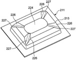
图9示出了实施方式3的壳体211。该实施方式3为实施方式2的变形例,隆起部213的上部面的中央区域224为无凹部的平面。其他的结构与实施方式2相同。FIG. 9 shows the case 211 of Embodiment 3. As shown in FIG. This Embodiment 3 is a modification of Embodiment 2, and the central region 224 of the upper surface of the raised portion 213 is a flat surface without a recessed portion. The other structures are the same as those of the second embodiment.

根据如此构成的实施方式3,与实施方式1、2同样,将收纳了帖片的施用器放置在皮肤上,当压住壳体的中央区域224或配置于壳体的中央区域224的指触部时,谷折部226以谷底227为中心凹进弯折(向下弯折,“谷折”),壳体的隆起部213向下方变形。由此,贴片朝向下方(皮肤)移动。此时,由于壳体由薄的片或膜形成,因此即使用较小的按压力,隆起部213也容易地向下方变形。另外,贴片在利用较小的力按压皮肤的同时垂直地推进得更深,其整体被相同的力按压向皮肤。另外,由于针垂直地侵入皮肤,因此穿刺时不会发生针弯曲、破损或折损的情况。According to Embodiment 3 thus constituted, as in Embodiments 1 and 2, when the applicator containing the patch is placed on the skin, the central area 224 of the casing or the finger touch disposed in the central area 224 of the casing is pressed. When the folded portion 226 is concavely folded with the valley bottom 227 as the center (downward folded, "valley folded"), the raised portion 213 of the housing is deformed downward. Thereby, the patch moves downward (skin). At this time, since the case is formed of a thin sheet or film, the raised portion 213 is easily deformed downward even with a small pressing force. In addition, the patch is pushed vertically deeper while pressing the skin with less force, and the entirety is pressed against the skin with the same force. In addition, since the needle penetrates the skin vertically, the needle does not bend, break or break during puncturing.

实施方式4:Embodiment 4:

图10示出了根据实施方式4的微针贴片施用器300,图11及图12示出了施用器用壳体301。FIG. 10 shows a microneedle patch applicator 300 according to Embodiment 4, and FIGS. 11 and 12 show a housing 301 for the applicator.

施用器300具有用于收纳下文中所述的微针贴片330的壳体301。Applicator 300 has a housing 301 for receiving a microneedle patch 330 described below.

壳体301例如通过对薄的树脂的片或膜进行成形(例如真空成形、气压成形、挤压成形),或者通过将经熔融的树脂注入到模具内的空腔来进行成形(例如注塑成形),并具有图示的外观形状。适用于壳体的成形的树脂为例如聚乙烯、聚丙烯、聚对苯二甲酸乙二醇酯、聚苯乙烯、尼龙、丙烯酸树脂、硅树脂、ABS。壳体的各部分的厚度可适当确定,使得当人用手指从上方按压壳体301时,产生将在下文中说明的所需的变形。例如,在由聚乙烯、聚丙烯、聚对苯二甲酸乙二醇酯形成的壳体的情况下,优选地,各部分的厚度为约50μm至1mm,更优选地,为100μm至500μm。The housing 301 is formed by, for example, forming a thin resin sheet or film (eg, vacuum forming, air-pressure forming, extrusion forming), or by injecting molten resin into a cavity in a mold (eg, injection molding) , and has the appearance shape shown in the figure. Suitable resins for the shaping of the housing are, for example, polyethylene, polypropylene, polyethylene terephthalate, polystyrene, nylon, acrylic, silicone, ABS. The thicknesses of the various parts of the casing may be appropriately determined so that when a person presses the casing 301 with a finger from above, a desired deformation as will be described later occurs. For example, in the case of a housing formed of polyethylene, polypropylene, polyethylene terephthalate, preferably, the thickness of each portion is about 50 μm to 1 mm, more preferably, 100 μm to 500 μm.

壳体301具有平坦的板状的外周基部302及被该外周基部302包围并从外周基部302向上方(图11的z轴方向)隆起的隆起部303。外周基部302由大致长方形的外缘304包围。隆起部303具有从上方观察时呈大致八边形的轮廓305。轮廓305具有在外周基部302的长边方向(图11的x轴方向)上延伸的一对长边方向轮廓部306、在短边方向(图11的y方向)上延伸的一对短边方向轮廓部307以及分别向长边方向与短边方向以规定的角度交叉的4个斜向轮廓部308。The case 301 has a flat plate-shaped outer peripheral base 302 and a raised portion 303 that is surrounded by the outer peripheral base 302 and protrudes upward (in the z-axis direction of FIG. 11 ) from the outer peripheral base 302 . The peripheral base 302 is surrounded by a generally rectangular outer edge 304 . The raised portion 303 has a substantially octagonal outline 305 when viewed from above. The outline 305 has a pair of long-side direction outline portions 306 extending in the long-side direction (the x-axis direction in FIG. 11 ) of the outer peripheral base 302 , and a pair of short-side directions extending in the short-side direction (the y-direction in FIG. 11 ) The contour portion 307 and the four oblique contour portions 308 intersecting at a predetermined angle in the long-side direction and the short-side direction, respectively.

隆起部303具有在中央呈火山口盆地状的平坦的凹部310及沿着凹部310的外周延伸并包围该凹部310的外轮山状的脊部311。凹部310的底部位于与外周基部302相比足够高的位置,在将壳体301放置在皮肤上的状态下,在凹部310的里面(如下文中说明,该里面成为支承微针贴片330(参照图13)的面)与皮肤之间确保充分的空间。The raised portion 303 has a flat concave portion 310 having a crater basin shape in the center, and an outer ring mountain-shaped ridge portion 311 extending along the outer periphery of the concave portion 310 and surrounding the concave portion 310 . The bottom of the concave portion 310 is located at a sufficiently high position compared to the peripheral base portion 302, and in the state where the housing 301 is placed on the skin, the inside of the concave portion 310 (as described later, the inside becomes the support microneedle patch 330 (refer to Sufficient space is ensured between the surface of Fig. 13) and the skin.

凹部310具有一对平行的长边方向缘和连接它们的端部的大致半圆弧的缘的跑道形状的轮廓。在实施方式中,凹部310在从长边方向的中央位置(x轴与y轴交叉的位置)向长边方向(x轴方向)隔开规定距离的位置形成有向短边方向笔直延伸的一对易变形部(谷折部)312。在本实施方式中,易变形部312以使该部分向上方弯曲的方式形成,相对于夹在易变形部312之间的中央区域313而位于中央区域313的两侧的端部区域314使易变形部312在中心易于向上方弯曲。The recessed part 310 has a racetrack-shaped outline of a pair of parallel long-side direction edges and edges of substantially semi-circular arcs connecting their ends. In the embodiment, the concave portion 310 is formed with a groove extending straight in the short-side direction at a position separated by a predetermined distance from the center position in the long-side direction (the position where the x-axis and the y-axis intersect) in the long-side direction (x-axis direction). To the easily deformable portion (valley fold portion) 312 . In the present embodiment, the easily deformable portion 312 is formed so that this portion is bent upward, and the end regions 314 located on both sides of the central region 313 with respect to the central region 313 sandwiched between the easily deformed portions 312 make it easier to The deformed portion 312 tends to be bent upward at the center.

在脊部311,呈放射状地形成有从脊部311的内侧向外侧横切脊部311的多个谷折部。在实施方式中,脊部311形成有12个谷折部315、316、317。12个谷折部315、316、317分别相对于穿过凹部310的中心的垂直轴(z轴)、长轴(x轴)及短轴(y轴)对称。例如,在各长边方向轮廓部306与相邻的两个斜向轮廓部308之间的边界形成有以随着从内侧朝向外侧谷折部之间的距离逐渐增加的方式呈放射状配置的两个第一谷折部315。在各短边方向轮廓部307与相邻的两个斜向轮廓部308之间的边界形成有以随着从内侧朝向外侧谷折部之间的距离逐渐增加的方式呈放射状配置的两个第二谷折部316。在各斜向的轮廓部308的中央形成有一个第三谷折部317。The ridge portion 311 is radially formed with a plurality of valley folds traversing the ridge portion 311 from the inner side to the outer side of the ridge portion 311 . In the embodiment, the ridge 311 is formed with 12 valley folds 315 , 316 , and 317 . The 12 valley folds 315 , 316 and 317 are respectively relative to the vertical axis (z axis) and the long axis passing through the center of the recess 310 . (x axis) and short axis (y axis) are symmetrical. For example, on the boundary between each longitudinal contour portion 306 and two adjacent oblique contour portions 308, two radially arranged two ridge portions are formed so as to gradually increase the distance between the valley folds from the inner side toward the outer side. a first valley fold 315 . On the boundary between each short-side direction contour portion 307 and the two adjacent oblique contour portions 308 , two radially-arranged second ridge portions are formed so as to gradually increase the distance between the valley folds from the inner side toward the outer side. Two valley folds 316 . A third valley fold 317 is formed in the center of each of the oblique contour portions 308 .

第一谷折部315的谷底318、第二谷折部316的谷底319以及第三谷折部317的谷底320为相对于外周基部302在水平方向上平行地延伸的水平谷底或向下方的外周基部倾斜的倾斜谷底。The valley bottom 318 of the first valley fold portion 315 , the valley bottom 319 of the second valley fold portion 316 , and the valley bottom 320 of the third valley fold portion 317 are horizontal valley bottoms extending parallel to the outer peripheral base 302 in the horizontal direction or a downward outer circumference. Inclined valley bottom with sloping base.

优选地,谷折部设置于当借助于指触部(按压部)322向无谷折部的壳体施加力时预想会在该无谷折部的壳体中产生变形的多个位置。由此,即使利用微小的力也能够使壳体变形为目标形状,因此可获得壳体的稳定的变形。Preferably, the valley folds are provided at positions where deformation is expected to occur in the valley-fold-free casing when force is applied to the valley-fold-free casing by means of the finger touch portion (pressing portion) 322 . As a result, the casing can be deformed into a target shape even by a slight force, so that stable deformation of the casing can be obtained.

优选地,谷折部呈促进壳体的变形的形状。为此,优选地,结合隆起部的形状等来改变谷底的角度、谷折部的形状或大小等。由此,即使利用微小的力也能够使壳体变形为目标形状,因此可获得壳体的稳定的变形。Preferably, the valley fold is in a shape that facilitates deformation of the housing. For this reason, it is preferable to change the angle of the valley bottom, the shape or size of the valley fold, and the like in combination with the shape of the protuberance and the like. As a result, the casing can be deformed into a target shape even by a slight force, so that stable deformation of the casing can be obtained.

如上所述,壳体311通过由薄的片或膜进行成形来形成,如图12所示,在隆起部303的背后形成有与隆起部303相应的形状的微针贴片收纳空间(凹部)321。另外,在凹部321的背面形成有贴片支承面331。贴片支承面331具有与凹部321的中央区域313及端部区域314的里侧相对应的中央区域340及端部区域341。如图13所示,贴片330配置于贴片支承面331,微针阵列344支承于中央区域340,双面胶350支承于两端部区域341。双面胶350可置换为粘结剂。As described above, the housing 311 is formed by molding a thin sheet or film. As shown in FIG. 12 , a microneedle patch storage space (recess) having a shape corresponding to the raised portion 303 is formed behind the raised portion 303 as shown in FIG. 12 . 321. In addition, a patch support surface 331 is formed on the back surface of the recessed portion 321 . The patch support surface 331 has a central area 340 and an end area 341 corresponding to the inner side of the central area 313 and the end area 314 of the recessed portion 321 . As shown in FIG. 13 , the patch 330 is arranged on the patch support surface 331 , the microneedle array 344 is supported on the central area 340 , and the double-sided tape 350 is supported on the end areas 341 . The double-sided tape 350 can be replaced with an adhesive.

此外,指触部322(参照图10)、微针贴片330(参照图13)、保护片355(参照图14)、防变形部件356(参照图15)的结构与实施方式1~3的相同。In addition, the structures of the finger contact portion 322 (see FIG. 10 ), the microneedle patch 330 (see FIG. 13 ), the protection sheet 355 (see FIG. 14 ), and the deformation preventing member 356 (see FIG. 15 ) are the same as those of the first to third embodiments. same.

根据如此构成的施用器300及壳体301,第三谷折部317的谷底320从内侧朝向外侧向斜下方延伸,因此壳体301针对朝向隆起部303的内侧的变形(这同时伴随向底座的垂直方向的变形)的阻力变小。因此,隆起部303在以其整体收缩的方式向内侧变形的同时使贴片330朝向皮肤垂直推进。其结果,贴片330相对于皮肤以较小的力垂直推进得更深,其整体被相同的力按压向皮肤。另外,由于针垂直地侵入皮肤,因此穿刺时不存在针弯曲、破损或折损的情况。According to the applicator 300 and the housing 301 thus constituted, the valley bottom 320 of the third valley fold 317 extends obliquely downward from the inner side toward the outer side, so that the housing 301 responds to the deformation toward the inner side of the raised portion 303 (this is accompanied by the deformation toward the base at the same time). deformation in the vertical direction) becomes smaller. Thus, the bulge 303 is deformed inwardly in such a way that its entire shrinkage causes the patch 330 to be pushed vertically toward the skin. As a result, the patch 330 is pushed further vertically with less force with respect to the skin, and the entirety thereof is pressed against the skin by the same force. In addition, since the needle penetrates the skin vertically, the needle does not bend, break or break during puncturing.

实施方式5:Embodiment 5:

图16示出了实施方式5的施用器的壳体501。在壳体501中,隆起部503从上方观察时呈大致略八边形,其轮廓505由长边方向的长边轮廓部506、短边方向的短边轮廓部507以及斜向的轮廓部508构成。在脊部511中,在与长边方向的长边轮廓部506、短边方向的短边轮廓部507以及斜向的轮廓部508的边界相应的各个位置形成有谷折部515、516。谷折部515的谷底朝向外周基部向下方倾斜。谷折部516的谷底也可以朝向外周基部向下方倾斜,或以平行于外周基部方式水平。FIG. 16 shows the housing 501 of the applicator of Embodiment 5. FIG. In the case 501 , the raised portion 503 has a substantially octagonal shape when viewed from above, and its outline 505 includes a long-side outline portion 506 in the longitudinal direction, a short-side outline portion 507 in the short-side direction, and an oblique outline portion 508 constitute. In the ridge portion 511 , valley folds 515 and 516 are formed at respective positions corresponding to the boundaries of the long-side contour portion 506 in the longitudinal direction, the short-side contour portion 507 in the short-side direction, and the oblique contour portion 508 . The valley bottom of the valley fold portion 515 is inclined downward toward the outer peripheral base. The valley bottom of the valley fold 516 may be inclined downward toward the outer peripheral base, or may be horizontal parallel to the outer peripheral base.

在如此构成的实施方式5中,谷折部515的谷底向与谷底正交的内侧方向移动并变形,因此凹部510与贴片的垂直推进性得以提高。因此,贴片相对于皮肤垂直推进,其整体被相同的力按压向皮肤。另外,由于针垂直地侵入皮肤,因此穿刺时不会发生针弯曲、破损或折损的情况。In Embodiment 5 thus constituted, the valley bottom of the valley fold 515 moves and deforms in the inner direction perpendicular to the valley bottom, so that the vertical pushability between the recessed portion 510 and the patch is improved. Thus, the patch is advanced vertically with respect to the skin, and its entirety is pressed against the skin by the same force. In addition, since the needle penetrates the skin vertically, the needle does not bend, break or break during puncturing.

实施方式6:Embodiment 6:

图17示出了实施方式6的施用器的壳体601。在壳体601中,隆起部603从上方观察时呈大致八边形,隆起部603的轮廓605由长边方向的长边轮廓部606、短边方向的短边轮廓部607以及斜向的轮廓部608构成,相邻的轮廓部605、606、607的边界部分形成有谷折部615、616。谷折部615、616的谷底从内侧朝向外侧向下方倾斜。FIG. 17 shows the housing 601 of the applicator of Embodiment 6. FIG. In the case 601, the raised portion 603 has a substantially octagonal shape when viewed from above, and the outline 605 of the raised portion 603 is composed of a long-side outline portion 606 in the long-side direction, a short-side outline portion 607 in the short-side direction, and an oblique outline. A portion 608 is formed, and valley fold portions 615 and 616 are formed at the boundary portions of the adjacent contour portions 605 , 606 and 607 . The valley bottoms of the valley folds 615 and 616 are inclined downward from the inner side toward the outer side.

在如此构成的实施方式6中,具有倾斜的谷底的谷折部615、616的下方的变形方向相对于包括凹部610的长轴的垂直面及包括短轴的垂直面相对称且朝向斜内侧,因此凹部610与支承于凹部610的背面的贴片相对于凹部610垂直推进。其结果,贴片相对于皮肤垂直且更有深度地推进,其整体被相同的力按压向皮肤。另外,由于针垂直地侵入皮肤,因此穿刺时不会发生针弯曲、破损或折损的情况。In Embodiment 6 thus constituted, since the deformation directions below the valley folds 615 and 616 having inclined valley bottoms are symmetrical with respect to the vertical plane including the long axis of the recessed portion 610 and the vertical plane including the short axis, and are directed obliquely inward, therefore The concave portion 610 and the patch supported on the back surface of the concave portion 610 are pushed vertically relative to the concave portion 610 . As a result, the patch is advanced perpendicularly and deeper to the skin, and the whole is pressed against the skin by the same force. In addition, since the needle penetrates the skin vertically, the needle does not bend, break or break during puncturing.

在本实施方式中,位于长边方向轮廓部606的两侧的谷折部615的谷底的倾斜角可以与位于短边方向轮廓部607的两侧的谷折部616的谷底的倾斜角相同,也可以为任一方大于另一方。In this embodiment, the inclination angle of the valley bottoms of the valley folds 615 located on both sides of the long-side direction contour portion 606 may be the same as the inclination angle of the valley bottoms of the valley folds 616 located on both sides of the short-side direction contour portion 607 , Either one is greater than the other.

实施方式7:Embodiment 7:

在实施方式6中,所有的谷折部的谷底从隆起部的内侧朝向外侧向下方倾斜,但如图18所示,也可以使所有的谷折部715、716的谷底以与外周基部平行的方式朝向水平方向,也可以使谷折部715或718的一方倾斜而使另一方朝向水平。In Embodiment 6, the valley bottoms of all the valley folds are inclined downward from the inner side toward the outer side of the raised portion, but as shown in FIG. It is also possible to incline one of the valley folds 715 or 718 and make the other face horizontal.

实施方式8:Embodiment 8:

在以上的实施方式中,壳体的隆起部的轮廓设定为多边形,但如图19所示,还可以使隆起部803的轮廓呈圆形。在本实施方式中,在壳体801的隆起部803中,可以等间隔地在圆周方向上配置从凹部810的中心向放射方向延伸的多个谷折部811,还能够以旋转对称的方式以穿过隆起部的中心的垂直轴为中心配置多个谷折部。优选地,在本实施方式8的壳体中,也与所述的实施方式同样,在凹部810平行地设置至少两个易变形部812。In the above embodiment, the outline of the raised portion of the housing is set to be polygonal, but as shown in FIG. 19 , the outline of the raised portion 803 may be circular. In the present embodiment, in the protruding portion 803 of the housing 801, a plurality of valley folds 811 extending in the radial direction from the center of the recessed portion 810 may be arranged at equal intervals in the circumferential direction, and may also be rotationally symmetrical. A plurality of valley folds are arranged around a vertical axis passing through the center of the raised portion. Preferably, in the case of the eighth embodiment, as in the above-described embodiment, at least two easily deformable portions 812 are provided in parallel to the recessed portion 810 .

变形例:Variation:

在以上的实施方式中,壳体隆起部的平面形状无限定,可以为四边形、五边形、六边形等的多边形,还可以为圆形或楕圆形或者跑道形状。在任意实施方式中,优选地,谷底倾斜的谷折部及具有倾斜的谷底的谷折部相对于包括隆起部的长轴或短轴的垂直面对称。另外优选地,在具有五边形等的奇数个的边的多边形的情况下,具有倾斜的谷底的谷折部以等间隔的方式配置于以垂直轴为中心的圆周方向上。此外,对于圆形隆起部无法区别长轴与短轴,但谷底倾斜的谷折部可以配置为相对于与中心轴(上下方向的轴Z)正交的两个轴(正交的水平轴X、Y)的至少一个对称,还可以配置为相对于中心轴中心对称。In the above embodiments, the planar shape of the raised portion of the housing is not limited, and may be a polygon such as a quadrangle, a pentagon, or a hexagon, or may be a circle, an elliptical circle, or a racetrack shape. In any embodiment, preferably, the valley folds with the sloped valley bottoms and the valley folds with the sloped valley bottoms are symmetrical with respect to a vertical plane including the long axis or the short axis of the bulge. Furthermore, in the case of a polygon having an odd number of sides such as a pentagon, it is preferable that valley folds having inclined valley bottoms are arranged at equal intervals in the circumferential direction centered on the vertical axis. In addition, the long axis and the short axis cannot be distinguished for the circular ridges, but the valley folds whose valley bottoms are inclined can be arranged with respect to two axes (orthogonal horizontal axis X) orthogonal to the central axis (axis Z in the vertical direction). At least one symmetry of , Y) can also be configured to be centrally symmetric with respect to the central axis.

同样,凹部及相应的指触部的形状也不限于跑道形状,还可以为楕圆形、圆形、四边形及其他多边形的一种。Likewise, the shape of the concave portion and the corresponding finger contact portion is not limited to the shape of a racetrack, and can also be one of an elliptical circle, a circle, a quadrangle and other polygons.

脊部无需在凹部的周边连续地配置,也可以不连续地配置。The ridges do not need to be continuously arranged around the recesses, and may be arranged discontinuously.

在以上的说明中,借助于指触部来将贴片按压向皮肤,但也可以不使用指触部而直接用手指按压凹部。In the above description, the patch is pressed against the skin by means of the finger touch portion, but the concave portion may be directly pressed with a finger without using the finger touch portion.

隆起部的凹部不是必须的,隆起部的顶上部还可以为无凹部的平坦的面。在这种情况下,谷折部形成于隆起部的外周部。谷折部的数量与谷底的倾斜角以确保针的垂直穿刺性的方式适当选择。The concave portion of the protuberance is not essential, and the top portion of the protuberance may be a flat surface without concave portions. In this case, the valley fold portion is formed on the outer peripheral portion of the raised portion. The number of valley folds and the inclination angle of the valley bottom are appropriately selected in such a way as to ensure the vertical penetrability of the needle.

就指触部而言,在上部件中无需与下部件的凸台相对应地设置贯通孔,也可以在上部件32中与下部件33的凸台35对置的位置形成薄壁部851,当向指触部施加了所需的力时,凸台35使该薄壁部851变形或损坏。在这种情况下,薄壁部851用作向操作人员通知向指触部施加了规定的按压力的情况的指示器。As for the finger contact portion, it is not necessary to provide through holes in the upper member corresponding to the bosses of the lower member, and the thin-walled portion 851 may be formed at the position of the upper member 32 facing the bosses 35 of the lower member 33, The boss 35 deforms or damages the thin-walled portion 851 when a desired force is applied to the finger contact portion. In this case, the thin-walled portion 851 serves as an indicator for notifying the operator that a predetermined pressing force has been applied to the finger touch portion.

用于将向指触部施加了规定的按压力的情况通知操作人员的指示器可以为例如当向指触部施加了规定的按压力时,分别在上部件与下部件形成的特定的形状部分彼此接触或分离,或者为设置于上部件与下部件中任意一方的特定的形状部分被破坏,发出声音(接触音、破坏音)的结构。具体而言,可以构成为在上部件或下部件的一方设置孔等,并在另一方设置与此卡扣接触的突起,通过它们的相互嵌合来获得锁定感或发出声音。或者,也可以构成为朝向下方成为略微凸状的曲面,构成为由作为圆形板的穹顶形弹簧等金属或树脂产生变形,所述圆形板被构成为例如将从上方向下方按压圆形板部的中央部时朝向上方的凸状的曲面反转为凹状曲面,并在此时发出声音或振动。The indicator for notifying the operator that a predetermined pressing force has been applied to the finger touch portion may be, for example, a specific shape portion formed on the upper member and the lower member, respectively, when the predetermined pressing force is applied to the finger touch portion. Contact or separation, or a specific shape part provided on either the upper member or the lower member is broken, and a sound (contact sound, breaking sound) is generated. Specifically, a hole or the like may be provided on one of the upper member or the lower member, and protrusions that are in contact with the snaps may be provided on the other, and a locking feeling or sound may be obtained by mutual engagement. Alternatively, it may be configured to have a slightly convex curved surface toward the downward direction, and may be configured to be deformed by metal or resin such as a dome-shaped spring as a circular plate that presses a circular shape from upper to lower, for example. The convex curved surface facing upward in the central portion of the plate portion is reversed to a concave curved surface, and at this time, sound or vibration is generated.

实施方式9:Embodiment 9:

图21示出了实施方式9的施用器1000。施用器1000具有壳体1001及按压机构1015。FIG. 21 shows the applicator 1000 of Embodiment 9. FIG. The applicator 1000 has a housing 1001 and a pressing mechanism 1015 .

如图22所示,与如上所述的实施方式同样,壳体1001具有外周基部1002。在外周基部1002的长边方向缘部1011形成有例如括号状的切口1012。在外周基部1002的短边方向缘部1013形成有例如拱形的切口1014。除了以上的几点之外,壳体1001与实施方式4的壳体301实质上相同。因此,对于壳体1001省略其详细的说明。此外,在以下的说明中,对壳体1001的各部分适当地使用900号段的附图标记,该900号段的附图标记是将对实施方式4的壳体的相应的部分所赋予的附图标记加上600而得的。As shown in FIG. 22 , the case 1001 has an outer peripheral base 1002 as in the above-described embodiment. For example, a bracket-shaped cutout 1012 is formed in the edge portion 1011 in the longitudinal direction of the outer peripheral base portion 1002 . An arch-shaped cutout 1014 is formed in the short-side direction edge portion 1013 of the outer peripheral base portion 1002, for example. Except for the above points, the case 1001 is substantially the same as the case 301 of the fourth embodiment. Therefore, the detailed description of the case 1001 is omitted. In addition, in the following description, reference numerals in paragraph 900 are appropriately used for the respective parts of the casing 1001, and the numerals in paragraph 900 are assigned to the corresponding parts of the casing according to the fourth embodiment. Reference numerals are obtained by adding 600.

按压机构1015大体上具有上部结构1016和下部结构1017。上部结构1016具有呈大致倒“U”字形状或大致倒拱形的弹性拉伸部1018。弹性拉伸部1018由例如具有弹性的合成树脂形成。因此,当从弹性拉伸部1018的中央部的上方向弹性拉伸部1018的中央部施加力时,弹性拉伸部1018的两端部1019能够以相互远离的同时向外侧移动的方式变形。在实施方式中,弹性拉伸部1018的两端部1019形成为大致圆筒形状。在自由状态下,左右两端部1019的间隔与形成于壳体1001的长边方向缘部1011的一对括号状切口1012的距离相同或稍大。The pressing mechanism 1015 generally has an upper structure 1016 and a lower structure 1017 . The upper structure 1016 has a substantially inverted "U" shape or a substantially inverted arched elastic stretch portion 1018 . The elastic stretching portion 1018 is formed of, for example, a synthetic resin having elasticity. Therefore, when a force is applied to the central portion of the elastically stretchable portion 1018 from above the central portion of the elastically stretched portion 1018 , the both ends 1019 of the elastically stretched portion 1018 can be deformed so as to move outward while moving away from each other. In the embodiment, both ends 1019 of the elastic stretching portion 1018 are formed in a substantially cylindrical shape. In the free state, the distance between the left and right end portions 1019 is the same as or slightly larger than the distance between the pair of bracket-shaped notches 1012 formed in the longitudinal edge portion 1011 of the casing 1001 .

在弹性拉伸部1018的中央区域中形成有贯通上部面与下部面的大致四边形的开口1020。在弹性拉伸部1018的上部面形成有从与开口1020斜向对置的角部朝向两端部1019向外侧笔直延伸的一对槽1021。A substantially quadrangular opening 1020 penetrating the upper surface and the lower surface is formed in the central region of the elastic stretching portion 1018 . A pair of grooves 1021 are formed on the upper surface of the elastic stretching portion 1018 and extend straight outward from the corners that are diagonally opposed to the opening 1020 toward the both ends 1019 .

如图23所示,开口1020与槽1021中收纳有扭转弹簧1022。扭转弹簧1022具有卷绕了线材的卷绕部分1023和从该卷绕部分1023的两端笔直延伸的一对臂部分1024。如此构成的扭转弹簧1022的卷绕部分1023收纳于开口1020,臂部分1024收纳于槽1021,借助于销1025来保持在弹性拉伸部1018。销1025与弹性拉伸部1018的中央下部面卡合,由此,在将扭转弹簧1022的臂从图23的(b)部分中以实线表示的位置缩回以虚线表示的位置的状态下,卷绕部分1023保持在开口1020,借助于臂部分1024,弹性拉伸部1018以其两端部1019相互靠近的方式被赋能。As shown in FIG. 23 , a torsion spring 1022 is accommodated in the opening 1020 and the groove 1021 . The torsion spring 1022 has a winding portion 1023 around which the wire is wound, and a pair of arm portions 1024 extending straight from both ends of the winding portion 1023 . The winding portion 1023 of the torsion spring 1022 thus constituted is accommodated in the opening 1020 , the arm portion 1024 is accommodated in the groove 1021 , and is held in the elastic tension portion 1018 by the pin 1025 . The pin 1025 is engaged with the central lower surface of the elastic stretching portion 1018, whereby the arm of the torsion spring 1022 is retracted from the position shown by the solid line in the part (b) of FIG. 23 to the position shown by the broken line , the winding portion 1023 is held at the opening 1020, and by means of the arm portion 1024, the elastic stretching portion 1018 is energized in such a manner that its two end portions 1019 are close to each other.

在实施方式中,为了将销1025定位,在弹性拉伸部1018的下部面中央形成有宽度方向的槽1026,销1025收纳于该槽1026。In the embodiment, in order to position the pin 1025, a groove 1026 in the width direction is formed in the center of the lower surface of the elastic stretching portion 1018, and the pin 1025 is accommodated in the groove 1026.

指触部1027组装于弹性拉伸部1018。指触部1027具有用户按压手指(例如拇指)的上部1028和从上部1028的下部面向下方延伸的一对脚部1029。各脚部1029在其下端部具有卡合部1030。如此构成的指触部1027使扭转弹簧1022卷绕部分1023位于脚部1029之间,并使脚部1029在开口1020中从开口1020的上方向下方插通,并组装于弹性拉伸部1018。The finger contact portion 1027 is assembled to the elastic stretching portion 1018 . The finger touch portion 1027 has an upper portion 1028 where the user presses a finger (eg, a thumb) and a pair of foot portions 1029 extending downward from the lower portion of the upper portion 1028 . Each leg portion 1029 has an engaging portion 1030 at its lower end. The finger contact portion 1027 constructed in this way has the winding portion 1023 of the torsion spring 1022 positioned between the leg portions 1029 , and the leg portions 1029 are inserted through the opening 1020 from above to the bottom of the opening 1020 , and are assembled to the elastic stretching portion 1018 .

连接部件1031卡合并保持于从开口1020向下方突出的脚部1029的下端卡合部1030。连接部件1031为大致圆形的部件,在上部面的对称位置形成有与下端卡合部1030相应的形状的被卡合部1032,将脚部1029的下端卡合部1030插入被卡合部1032中并卡合,指触部1027与连接部件1031相连接。The connecting member 1031 is engaged with and held by the lower end engaging portion 1030 of the leg portion 1029 protruding downward from the opening 1020 . The connecting member 1031 is a substantially circular member, and an engaged portion 1032 having a shape corresponding to the lower end engaging portion 1030 is formed at a symmetrical position on the upper surface, and the lower end engaging portion 1030 of the leg portion 1029 is inserted into the engaged portion 1032 The finger contact portion 1027 is connected with the connecting member 1031 when it is in the middle and snapped together.

如图24所示,下部结构1017由上部件1033及下部件1034构成。当从上方观察时,上部件1033及下部件1034,尤其是下部件1034,呈与壳体1001的凹部910大致相同的大小的跑道形状。在上部件1033的下部面,在长边方向的两端部形成有向下方突出的台部1035。各台部1035在其长边方向两端侧形成有向宽度方向延伸的爪部1036,在其中央缘部形成有向下方突出的突起1037。上部件1033的下部面中央形成有圆柱凸台1038。圆柱凸台1038的下端部1039具有比圆柱凸台1038的下端部1039以外的部分稍大的直径。另外,在圆柱凸台1038沿着中心轴从下端面朝向上方形成有向上部件1033的长边方向及短边方向延伸的纵向十字槽1040,当从周边向下端部1039施力时,能够以纵向十字槽1040的外径变小的方式变形。As shown in FIG. 24 , the lower structure 1017 is composed of an upper member 1033 and a lower member 1034 . When viewed from above, the upper member 1033 and the lower member 1034 , especially the lower member 1034 , have a racetrack shape having substantially the same size as the recessed portion 910 of the housing 1001 . On the lower surface of the upper member 1033, at both ends in the longitudinal direction, there are formed base portions 1035 that protrude downward. Each platform portion 1035 is formed with claw portions 1036 extending in the width direction on both end sides in the longitudinal direction, and a protrusion 1037 protruding downward is formed on the central edge portion thereof. A cylindrical boss 1038 is formed in the center of the lower surface of the upper member 1033 . The lower end portion 1039 of the cylindrical boss 1038 has a slightly larger diameter than the portion other than the lower end portion 1039 of the cylindrical boss 1038 . In addition, longitudinal cross grooves 1040 extending in the longitudinal direction and the short side direction of the upward member 1033 are formed on the cylindrical boss 1038 along the central axis from the lower end face upward. The longitudinal cross groove 1040 is deformed so that the outer diameter becomes smaller.

下部件1034的整体由中央板部1041及从该中央板部1041的两端朝向斜上方延伸的倾斜板部1042形成。在中央板部1041的中央形成有贯通中央板部1041的上部面与下部面的贯通孔1043。贯通孔1043的内面上端部形成有环状隆起部(突条)1045。贯通孔1043的除了环状隆起部1045的内径大致与圆柱凸台大径下端部1039的外径相等,环状隆起部1045的内径稍小于圆柱凸台大径下端部1039的外径。The entire lower member 1034 is formed by a central plate portion 1041 and inclined plate portions 1042 extending obliquely upward from both ends of the central plate portion 1041 . A through hole 1043 penetrating the upper surface and the lower surface of the center plate portion 1041 is formed in the center of the center plate portion 1041 . An annular raised portion (protrusion) 1045 is formed at the end portion of the inner surface of the through hole 1043 . The inner diameter of the through hole 1043 is approximately equal to the outer diameter of the cylindrical boss large-diameter lower end 1039 except for the annular raised portion 1045 , which is slightly smaller than the outer diameter of the cylindrical boss large-diameter lower end 1039 .

虽然未图示,但在中央板部1041可形成有在贯通孔1043的周边以包围该贯通孔1043的方式配置的多个扇形槽,在这种情况下,圆柱凸台1038中也可以不形成有上述纵向十字槽1040。Although not shown, the center plate portion 1041 may be formed with a plurality of fan-shaped grooves arranged around the through-hole 1043 so as to surround the through-hole 1043 . In this case, the cylindrical boss 1038 may not be formed. There are longitudinal cross grooves 1040 as described above.

在下部件1034的倾斜板部1042的上部面两端侧形成有与上部件1033的爪部1036相应的形状的卡合槽1047,在将上部件1033放置于下部件1034上的状态下,上部件1033的爪部1036卡合于下部件1034的卡合槽1047并保持下部件1034。Engagement grooves 1047 of shapes corresponding to the claw portions 1036 of the upper member 1033 are formed on both end sides of the upper surface of the inclined plate portion 1042 of the lower member 1034. In the state where the upper member 1033 is placed on the lower member 1034, the upper member The claws 1036 of the 1033 are engaged with the engaging grooves 1047 of the lower member 1034 to hold the lower member 1034 .

下部件1034的倾斜板部1042的端部在其中央形成有长度方向的切口1048,在将上部件1033放置于下部件1034上的状态下,上部件1033的突起1037卡合于下部件1034的凹部1048,来限制对上部件1033相对于下部件1034在宽度方向上的移动。The end portion of the inclined plate portion 1042 of the lower member 1034 is formed with a longitudinal notch 1048 in the center thereof. When the upper member 1033 is placed on the lower member 1034, the protrusions 1037 of the upper member 1033 are engaged with the protrusions of the lower member 1034. The concave portion 1048 restricts the movement of the upper member 1033 relative to the lower member 1034 in the width direction.

如图21~图23所示,如此构成的按压机构1015组装在壳体1001中。具体而言,下部结构1017配置于壳体1001的中央凹部910。使上部结构1016的弹性拉伸部1018的两端部1019与壳体1001的长边方向切口1012卡合,在这些两端部1019之间保持壳体1001。此时,用户在用拇指与食指抵接壳体1001的切口1014来保持壳体1001的同时,使上部结构1016与壳体1001组合。As shown in FIGS. 21 to 23 , the pressing mechanism 1015 thus constructed is assembled in the casing 1001 . Specifically, the lower structure 1017 is arranged in the central concave portion 910 of the casing 1001 . Both ends 1019 of the elastically stretched portion 1018 of the upper structure 1016 are engaged with the longitudinal notch 1012 of the casing 1001 , and the casing 1001 is held between the both ends 1019 . At this time, the user combines the upper structure 1016 with the casing 1001 while holding the casing 1001 with the thumb and the index finger abutting against the cutout 1014 of the casing 1001 .

借助于扭转弹簧1022,弹性拉伸部1018的两端部1019被向对置的方向赋能,因此壳体1001被稳定支承在两端部1019之间。如图所示,在组上部结构1016与下部结构1017组合的状态下,连接部件1031的下部面与指触部1027的上部面相接,壳体1001被相对于按压机构1015稳定支承。By the torsion spring 1022 , both end portions 1019 of the elastic stretching portion 1018 are energized in the opposing directions, so that the housing 1001 is stably supported between the end portions 1019 . As shown in the figure, the lower surface of the connecting member 1031 is in contact with the upper surface of the finger contact portion 1027 in a state where the stack upper structure 1016 and the lower structure 1017 are combined, and the housing 1001 is stably supported by the pressing mechanism 1015 .

如上所述,当贴附微针贴片时,剥离贴附于壳体1011的底面的保护片,露出贴片。接下来,将施用器1000放置在皮肤上,使壳体1011的外周基部与皮肤相接触。此时,弹性拉伸部1018的两端部1019与皮肤相接。As described above, when the microneedle patch is attached, the protective sheet attached to the bottom surface of the housing 1011 is peeled off to expose the patch. Next, the applicator 1000 is placed on the skin with the peripheral base of the housing 1011 in contact with the skin. At this time, both ends 1019 of the elastic stretching portion 1018 are in contact with the skin.

接着,在用手指(例如拇指)抵接按压机构1015的指触部1027的同时,朝向皮肤按压。由此,弹性拉伸部1018在其中央部向下方移动的同时,在两端部1019与皮肤相接触的状态下向外侧移动。其结果,微针贴片所对置的区域的皮肤向彼此相反的方向拉伸。因此,张力施加于皮肤,之后微针易于刺入皮肤。即,皮肤被拉伸,对于来自相对于皮肤表面垂直的方向的压力产生阻力,从而处于能够发生一定的应力的状态。当向这种状态的皮肤表面按压微针前端时,能够可靠地向皮肤表面穿刺微针。两端部1019可以形成增加与皮肤之间的摩擦等的凸凹或槽,还可以设置粘结剂等。Next, the finger (for example, the thumb) is pressed toward the skin while abutting the finger contact portion 1027 of the pressing mechanism 1015 . As a result, the elastic stretching portion 1018 moves outward in a state in which both end portions 1019 are in contact with the skin while the center portion thereof moves downward. As a result, the skin in the area where the microneedle patch faces is stretched in opposite directions. Thus, tension is applied to the skin, after which the microneedles tend to penetrate the skin. That is, the skin is stretched to generate resistance to pressure from a direction perpendicular to the surface of the skin, so that a certain amount of stress can be generated. When the tip of the microneedle is pressed against the skin surface in this state, the microneedle can be reliably punctured on the skin surface. Both end portions 1019 may be formed with projections and depressions or grooves to increase friction with the skin or the like, and may also be provided with an adhesive or the like.

随着指触部1027朝向皮肤推进,下部结构1017在按压壳体1011的凹部中央区域913的同时,使壳体1011变形。若壳体1011的变形加剧,下部件1034的倾斜板部1042分别与凹部端部区域相接触,支承在凹部中央区域的微针被强力按压向皮肤。The lower structure 1017 deforms the housing 1011 while pressing the recessed central region 913 of the housing 1011 as the finger touch portion 1027 is advanced toward the skin. When the deformation of the housing 1011 increases, the inclined plate portions 1042 of the lower member 1034 respectively come into contact with the end regions of the concave portion, and the microneedles supported in the central region of the concave portion are strongly pressed against the skin.

当向指触部1027施力时,下部结构1017中的上部件1033的中央部相对于其两侧部分向下方弯曲规定量,或者下部件1034的中央部相对于其两侧部分相对地向上方弯曲规定量,或者上部件1033及下部件1034的中央部分别向下方及上方弯曲规定量,其结果,上部件1033的圆柱凸台1038进入下部件1034的贯通孔1043。当向指触部1027施加预先确定的规定的力时,圆柱凸台1038的下端部1039越过下部件1034的隆起部1045,圆柱凸台1038的下端部1039与贯通孔内面的隆起部(突条)1045卡合。下端部1039与隆起部1045的卡合通过与指触部1027相接触的手指的触感或声音来使用户感知到。因此,用户可认识到对指触部1027施加了规定的力。另外,通过向指触部1027施加规定的力,微针贴片的针以规定量侵入皮肤。其结果,载置于针中的药剂被可靠地向皮肤给送。像这样,圆柱凸台下端部1039及与之相应的隆起部1045用作使用户感知指触部1027施加了规定的力的情况的指示器。When force is applied to the finger contact portion 1027, the central portion of the upper member 1033 in the lower structure 1017 is bent downward by a predetermined amount relative to the both sides thereof, or the central portion of the lower member 1034 is relatively upward relative to the both sides thereof. The upper member 1033 and the lower member 1034 are bent by a predetermined amount, or the central portions of the upper member 1033 and the lower member 1034 are respectively bent downward and upward by a predetermined amount. When a predetermined force is applied to the finger contact portion 1027, the lower end portion 1039 of the cylindrical boss 1038 gets over the protruding portion 1045 of the lower member 1034, and the lower end portion 1039 of the cylindrical boss 1038 and the protruding portion (projection bar) on the inner surface of the through hole. )1045 snapped. The engagement between the lower end portion 1039 and the protruding portion 1045 is perceived by the user through the touch or sound of the finger in contact with the finger touch portion 1027 . Therefore, the user can recognize that a predetermined force is applied to the finger touch portion 1027 . In addition, by applying a predetermined force to the finger touch portion 1027, the needles of the microneedle patch penetrate the skin by a predetermined amount. As a result, the medicine placed on the needle is reliably delivered to the skin. In this way, the lower end portion 1039 of the cylindrical boss and the corresponding raised portion 1045 serve as an indicator for the user to perceive that a predetermined force has been applied by the finger touch portion 1027 .

当施加于指触部1027的力减弱并小于规定的力时,借助于上部件1033及下部件1034的弹性恢复力,圆柱凸台1038的下端部1039从贯通孔内面的隆起部(突条)1045脱离。下端部1039与隆起部1045的卡合脱离的情况通过放置在指触部1027上的手指而被用户感知。由此,用户认识到未向指触部1027持续施加规定的力。此外,通过使用户预先认识到将圆柱凸台1038的下端部1039与贯通孔内面的隆起部(突条)1045卡合的状态保持规定时间,能够可靠地将所需量的药剂向皮肤给送。通过将该规定时间记载于例如施用器1000的使用说明书等,能够将规定量的药剂可靠地向皮肤给送。When the force applied to the finger contact portion 1027 is weakened and becomes smaller than a predetermined force, the lower end portion 1039 of the cylindrical boss 1038 is removed from the protruding portion (protrusion) on the inner surface of the through hole by the elastic restoring force of the upper member 1033 and the lower member 1034. 1045 break away. The engagement and disengagement of the lower end portion 1039 and the protruding portion 1045 is sensed by the user by the finger placed on the finger touch portion 1027 . Thereby, the user recognizes that the predetermined force is not being continuously applied to the finger touch portion 1027 . In addition, by making the user recognize in advance that the state where the lower end 1039 of the cylindrical boss 1038 is engaged with the raised portion (protrusion) 1045 on the inner surface of the through hole is maintained for a predetermined period of time, it is possible to reliably deliver a desired amount of medicine to the skin . By describing the predetermined time in the instruction manual of the applicator 1000 or the like, for example, a predetermined amount of the drug can be reliably delivered to the skin.

当释放施加于指触部1027的力时,弹性拉伸部1018及壳体1011通过它们自身的弹性而恢复至变形前的形状。When the force applied to the finger contact portion 1027 is released, the elastic stretching portion 1018 and the housing 1011 are restored to their pre-deformed shapes by their own elasticity.

此外,按压机构1015与壳体1001还可以在使用前由用户卡合。或者,无需卡合,而通过利用弹性拉伸部1018的两端部1019与壳体1001的长边方向切口1012或通过目测来确定位置,从而在用于皮肤上等时进行定位。In addition, the pressing mechanism 1015 and the housing 1001 can also be engaged by the user before use. Alternatively, it is not necessary to engage, but the position is determined by using the both ends 1019 of the elastic stretching portion 1018 and the longitudinal notch 1012 of the casing 1001 or by visual inspection, so as to be positioned when used on the skin or the like.

实施方式10:Embodiment 10:

图25(图25的(a)部分、(b)部分)示出了实施方式10的施用器1100。在施用器1100中,按压机构1015中的上部结构1016的连接部件1031中形成有用于将该连接部件1031与下部结构1017相连接的连接结构1051。在实施方式中,连接结构1051具有相对于连接部件1031的上下方向中心轴对称的一对卡合爪1052。卡合爪1052的间隔被设计为与按压机构1015中的下部结构的上部件1033的短片方向宽度大致相等,借助于卡合爪1052,下部结构1017的整体保持于上部结构1016。其他结构与实施方式9实质上相同。因此,对于相同部件或相同部分赋予相同的附图标记并省略说明。FIG. 25 (parts (a), (b) of FIG. 25 ) shows the applicator 1100 of Embodiment 10. FIG. In the applicator 1100, a connection structure 1051 for connecting the connection part 1031 to the lower structure 1017 is formed in the connection part 1031 of the upper structure 1016 in the pressing mechanism 1015. In the embodiment, the connection structure 1051 has a pair of engaging claws 1052 symmetrical with respect to the central axis of the connection member 1031 in the vertical direction. The interval between the engaging claws 1052 is designed to be approximately equal to the width in the short direction of the upper member 1033 of the lower structure in the pressing mechanism 1015 . The other structures are substantially the same as those in the ninth embodiment. Therefore, the same reference numerals are assigned to the same members or the same parts, and descriptions thereof are omitted.

根据如此构成的实施方式10的施用器1100,在使按压机构1015的上部结构1016与下部结构1017一体化的状态下,能够将该按压机构1015容易地组装于壳体1001。According to the applicator 1100 of the tenth embodiment thus configured, the pressing mechanism 1015 can be easily assembled to the housing 1001 in a state in which the upper structure 1016 and the lower structure 1017 of the pressing mechanism 1015 are integrated.

实施方式11:Embodiment 11:

图26、27示出了实施方式11的施用器1200。施用器1200具有壳体1201及按压机构1215。26, 27 illustrate the applicator 1200 of the eleventh embodiment. The applicator 1200 has a housing 1201 and a pressing mechanism 1215 .

如图27所示,与所述的实施方式9同样,壳体1201具有外周基部1202。外周基部1202的长边方向缘部1211中形成有例如括号状的切口1212。除了这一点外,壳体1201与实施方式4的壳体301实质上相同。因此,对于壳体1201,省略其详细说明。此外,在以下的说明中,对壳体1201的各部分适当地使用900号段附图标记,该900号段附图标记是将对实施方式4的壳体相应的部分所赋予的附图标记加上600而得的。As shown in FIG. 27 , like the ninth embodiment described above, the case 1201 has an outer peripheral base 1202 . For example, a bracket-shaped cutout 1212 is formed in the longitudinal edge portion 1211 of the outer peripheral base portion 1202 . Except for this point, the casing 1201 is substantially the same as the casing 301 in the fourth embodiment. Therefore, the detailed description of the case 1201 is omitted. In addition, in the following description, reference numerals in paragraph 900 are appropriately used for the respective parts of the casing 1201, and the numerals in paragraph 900 are reference numerals assigned to the corresponding parts of the casing according to the fourth embodiment. Plus 600.

按压机构1215大体上具有上部结构1216和下部结构1217。The pressing mechanism 1215 generally has an upper structure 1216 and a lower structure 1217 .

上部结构1216具有呈大致倒“U”字形状或大致倒拱形的弹性拉伸部1218。弹性拉伸部1218由例如具有弹性的合成树脂形成。因此,当从弹性拉伸部1218的中央部的上方向弹性拉伸部1218的中央部施力时,弹性拉伸部1218的两端部1219能够以相互远离的同时向外侧移动的方式变形。在实施方式中,弹性拉伸部1218的两端部1219形成为大致圆筒形状。在自由状态下,左右两端部1219的间隔与形成于壳体1201的长边方向缘部1211的一对括号状切口1212的距离相同或稍大。The upper structure 1216 has a substantially inverted "U" shape or a substantially inverted arched elastic stretch portion 1218 . The elastic stretching portion 1218 is formed of, for example, a synthetic resin having elasticity. Therefore, when a force is applied to the central portion of the elastically stretchable portion 1218 from above the central portion of the elastically stretchable portion 1218, the both ends 1219 of the elastically stretchable portion 1218 can be deformed so as to move outward while moving away from each other. In the embodiment, both ends 1219 of the elastic stretching portion 1218 are formed in a substantially cylindrical shape. In the free state, the distance between the left and right end portions 1219 is the same as or slightly larger than the distance between the pair of bracket-shaped notches 1212 formed in the longitudinal edge portion 1211 of the casing 1201 .

在弹性拉伸部1218的中央区域中形成有贯通上部面与下部面的大致四边形的开口1220。在弹性拉伸部1218的上部面形成有从与开口1220的斜向对置的角部朝向两端部1219向外侧笔直延伸的一对槽1221。A substantially quadrangular opening 1220 penetrating the upper surface and the lower surface is formed in the central region of the elastic stretching portion 1218 . A pair of grooves 1221 are formed on the upper surface of the elastic stretching portion 1218 and extend straight outward from the corners of the opening 1220 which are diagonally opposed to the both ends 1219 .

扭转弹簧1222可收纳于开口1220与槽1221中。扭转弹簧1222具有卷绕了线材的卷绕部分1223和从该卷绕部分1223的两端笔直延伸的一对臂部分1224。如此构成的扭转弹簧1222的卷绕部分1223收纳于开口1220,臂部分1224收纳于槽1221,借助于销1225来保持在弹性拉伸部1218。销1225与弹性拉伸部1218的中央下部面卡合,由此,在缩小了扭转弹簧1222的臂展开角度的状态下,卷绕部分1223保持在开口1220,借助于臂部分1224,弹性拉伸部1218以其两端部1219相互靠近的方式被赋能。The torsion spring 1222 can be received in the opening 1220 and the groove 1221 . The torsion spring 1222 has a winding portion 1223 around which the wire is wound, and a pair of arm portions 1224 extending straight from both ends of the winding portion 1223 . The winding portion 1223 of the torsion spring 1222 thus constituted is accommodated in the opening 1220 , the arm portion 1224 is accommodated in the groove 1221 , and is held in the elastic tension portion 1218 by the pin 1225 . The pin 1225 is engaged with the lower center surface of the elastic stretching portion 1218, whereby the winding portion 1223 is held at the opening 1220 in a state in which the arm deployment angle of the torsion spring 1222 is reduced, and the arm portion 1224 is elastically stretched. The portion 1218 is energized such that its two end portions 1219 are close to each other.

在实施方式中,为了将销1225定位,在弹性拉伸部1218的下部面中央形成有宽度方向的槽1226,销1225收纳于该槽1226。In the embodiment, in order to position the pin 1225, a groove 1226 in the width direction is formed in the center of the lower surface of the elastic stretching portion 1218, and the pin 1225 is accommodated in the groove 1226.

指触部1227可组装于弹性拉伸部1218。指触部1227具有用户按压手指(例如拇指)的上部1228和从上部1228的下部面向下方延伸的一对脚部1229。各脚部1229在其下端部具有卡合部1230。如此构成的指触部1227使扭转弹簧1222的卷绕部分1223位于脚部1229之间,并使脚部1229在开口1220中从开口1220的上方向下方插通,并组装于弹性拉伸部1218。The finger contact portion 1227 can be assembled to the elastic stretch portion 1218 . The finger touch portion 1227 has an upper portion 1228 where the user presses a finger (eg, a thumb) and a pair of foot portions 1229 extending downward from the lower portion of the upper portion 1228 . Each leg portion 1229 has an engaging portion 1230 at its lower end. The finger contact portion 1227 thus constructed has the coiled portion 1223 of the torsion spring 1222 positioned between the legs 1229 and the legs 1229 are inserted through the opening 1220 from the upper part to the lower part of the opening 1220, and is assembled to the elastic stretching part 1218 .

从开口1220向下方突出的脚部1229的下端卡合部1230卡合并保持连接部件1251。连接部件1251为包括具有上下方向的中心轴的圆筒壁1252和与该圆筒壁1252的上端相连接的顶壁1253的倒转的锅形状(将锅上下反转的形状)的部件。在顶壁1253中,与指触部的下端卡合部1230相应的形状的被卡合部1254形成为轴对称,通过将指触部的下端卡合部1230插入被卡合部1254并卡合,指触部1227与连接部件1251相连接。The lower end engaging portion 1230 of the leg portion 1229 protruding downward from the opening 1220 engages and holds the connecting member 1251 . The connection member 1251 is a member of an inverted pot shape (a shape in which the pot is turned upside down) including a cylindrical wall 1252 having an up-down central axis and a top wall 1253 connected to the upper end of the cylindrical wall 1252 . In the top wall 1253, the engaged portion 1254 of the shape corresponding to the lower end engaging portion 1230 of the finger contact portion is formed to be axially symmetrical, and the lower end engaging portion 1230 of the finger contact portion is inserted into the engaged portion 1254 and engaged , the finger contact portion 1227 is connected with the connecting member 1251 .

在顶部1253的中央形成有呈倒圆锥台形状(从内侧端部朝向外侧端部直径逐渐变大的形状)的开口1255。开口1255中收纳有圆形板部及将该圆形板部的周缘加工成倒圆锥台形状的盘状的由薄的金属板形成的变形部件1256。如上所述,为了将变形部件1256保持在开口1255中,使得开口缘部呈与变形部件1256的周缘的倒圆锥台形状相应的形状。In the center of the top portion 1253, an opening 1255 having an inverted truncated cone shape (a shape in which the diameter gradually increases from the inner end portion toward the outer end portion) is formed. The opening 1255 accommodates a circular plate portion and a disk-shaped deformable member 1256 formed of a thin metal plate in which the peripheral edge of the circular plate portion is processed into an inverted truncated cone shape. As described above, in order to hold the deforming member 1256 in the opening 1255 , the opening edge portion is made to have a shape corresponding to the shape of the inverted truncated cone of the peripheral edge of the deforming member 1256 .

变形部件1256的圆形板部被构成为朝向下方呈略微凸状的曲面,例如当将圆形板部的中央部从下方朝向上方按压时,朝向下方的凸状的曲面反转为凹状曲面,此时产生声音或振动。The circular plate portion of the deforming member 1256 is configured to have a slightly convex curved surface downward. For example, when the central portion of the circular plate portion is pressed from below to upward, the downward convex curved surface is reversed to a concave curved surface. A sound or vibration is produced at this time.

为了使变形部件1256保持在开口1255,通过在该变形部件1256上配置按压部件1257来固定于连接部件1251。按压部件1257相对于连接部件1251的固定可通过例如将形成于按压部件1257的卡合突起卡合在与该卡合突起相应地形成于连接部件1251的被卡合部中来进行。In order to hold the deformable member 1256 in the opening 1255 , the deformable member 1256 is fixed to the connection member 1251 by arranging a pressing member 1257 on the deformable member 1256 . The fixing of the pressing member 1257 to the connecting member 1251 can be performed, for example, by engaging the engaging protrusion formed on the pressing member 1257 with the engaged portion formed on the connecting member 1251 corresponding to the engaging protrusion.

此外,为了保持以下说明的升降部件1261,连接部件1251在顶壁1253的轴对称位置形成有贯通上部面(外面)与下部面(内面)的一对卡合孔1258。In addition, in order to hold the elevating member 1261 described below, the connecting member 1251 has a pair of engaging holes 1258 penetrating the upper surface (outer surface) and the lower surface (inner surface) at axially symmetrical positions of the top wall 1253 .

升降部件1261为包括具有上下方向的中心轴的圆筒壁1262和与该圆筒壁1262的下端相连接的底壁1263的锅形部件。升降部件的圆筒壁1262的外径小于连接部件的圆筒壁1252的内径。升降部件圆筒壁1262在其上端缘部具有被形成为轴对称的一对卡合部1264,升降部件底壁1263在其上部面中央具有向上方延伸的柱1265。The elevating member 1261 is a pot-shaped member including a cylindrical wall 1262 having a central axis in the vertical direction, and a bottom wall 1263 connected to the lower end of the cylindrical wall 1262 . The outer diameter of the cylindrical wall 1262 of the elevating member is smaller than the inner diameter of the cylindrical wall 1252 of the connecting member. The lifting member cylindrical wall 1262 has a pair of engaging portions 1264 formed to be axially symmetrical at the upper end edge thereof, and the lifting member bottom wall 1263 has a column 1265 extending upward at the center of the upper surface.

如此构成的升降部件1261在其内侧收纳螺旋弹簧1266,将升降部件圆筒壁1262从连接部件圆筒壁1253的下方插入连接部件圆筒壁1253中,将卡合部1264以能够借助形成于连接部件1251内壁的槽及突起来升降的方式卡合并组装。螺旋弹簧1266的轴方向(纵向)长度可按如下方式来确定:在连接部件1251与升降部件1261组合的状态下,在它们的顶壁1253与底壁1263之间压缩螺旋弹簧1266,将升降部件1261赋能并保持在相对于连接部件1251下降至最低的位置(最下降位置)。The elevating member 1261 configured in this way accommodates the coil spring 1266 inside the elevating member cylindrical wall 1262 and inserts the elevating member cylindrical wall 1262 into the connecting member cylindrical wall 1253 from below the connecting member cylindrical wall 1253. The grooves and protrusions on the inner wall of the component 1251 are clamped and assembled in a way of lifting and lowering. The axial (longitudinal) length of the coil spring 1266 can be determined by compressing the coil spring 1266 between the top wall 1253 and the bottom wall 1263 of the connecting member 1251 and the lifting member 1261 in a state in which the lifting member 1261 is combined to move the lifting member 1261 is energized and held in the lowest lowered position relative to the connecting member 1251 (most lowered position).

升降部件1261的柱1265的长度可按如下的方式确定:将连接部件1251与升降部件1261组装,在升降部件1261借助于螺旋弹簧1266相对于连接部件1251处于最下降位置的状态下,柱1265的上端轻轻地与变形部件1256的中央部相接触或不接触。The length of the column 1265 of the elevating part 1261 can be determined as follows: the connecting part 1251 and the elevating part 1261 are assembled, and the elevating part 1261 is in the most descending position with respect to the connecting part 1251 by means of the coil spring 1266, the length of the column 1265 The upper end is lightly in contact with or not in contact with the central portion of the deforming member 1256 .

下部结构1217具有四边形的板1271,所述四边形的板1271具有与壳体1201的凹部中央区域913大致相同的大小。在板1271的上部面中,其中央区域形成有至少一个突起1272,位于突起1272的两侧的对置缘部形成有卡合部1273。具有这种结构的板1271分别使突起1272及卡合部1273与形成于升降部件底壁1263的相应的孔(未图示)及被卡合部1274卡合,并与升降部件1261相连接。The substructure 1217 has a quadrangular plate 1271 having approximately the same size as the recessed central region 913 of the housing 1201 . On the upper surface of the plate 1271 , at least one protrusion 1272 is formed in the central region thereof, and engaging portions 1273 are formed on the opposing edges on both sides of the protrusion 1272 . The plate 1271 with such a structure engages the protrusion 1272 and the engaging portion 1273 with the corresponding hole (not shown) and the engaged portion 1274 formed in the bottom wall 1263 of the lifting member, and is connected to the lifting member 1261 .

当贴附微针贴片时,剥离贴附于壳体1211的底面的保护片,露出贴片。保护密封件具有易剥离功能,因此易于剥离。接下来,将施用器1200放置在皮肤上,并使壳体1211的外周基部与皮肤抵接。When attaching the microneedle patch, the protective sheet attached to the bottom surface of the housing 1211 is peeled off to expose the patch. The protective seal has an easy peel function, so it is easy to peel off. Next, the applicator 1200 is placed on the skin with the peripheral base of the housing 1211 abutting the skin.

或者,当贴附微针贴片时,剥离贴附于壳体1211的底面的保护片,露出贴片。保护密封件具有易剥离功能,因此易于剥离。接下来,将壳体1211借助于下部结构1217与上部结构1216相连接,并将施用器1200放置在皮肤上,使壳体1211的外周部与皮肤抵接。Alternatively, when the microneedle patch is attached, the protective sheet attached to the bottom surface of the housing 1211 is peeled off to expose the patch. The protective seal has an easy peel function, so it is easy to peel off. Next, the housing 1211 is connected to the upper structure 1216 via the lower structure 1217, and the applicator 1200 is placed on the skin with the outer periphery of the housing 1211 abutting the skin.

或者,当贴附微针贴片时,将壳体1211借助于下部结构1217与上部结构1216相连接,接下来,剥离贴附于壳体1211的底面的保护片,露出贴片。之后,将施用器1200放置在皮肤上,使壳体1211的外周部与皮肤抵接。Alternatively, when attaching the microneedle patch, the casing 1211 is connected to the upper structure 1216 via the lower structure 1217, and then the protective sheet attached to the bottom surface of the casing 1211 is peeled off to expose the patch. After that, the applicator 1200 is placed on the skin, and the outer peripheral portion of the housing 1211 is brought into contact with the skin.

或者,按压机构1215还可按如下方式卡合:使下部结构1217的板1271与壳体1201的凹部910抵接,并使弹性拉伸部1218的两端部1219位于壳体1201的长边方向切口1212,并卡合。Alternatively, the pressing mechanism 1215 may be engaged in the following manner: the plate 1271 of the lower structure 1217 is brought into contact with the concave portion 910 of the casing 1201 , and the two ends 1219 of the elastic stretching portion 1218 are located in the longitudinal direction of the casing 1201 Cut out 1212 and snap together.

在此状态下,弹性拉伸部1218的两端部1219与皮肤相接触。In this state, both ends 1219 of the elastic stretching portion 1218 are in contact with the skin.

接着,在将手指(例如拇指)抵接按压机构1215的指触部1227的同时朝向皮肤按压。由此,弹性拉伸部1218的中央部在向下方移动的同时,在两端部1219与皮肤相接触的状态下向外侧移动。其结果,微针贴片所对置的区域的皮肤被向彼此相反的方向拉伸。因此,张力施加于皮肤,之后微针易于刺入皮肤。Next, the finger (for example, the thumb) is pressed toward the skin while abutting the finger contact portion 1227 of the pressing mechanism 1215 . Thereby, the center part of the elastic stretch part 1218 moves to the outer side in the state in which the both ends 1219 are in contact with the skin while moving downward. As a result, the skin in the area where the microneedle patch faces is stretched in directions opposite to each other. Thus, tension is applied to the skin, after which the microneedles tend to penetrate the skin.

随着指触部1227朝向皮肤推进,下部结构1217的板1271在按压壳体1211的凹部中央区域913的同时,使壳体1211变形。若壳体1211的变形加剧,支承在凹部中央区域的微针被强力按压向皮肤。The plate 1271 of the substructure 1217 deforms the housing 1211 while pressing the recessed central region 913 of the housing 1211 as the finger touch portion 1227 is advanced toward the skin. When the deformation of the housing 1211 increases, the microneedles supported in the central region of the recess are strongly pressed against the skin.

当规定的力施加于指触部1227时,升降部件1261相对于连接部件1251上升,柱1265从下方按压变形部件1256的中央部或中央外周部。其结果,变形部件1256从朝向下方呈凸状的状态变形为朝向下方呈凹状的状态,并产生撞击与声音。该撞击可通过放置在指触部1227的手指被用户感知。因此,用户可认识到规定的力施加于指触部1227。此外,通过向指触部1227施加规定的力,使得微针贴片的针向皮肤侵入规定量。其结果,载置于针中的药剂能够可靠地向皮肤给送。由此,变形部件1256用作使用户感知到向指触部1227施加了规定的力的情况的指示器。When a predetermined force is applied to the finger contact portion 1227 , the lifting member 1261 is lifted relative to the connecting member 1251 , and the column 1265 presses the center portion or the center outer peripheral portion of the deforming member 1256 from below. As a result, the deforming member 1256 is deformed from a state of being convex downward to a state of being concave downward, and a collision and a sound are generated. The impact can be sensed by the user through a finger placed on the finger touch portion 1227 . Therefore, the user can recognize that a predetermined force is applied to the finger touch portion 1227 . In addition, by applying a predetermined force to the finger touch portion 1227, the needles of the microneedle patch are made to penetrate the skin by a predetermined amount. As a result, the medicine placed on the needle can be reliably delivered to the skin. Thus, the deforming member 1256 serves as an indicator for the user to perceive that a predetermined force is applied to the finger touch portion 1227 .

当施加于指触部1217的力减弱并小于规定的力时,借助于螺旋弹簧1266的赋能力,升降部件1261及其柱1265返回下降位置。其结果,变形部件1256借助其自身的弹性恢复力从朝向下方呈凹状恢复至朝向下方呈凸状的状态。就变形部件1256恢复为朝向下方呈凸状的状态而言,可利用声音与撞击并通过放置于指触部1227的手指而被用户感知。因此,用户能够认识到未向指触部1227持续施加规定的力。此外,通过使用户预先认识到将变形部件1256的变形状态保持规定时间,能够可靠地将所需量的药剂向皮肤给送。通过将该规定时间记载于例如施用器1200的使用说明书等,能够将规定量的药剂可靠地向皮肤给送。When the force applied to the finger contact portion 1217 is weakened and becomes smaller than a predetermined force, the lift member 1261 and its column 1265 return to the lowered position by the urging force of the coil spring 1266 . As a result, the deforming member 1256 is restored from a state of being concave downward to a state of being convex downward by its own elastic restoring force. When the deforming member 1256 returns to the downwardly convex state, the user can perceive the sound and impact by the finger placed on the finger touch portion 1227 by the user. Therefore, the user can recognize that the predetermined force is not continuously applied to the finger touch portion 1227 . In addition, by making the user recognize in advance that the deformed state of the deforming member 1256 is maintained for a predetermined period of time, it is possible to reliably deliver a desired amount of medicine to the skin. By describing the predetermined time in the instruction manual of the applicator 1200 or the like, for example, a predetermined amount of the drug can be reliably delivered to the skin.

此外,在所述的实施方式11中,在升降部件1261的下部面安装下部结构1217的板1271,借助于该板1271使壳体1201变形,但如图28、图29所示,也可以利用升降部件1261来直接按压壳体1201的凹部中央部913使之变形。In addition, in the eleventh embodiment described above, the plate 1271 of the lower structure 1217 is attached to the lower surface of the elevating member 1261, and the casing 1201 is deformed by the plate 1271, but as shown in FIGS. 28 and 29, it is also possible to use The lift member 1261 directly presses and deforms the recessed central portion 913 of the housing 1201 .

通过弹性延伸部自身的弹性和/或扭转弹簧的弹性,按压机构1215的弹性拉伸部1218可控制扩展的力,其结果,可使扩展皮肤的力恒定。使皮肤扩展且施加张力时,微针变得易于插入,但因皮肤的部位或个人的皮肤状态而异。通过该方法来使扩展皮肤的力恒定,可减少因部位或个人的差异,并且能够使微针以高精度插入皮肤内。The elastic stretching portion 1218 of the pressing mechanism 1215 can control the expanding force by the elasticity of the elastic extending portion itself and/or the elasticity of the torsion spring, and as a result, the force for expanding the skin can be made constant. When the skin is expanded and tension is applied, the microneedles become easier to insert, but vary depending on the location of the skin or an individual's skin condition. By making the force for expanding the skin constant by this method, it is possible to reduce differences between parts and individuals, and to insert the microneedle into the skin with high precision.

在本说明书中,作为对弹性拉伸部赋能的单元,以扭转弹簧为示例进行了说明,但除了扭转弹簧之外,也可以利用螺旋弹簧或橡胶等的弹性体、发泡体。In this specification, a torsion spring has been described as an example of the means for energizing the elastic stretching portion, but other than the torsion spring, an elastic body such as a coil spring or rubber, or a foam may be used.

本公开的施用器可由铝层压袋等的遮光性优秀的包装材料密封包装。在包装容器中,还可一同密封水分吸收剂、吸氧剂等的用于抑制微针及载置于微针中的药剂的劣化的制剂。The applicator of the present disclosure can be hermetically packaged by a packaging material excellent in light-shielding properties such as an aluminum laminate bag. In the packaging container, preparations for suppressing the deterioration of the microneedles and the drug loaded in the microneedles, such as a moisture absorbent and an oxygen absorbing agent, may be sealed together.

(附图标记的说明)(Explanation of reference numerals)

1:微针贴片施用器;11:壳体;12:外周基部;13:隆起部;14:外缘;1: microneedle patch applicator; 11: housing; 12: peripheral base; 13: ridge; 14: outer edge;

15:轮廓;16:长边方向轮廓部;17:短边方向轮廓部;18:长边方向侧壁;15: Outline; 16: Outline in the long-side direction; 17: Outline in the short-side direction; 18: Sidewall in the long-side direction;

19:短边方向侧壁;20:长边方向侧壁的上端;21:短边方向侧壁的上端;19: side wall in the short side direction; 20: the upper end of the side wall in the long side direction; 21: the upper end of the side wall in the short side direction;

22:长边方向倾斜上部面部;23:短边方向倾斜上部面部;24:边界/谷折部;22: Long-side inclined upper face; 23: Short-side inclined upper face; 24: Boundary/valley fold;

25:凹部;26:外周壁部;27:底部;28:易变形部;29:中央区域;25: recessed portion; 26: peripheral wall portion; 27: bottom portion; 28: easily deformable portion; 29: central region;

30:端部区域;31:指触部;32:上部件;33:下部件;34:支承部;30: end region; 31: finger contact; 32: upper part; 33: lower part; 34: bearing part;

35:凸台;36:端部区域(倾斜面);37:中央区域;38:突起部;39:贯通孔;35: boss; 36: end region (inclined surface); 37: central region; 38: protrusion; 39: through hole;

40:微针贴片;41:贴片收纳空间;42:贴片支承面;43:片状基材;40: Microneedle patch; 41: Patch storage space; 42: Patch support surface; 43: Sheet substrate;

44:微针阵列;45:基材膜;46:粘结剂层;47:剥离处理层(离型层);44: microneedle array; 45: substrate film; 46: adhesive layer; 47: peeling treatment layer (release layer);

48:基层;49:针;50:双面胶;55:保护片;56:防变形部件;48: base layer; 49: needle; 50: double-sided tape; 55: protective sheet; 56: anti-deformation part;

1000:施用器;1001:壳体;1011:长边方向缘部;1012:切口;1000: Applicator; 1001: Housing; 1011: Longitudinal edge; 1012: Cut;

1013:短边方向缘部;1014:切口;1015:按压机构;1016:上部结构;1013: Short-side direction edge; 1014: Notch; 1015: Pressing mechanism; 1016: Upper structure;

1017:下部结构;1018:弹性拉伸部;1019:端部;1020:开口;1017: lower structure; 1018: elastic stretch part; 1019: end part; 1020: opening;

1021:槽;1022:扭转弹簧;1023:卷绕部分;1024:臂部分;1025:销;1021: groove; 1022: torsion spring; 1023: coil part; 1024: arm part; 1025: pin;

1026:槽;1027:指触部;1028:上部;1029:脚部;1030:卡合部;1026: groove; 1027: finger contact part; 1028: upper part; 1029: foot part; 1030: engaging part;

1031:连接部件;1032:凹部;1033:上部件;1034:下部件;1031: connecting part; 1032: recess; 1033: upper part; 1034: lower part;

1035:台部;1036:爪部;1037:突起;1038:圆柱凸台;1035: platform; 1036: claw; 1037: protrusion; 1038: cylindrical boss;

1039:下端部;1040:纵向槽;1041:中央板部;1042:倾斜板部;1039: lower end portion; 1040: longitudinal groove; 1041: central plate portion; 1042: inclined plate portion;

1043:贯通孔;1045:隆起部(突条);1047:卡合槽;1048:切口;1043: through hole; 1045: raised portion (protrusion); 1047: engaging groove; 1048: cutout;

1051:连接结构;1052:卡合爪;1200:施用器;1201:壳体;1051: connecting structure; 1052: engaging claw; 1200: applicator; 1201: housing;

1211:长边方向缘部;1212:切口;1215:按压机构;1216:上部结构;1211: edge in the longitudinal direction; 1212: cutout; 1215: pressing mechanism; 1216: upper structure;

1217:下部结构;1218:弹性拉伸部;1219:端部;1220:开口;1217: lower structure; 1218: elastic stretch part; 1219: end part; 1220: opening;

1221:槽;1222:扭转弹簧;1223:卷绕部分;1224:臂部分;1225:销;1221: groove; 1222: torsion spring; 1223: coil part; 1224: arm part; 1225: pin;

1226:槽;1227:指触部;1228:上部;1229:脚部;1230:卡合部;1226: groove; 1227: finger contact part; 1228: upper part; 1229: foot part; 1230: engaging part;

1251:连接部件;1252:圆筒壁;1253:顶壁;1254:凹部;1251: connecting part; 1252: cylindrical wall; 1253: top wall; 1254: recess;

1255:开口;1256:变形部件;1257:卡合孔;1261:升降部件;1255: Opening; 1256: Deformation part; 1257: Snap hole; 1261: Lifting part;

1262:圆筒壁;1263:底壁;1264:卡合部;1265:柱;1262: cylindrical wall; 1263: bottom wall; 1264: engaging part; 1265: column;

1266:螺旋弹簧;1271:板;1272:突起;1273:卡合部。1266: coil spring; 1271: plate; 1272: protrusion; 1273: engaging portion.

Claims (8)

1.一种按压单元,其为用于通过朝向皮肤按压具备微针贴片的施用器来将所述微针贴片贴附于皮肤的按压单元,其特征在于,包括:1. A pressing unit for attaching the microneedle patch to the skin by pressing an applicator with the microneedle patch toward the skin, comprising: 弹性部件,其整体上具有大致倒U字形状或大致倒拱形,并具有两端部和位于所述两端部之间的中央区域,在所述中央区域形成有第一开口;The elastic member has a generally inverted U shape or a generally inverted arch shape as a whole, and has two ends and a central area between the two ends, and a first opening is formed in the central area; 指触部,其具有上部和脚部,所述上部配置于所述第一开口之上并用于供用户用手指按压,所述脚部从所述上部向下方延伸而从上方向下方贯通所述第一开口;a finger touch part, which has an upper part and a foot part, the upper part is arranged on the first opening and is used for pressing by the user's fingers, and the foot part extends downward from the upper part and penetrates through the upper part from the upper part to the lower part. first opening; 连接部件,其配置于所述第一开口的下方并借助于所述脚部连接于所述指触部;a connecting part, which is arranged below the first opening and is connected to the finger contact part by means of the foot part; 升降部件,其配置于所述连接部件之下并以相对于所述连接部件能够升降的方式连接于所述连接部件;以及an elevating member disposed below the connecting member and connected to the connecting member in a manner capable of raising and lowering relative to the connecting member; and 第一弹簧,其配置于所述指触部与所述连接部件之间,对所述弹性部件向所述两端部相互靠近的方向赋能,a first spring, which is arranged between the finger contact portion and the connecting member, and energizes the elastic member in a direction in which the two end portions approach each other, 所述第一弹簧具备从所述弹性部件的中央区域向所述两端部延伸的一对臂部分,The first spring includes a pair of arm portions extending from a central region of the elastic member to the both end portions, 所述弹性部件在所述弹性部件的上部面形成有从所述第一开口朝向所述两端部延伸的一对槽,The elastic member is formed with a pair of grooves extending from the first opening toward the both end portions on an upper surface of the elastic member, 所述一对臂部分收纳于所述一对槽。The pair of arm portions are accommodated in the pair of grooves. 2.根据权利要求1所述的按压单元,其特征在于,所述第一弹簧为扭转弹簧。2 . The pressing unit according to claim 1 , wherein the first spring is a torsion spring. 3 . 3.根据权利要求1所述的按压单元,其特征在于,所述第一弹簧具有卷绕了线材的卷绕部分和从该卷绕部分的两端笔直延伸的所述一对臂部分。3 . The pressing unit according to claim 1 , wherein the first spring has a winding portion on which the wire is wound, and the pair of arm portions extending straight from both ends of the winding portion. 4 . 4.根据权利要求3所述的按压单元,其特征在于,所述指触部通过使所述第一弹簧的所述卷绕部分位于所述脚部之间并使所述脚部从所述第一开口的上方向下方插通所述第一开口来组装于所述弹性部件。4 . The pressing unit according to claim 3 , wherein the finger contact portion is formed by positioning the coiled portion of the first spring between the feet and allowing the feet to move away from the feet. 5 . The first opening is inserted through the first opening from above to the bottom, and is assembled to the elastic member. 5.根据权利要求1所述的按压单元,其特征在于,具备第二弹簧,所述第二弹簧夹在所述连接部件与所述升降部件之间,并将所述升降部件赋能而保持在相对于所述连接部件下降最多的最低下降位置。5 . The pressing unit according to claim 1 , further comprising a second spring which is sandwiched between the connecting member and the elevating member and energizes and holds the elevating member. 6 . At the lowest lowered position relative to the connecting member that is lowered the most. 6.根据权利要求5所述的按压单元,其特征在于,所述第二弹簧为螺旋弹簧。6. The pressing unit according to claim 5, wherein the second spring is a coil spring. 7.根据权利要求5所述的按压单元,其特征在于,7. The pressing unit according to claim 5, wherein, 所述连接部件具备上下方向上贯通的第二开口,The connecting member is provided with a second opening penetrating in the up-down direction, 具有朝向下方呈凸状的曲面的变形部件固定于所述第二开口,A deformable member having a downwardly convex curved surface is fixed to the second opening, 所述升降部件具有朝向所述变形部件延伸的柱,the lift member has a column extending toward the deformation member, 若抵抗所述第二弹簧的赋能力而所述升降部件相对于所述连接部件上升,则所述变形部件受到所述柱的按压,所述变形部件从所述曲面处于朝向下方呈凸状的状态变形为朝向上方呈凸状的状态而发出声音。When the elevating member rises relative to the connecting member against the urging force of the second spring, the deforming member is pressed by the column, and the deforming member is in a convex shape downward from the curved surface. The state is deformed into a convex state upward, and a sound is emitted. 8.一种具有微针贴片的施用器,其特征在于,所述施用器具有根据权利要求1至7中任一项所述的按压单元。8. An applicator with a microneedle patch, characterized in that the applicator has a pressing unit according to any one of claims 1 to 7.
CN202010965959.4A 2015-12-21 2016-12-20 Microneedle patch applicator and housing therefor Active CN112089961B (en)

Applications Claiming Priority (6)

Application Number Priority Date Filing Date Title
PCT/JP2015/085707 WO2016129184A1 (en) 2015-02-13 2015-12-21 Microneedle insertion device and microneedle patch application device
JPPCT/JP2015/085707 2015-12-21
JP2016158930 2016-08-12
JP2016-158930 2016-08-12
PCT/JP2016/087965 WO2017110815A1 (en) 2015-12-21 2016-12-20 Microneedle patch applicator and housing for same
CN201680074673.9A CN108367143B (en) 2015-12-21 2016-12-20 Microneedle patch applicator and housing therefor

Related Parent Applications (1)

Application Number Title Priority Date Filing Date
CN201680074673.9A Division CN108367143B (en) 2015-12-21 2016-12-20 Microneedle patch applicator and housing therefor

Publications (2)

Publication Number Publication Date
CN112089961A CN112089961A (en) 2020-12-18
CN112089961B true CN112089961B (en) 2022-08-09

Family

ID=59090614

Family Applications (2)

Application Number Title Priority Date Filing Date
CN202010965959.4A Active CN112089961B (en) 2015-12-21 2016-12-20 Microneedle patch applicator and housing therefor
CN201680074673.9A Expired - Fee Related CN108367143B (en) 2015-12-21 2016-12-20 Microneedle patch applicator and housing therefor

Family Applications After (1)

Application Number Title Priority Date Filing Date
CN201680074673.9A Expired - Fee Related CN108367143B (en) 2015-12-21 2016-12-20 Microneedle patch applicator and housing therefor

Country Status (7)

Country Link
US (2) US11167119B2 (en)
EP (2) EP3738642A1 (en)
JP (2) JP6840389B2 (en)
CN (2) CN112089961B (en)
BR (1) BR112018012526B1 (en)
ES (1) ES2928981T3 (en)
WO (1) WO2017110815A1 (en)

Families Citing this family (16)

* Cited by examiner, † Cited by third party
Publication number Priority date Publication date Assignee Title
CN112089961B (en) 2015-12-21 2022-08-09 美德阿利克斯株式会社 Microneedle patch applicator and housing therefor
ES3034959T3 (en) * 2018-03-13 2025-08-27 Medrx Co Ltd Adhesion member and microneedle patch
JP1632957S (en) * 2018-10-30 2019-06-03
WO2020090846A1 (en) * 2018-10-31 2020-05-07 富士フイルム株式会社 Microneedle array unit
DE102019200557A1 (en) * 2019-01-17 2020-07-23 Lts Lohmann Therapie-Systeme Ag Applicator
JP7074714B2 (en) 2019-04-17 2022-05-24 富士フイルム株式会社 Manufacturing method of storage container, microneedle unit, storage container group, and microneedle unit
KR102279603B1 (en) * 2019-06-11 2021-07-20 (주)비올 Needle assembly, skin stimulator including the same, and manufacturing method thereof
JP7355678B2 (en) * 2020-02-21 2023-10-03 ビューテック株式会社 Manufacturing method for composite molded products
WO2021181471A1 (en) * 2020-03-09 2021-09-16 三島光産株式会社 Microneedle applicator
US12161832B2 (en) 2021-03-01 2024-12-10 Deka Products Limited Partnership Medical agent dispensing systems, methods, and apparatuses
US12357804B2 (en) 2021-03-01 2025-07-15 Deka Products Limited Partnership Medical agent dispensing systems, methods, and apparatuses
CA3210642A1 (en) 2021-03-01 2022-09-09 Dean Kamen Medical agent dispensing apparatuses, systems, and methods
KR102613830B1 (en) * 2021-06-17 2023-12-14 주식회사 에스엔비아 Microstructure cartridge and microstructure applicator
EP4470594A4 (en) * 2022-01-28 2025-11-26 Medrx Co Ltd APPLICATOR AND MICRONADED PLASTER KIT
AU2022442317A1 (en) * 2022-02-23 2024-08-22 Deka Products Limited Partnership Delivery device apparatuses, systems, and methods
CN116270422B (en) * 2023-05-19 2023-09-05 优微(珠海)生物科技有限公司 Microneedle patch

Citations (5)

* Cited by examiner, † Cited by third party
Publication number Priority date Publication date Assignee Title
US6537242B1 (en) * 2000-06-06 2003-03-25 Becton, Dickinson And Company Method and apparatus for enhancing penetration of a member for the intradermal sampling or administration of a substance
CN1479588A (en) * 2000-10-13 2004-03-03 Impact Applicator for Microblade Arrays
CN102971038A (en) * 2010-05-04 2013-03-13 考里安国际公司 microneedle applicator
WO2015110833A1 (en) * 2014-01-23 2015-07-30 Renephra Limited Fluid extraction device, applicator device and associated methods
CN105073179A (en) * 2013-02-28 2015-11-18 金伯利-克拉克环球有限公司 Transdermal drug delivery device

Family Cites Families (24)

* Cited by examiner, † Cited by third party
Publication number Priority date Publication date Assignee Title
US6743211B1 (en) 1999-11-23 2004-06-01 Georgia Tech Research Corporation Devices and methods for enhanced microneedle penetration of biological barriers
ES2253278T3 (en) 1999-12-10 2006-06-01 Alza Corporation DEVICE AND PROCEDURE FOR IMPROVING CUTANEOUS PERFORATION WITH MICROPROTUBERANCES.
ATE416692T1 (en) 2000-10-13 2008-12-15 Alza Corp MICRONEEDLE ELEMENT HOLDER FOR IMPACT APPLICATOR
WO2003022330A2 (en) 2001-09-12 2003-03-20 Becton, Dickinson And Company Microneedle-based pen device for drug delivery and method for using same
ES2377647T3 (en) * 2003-10-31 2012-03-29 Alza Corporation Self-acting applicator for microprojection ordering
CN101060883B (en) 2004-11-18 2010-06-23 3M创新有限公司 Low Profile Microneedle Array Applicator
JP2006149818A (en) 2004-11-30 2006-06-15 Nitto Denko Corp Transdermal device
US10035008B2 (en) 2005-04-07 2018-07-31 3M Innovative Properties Company System and method for tool feedback sensing
EP1904158B1 (en) 2005-06-24 2013-07-24 3M Innovative Properties Company Collapsible patch with microneedle array
JP2008543528A (en) 2005-06-27 2008-12-04 スリーエム イノベイティブ プロパティズ カンパニー Microneedle cartridge assembly and application method
US9119945B2 (en) 2006-04-20 2015-09-01 3M Innovative Properties Company Device for applying a microneedle array
US8821446B2 (en) * 2007-01-22 2014-09-02 Corium International, Inc. Applicators for microneedles
WO2009107806A2 (en) 2008-02-29 2009-09-03 株式会社メドレックス Method for inserting microneedles into skin, and assistive instrument used in said method
JP5663792B2 (en) 2009-08-07 2015-02-04 株式会社 メドレックス Kenzan microneedle applicator device
EP2526995A4 (en) 2010-01-22 2013-07-03 Medrx Co Ltd Adhesive patching aid for microneedle adhesive skin patch
JP5473996B2 (en) * 2010-09-09 2014-04-16 株式会社バイオセレンタック Device for transdermal drug delivery packaging
JP5868004B2 (en) * 2011-01-29 2016-02-24 Asti株式会社 Microneedle, microneedle array and microneedle array device
JP2013027492A (en) 2011-07-27 2013-02-07 Medorekkusu:Kk Applicator for puncturing microneedle
JP6057916B2 (en) * 2011-12-21 2017-01-11 テルモ・クリニカルサプライ株式会社 Subcutaneous implantable drug injector
JP6091818B2 (en) 2012-08-28 2017-03-08 コスメディ製薬株式会社 Microneedle patch administration device
WO2014132239A1 (en) * 2013-02-28 2014-09-04 Kimberly-Clark Worldwide, Inc. Drug delivery device
CN103111019B (en) * 2013-03-04 2014-08-20 北京化工大学常州先进材料研究院 Straight inserting type self-pressing medication injecting hollow microneedle device
WO2015005143A1 (en) 2013-07-11 2015-01-15 凸版印刷株式会社 Microneedle unit
CN112089961B (en) 2015-12-21 2022-08-09 美德阿利克斯株式会社 Microneedle patch applicator and housing therefor

Patent Citations (5)

* Cited by examiner, † Cited by third party
Publication number Priority date Publication date Assignee Title
US6537242B1 (en) * 2000-06-06 2003-03-25 Becton, Dickinson And Company Method and apparatus for enhancing penetration of a member for the intradermal sampling or administration of a substance
CN1479588A (en) * 2000-10-13 2004-03-03 Impact Applicator for Microblade Arrays
CN102971038A (en) * 2010-05-04 2013-03-13 考里安国际公司 microneedle applicator
CN105073179A (en) * 2013-02-28 2015-11-18 金伯利-克拉克环球有限公司 Transdermal drug delivery device
WO2015110833A1 (en) * 2014-01-23 2015-07-30 Renephra Limited Fluid extraction device, applicator device and associated methods

Also Published As

Publication number Publication date
EP3738642A1 (en) 2020-11-18
US11167119B2 (en) 2021-11-09
JP6807609B2 (en) 2021-01-06
ES2928981T3 (en) 2022-11-23
CN112089961A (en) 2020-12-18
WO2017110815A1 (en) 2017-06-29
US11701507B2 (en) 2023-07-18
EP3395397A4 (en) 2019-07-03
JPWO2017110815A1 (en) 2018-10-18
CN108367143B (en) 2021-02-12
EP3395397A1 (en) 2018-10-31
BR112018012526B1 (en) 2022-08-09
US20180361132A1 (en) 2018-12-20
US20220001160A1 (en) 2022-01-06
EP3395397B1 (en) 2022-10-12
JP6840389B2 (en) 2021-03-10
CN108367143A (en) 2018-08-03
JP2019058829A (en) 2019-04-18
BR112018012526A2 (en) 2018-12-11

Similar Documents

Publication Publication Date Title
CN112089961B (en) Microneedle patch applicator and housing therefor
US10525243B2 (en) Microneedle unit and microneedle assembly
US11123531B2 (en) Integrated-type microneedle patch
CN108853710A (en) Microneedle array unit and container
US20230125992A1 (en) Microneedle array unit
JP6489025B2 (en) Microneedle unit
JP2025530880A (en) Microneedle patch with force feedback indicator
JP6528413B2 (en) Transdermal administration device
JP6717207B2 (en) Transdermal administration device
JP6565917B2 (en) Microneedle unit
JP6975865B2 (en) Microneedle array unit
JP6884992B2 (en) Transdermal administration device and drug administration device
JP2016150134A (en) Needle-like body package

Legal Events

Date Code Title Description
PB01 Publication
PB01 Publication
SE01 Entry into force of request for substantive examination
GR01 Patent grant
GR01 Patent grant