CN112086017B - Display panel, display device and preparation method of display panel - Google Patents
Display panel, display device and preparation method of display panel Download PDFInfo
- Publication number
- CN112086017B CN112086017B CN202011061603.4A CN202011061603A CN112086017B CN 112086017 B CN112086017 B CN 112086017B CN 202011061603 A CN202011061603 A CN 202011061603A CN 112086017 B CN112086017 B CN 112086017B
- Authority
- CN
- China
- Prior art keywords
- layer
- display panel
- light
- shielding structure
- area
- Prior art date
- Legal status (The legal status is an assumption and is not a legal conclusion. Google has not performed a legal analysis and makes no representation as to the accuracy of the status listed.)
- Active
Links
Images


Classifications
-
- G—PHYSICS
- G09—EDUCATION; CRYPTOGRAPHY; DISPLAY; ADVERTISING; SEALS
- G09F—DISPLAYING; ADVERTISING; SIGNS; LABELS OR NAME-PLATES; SEALS
- G09F9/00—Indicating arrangements for variable information in which the information is built-up on a support by selection or combination of individual elements
Landscapes
- Devices For Indicating Variable Information By Combining Individual Elements (AREA)
- Physics & Mathematics (AREA)
- General Physics & Mathematics (AREA)
- Engineering & Computer Science (AREA)
- Theoretical Computer Science (AREA)
Abstract
本申请实施例提供了一种显示面板、显示装置及显示面板的制备方法。该显示面板包括显示区域,显示区域包括孔区域,该显示面板还包括:基底层;遮光结构,设于基底层的一侧,遮光结构具有开口,并且遮光结构与孔区域中的周边区域对应;沿孔区域的径向,遮光结构从内周边指向外周边的第一尺寸小于孔区域的设计边框值。本申请实施例能够满足边框的设计边框值更小的贴合需求,实现AA Hole窄边框的设计,减小显示面板Panle成本。

Embodiments of the present application provide a display panel, a display device, and a method for manufacturing the display panel. The display panel includes a display area, the display area includes a hole area, and the display panel also includes: a base layer; a light-shielding structure disposed on one side of the base layer, the light-shielding structure has an opening, and the light-shielding structure corresponds to a peripheral area in the hole area; Along the radial direction of the hole region, the first dimension of the light-shielding structure from the inner periphery to the outer periphery is smaller than the design frame value of the hole region. The embodiment of the present application can meet the lamination requirement of a smaller design frame value of the frame, realize the design of the AA Hole narrow frame, and reduce the cost of the display panel Panle.
Description
技术领域technical field
本申请涉及显示技术领域,具体而言,本申请涉及一种显示面板、显示装置及显示面板的制备方法。The present application relates to the field of display technology, and in particular, the present application relates to a display panel, a display device, and a method for preparing the display panel.
背景技术Background technique
显示屏走向全面屏时代,为了增大屏占比,大部分产品设计为AA(Active Area有效显示区域)Hole(孔)产品,摄像头在AA区打孔,增大屏占比。The display screen is moving towards the full-screen era. In order to increase the screen-to-body ratio, most products are designed as AA (Active Area effective display area) Hole (hole) products. The camera punches a hole in the AA area to increase the screen-to-body ratio.
目前,AA Hole的边框的宽度较宽,为减小边框各个工艺段都在调整,其中在遮光结构Beam贴合精度上有相关问题,Beam贴合精度较低,例如在0.6mm(毫米)-1.0mm,导致Hole区域的边框难以缩小。At present, the width of the frame of AA Hole is relatively wide. In order to reduce the frame, each process section is being adjusted. Among them, there are related problems in the beam bonding accuracy of the light-shielding structure. The beam bonding accuracy is low, for example, at 0.6mm (millimeter)- 1.0mm, making it difficult to reduce the frame of the hole area.
发明内容Contents of the invention
本申请针对现有方式的缺点,提出一种显示面板、显示装置及显示面板的制备方法,用以解决现有技术存在遮光结构的贴合精度较低导致孔区域的边框较大的技术问题。Aiming at the shortcomings of the existing methods, the present application proposes a display panel, a display device, and a method for manufacturing the display panel, so as to solve the technical problem in the prior art that the lamination accuracy of the light-shielding structure is low and the frame of the hole area is large.
第一方面,本申请实施例提供一种显示面板,包括显示区域,显示区域包括孔区域,该显示面板还包括:In the first aspect, the embodiment of the present application provides a display panel, including a display area, the display area includes a hole area, and the display panel further includes:
基底层;basal layer;
遮光结构,设于基底层的一侧,遮光结构具有开口,并且遮光结构与孔区域中的周边区域对应;沿孔区域的径向,遮光结构从内周边指向外周边的第一尺寸小于孔区域的设计边框值。The light-shielding structure is arranged on one side of the base layer, the light-shielding structure has an opening, and the light-shielding structure corresponds to the peripheral area in the hole area; along the radial direction of the hole area, the first dimension of the light-shielding structure from the inner periphery to the outer periphery is smaller than the hole area The design border value for .
在一个可能的实现方式中,遮光结构包括与孔区域中的周边区域对应的黑色胶层或吸光胶层;In a possible implementation manner, the light-shielding structure includes a black adhesive layer or a light-absorbing adhesive layer corresponding to the peripheral area in the hole area;
黑色胶层或吸光胶层的内周边形成开口的边界。The inner perimeter of the black or light absorbing subbing layer forms the boundary of the opening.
在一个可能的实现方式中,遮光结构还包括:设于基底层的一侧的透明胶层,且透明胶层与孔区域中的周边区域对应;In a possible implementation manner, the light-shielding structure further includes: a transparent adhesive layer disposed on one side of the base layer, and the transparent adhesive layer corresponds to the peripheral area in the hole area;
黑色胶层或吸光胶层对应设于透明胶层远离基底层的一侧。The black adhesive layer or the light-absorbing adhesive layer is correspondingly arranged on the side of the transparent adhesive layer away from the base layer.
在一个可能的实现方式中,沿垂直于基底层的方向,遮光结构远离基底层的一侧的高度、大于孔区域周围的显示区域中的像素结构远离基底层的一侧的高度。In a possible implementation manner, along a direction perpendicular to the base layer, the height of the side of the light-shielding structure away from the base layer is greater than the height of the side of the pixel structure in the display area around the hole area away from the base layer.
在一个可能的实现方式中,遮光结构远离基底层的一侧在基底层的正投影,比遮光结构靠近基底层的一侧靠近像素结构。In a possible implementation manner, the orthographic projection of the side of the light-shielding structure away from the base layer on the base layer is closer to the pixel structure than the side of the light-shielding structure closer to the base layer.
在一个可能的实现方式中,像素结构远离基底层的一侧设有封装层;In a possible implementation, an encapsulation layer is provided on the side of the pixel structure away from the base layer;
封装层包围在遮光结构的周围。The encapsulation layer surrounds the light shielding structure.
在一个可能的实现方式中,封装层和遮光结构均远离基底层的一侧依次设有平坦层和触控层。In a possible implementation manner, a flat layer and a touch layer are sequentially provided on a side of the encapsulation layer and the light-shielding structure away from the base layer.
在一个可能的实现方式中,遮光结构沿垂直于基底层的方向的厚度为8微米-20微米。In a possible implementation manner, the thickness of the light-shielding structure along a direction perpendicular to the base layer is 8 micrometers to 20 micrometers.
第二方面,本申请实施例还提供一种显示装置,包括:第一方面的显示面板。In a second aspect, an embodiment of the present application further provides a display device, including: the display panel of the first aspect.
第三方面,本申请实施例还提供一种显示面板的制备方法,应用于第一方面的显示面板,包括:In the third aspect, the embodiment of the present application also provides a method for manufacturing a display panel, which is applied to the display panel in the first aspect, including:
在基底层的一侧、且与显示面板的显示区域的孔区域相对应之处,打印遮光胶结构;遮光胶结构具有初始开口;Printing a light-shielding glue structure on one side of the base layer and corresponding to the hole area of the display area of the display panel; the light-shielding glue structure has an initial opening;
对遮光胶结构进行固化处理,得到遮光结构;遮光结构具有开口,并且遮光结构与孔区域中的周边区域对应,且沿孔区域的径向,遮光结构从内周边指向外周边的第一尺寸小于孔区域的设计边框值。The light-shielding glue structure is cured to obtain a light-shielding structure; the light-shielding structure has an opening, and the light-shielding structure corresponds to the peripheral area in the hole area, and along the radial direction of the hole area, the first dimension of the light-shielding structure from the inner periphery to the outer periphery is smaller than The design border value for the hole area.
在一个可能的实现方式中,在基底层的一侧、且与显示面板的显示区域的孔区域相对应之处,打印遮光胶结构,包括:In a possible implementation manner, a light-shielding glue structure is printed on one side of the base layer and corresponding to the hole area of the display area of the display panel, including:
在基底层的一侧、且与显示面板的显示区域的孔区域相对应之处,打印一层透明胶层;printing a layer of transparent adhesive layer on one side of the base layer and corresponding to the hole area of the display area of the display panel;
在透明胶层远离基底层的一侧,且与显示面板的显示区域的孔区域中的周边区域相对应之处,打印黑色胶层或吸光胶层;黑色胶层或吸光胶层具有初始开口。On the side of the transparent adhesive layer away from the base layer and corresponding to the peripheral area in the hole area of the display area of the display panel, a black adhesive layer or a light-absorbing adhesive layer is printed; the black adhesive layer or the light-absorbing adhesive layer has an initial opening.
本申请实施例提供的技术方案带来的有益技术效果包括:The beneficial technical effects brought by the technical solutions provided by the embodiments of the present application include:
本申请实施例在基底层的一侧、且与显示面板的显示区域的孔区域相对应之处,打印遮光胶结构,再进行固化处理,得到用于遮挡显示区域的像素结构发出的光线的遮光结构。本申请实施例的制备方法可以降低遮光结构的贴合精度要求,使得沿孔区域的径向,遮光结构从内周边指向外周边的第一尺寸小于孔区域的设计边框值,从而满足边框的设计边框值更小的贴合需求,实现AA Hole窄边框的设计,减小显示面板Panle成本。In the embodiment of the present application, on one side of the base layer and corresponding to the hole area of the display area of the display panel, a light-shielding glue structure is printed, and then cured to obtain a light-shielding structure for blocking the light emitted by the pixel structure of the display area. structure. The preparation method of the embodiment of the present application can reduce the lamination accuracy requirements of the light-shielding structure, so that along the radial direction of the hole area, the first dimension of the light-shielding structure from the inner periphery to the outer periphery is smaller than the design frame value of the hole area, so as to meet the design of the frame Smaller bezel value fits the requirement, realizes the design of AA Hole narrow bezel, and reduces the cost of the display panel Panle.
本申请附加的方面和优点将在下面的描述中部分给出,这些将从下面的描述中变得明显,或通过本申请的实践了解到。Additional aspects and advantages of the application will be set forth in part in the description which follows, and will become apparent from the description, or may be learned by practice of the application.
附图说明Description of drawings
本申请上述的和/或附加的方面和优点从下面结合附图对实施例的描述中将变得明显和容易理解,其中:The above and/or additional aspects and advantages of the present application will become apparent and easy to understand from the following description of the embodiments in conjunction with the accompanying drawings, wherein:
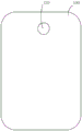
图1为本申请实施例提供的一种显示面板的结构示意图;FIG. 1 is a schematic structural diagram of a display panel provided by an embodiment of the present application;
图2为本申请实施例提供的一种显示面板制备过程中处于打印透明胶层123后的状态的结构示意图;FIG. 2 is a schematic structural diagram of a state after printing a transparent
图3为本申请实施例提供的另一种显示面板的结构示意图;FIG. 3 is a schematic structural diagram of another display panel provided by an embodiment of the present application;
图4为本申请实施例提供的又一种显示面板的结构示意图;FIG. 4 is a schematic structural diagram of another display panel provided by an embodiment of the present application;
图5为本申请实施例提供的一种显示面板的制备方法的流程图。FIG. 5 is a flow chart of a method for manufacturing a display panel provided by an embodiment of the present application.
附图标记:Reference signs:
100-显示区域;100 - display area;
110-基底层;110 - basal layer;
120-遮光结构、121-开口、122-黑色胶层、123-透明胶层;120-shading structure, 121-opening, 122-black adhesive layer, 123-transparent adhesive layer;
130-像素结构;130-pixel structure;
140-封装层;140-encapsulation layer;
150-平坦层;150 - flat layer;
160-触控层。160 - Touch layer.
具体实施方式Detailed ways
下面详细描述本申请,本申请的实施例的示例在附图中示出,其中自始至终相同或类似的标号表示相同或类似的部件或具有相同或类似功能的部件。此外,如果已知技术的详细描述对于示出的本申请的特征是不必要的,则将其省略。下面通过参考附图描述的实施例是示例性的,仅用于解释本申请,而不能解释为对本申请的限制。The present application is described in detail below, and examples of embodiments of the present application are shown in the drawings, wherein the same or similar reference numerals denote the same or similar components or components having the same or similar functions throughout. Also, detailed descriptions of known technologies will be omitted if they are not necessary to illustrate the features of the present application. The embodiments described below by referring to the figures are exemplary only for explaining the present application, and are not construed as limiting the present application.
本技术领域技术人员可以理解,除非另外定义,这里使用的所有术语(包括技术术语和科学术语),具有与本申请所属领域中的普通技术人员的一般理解相同的意义。还应该理解的是,诸如通用字典中定义的那些术语,应该被理解为具有与现有技术的上下文中的意义一致的意义,并且除非像这里一样被特定定义,否则不会用理想化或过于正式的含义来解释。Those skilled in the art can understand that, unless otherwise defined, all terms (including technical terms and scientific terms) used herein have the same meanings as commonly understood by those of ordinary skill in the art to which this application belongs. It should also be understood that terms, such as those defined in commonly used dictionaries, should be understood to have meanings consistent with their meaning in the context of the prior art, and unless specifically defined as herein, are not intended to be idealized or overly Formal meaning to explain.
本技术领域技术人员可以理解,除非特意声明,这里使用的单数形式“一”、“一个”、“所述”和“该”也可包括复数形式。应该进一步理解的是,本申请的说明书中使用的措辞“包括”是指存在所述特征、整数、步骤、操作、元件和/或组件,但是并不排除存在或添加一个或多个其他特征、整数、步骤、操作、元件、组件和/或它们的组。应该理解,当我们称元件被“连接”或“耦接”到另一元件时,它可以直接连接或耦接到其他元件,或者也可以存在中间元件。此外,这里使用的“连接”或“耦接”可以包括无线连接或无线耦接。这里使用的措辞“和/或”包括一个或更多个相关联的列出项的全部或任一单元和全部组合。Those skilled in the art will understand that unless otherwise stated, the singular forms "a", "an", "said" and "the" used herein may also include plural forms. It should be further understood that the word "comprising" used in the specification of the present application refers to the presence of said features, integers, steps, operations, elements and/or components, but does not exclude the presence or addition of one or more other features, Integers, steps, operations, elements, components, and/or groups thereof. It will be understood that when an element is referred to as being "connected" or "coupled" to another element, it can be directly connected or coupled to the other element or intervening elements may also be present. Additionally, "connected" or "coupled" as used herein may include wireless connection or wireless coupling. The expression "and/or" used herein includes all or any elements and all combinations of one or more associated listed items.
下面以具体地实施例对本申请的技术方案以及本申请的技术方案如何解决上述技术问题进行详细说明。The technical solution of the present application and how the technical solution of the present application solves the above technical problems will be described in detail below with specific embodiments.
本申请实施例提供一种显示面板,参见图1所示,该显示面板包括显示区域100,显示区域100包括孔区域,该显示面板还包括:基底层110和遮光结构120。An embodiment of the present application provides a display panel, as shown in FIG. 1 , the display panel includes a
遮光结构120设于基底层110的一侧,遮光结构120具有开口121,并且遮光结构120与孔区域中的周边区域对应;沿孔区域的径向,遮光结构120从内周边指向外周边的第一尺寸小于孔区域的设计边框值。可选地,设计边框值不大于0.5mm(毫米)。The light-shielding
本申请实施例的显示面板沿孔区域的径向,遮光结构120从内周边指向外周边的第一尺寸小于孔区域的设计边框值,从而满足边框的设计边框值更小的贴合需求,实现AAHole窄边框的设计,减小显示面板Panle成本。In the display panel of the embodiment of the present application, along the radial direction of the hole area, the first size of the light-shielding
在一些实施例中,参见图1所示,遮光结构120包括与孔区域中的周边区域对应的黑色胶层122或吸光胶层。黑色胶层122或吸光胶层的内周边形成开口121的边界。In some embodiments, referring to FIG. 1 , the light-shielding
作为一种示例,参见图1所示,遮光结构120包括黑色胶层122,黑色胶层122的内周边形成开口121的边界。可以想得到是,吸光胶层与黑色胶层122的设置一致,吸光胶层是通过吸光实现遮光,黑色胶层122是通过黑色遮挡光线实现遮光。As an example, as shown in FIG. 1 , the
作为一种示例,黑色胶层122的形状为环形,开口121处用于开孔放置设置摄像头。可选地,黑色胶层122的内周边与外周边的距离为0.1mm以内。As an example, the
可选地,黑色胶层122的形状也可以是矩形,矩形的中部具有至少一个开口121形状,用于对应设置至少一个摄像头。在实际应用中,可以根据产品的设计,设计黑色胶层122或吸光胶层的形状。Optionally, the shape of the black
在一些实施例中,遮光结构120还包括:设于基底层110的一侧的透明胶层123,且透明胶层123与孔区域中的周边区域对应。黑色胶层122或吸光胶层对应设于透明胶层123远离基底层110的一侧。In some embodiments, the light-shielding
作为一种示例,参见图2所示,示出了与显示面板的孔区域的透明胶层123。透明胶层123为透明的,在显示面板的制备过程中,打印一层透明胶层123之后,会在透明胶层123远离基底层110一侧制备黑色胶层122或吸光胶层,在设置摄像头时,开口121处会挖孔,使得透明胶层123的形状与黑色胶层122或吸光胶层的形状匹配一致。也就是,透明胶层123与孔区域中的周边区域对应。As an example, see FIG. 2 , which shows a
在一些实施例中,参见图3所示,沿垂直于基底层110的方向,遮光结构120远离基底层110的一侧的高度、大于孔区域周围的显示区域100中的像素结构130远离基底层110的一侧的高度。In some embodiments, as shown in FIG. 3 , along the direction perpendicular to the
可选地,参见图3所示,图中箭头所示为光线,像素结构130的光线经遮光结构120的遮挡后,发光光路受到限制,使得遮光结构120对应的显示区域不显示图像。Optionally, as shown in FIG. 3 , the arrows in the figure indicate light. After the light of the
在一些实施例中,参见图3所示,遮光结构120远离基底层110的一侧在基底层110的正投影,比遮光结构120靠近基底层110的一侧的正投影靠近像素结构130。In some embodiments, as shown in FIG. 3 , the orthographic projection of the side of the
在一些实施例中,参见图3所示,像素结构130远离基底层110的一侧设有封装层140。封装层140包围在遮光结构120的周围。In some embodiments, as shown in FIG. 3 , an
可选地,参见图3所示,封装层140与遮光结构120的接触面的形状相匹配,封装层140与遮光结构120的接触面均为预定倾斜角度的斜面。在实际应用中,由于封装层140包括有机物层,在对遮光结构120封装时,对应形成斜面。Optionally, as shown in FIG. 3 , the shape of the contact surface of the
可选地,参见图3所示,封装层140沿垂直于基底层110的方向的高度与遮光结构120沿垂直于基底层110的方向的高度一致。Optionally, as shown in FIG. 3 , the height of the
在一些实施例中,参见图4所示,封装层140和遮光结构120均远离基底层110的一侧依次设有平坦层150和触控层160。In some embodiments, as shown in FIG. 4 , the
本申请的发明人进一步经过研究发现,FMLOC(Flexible Multi-Layer On Cell,柔性多层触控技术)工艺会有IJP(Ink Jet Printing,喷墨打印)工艺,可以用IJP在AAHole区域打印遮光结构120的黑色胶层122、透明胶层123和吸光胶层,遮光结构120可以起到平坦及遮光效果。The inventors of the present application have found through further research that FMLOC (Flexible Multi-Layer On Cell, flexible multi-layer touch technology) process will have IJP (Ink Jet Printing, inkjet printing) process, and IJP can be used to print light-shielding structures in the AAHole area The black
在一些实施例中,遮光结构120沿垂直于基底层110的方向的高度为8μm(微米)-20μm。可选地,本申请实施例中的数值范围都包含上下限值,例如遮光结构120沿垂直于基底层110的方向的高度范围包括8μm和20μm,全文类似之处不再赘述。In some embodiments, the height of the
可选地,黑色胶层122、透明胶层123和吸光胶层沿垂直于基底层110的方向的高度范围均为8μm-10μm。Optionally, the heights of the black
基于同一发明构思,本申请实施例还提供一种显示装置,包括:本申请任一实施例的显示面板。Based on the same inventive concept, an embodiment of the present application further provides a display device, including: the display panel of any embodiment of the present application.
基于同一发明构思,本申请实施例还提供一种显示面板的制备方法,应用于本申请任一实施例的显示面板,参见图5所示,该显示面板的制备方法包括如下步骤:Based on the same inventive concept, the embodiment of the present application also provides a method for preparing a display panel, which is applied to the display panel in any embodiment of the present application, as shown in FIG. 5 , the method for preparing the display panel includes the following steps:
S501、在基底层110的一侧、且与显示面板的显示区域100的孔区域相对应之处,打印遮光胶结构;遮光胶结构具有初始开口。S501. Print a light-shielding glue structure on one side of the
S502、对遮光胶结构进行固化处理,得到遮光结构120;遮光结构120具有开口121,并且遮光结构120与孔区域中的周边区域对应,且沿孔区域的径向,遮光结构120从内周边指向外周边的第一尺寸小于孔区域的设计边框值。S502, curing the light-shielding glue structure to obtain a light-shielding
可选地,开口121的形状由初始开口固化后形成。Optionally, the shape of the
在一些实施例中,对遮光胶结构进行固化处理,得到遮光结构120,包括:In some embodiments, the light-shielding glue structure is cured to obtain the light-shielding
参见图2所示,在基底层110的一侧、且与显示面板的显示区域100的孔区域相对应之处,打印一层透明胶层123。Referring to FIG. 2 , on one side of the
参见图1所示,在透明胶层123远离基底层110的一侧,且与显示面板的显示区域100的孔区域中的周边区域相对应之处,打印黑色胶层122或吸光胶层;黑色胶层122或吸光胶层具有开口。1, on the side of the transparent
可选地,在基底层110的一侧、且与显示面板的显示区域100的孔区域相对应之处,打印遮光胶结构包括:在基底层110的一侧、且与显示面板的显示区域100的孔区域相对应之处,打印黑色胶层122或吸光胶层。Optionally, on one side of the
本申请实施例的制备方法采用打印遮光胶结构的方式,可以降低遮光结构的贴合精度要求,使得沿孔区域的径向,遮光结构120从内周边指向外周边的第一尺寸小于孔区域的设计边框值,进一步满足边框的设计边框值更小的贴合需求,实现AA Hole窄边框的设计,减小显示面板Panle成本。The preparation method of the embodiment of the present application adopts the method of printing the light-shielding glue structure, which can reduce the lamination accuracy requirements of the light-shielding structure, so that along the radial direction of the hole area, the first dimension of the light-shielding
在工艺制备的过程中,本申请的发明人考虑到AA Hole的边框的宽度较宽,为减小边框各个工艺段都在调整,遮光结构120的贴合精度在0.6mm-1.0mm,无法满足AA Hole的边框等于或小于0.5mm的需求。In the process of process preparation, the inventors of the present application considered that the width of the frame of AA Hole is relatively wide. In order to reduce the width of the frame, each process section is adjusted. The bonding accuracy of the light-shielding
可选地,本申请实施例利用FMLOC的IJP工艺,可以用IJP在AA Hole区域打印遮光结构120的黑色胶层122、透明胶层123和吸光胶层,形成的遮光结构120可以起到平坦及遮光效果。Optionally, the embodiment of the present application utilizes the IJP process of FMLOC, and IJP can be used to print the black
本申请实施例利用FMLOC IJP工艺在AA Hole区域打印遮光的遮光结构120,使得后续工序中无需贴合遮光结构120,进一步满足边框的设计边框值更小的贴合需求。In the embodiment of the present application, the FMLOC IJP process is used to print the light-shielding
应用本申请实施例的制备方法,在现有工艺下进行调整,无需成本增加且降低后续资材成本。而且,本申请实施例采用IJP工艺,提高了工艺的贴合精度,可以适应边框的设计边框值更小的贴合需求。By applying the preparation method of the embodiment of the present application, adjustments are made under the existing process, without increasing the cost and reducing the cost of subsequent materials. Moreover, the embodiment of the present application adopts the IJP process, which improves the lamination accuracy of the process, and can meet the lamination requirements of the design frame with a smaller frame value.
可选地,制备遮光结构120的透明胶层123、黑色胶层122以及吸光胶层,是在AAHole的周边区域需要遮光处滴IJP,后进行UV处理固化,得到遮光结构120。Optionally, to prepare the transparent
应用本申请实施例,至少能够实现如下有益效果:By applying the embodiments of the present application, at least the following beneficial effects can be achieved:
(1)本申请实施例的显示面板沿孔区域的径向,遮光结构120从内周边指向外周边的第一尺寸小于孔区域的设计边框值,从而满足边框的设计边框值更小的贴合需求,实现AA Hole窄边框的设计,减小显示面板Panle成本。(1) In the display panel of the embodiment of the present application, along the radial direction of the hole area, the first size of the light-shielding
(2)本申请实施例的制备方法采用打印遮光胶结构的方式,可以降低遮光结构的贴合精度要求,使得沿孔区域的径向,遮光结构120从内周边指向外周边的第一尺寸小于孔区域的设计边框值,进一步满足边框的设计边框值更小的贴合需求,实现AA Hole窄边框的设计,减小显示面板Panle成本。(2) The preparation method of the embodiment of the present application adopts the method of printing the light-shielding glue structure, which can reduce the lamination accuracy requirements of the light-shielding structure, so that along the radial direction of the hole area, the first dimension of the light-shielding
(3)本申请实施例利用FMLOC的IJP工艺,可以用IJP在AA Hole区域打印遮光结构120的黑色胶层122、透明胶层123和吸光胶层,形成的遮光结构120可以起到平坦及遮光效果。(3) In the embodiment of the present application, the IJP process of FMLOC can be used to print the black
(4)本申请实施例利用FMLOC IJP工艺在AA Hole区域打印遮光的遮光结构120,使得后续工序中无需贴合遮光结构120,进一步满足边框的设计边框值更小的贴合需求。(4) In the embodiment of the present application, the FMLOC IJP process is used to print the light-shielding
本技术领域技术人员可以理解,本申请中已经讨论过的各种操作、方法、流程中的步骤、措施、方案可以被交替、更改、组合或删除。进一步地,具有本申请中已经讨论过的各种操作、方法、流程中的其他步骤、措施、方案也可以被交替、更改、重排、分解、组合或删除。进一步地,现有技术中的具有与本申请中公开的各种操作、方法、流程中的步骤、措施、方案也可以被交替、更改、重排、分解、组合或删除。Those skilled in the art can understand that the various operations, methods, and steps, measures, and schemes in the processes that have been discussed in this application can be replaced, changed, combined, or deleted. Furthermore, the various operations, methods, and other steps, measures, and schemes in the processes that have been discussed in this application may also be replaced, changed, rearranged, decomposed, combined, or deleted. Further, steps, measures, and schemes in the prior art that have operations, methods, and processes disclosed in the present application may also be alternated, changed, rearranged, decomposed, combined, or deleted.
在本申请的描述中,需要理解的是,术语“中心”、“上”、“下”、“前”、“后”、“左”、“右”、“竖直”、“水平”、“顶”、“底”、“内”、“外”等指示的方位或位置关系为基于附图所示的方位或位置关系,仅是为了便于描述本申请和简化描述,而不是指示或暗示所指的装置或元件必须具有特定的方位、以特定的方位构造和操作,因此不能理解为对本申请的限制。In the description of this application, it is to be understood that the terms "center", "upper", "lower", "front", "rear", "left", "right", "vertical", "horizontal", The orientations or positional relationships indicated by "top", "bottom", "inner", "outer", etc. are based on the orientations or positional relationships shown in the drawings, and are only for the convenience of describing the application and simplifying the description, rather than indicating or implying References to devices or elements must have a particular orientation, be constructed, and operate in a particular orientation and therefore should not be construed as limiting the application.
术语“第一”、“第二”仅用于描述目的,而不能理解为指示或暗示相对重要性或者隐含指明所指示的技术特征的数量。由此,限定有“第一”、“第二”的特征可以明示或者隐含地包括一个或者更多个该特征。在本申请的描述中,除非另有说明,“多个”的含义是两个或两个以上。The terms "first" and "second" are used for descriptive purposes only, and cannot be interpreted as indicating or implying relative importance or implicitly specifying the quantity of indicated technical features. Thus, a feature defined as "first" and "second" may explicitly or implicitly include one or more of these features. In the description of the present application, unless otherwise specified, "plurality" means two or more.
在本申请的描述中,需要说明的是,除非另有明确的规定和限定,术语“安装”、“相连”、“连接”应做广义理解,例如,可以是固定连接,也可以是可拆卸连接,或一体地连接;可以是直接相连,也可以通过中间媒介间接相连,可以是两个元件内部的连通。对于本领域的普通技术人员而言,可以具体情况理解上述术语在本申请中的具体含义。In the description of this application, it should be noted that unless otherwise specified and limited, the terms "installation", "connection", and "connection" should be understood in a broad sense, for example, it can be a fixed connection or a detachable connection. Connected, or integrally connected; it can be directly connected, or indirectly connected through an intermediary, and it can be the internal communication of two elements. Those of ordinary skill in the art can understand the specific meanings of the above terms in this application in specific situations.
在本说明书的描述中,具体特征、结构、材料或者特点可以在任何的一个或多个实施例或示例中以合适的方式结合。In the description of this specification, specific features, structures, materials or characteristics may be combined in any one or more embodiments or examples in an appropriate manner.
应该理解的是,虽然附图的流程图中的各个步骤按照箭头的指示依次显示,但是这些步骤并不是必然按照箭头指示的顺序依次执行。除非本文中有明确的说明,这些步骤的执行并没有严格的顺序限制,其可以以其他的顺序执行。而且,附图的流程图中的至少一部分步骤可以包括多个子步骤或者多个阶段,这些子步骤或者阶段并不必然是在同一时刻执行完成,而是可以在不同的时刻执行,其执行顺序也不必然是依次进行,而是可以与其他步骤或者其他步骤的子步骤或者阶段的至少一部分轮流或者交替地执行。It should be understood that although the various steps in the flow chart of the accompanying drawings are displayed sequentially according to the arrows, these steps are not necessarily executed sequentially in the order indicated by the arrows. Unless otherwise specified herein, there is no strict order restriction on the execution of these steps, and they can be executed in other orders. Moreover, at least some of the steps in the flowcharts of the accompanying drawings may include multiple sub-steps or multiple stages, and these sub-steps or stages may not necessarily be executed at the same time, but may be executed at different times, and the order of execution is also It is not necessarily performed sequentially, but may be performed alternately or alternately with at least a part of other steps or sub-steps or stages of other steps.
以上所述仅是本申请的部分实施方式,应当指出,对于本技术领域的普通技术人员来说,在不脱离本申请原理的前提下,还可以做出若干改进和润饰,这些改进和润饰也应视为本申请的保护范围。The above description is only part of the implementation of the present application, and it should be pointed out that for those of ordinary skill in the art, without departing from the principle of the present application, some improvements and modifications can also be made, and these improvements and modifications are also It should be regarded as the protection scope of this application.
Claims (8)
Priority Applications (1)
| Application Number | Priority Date | Filing Date | Title |
|---|---|---|---|
| CN202011061603.4A CN112086017B (en) | 2020-09-30 | 2020-09-30 | Display panel, display device and preparation method of display panel |
Applications Claiming Priority (1)
| Application Number | Priority Date | Filing Date | Title |
|---|---|---|---|
| CN202011061603.4A CN112086017B (en) | 2020-09-30 | 2020-09-30 | Display panel, display device and preparation method of display panel |
Publications (2)
| Publication Number | Publication Date |
|---|---|
| CN112086017A CN112086017A (en) | 2020-12-15 |
| CN112086017B true CN112086017B (en) | 2023-05-12 |
Family
ID=73730118
Family Applications (1)
| Application Number | Title | Priority Date | Filing Date |
|---|---|---|---|
| CN202011061603.4A Active CN112086017B (en) | 2020-09-30 | 2020-09-30 | Display panel, display device and preparation method of display panel |
Country Status (1)
| Country | Link |
|---|---|
| CN (1) | CN112086017B (en) |
Families Citing this family (1)
| Publication number | Priority date | Publication date | Assignee | Title |
|---|---|---|---|---|
| CN117975822A (en) * | 2024-01-31 | 2024-05-03 | 昆山国显光电有限公司 | Display module, manufacturing method of display module and electronic equipment |
Citations (3)
| Publication number | Priority date | Publication date | Assignee | Title |
|---|---|---|---|---|
| CN109001933A (en) * | 2018-08-10 | 2018-12-14 | 厦门天马微电子有限公司 | A kind of display panel, its production method and display device |
| CN110278303A (en) * | 2019-06-28 | 2019-09-24 | Oppo广东移动通信有限公司 | Electronic equipment |
| CN110634795A (en) * | 2019-10-23 | 2019-12-31 | 京东方科技集团股份有限公司 | Preparation method of array substrate, array substrate and display device |
Family Cites Families (22)
| Publication number | Priority date | Publication date | Assignee | Title |
|---|---|---|---|---|
| EP1859662B1 (en) * | 2005-03-14 | 2015-08-05 | Ricoh Company, Ltd. | Method of manufacturing a multilayer wiring structure |
| CN106520055A (en) * | 2016-11-07 | 2017-03-22 | 南京诺邦新材料有限公司 | Dual-curing display screen shading adhesive for ink-jet printing and preparation method of dual-curing shading adhesive |
| CN106547143B (en) * | 2017-01-24 | 2019-10-15 | 京东方科技集团股份有限公司 | Manufacturing method of display substrate, display substrate and display device |
| WO2018228031A1 (en) * | 2017-06-16 | 2018-12-20 | Guangdong Oppo Mobile Telecommunications Corp., Ltd. | Housing, method for producing the same and mobile terminal |
| JP6919145B2 (en) * | 2017-08-09 | 2021-08-18 | 株式会社飯沼ゲージ製作所 | Mask manufacturing equipment and mask manufacturing method |
| CN110034152B (en) * | 2018-01-12 | 2023-08-04 | 京东方科技集团股份有限公司 | Display panel, manufacturing method thereof, and display device |
| US10917506B2 (en) * | 2018-02-05 | 2021-02-09 | Guangdong Oppo Mobile Telecommunications Corp., Ltd. | Terminal display assembly and mobile terminal |
| CN110323547B (en) * | 2018-03-31 | 2022-10-28 | Oppo广东移动通信有限公司 | Electronic device and control method of electronic device |
| CN108681131B (en) * | 2018-07-27 | 2021-07-30 | 厦门天马微电子有限公司 | Display device |
| CN111047980B (en) * | 2018-10-12 | 2021-12-14 | 华为技术有限公司 | Flexible display panels and terminal equipment |
| US10937993B2 (en) * | 2018-12-28 | 2021-03-02 | Wuhan China Star Optoelectronics Semiconductor Display Co., Ltd. | Organic light-emitting diode display panel having under-the-screen structure and display device thereof |
| CN109445171B (en) * | 2018-12-29 | 2021-07-09 | 厦门天马微电子有限公司 | Display module, display device and manufacturing method of display device |
| KR102578991B1 (en) * | 2019-02-19 | 2023-09-15 | 삼성전자주식회사 | Electronic device for controlling pixels adjacent to sensor disposed in display |
| CN110716340A (en) * | 2019-09-23 | 2020-01-21 | 武汉华星光电技术有限公司 | Display device, electronic equipment and manufacturing method of display device |
| CN110838262B (en) * | 2019-11-15 | 2022-03-01 | Oppo广东移动通信有限公司 | Cover plate assembly, preparation method of cover plate assembly and electronic equipment |
| CN110993819B (en) * | 2019-12-04 | 2021-07-23 | 深圳市华星光电半导体显示技术有限公司 | Display panel and method of making the same |
| CN110969935B (en) * | 2019-12-20 | 2022-02-22 | 京东方科技集团股份有限公司 | Array substrate and display device |
| CN111384141A (en) * | 2020-03-24 | 2020-07-07 | 京东方科技集团股份有限公司 | OLED display panel, manufacturing method thereof, and display device |
| CN111430422B (en) * | 2020-04-02 | 2023-06-20 | 合肥维信诺科技有限公司 | Display panel, manufacturing method thereof and display device |
| CN111430440B (en) * | 2020-04-27 | 2022-07-12 | 武汉华星光电半导体显示技术有限公司 | Display panel |
| CN111583818B (en) * | 2020-05-07 | 2021-07-06 | 武汉华星光电半导体显示技术有限公司 | Display panel and display device |
| CN111628112B (en) * | 2020-07-02 | 2023-04-18 | 京东方科技集团股份有限公司 | Display panel and display device |
-
2020
- 2020-09-30 CN CN202011061603.4A patent/CN112086017B/en active Active
Patent Citations (3)
| Publication number | Priority date | Publication date | Assignee | Title |
|---|---|---|---|---|
| CN109001933A (en) * | 2018-08-10 | 2018-12-14 | 厦门天马微电子有限公司 | A kind of display panel, its production method and display device |
| CN110278303A (en) * | 2019-06-28 | 2019-09-24 | Oppo广东移动通信有限公司 | Electronic equipment |
| CN110634795A (en) * | 2019-10-23 | 2019-12-31 | 京东方科技集团股份有限公司 | Preparation method of array substrate, array substrate and display device |
Also Published As
| Publication number | Publication date |
|---|---|
| CN112086017A (en) | 2020-12-15 |
Similar Documents
| Publication | Publication Date | Title |
|---|---|---|
| US10345856B2 (en) | Foldable display device | |
| CN111769109A (en) | Display panels and display devices | |
| US20220236605A1 (en) | Display cover, manufacturing method thereof, and display device | |
| WO2021190245A1 (en) | Display substrate and manufacturing method therefor, and display apparatus | |
| US12178068B2 (en) | Method of fabricating display device capable of facilitating substrate bonding with alignment key | |
| CN111596484A (en) | Color film substrate and display panel | |
| CN111596485A (en) | A color filter substrate, a display panel, and a display device | |
| CN103533795B (en) | Substrate for display and manufacture method thereof, as well as display device | |
| CN113178536A (en) | Display substrate and display device | |
| WO2014190629A1 (en) | Electronic paper module and display apparatus and manufacturing method for said module | |
| WO2016135811A1 (en) | Light beam direction controlling element and display device | |
| WO2022227469A1 (en) | Light-emitting substrate and display apparatus | |
| US20250164849A1 (en) | Display panel, method for manufacturing display panel, and display device | |
| CN115955879A (en) | Display device and method of manufacturing buffer plate | |
| CN112086017B (en) | Display panel, display device and preparation method of display panel | |
| CN115421327A (en) | Cover plate, display module and manufacturing method thereof, and display device | |
| JP2022535174A (en) | OLED display panel and display device | |
| US11494014B2 (en) | Touch panel, touch display device, and fabrication method thereof | |
| CN114509895A (en) | Backlight module, preparation method thereof and display device | |
| CN112542537B (en) | Quantum dot film layer, backlight module and preparation method of backlight module | |
| CN115457878A (en) | Display module, manufacturing method of display module, and display device | |
| CN114822287A (en) | Display module and manufacturing method thereof | |
| WO2015010387A1 (en) | Substrate and manufacturing method therefor, and display device | |
| WO2019007021A1 (en) | Touch control display device and manufacturing method therefor | |
| CN110473987B (en) | Method for manufacturing substrate and method for manufacturing display device |
Legal Events
| Date | Code | Title | Description |
|---|---|---|---|
| PB01 | Publication | ||
| PB01 | Publication | ||
| SE01 | Entry into force of request for substantive examination | ||
| SE01 | Entry into force of request for substantive examination | ||
| GR01 | Patent grant | ||
| GR01 | Patent grant |