CN112017932B - Corrosion-resistant structure of gas delivery system in plasma processing device - Google Patents
Corrosion-resistant structure of gas delivery system in plasma processing device Download PDFInfo
- Publication number
- CN112017932B CN112017932B CN201910466981.1A CN201910466981A CN112017932B CN 112017932 B CN112017932 B CN 112017932B CN 201910466981 A CN201910466981 A CN 201910466981A CN 112017932 B CN112017932 B CN 112017932B
- Authority
- CN
- China
- Prior art keywords
- gas
- nozzle
- corrosion
- bushing
- cavity
- Prior art date
- Legal status (The legal status is an assumption and is not a legal conclusion. Google has not performed a legal analysis and makes no representation as to the accuracy of the status listed.)
- Active
Links
Images


Classifications
-
- H—ELECTRICITY
- H01—ELECTRIC ELEMENTS
- H01J—ELECTRIC DISCHARGE TUBES OR DISCHARGE LAMPS
- H01J37/00—Discharge tubes with provision for introducing objects or material to be exposed to the discharge, e.g. for the purpose of examination or processing thereof
- H01J37/32—Gas-filled discharge tubes
- H01J37/32431—Constructional details of the reactor
- H01J37/3244—Gas supply means
-
- H—ELECTRICITY
- H01—ELECTRIC ELEMENTS
- H01J—ELECTRIC DISCHARGE TUBES OR DISCHARGE LAMPS
- H01J37/00—Discharge tubes with provision for introducing objects or material to be exposed to the discharge, e.g. for the purpose of examination or processing thereof
- H01J37/32—Gas-filled discharge tubes
- H01J37/32009—Arrangements for generation of plasma specially adapted for examination or treatment of objects, e.g. plasma sources
- H01J37/32082—Radio frequency generated discharge
- H01J37/321—Radio frequency generated discharge the radio frequency energy being inductively coupled to the plasma
- H01J37/3211—Antennas, e.g. particular shapes of coils
-
- H—ELECTRICITY
- H01—ELECTRIC ELEMENTS
- H01J—ELECTRIC DISCHARGE TUBES OR DISCHARGE LAMPS
- H01J37/00—Discharge tubes with provision for introducing objects or material to be exposed to the discharge, e.g. for the purpose of examination or processing thereof
- H01J37/32—Gas-filled discharge tubes
- H01J37/32431—Constructional details of the reactor
- H01J37/32458—Vessel
- H01J37/32477—Vessel characterised by the means for protecting vessels or internal parts, e.g. coatings
-
- H—ELECTRICITY
- H01—ELECTRIC ELEMENTS
- H01J—ELECTRIC DISCHARGE TUBES OR DISCHARGE LAMPS
- H01J2237/00—Discharge tubes exposing object to beam, e.g. for analysis treatment, etching, imaging
- H01J2237/32—Processing objects by plasma generation
- H01J2237/33—Processing objects by plasma generation characterised by the type of processing
- H01J2237/334—Etching
-
- H—ELECTRICITY
- H10—SEMICONDUCTOR DEVICES; ELECTRIC SOLID-STATE DEVICES NOT OTHERWISE PROVIDED FOR
- H10P—GENERIC PROCESSES OR APPARATUS FOR THE MANUFACTURE OR TREATMENT OF DEVICES COVERED BY CLASS H10
- H10P72/00—Handling or holding of wafers, substrates or devices during manufacture or treatment thereof
- H10P72/04—Apparatus for manufacture or treatment
- H10P72/0402—Apparatus for fluid treatment
- H10P72/0418—Apparatus for fluid treatment for etching
- H10P72/0421—Apparatus for fluid treatment for etching for drying etching
Landscapes
- Physics & Mathematics (AREA)
- Engineering & Computer Science (AREA)
- Plasma & Fusion (AREA)
- Chemical & Material Sciences (AREA)
- Analytical Chemistry (AREA)
- Plasma Technology (AREA)
- Drying Of Semiconductors (AREA)
Abstract
本发明涉及一种等离子体处理装置中气体输送系统的耐腐蚀结构,在衬套的气体通道等处设有耐腐蚀性材料的镀层,避免与所输送的腐蚀性气体反应,减少金属污染和颗粒。本发明反向地安装喷嘴,使其可靠地覆盖出气孔内的镀层,以防止耐腐蚀性材料被腔体内产生的等离子体破坏。本发明在喷嘴暴露于腔体一侧的表面形成有耐腐蚀的氧化钇涂层,阻挡等离子体对喷嘴的侵蚀。本发明还在衬套与介质窗及腔体接触的密封面也使用了柔韧的耐腐蚀性材料,如特氟龙,来提高衬套整体的密封效果。本发明可以有效提升衬套的耐腐蚀性、密封性,增加其服役寿命,提高等离子体处理装置的运行稳定性。

The invention relates to a corrosion-resistant structure of a gas conveying system in a plasma processing device. A coating of a corrosion-resistant material is provided on the gas channel of the liner to avoid reaction with the conveyed corrosive gas and reduce metal pollution and particles. . In the invention, the nozzle is reversely installed so that it can reliably cover the plating layer in the air outlet, so as to prevent the corrosion-resistant material from being damaged by the plasma generated in the cavity. In the present invention, a corrosion-resistant yttrium oxide coating is formed on the surface of the nozzle exposed to the cavity to prevent the erosion of the nozzle by plasma. The present invention also uses a flexible corrosion-resistant material, such as Teflon, on the sealing surface where the bush contacts with the medium window and the cavity, so as to improve the overall sealing effect of the bush. The invention can effectively improve the corrosion resistance and sealing performance of the bushing, increase its service life, and improve the operation stability of the plasma processing device.
Description
技术领域technical field
本发明涉及等离子体处理装置,特别涉及一种等离子体处理装置中气体输送系统的耐腐蚀结构。The invention relates to a plasma processing device, in particular to a corrosion-resistant structure of a gas delivery system in a plasma processing device.
背景技术Background technique
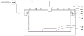
如图1所示,现有的一种电感耦合等离子体处理装置(ICP)中,加载到电感耦合线圈500上的射频功率,通过介质窗400耦合至反应腔100内,将通过气体输送系统供应到反应腔100的工艺气体电离形成等离子体,对放置在静电卡盘600上的晶片700进行工艺处理。As shown in Figure 1, in an existing inductively coupled plasma processing device (ICP), the radio frequency power loaded on the inductively coupled
从气体盒(gas box)输出的工艺气体,先经过分流器(splitter)分成中间进气和边缘进气两路,中间的一路通过介质窗400处安装的进气装置向反应腔100供气;边缘的一路进入到衬套200(liner)的气体通道210中,再通过分布安装在衬套200内壁的多个喷嘴300横向地输送到反应腔100中。所述衬套200位于反应腔100的腔体上,再由衬套200对介质窗400的边缘进行支撑。所述衬套200通过接触腔体而接地。从衬套200主体的内壁向下延伸设置的挡板,环绕布置于反应腔100的腔体内侧,通过该挡板来约束等离子体,保护腔壁等不被侵蚀。The process gas output from the gas box first passes through a splitter and is divided into two paths: the middle inlet and the edge inlet, and the middle path supplies gas to the
然而,衬套200使用铝合金材料制成,并经过阳极氧化处理。该衬套200在使用过程中需要加热到约120摄氏度,如果传输的是腐蚀性气体,尤其是强氧化性气体和酸性气体,会与衬套200基材直接发生化学反应,极易造成气体通道210等腐蚀,引起金属和颗粒污染。例如,所传输的Cl2对气体通道210腐蚀产生的AlCl3进入反应腔100后,沉积在腔体中,对静电卡盘600或晶片700表面造成污染,影响最终的刻蚀精度和良率。由于腐蚀问题,在长期使用中,衬套200也需要频繁更换,带来极高的成本。However, the
图2所示是现有的一种喷嘴插入结构,所述的喷嘴300,包含外径较大的限位段和外径较小的插入段,内部有贯通限位段及插入段的管道来输送气体。该喷嘴300是从气体通道210所在的一侧插入衬套200内壁的,即喷嘴300的插入段穿过衬套200内壁上的出气孔,使该插入段末端位于腔体所在的一侧,该插入段末端的端面可以与衬套200在这一侧的内表面齐平;该喷嘴300的限位段的外径大于出气孔的孔径而使该限位段留在气体通道210内。这样的结构,无法避免反应腔100内产生的等离子体,从喷嘴300与出气孔之间的装配缝隙渗入,而对出气孔、气体通道210等造成侵蚀。Figure 2 shows an existing nozzle insertion structure. The
发明内容Contents of the invention
本发明提供一种等离子体处理装置中气体输送系统的耐腐蚀结构,在气体流径的衬套部位及衬套的密封面处分别设置耐腐蚀性材料的镀层,有效地解决输气过程中的金属污染和颗粒问题,提高衬套整体的密封效果,并通过在出气孔反向安装喷嘴,有效地阻止等离子体对耐腐蚀性材料的破坏。The invention provides a corrosion-resistant structure of a gas conveying system in a plasma processing device. Corrosion-resistant material coatings are respectively arranged on the bushing part of the gas flow path and the sealing surface of the bushing, so as to effectively solve the problem in the gas conveying process. Metal pollution and particle problems, improve the overall sealing effect of the bushing, and reversely install the nozzle in the air outlet, effectively prevent the damage of the plasma to the corrosion-resistant material.
为了达到上述目的,本发明的一个技术方案是提供一种气体输送系统的耐腐蚀结构,所述气体输送系统包含衬套,所述衬套的外壁开设有若干进气孔,该衬套内环绕地设置有气体通道与所述进气孔连通,该衬套内壁还分布开设有若干出气孔与所述气体通道连通,各出气孔上对应安装有喷嘴,工艺气体从所述衬套的进气孔输送到气体通道,进而通过出气孔处的喷嘴输送到反应腔内;In order to achieve the above object, a technical solution of the present invention is to provide a corrosion-resistant structure of a gas delivery system, the gas delivery system includes a liner, the outer wall of the liner is provided with a number of air inlets, and the liner is surrounded by A gas passage is provided to communicate with the air inlet hole, and a number of air outlet holes are distributed on the inner wall of the bush to communicate with the gas passage. Each air outlet hole is correspondingly equipped with a nozzle, and the process gas is discharged from the inlet of the bush. The hole is delivered to the gas channel, and then delivered to the reaction chamber through the nozzle at the outlet hole;
所述衬套的气体通道、进气孔、出气孔,分别设有耐腐蚀性材料的镀层;The gas channels, air inlets, and air outlets of the bushing are respectively provided with coatings of corrosion-resistant materials;
所述喷嘴,包含外径较大的限位段和外径较小的插入段,所述喷嘴内部设有贯通限位段及插入段的工艺气体输送管道;The nozzle includes a limiting section with a larger outer diameter and an insertion section with a smaller outer diameter, and a process gas delivery pipeline passing through the limiting section and the insertion section is provided inside the nozzle;
其中,所述喷嘴的插入段穿过衬套的出气孔,该插入段的末端位于气体通道内;所述喷嘴的限位段留在所述衬套的内表面一侧,该衬套的内表面位于反应腔的腔体内。Wherein, the insertion section of the nozzle passes through the air outlet hole of the bushing, and the end of the insertion section is located in the gas channel; the limiting section of the nozzle is left on the inner surface side of the bushing, and the inner surface of the bushing The surface is located within the chamber of the reaction chamber.
可选地,所述衬套的出气孔是沉孔,该出气孔位于腔体的一侧开口较大,位于气体通道的另一侧开口较小;所述喷嘴的限位段置于所述出气孔位于腔体一侧的开口处。Optionally, the air outlet hole of the bushing is a counterbore, the air outlet hole is located on one side of the cavity and has a larger opening, and the other side of the gas channel has a smaller opening; the limiting section of the nozzle is placed on the The air outlet is located at the opening on one side of the cavity.
可选地,所述衬套的出气孔是两端口径一致的通孔,所述喷嘴的限位段将出气孔位于腔体一侧的开口及出气孔周边的衬套内表面遮蔽。Optionally, the air outlet hole of the bushing is a through hole with the same diameter at both ports, and the limiting section of the nozzle covers the opening of the air outlet hole on one side of the cavity and the inner surface of the bushing around the air outlet hole.
可选地,所述喷嘴的插入段末端位于气体通道内,该插入段末端外围设有凹槽,并在凹槽处环绕设置有钳位件,所述钳位件紧贴衬套内壁位于气体通道的一侧表面并扣住所述凹槽,对喷嘴的位置予以固定。Optionally, the end of the insertion section of the nozzle is located in the gas channel, a groove is provided on the periphery of the end of the insertion section, and a clamping piece is arranged around the groove, and the clamping piece is close to the inner wall of the bushing and positioned on the gas channel. One side surface of the channel and fasten the groove to fix the position of the nozzle.
可选地,所述喷嘴在位于出气孔内部的插入段的表面开设有第一密封槽,所述第一密封槽套设有至少一个密封圈。Optionally, the nozzle is provided with a first sealing groove on the surface of the insertion section inside the air outlet, and the first sealing groove is provided with at least one sealing ring.
可选地,所述衬套由其下方的反应腔腔体承载,所述衬套对其上方的介质窗的边缘承载;所述衬套的本体从内壁向下延伸设置有桶形的挡板,所述挡板环绕布置于反应腔的腔体内侧;Optionally, the liner is carried by the reaction chamber below it, and the liner is carried by the edge of the medium window above it; the body of the liner extends downward from the inner wall and is provided with a barrel-shaped baffle , the baffle is arranged around the inner side of the reaction chamber;
所述衬套在其与反应腔腔体及介质窗接触的密封面处形成有所述耐腐蚀性材料的镀层;所述密封面,包含所述衬套顶部与介质窗接触的若干密封槽,所述衬套与介质窗接触的至少部分顶面位置,所述衬套与腔体接触的至少部分底面位置,所述衬套的本体与挡板拐角处的至少部分底面及外侧面位置。The bushing is formed with a coating of the corrosion-resistant material on its sealing surface in contact with the reaction chamber cavity and the dielectric window; the sealing surface includes several sealing grooves where the top of the bushing contacts the dielectric window, At least part of the top surface of the bush is in contact with the dielectric window, at least a part of the bottom surface of the bush is in contact with the cavity, and at least a part of the bottom and outer side of the bush body and the corner of the baffle.
可选地,所述衬套是经过阳极氧化处理的铝合金材质。Optionally, the bush is made of anodized aluminum alloy.
可选地,所述耐腐蚀性材料的镀层是特氟龙镀层。Optionally, the coating of the corrosion-resistant material is Teflon coating.
可选地,所述喷嘴的限位段在其暴露于腔体一侧的表面,形成有氧化钇的涂层。Optionally, a coating of yttrium oxide is formed on the surface of the limiting section of the nozzle exposed to the cavity.
可选地,暴露于腔体的所述衬套的内表面,形成有氧化钇的涂层。Optionally, the inner surface of the liner exposed to the cavity is coated with yttrium oxide.
本发明的另一个技术方案是提供一种等离子体处理装置,使用上述任意一种气体输送系统的耐腐蚀结构;Another technical solution of the present invention is to provide a plasma processing device using any one of the corrosion-resistant structures of the gas delivery system;
所述等离子体处理装置设有反应腔,所述反应腔的腔体上设置有衬套,所述衬套对其上方的介质窗的边缘承载,所述介质窗上的电感耦合线圈加载射频功率,通过介质窗耦合到反应腔内,将通过气体输送系统引入到反应腔内的工艺气体电离形成等离子体,对反应腔底部放置在静电卡盘上的晶片进行处理;The plasma processing device is provided with a reaction chamber, the chamber body of the reaction chamber is provided with a bushing, the bushing bears on the edge of the dielectric window above it, and the inductively coupled coil on the dielectric window is loaded with radio frequency power , coupled to the reaction chamber through the dielectric window, ionizes the process gas introduced into the reaction chamber through the gas delivery system to form plasma, and processes the wafer placed on the electrostatic chuck at the bottom of the reaction chamber;
工艺气体从所述衬套外壁开设的若干进气孔,进入该衬套内环绕设置的气体通道,经由衬套内壁分布开设的若干出气孔对应安装的喷嘴,输送到反应腔内,所述衬套的气体通道、进气孔、出气孔,分别设有耐腐蚀性材料的镀层;所述喷嘴,包含外径较大的限位段和外径较小的插入段,所述喷嘴内部设有贯通限位段及插入段的工艺气体输送管道;The process gas enters the surrounding gas passages in the liner from several air inlet holes opened on the outer wall of the liner, and is transported into the reaction chamber through a number of air outlet holes distributed on the inner wall of the liner to correspond to the installed nozzles. The gas channel, air inlet, and air outlet of the sleeve are respectively provided with coatings of corrosion-resistant materials; the nozzle includes a limiting section with a larger outer diameter and an insertion section with a smaller outer diameter, and the inside of the nozzle is provided with The process gas delivery pipeline that runs through the limiting section and the insertion section;
其中,所述喷嘴的插入段穿过衬套的出气孔,该插入段的末端位于气体通道内;所述喷嘴的限位段留在所述衬套的内表面一侧,该衬套的内表面位于反应腔的腔体内。Wherein, the insertion section of the nozzle passes through the air outlet hole of the bushing, and the end of the insertion section is located in the gas channel; the limiting section of the nozzle is left on the inner surface side of the bushing, and the inner surface of the bushing The surface is located within the chamber of the reaction chamber.
可选地,所述气体输送系统中,通过气体盒输出的工艺气体,先经过分流器分成中间进气和边缘进气两路,中间进气的一路通过介质窗处安装的进气装置向下输送到反应腔内;边缘进气的一路通过所述衬套的进气孔、气体通道及出气孔处的喷嘴横向地输送到反应腔内。Optionally, in the gas delivery system, the process gas output through the gas box first passes through the flow divider and is divided into two paths, the middle inlet and the edge inlet, and the middle inlet goes through the inlet device installed at the medium window downwards transported into the reaction chamber; one way of the edge air is transported laterally into the reaction chamber through the inlet hole of the liner, the gas channel and the nozzle at the gas outlet.
现有等离子体处理装置的衬套处,气体经过的气体通道等部位是阳极氧化的铝合金,容易和所输送的Cl2等腐蚀性气体反应,出现金属污染和颗粒。与之相比,本发明的衬套在气体经过的气体通道等处设有耐腐蚀性材料的镀层,不容易和Cl2等腐蚀性气体发生反应,从而减少腐蚀对静电卡盘或晶片等造成的金属污染和颗粒。The bushing of the existing plasma processing device, the gas channel through which the gas passes are made of anodized aluminum alloy, which is easy to react with the transported corrosive gas such as Cl 2 , resulting in metal pollution and particles. In contrast, the bushing of the present invention is provided with a coating of a corrosion-resistant material in the gas channel through which the gas passes, which is not easy to react with corrosive gases such as Cl 2 , thereby reducing the impact of corrosion on the electrostatic chuck or wafer. metal pollution and particles.
另外,为防止上述耐腐蚀性材料被腔体内产生的等离子体破坏,本发明还对喷嘴反转,使其可靠地覆盖出气孔内的镀层,这样使得气体通道既不容易和所输送的腐蚀性气体反应,又不会被等离子体破坏。本发明还进一步在喷嘴暴露于腔体一侧的表面镀有Y2O3,来阻挡等离子体对喷嘴的侵蚀。In addition, in order to prevent the above-mentioned corrosion-resistant material from being damaged by the plasma generated in the chamber, the present invention also reverses the nozzle so that it can reliably cover the coating in the gas outlet, so that the gas passage is not easy and the corrosive gas transported The gas reacts without being destroyed by the plasma. In the present invention, the surface of the nozzle exposed to the cavity is further coated with Y 2 O 3 to prevent plasma from eroding the nozzle.
本发明在衬套与介质窗及腔体接触的密封面也使用了柔韧的特氟龙材料,提高了衬套整体的密封效果。The present invention also uses flexible Teflon material on the sealing surface where the bush contacts with the medium window and the cavity, which improves the overall sealing effect of the bush.
本发明利用特氟龙等镀层及反转喷嘴对衬套进行有效的保护,不涉及硬件变动,可以有效地提升衬套的耐腐蚀性,密封性,增加其服役寿命,解决衬套在使用过程中带来的金属污染和颗粒问题,提高刻蚀机台的运行稳定性。The invention uses Teflon and other coatings and reverse nozzles to effectively protect the bushing, does not involve hardware changes, can effectively improve the corrosion resistance and sealing performance of the bushing, increase its service life, and solve the problem of the bushing during use. The metal pollution and particle problems caused by the process can be improved, and the operation stability of the etching machine can be improved.
附图说明Description of drawings
图1是现有的等离子体处理装置的示意图;Fig. 1 is the schematic diagram of existing plasma treatment device;
图2是图1中衬套处的放大图;Figure 2 is an enlarged view of the bushing in Figure 1;
图3是本发明的等离子体处理装置的示意图;Fig. 3 is the schematic diagram of plasma treatment device of the present invention;
图4是图3中衬套处的放大图;Figure 4 is an enlarged view of the bushing in Figure 3;
图5、图6分别是衬套处两个实施结构的放大图;Figure 5 and Figure 6 are enlarged views of the two implementation structures at the bush respectively;
图7是本发明在衬套的出气孔附近的镀层位置及涂层位置的示意图;Fig. 7 is the schematic diagram of the coating position and the coating position near the air outlet of the bushing according to the present invention;
图8是本发明在衬套的进气孔附近的镀层位置及涂层位置的示意图。Fig. 8 is a schematic diagram of the coating position and the coating position near the air inlet hole of the bushing according to the present invention.
具体实施方式Detailed ways
以下结合附图,对本发明的具体实施方式进行说明。The specific embodiments of the present invention will be described below in conjunction with the accompanying drawings.
如图3所示,本发明的电感耦合等离子体处理装置中,加载到电感耦合线圈50上的射频功率,通过介质窗40耦合至反应腔10内,将通过气体输送系统供应到反应腔10的工艺气体电离形成等离子体,对放置在静电卡盘60上的晶片70进行刻蚀等处理。反应腔10的腔体上设置一衬套20,该衬套20对其上方的介质窗40边缘进行承载。所述衬套20通过接触腔体而接地。从衬套20的内壁向下延伸设置有环绕腔体内侧的桶形挡板,实现等离子体约束,保护腔体等部件。该桶形挡板上设置有一个开口,晶片处理前后可以从开口中穿过。As shown in Figure 3, in the inductively coupled plasma processing device of the present invention, the radio frequency power loaded on the inductively coupled
所述的气体输送系统中,通过气体盒输出的工艺气体,先经过分流器分成中间进气和边缘进气两路,中间的一路通过介质窗40处安装的进气装置向反应腔10供气;边缘的一路通过贯穿开设在衬套20外壁的进气孔,进入到环绕在衬套20内的气体通道21中;该衬套20还分布地开设有贯通内壁的多个出气孔,其各自与所述气体通道21相连通,并对应地插入有喷嘴30,将气体输送到反应腔10内。In the gas delivery system, the process gas output through the gas box first passes through the flow divider and is divided into two paths: the middle inlet and the edge inlet, and the middle path supplies gas to the
所述衬套20由铝合金制成,并经过阳极氧化处理,还在所述气体通道21、进气孔和出气孔等多处(下文详述),设有耐腐蚀性材料的镀层,从而防止该衬套20输送的工艺气体对这些部位的腐蚀。示例地,所述气体通道21等处镀有耐卤素气体腐蚀的材料,比如特氟龙(Teflon),则该气体通道21等部位不会被其输送的BCl3、Cl2等气体腐蚀。The
所述的喷嘴30,包含外径较大的限位段32和外径较小的插入段31,内部有贯通限位段32及插入段31的管道来输送气体。相比图2所示的现有喷嘴300,本发明的喷嘴30都是反装的,如图4~图6所示,即从暴露于腔体的衬套20内表面一侧插入到气体通道21:所述喷嘴30的插入段31穿过内壁的出气孔,使该插入段31末端位于气体通道21内,该喷嘴30的限位段32外径大于出气孔的孔径而使该限位段32留在衬套20的内表面一侧。本发明通过反向插入出气孔的喷嘴30,可以将出气孔内耐腐蚀性材料的镀层完全覆盖,有效地阻止反应腔10内产生的等离子体渗入对该镀层的破坏,从而保护出气孔、气体通道21等部位,使其不会被等离子体所侵蚀。The nozzle 30 includes a limiting
图4所示的实施例中,衬套20内壁的出气孔是沉孔,其在暴露于腔体的一侧,即对应衬套20的内表面处的开口较大,以使所述喷嘴30的限位段32恰好置于该侧的开口中。而该喷嘴30的插入段31末端位于气体通道21内,并在该末端外围的凹槽处环绕设置一个钳位件81(clamp),该钳位件81紧贴衬套20内壁位于气体通道21的一侧表面并扣住所述凹槽,对喷嘴30的位置予以固定。所述喷嘴30还在与出气孔内部相对应的插入段31表面开设有密封槽,并套设有至少一个密封圈90,增强密封效果。In the embodiment shown in Fig. 4, the air outlet hole of the inner wall of the
与图4中喷嘴30的限位段32嵌入在出气孔中的结构不同,图5、图6、图7所示的实施例中,衬套20内壁的出气孔是两端口径基本一致的通孔,喷嘴30的限位段32将出气孔在腔体一侧的开口遮蔽,该限位段32直接与出气孔周边的衬套20内表面接触。钳位件80的形式不限,如图5中的钳位件81可以是截面为矩形的环状或板状,图6中的钳位件82可以是截面为圆形的环体;图7中的钳位件83例如是一种夹子,其对应扣在喷嘴30凹槽上方和下方的两部分,大小是不同的,可以仅靠对应凹槽上方(或下方)的部分,与衬套20内壁位于气体通道21的一侧表面紧贴。Different from the structure in which the limiting
如图7、图8所示,本发明中在衬套20内的气体通道21、进气孔22和出气孔23等多处,设有Teflon等耐腐蚀性材料的镀层。在设备运行期间,由于这些部位存在的Teflon镀层具有优异的化学惰性、表面不粘性和气体耐渗透性,可以将流经衬套20的气体与衬套20基材隔绝,不会带来金属和颗粒污染。其中,衬套20的进气孔22和出气孔23内径很小,例如约7mm;对气体通道21等处使用的喷涂方法若无法有效地将孔内覆盖,则可以优选使用流灌的方式(使耐腐蚀性材料的液体流过),将进气孔22和出气孔23内涂覆形成镀层。As shown in Fig. 7 and Fig. 8, in the present invention, the
本发明还在衬套20的多处密封面形成有Teflon等耐腐蚀性材料的镀层。所述密封面包含衬套20顶部接触介质窗40的若干密封槽91、92,衬套20顶面上部分接触介质窗40的位置93,衬套20的底面接触腔体的位置94,衬套20本体与挡板拐角处的外侧面95,等等。由于Teflon具有较高的压缩率和较低的表面粗糙度,因此设置该镀层可以进一步降低衬套20的漏率。同时,Teflon具有优异的耐高低温性能,其使用温度可以在-200℃~260℃区间,并保持优异的性能,因此该镀层非常适用于衬套20的保护。In the present invention, coatings of corrosion-resistant materials such as Teflon are formed on multiple sealing surfaces of the
本发明可以进一步地在喷嘴30限位段32暴露于腔体内的表面321、衬套20内表面上暴露于腔体内的位置24(可选在衬套20内表面上被喷嘴30限位段32覆盖的位置等),分别形成有氧化钇(Y2O3)涂层,以提高耐等离子体侵蚀性能,增加这些部件的使用寿命。In the present invention, the
尽管本发明的内容已经通过上述优选实施例作了详细介绍,但应当认识到上述的描述不应被认为是对本发明的限制。在本领域技术人员阅读了上述内容后,对于本发明的多种修改和替代都将是显而易见的。因此,本发明的保护范围应由所附的权利要求来限定。Although the content of the present invention has been described in detail through the above preferred embodiments, it should be understood that the above description should not be considered as limiting the present invention. Various modifications and alterations to the present invention will become apparent to those skilled in the art upon reading the above disclosure. Therefore, the protection scope of the present invention should be defined by the appended claims.
Claims (10)
Priority Applications (3)
| Application Number | Priority Date | Filing Date | Title |
|---|---|---|---|
| CN201910466981.1A CN112017932B (en) | 2019-05-31 | 2019-05-31 | Corrosion-resistant structure of gas delivery system in plasma processing device |
| TW109107716A TWI713112B (en) | 2019-05-31 | 2020-03-09 | Corrosion-resistant structure of gas delivery system in plasma processing device and plasma processing device using the same |
| US16/885,632 US11348763B2 (en) | 2019-05-31 | 2020-05-28 | Corrosion-resistant structure for a gas delivery system in a plasma processing apparatus |
Applications Claiming Priority (1)
| Application Number | Priority Date | Filing Date | Title |
|---|---|---|---|
| CN201910466981.1A CN112017932B (en) | 2019-05-31 | 2019-05-31 | Corrosion-resistant structure of gas delivery system in plasma processing device |
Publications (2)
| Publication Number | Publication Date |
|---|---|
| CN112017932A CN112017932A (en) | 2020-12-01 |
| CN112017932B true CN112017932B (en) | 2022-11-29 |
Family
ID=73502061
Family Applications (1)
| Application Number | Title | Priority Date | Filing Date |
|---|---|---|---|
| CN201910466981.1A Active CN112017932B (en) | 2019-05-31 | 2019-05-31 | Corrosion-resistant structure of gas delivery system in plasma processing device |
Country Status (3)
| Country | Link |
|---|---|
| US (1) | US11348763B2 (en) |
| CN (1) | CN112017932B (en) |
| TW (1) | TWI713112B (en) |
Families Citing this family (7)
| Publication number | Priority date | Publication date | Assignee | Title |
|---|---|---|---|---|
| WO2021113387A1 (en) | 2019-12-02 | 2021-06-10 | Lam Research Corporation | Impedance transformation in radio-frequency-assisted plasma generation |
| WO2023015296A1 (en) * | 2021-08-06 | 2023-02-09 | Lam Research Corporation | Transformer coupled plasma source design for thin dielectric film deposition |
| US20230162950A1 (en) * | 2021-11-22 | 2023-05-25 | Applied Materials, Inc. | Plasma chamber with a multiphase rotating gas cross-flow and peripheral conductance control rings |
| US12243719B2 (en) * | 2022-06-28 | 2025-03-04 | Taiwan Semiconductor Manufacturing Company, Ltd. | Gas distribution ring for process chamber |
| CN115882158B (en) * | 2022-11-29 | 2025-08-22 | 西安交通大学 | Lithium battery diaphragm coating device and method |
| CN120221372A (en) * | 2023-12-26 | 2025-06-27 | 江苏鲁汶仪器股份有限公司 | An upper air intake uniform gas structure and a plasma etcher |
| CN121519041A (en) * | 2026-01-14 | 2026-02-13 | 上海一郎合金材料有限公司 | Passivation process for large-size corrosion-resistant alloys in aerospace |
Citations (9)
| Publication number | Priority date | Publication date | Assignee | Title |
|---|---|---|---|---|
| JPS61172331A (en) * | 1984-09-17 | 1986-08-04 | Hitachi Ltd | Plasma processor |
| US6013155A (en) * | 1996-06-28 | 2000-01-11 | Lam Research Corporation | Gas injection system for plasma processing |
| CN101522946A (en) * | 2006-10-06 | 2009-09-02 | 旭科技股份有限公司 | Corrosion-resistant member and method for producing same |
| US8133349B1 (en) * | 2010-11-03 | 2012-03-13 | Lam Research Corporation | Rapid and uniform gas switching for a plasma etch process |
| CN102763199A (en) * | 2010-02-12 | 2012-10-31 | 应用材料公司 | Process chamber gas flow improvements |
| CN103329251A (en) * | 2011-01-18 | 2013-09-25 | 应用材料公司 | Semiconductor processing system and methods using capacitively coupled plasma |
| TW201717709A (en) * | 2015-07-10 | 2017-05-16 | Tokyo Electron Ltd | Plasma processing device and shower head |
| CN107527782A (en) * | 2016-06-17 | 2017-12-29 | 三星电子株式会社 | Plasma Processing Apparatus |
| CN108022821A (en) * | 2016-10-28 | 2018-05-11 | 中微半导体设备(上海)有限公司 | The corrosion-resistant means of defence of plasma processing apparatus and gas passage |
Family Cites Families (11)
| Publication number | Priority date | Publication date | Assignee | Title |
|---|---|---|---|---|
| US5885358A (en) * | 1996-07-09 | 1999-03-23 | Applied Materials, Inc. | Gas injection slit nozzle for a plasma process reactor |
| US6170428B1 (en) * | 1996-07-15 | 2001-01-09 | Applied Materials, Inc. | Symmetric tunable inductively coupled HDP-CVD reactor |
| US7128804B2 (en) * | 2000-12-29 | 2006-10-31 | Lam Research Corporation | Corrosion resistant component of semiconductor processing equipment and method of manufacture thereof |
| TWI274393B (en) * | 2002-04-08 | 2007-02-21 | Acm Res Inc | Electropolishing and/or electroplating apparatus and methods |
| US7311797B2 (en) * | 2002-06-27 | 2007-12-25 | Lam Research Corporation | Productivity enhancing thermal sprayed yttria-containing coating for plasma reactor |
| TW587139B (en) * | 2002-10-18 | 2004-05-11 | Winbond Electronics Corp | Gas distribution system and method for the plasma gas in the chamber |
| US20070264443A1 (en) * | 2006-05-09 | 2007-11-15 | Applied Materials, Inc. | Apparatus and method for avoidance of parasitic plasma in plasma source gas supply conduits |
| US20090261065A1 (en) * | 2008-04-18 | 2009-10-22 | Lam Research Corporation | Components for use in a plasma chamber having reduced particle generation and method of making |
| CN106304597B (en) * | 2013-03-12 | 2019-05-10 | 应用材料公司 | Multi-zone gas injection assembly with azimuthal and radial distribution control |
| US9583369B2 (en) * | 2013-07-20 | 2017-02-28 | Applied Materials, Inc. | Ion assisted deposition for rare-earth oxide based coatings on lids and nozzles |
| TWI618111B (en) * | 2017-02-10 | 2018-03-11 | 台灣美日先進光罩股份有限公司 | Side injection gas nozzle of plasma etching chamber and plasma reactor device |
-
2019
- 2019-05-31 CN CN201910466981.1A patent/CN112017932B/en active Active
-
2020
- 2020-03-09 TW TW109107716A patent/TWI713112B/en active
- 2020-05-28 US US16/885,632 patent/US11348763B2/en active Active
Patent Citations (9)
| Publication number | Priority date | Publication date | Assignee | Title |
|---|---|---|---|---|
| JPS61172331A (en) * | 1984-09-17 | 1986-08-04 | Hitachi Ltd | Plasma processor |
| US6013155A (en) * | 1996-06-28 | 2000-01-11 | Lam Research Corporation | Gas injection system for plasma processing |
| CN101522946A (en) * | 2006-10-06 | 2009-09-02 | 旭科技股份有限公司 | Corrosion-resistant member and method for producing same |
| CN102763199A (en) * | 2010-02-12 | 2012-10-31 | 应用材料公司 | Process chamber gas flow improvements |
| US8133349B1 (en) * | 2010-11-03 | 2012-03-13 | Lam Research Corporation | Rapid and uniform gas switching for a plasma etch process |
| CN103329251A (en) * | 2011-01-18 | 2013-09-25 | 应用材料公司 | Semiconductor processing system and methods using capacitively coupled plasma |
| TW201717709A (en) * | 2015-07-10 | 2017-05-16 | Tokyo Electron Ltd | Plasma processing device and shower head |
| CN107527782A (en) * | 2016-06-17 | 2017-12-29 | 三星电子株式会社 | Plasma Processing Apparatus |
| CN108022821A (en) * | 2016-10-28 | 2018-05-11 | 中微半导体设备(上海)有限公司 | The corrosion-resistant means of defence of plasma processing apparatus and gas passage |
Also Published As
| Publication number | Publication date |
|---|---|
| US11348763B2 (en) | 2022-05-31 |
| TW202046403A (en) | 2020-12-16 |
| CN112017932A (en) | 2020-12-01 |
| US20200381213A1 (en) | 2020-12-03 |
| TWI713112B (en) | 2020-12-11 |
Similar Documents
| Publication | Publication Date | Title |
|---|---|---|
| CN112017932B (en) | Corrosion-resistant structure of gas delivery system in plasma processing device | |
| CN110753994B (en) | Multi-Plate Panels for Process Chambers | |
| JP7126431B2 (en) | shower head and gas treater | |
| CN108242381B (en) | Gas supply device, method for manufacturing the same, and plasma processing apparatus | |
| US6592709B1 (en) | Method and apparatus for plasma processing | |
| KR101733283B1 (en) | Non-contact transfer hand | |
| KR20120120245A (en) | Gas distribution showerhead with coating material for semiconductor processing | |
| JP2018082150A (en) | Dual channel shower head with improved profile | |
| TWI808459B (en) | Plasma treatment device and manufacturing method of gas spray ring thereof | |
| CN108022821B (en) | Plasma processing device and corrosion-resistant protection method for gas channel | |
| CN112117214B (en) | Device for purging a slit valve opening in a semiconductor processing chamber | |
| TWI777258B (en) | Corrosion-resistant gas delivery part and plasma processing device therefor | |
| TW201921420A (en) | Tubular electrostatic device | |
| KR100600584B1 (en) | Process Chamber for Semiconductor Manufacturing | |
| US20070144436A1 (en) | Gas coupler for substrate processing chamber | |
| KR20210019851A (en) | Adaptor to supply plasma gas for semiconductor equipment and substrate processing apparatus using the same | |
| CN107376800B (en) | Bushing unit for plasma reaction apparatus | |
| TWI705850B (en) | Corrosion-resistant gas mixing device and plasma processing equipment | |
| KR20200094918A (en) | Apparatus Connecting Gas Line Used In a Semiconductor equipment | |
| KR20000018774A (en) | Flange having o-ring of reaction furnace of cvd device | |
| KR20020089731A (en) | apparatus for manufacturing a substrate |
Legal Events
| Date | Code | Title | Description |
|---|---|---|---|
| PB01 | Publication | ||
| PB01 | Publication | ||
| SE01 | Entry into force of request for substantive examination | ||
| SE01 | Entry into force of request for substantive examination | ||
| GR01 | Patent grant | ||
| GR01 | Patent grant |