CN112005007A - Rotor blade for a wind power installation and wind power installation - Google Patents
Rotor blade for a wind power installation and wind power installation Download PDFInfo
- Publication number
- CN112005007A CN112005007A CN201980025820.7A CN201980025820A CN112005007A CN 112005007 A CN112005007 A CN 112005007A CN 201980025820 A CN201980025820 A CN 201980025820A CN 112005007 A CN112005007 A CN 112005007A
- Authority
- CN
- China
- Prior art keywords
- rotor blade
- laminate
- wind power
- blade
- rope
- Prior art date
- Legal status (The legal status is an assumption and is not a legal conclusion. Google has not performed a legal analysis and makes no representation as to the accuracy of the status listed.)
- Granted
Links
- 238000009434 installation Methods 0.000 title claims description 22
- 239000000835 fiber Substances 0.000 claims description 12
- 238000000926 separation method Methods 0.000 description 9
- 238000004519 manufacturing process Methods 0.000 description 2
- 238000005192 partition Methods 0.000 description 2
- 238000005452 bending Methods 0.000 description 1
- 239000004918 carbon fiber reinforced polymer Substances 0.000 description 1
- 238000010276 construction Methods 0.000 description 1
- 230000001419 dependent effect Effects 0.000 description 1
- 239000011152 fibreglass Substances 0.000 description 1
- 238000003475 lamination Methods 0.000 description 1
- 238000012423 maintenance Methods 0.000 description 1
- 239000000463 material Substances 0.000 description 1
- 238000000034 method Methods 0.000 description 1
- 238000004382 potting Methods 0.000 description 1
- 238000009755 vacuum infusion Methods 0.000 description 1
Images


Classifications
-
- F—MECHANICAL ENGINEERING; LIGHTING; HEATING; WEAPONS; BLASTING
- F03—MACHINES OR ENGINES FOR LIQUIDS; WIND, SPRING, OR WEIGHT MOTORS; PRODUCING MECHANICAL POWER OR A REACTIVE PROPULSIVE THRUST, NOT OTHERWISE PROVIDED FOR
- F03D—WIND MOTORS
- F03D1/00—Wind motors with rotation axis substantially parallel to the air flow entering the rotor
- F03D1/06—Rotors
- F03D1/065—Rotors characterised by their construction elements
- F03D1/0675—Rotors characterised by their construction elements of the blades
-
- F—MECHANICAL ENGINEERING; LIGHTING; HEATING; WEAPONS; BLASTING
- F03—MACHINES OR ENGINES FOR LIQUIDS; WIND, SPRING, OR WEIGHT MOTORS; PRODUCING MECHANICAL POWER OR A REACTIVE PROPULSIVE THRUST, NOT OTHERWISE PROVIDED FOR
- F03D—WIND MOTORS
- F03D1/00—Wind motors with rotation axis substantially parallel to the air flow entering the rotor
- F03D1/06—Rotors
- F03D1/065—Rotors characterised by their construction elements
- F03D1/0658—Arrangements for fixing wind-engaging parts to a hub
-
- F—MECHANICAL ENGINEERING; LIGHTING; HEATING; WEAPONS; BLASTING
- F05—INDEXING SCHEMES RELATING TO ENGINES OR PUMPS IN VARIOUS SUBCLASSES OF CLASSES F01-F04
- F05B—INDEXING SCHEME RELATING TO WIND, SPRING, WEIGHT, INERTIA OR LIKE MOTORS, TO MACHINES OR ENGINES FOR LIQUIDS COVERED BY SUBCLASSES F03B, F03D AND F03G
- F05B2240/00—Components
- F05B2240/20—Rotors
- F05B2240/30—Characteristics of rotor blades, i.e. of any element transforming dynamic fluid energy to or from rotational energy and being attached to a rotor
- F05B2240/301—Cross-section characteristics
-
- F—MECHANICAL ENGINEERING; LIGHTING; HEATING; WEAPONS; BLASTING
- F05—INDEXING SCHEMES RELATING TO ENGINES OR PUMPS IN VARIOUS SUBCLASSES OF CLASSES F01-F04
- F05B—INDEXING SCHEME RELATING TO WIND, SPRING, WEIGHT, INERTIA OR LIKE MOTORS, TO MACHINES OR ENGINES FOR LIQUIDS COVERED BY SUBCLASSES F03B, F03D AND F03G
- F05B2240/00—Components
- F05B2240/20—Rotors
- F05B2240/30—Characteristics of rotor blades, i.e. of any element transforming dynamic fluid energy to or from rotational energy and being attached to a rotor
- F05B2240/302—Segmented or sectional blades
-
- F—MECHANICAL ENGINEERING; LIGHTING; HEATING; WEAPONS; BLASTING
- F05—INDEXING SCHEMES RELATING TO ENGINES OR PUMPS IN VARIOUS SUBCLASSES OF CLASSES F01-F04
- F05B—INDEXING SCHEME RELATING TO WIND, SPRING, WEIGHT, INERTIA OR LIKE MOTORS, TO MACHINES OR ENGINES FOR LIQUIDS COVERED BY SUBCLASSES F03B, F03D AND F03G
- F05B2260/00—Function
- F05B2260/30—Retaining components in desired mutual position
- F05B2260/301—Retaining bolts or nuts
-
- Y—GENERAL TAGGING OF NEW TECHNOLOGICAL DEVELOPMENTS; GENERAL TAGGING OF CROSS-SECTIONAL TECHNOLOGIES SPANNING OVER SEVERAL SECTIONS OF THE IPC; TECHNICAL SUBJECTS COVERED BY FORMER USPC CROSS-REFERENCE ART COLLECTIONS [XRACs] AND DIGESTS
- Y02—TECHNOLOGIES OR APPLICATIONS FOR MITIGATION OR ADAPTATION AGAINST CLIMATE CHANGE
- Y02E—REDUCTION OF GREENHOUSE GAS [GHG] EMISSIONS, RELATED TO ENERGY GENERATION, TRANSMISSION OR DISTRIBUTION
- Y02E10/00—Energy generation through renewable energy sources
- Y02E10/70—Wind energy
- Y02E10/72—Wind turbines with rotation axis in wind direction
-
- Y—GENERAL TAGGING OF NEW TECHNOLOGICAL DEVELOPMENTS; GENERAL TAGGING OF CROSS-SECTIONAL TECHNOLOGIES SPANNING OVER SEVERAL SECTIONS OF THE IPC; TECHNICAL SUBJECTS COVERED BY FORMER USPC CROSS-REFERENCE ART COLLECTIONS [XRACs] AND DIGESTS
- Y02—TECHNOLOGIES OR APPLICATIONS FOR MITIGATION OR ADAPTATION AGAINST CLIMATE CHANGE
- Y02P—CLIMATE CHANGE MITIGATION TECHNOLOGIES IN THE PRODUCTION OR PROCESSING OF GOODS
- Y02P70/00—Climate change mitigation technologies in the production process for final industrial or consumer products
- Y02P70/50—Manufacturing or production processes characterised by the final manufactured product
Landscapes
- Engineering & Computer Science (AREA)
- Life Sciences & Earth Sciences (AREA)
- Sustainable Development (AREA)
- Sustainable Energy (AREA)
- Chemical & Material Sciences (AREA)
- Combustion & Propulsion (AREA)
- Mechanical Engineering (AREA)
- General Engineering & Computer Science (AREA)
- Wind Motors (AREA)
Abstract
A wind power plant rotor blade (200) is proposed, having: a blade outer side (207); a wall portion (205) having a laminate; a blade inner side (206); and at least one first and second rotor blade section (210, 220). At least one first and second rotor blade section (210, 220) are fastened to each other in the parting plane (200a) by means of at least one connecting unit (300). The connection unit (300) has at least one rope (310) with a first end (311) having rope fibres fastened in or on the laminate of the wall portion (205). The connection unit (300) has at least one projection (320) at the first and second rotor blade sections (210, 220), respectively. The projections (320) are each firmly connected to a wall (205) of the rotor blade (200). At least one cord (310) is attached to at least one tab (320). The connection unit (300) has at least one tensioning element (360), by means of which the projections (320) on the first and second rotor blade sections (210, 220) can be tensioned against one another.
Description
Technical Field
The invention relates to a rotor blade for a wind energy installation and to a wind energy installation.
Background
Rotor blades of modern wind energy installations can now be so long that it is no longer possible to transport the rotor blade in one piece. The rotor blade of a wind energy installation can therefore be designed in multiple parts, so that the respective parts are transported separately to the construction site and then assembled there.
WO 2017/085088 a1 shows a rotor blade of a wind energy installation, which has a blade inner side, a blade outer side and a first and a second rotor blade part fastened to one another in a parting plane by means of a fastening unit. The fastening unit has a transverse bolt and a wire rope which is guided through the hole into the second rotor blade section and is clamped in the clamping unit. The second end of the wire rope is clamped in the first clamping unit on the outside of the blade. The second clamping unit is provided on the inner side of the blade.
In the german patent application on which priority is based, the german patent and trademark office has searched for the following documents: DE 2921152A 1, DE 102010046518A 1, DE 102010046519A 1 and WO 2017/085088A 1.
Disclosure of Invention
The object of the present invention is to provide a wind power plant rotor blade and a wind power plant which enable an improved connection of parts of a multi-part wind power plant rotor blade.
This object is achieved by a rotor blade for a wind energy plant according to claim 1.
Accordingly, a wind power plant rotor blade is proposed, which has: the outer side of the blade; a wall having a laminate; the inner side of the blade; and at least one first and second rotor blade section. The at least one first and second rotor blade sections are fastened to each other in the parting plane by means of at least one connecting unit. The connection unit has at least one rope with a first end having rope fibres fastened in or on the laminate of the wall. The connecting unit has at least one protrusion at the first and second rotor blade sections, respectively. The projections are each firmly connected to a wall of the rotor blade. At least one cord is attached to the at least one projection. The connecting unit has at least one tensioning element by means of which the projections on the first and second rotor blade sections can be tensioned against each other.
According to one aspect of the invention, the rope fibres of the rope are fastened in or connected to the laminate in a fan-like opening manner.
According to a further aspect of the invention, each cable has a fastening section, in particular a cable loop, by means of which the cable can be fastened on the projection.
According to a further aspect of the invention, the rotor blade has at least one centering bolt, which projects into the first and second rotor blade part in the region of the parting plane.
According to another aspect of the invention, a connection unit is provided both inside the blade and outside the blade.
According to a further aspect of the invention, a wind energy installation with a rotor blade as described above is proposed.
According to a further aspect of the invention, a wind power installation is proposed, which is provided with at least two rotor blade interfaces and two wind power installation rotor blades, each having: the outer side of the rotor blade; a wall having a laminate; and a rotor blade inner side. The rotor blades are coupled at the rotor blade connection points by means of a plurality of connection units. The connection units each have a cable with a first end having a plurality of cable fibres provided in or on the laminate of the rotor blade. The cable has a fastening section, by means of which the cable is fastened to a projection, which is firmly coupled to the lamination plates of the rotor blade. The connecting units each have a tensioning element, which pretensions the connection points of the projections with the rotor blades.
The invention likewise relates to a wind energy installation having at least one wind energy installation rotor blade as described above.
The invention also relates to a method for mounting a rotor blade of a wind energy installation, having a rotor blade root, a rotor blade tip, a wall, a rotor blade inner side, a rotor blade outer side and at least one first and second rotor blade section which are fastened to one another in a parting plane.
Further embodiments of the invention are the subject matter of the dependent claims.
The invention relates to the following ideas: two components of a rotor blade of a wind energy installation (for example GFK components, i.e. glass fiber reinforced plastic components or carbon fiber reinforced plastic components) are connected in such a way that maintenance of the connection from the inside of the rotor blade is also possible. For connecting two components of a rotor blade of a wind energy installation, a fastening unit is provided.
Drawings
Advantages and embodiments of the invention are explained in detail below with reference to the drawings.
Figure 1 shows a schematic view of a wind energy plant according to the invention,
FIG. 2 shows a schematic view of a multi-piece wind power plant rotor blade according to the invention.
Fig. 3A shows a schematic cross-sectional view of the partition of fig. 2.
Fig. 3B shows a schematic top view of the separation of fig. 2.
FIG. 4A illustrates a schematic cross-sectional view of a separation of the rotor blade of FIG. 2.
FIG. 4B illustrates a schematic top view of a separation of the rotor blade of FIG. 2.
FIG. 5A shows a schematic interface of a separation of the rotor blades of FIG. 2, and
FIG. 5B illustrates a schematic top view of an interface of the rotor blade of FIG. 2.
Detailed Description
Fig. 1 shows a schematic view of a wind energy installation according to the invention. Wind energy plant 100 has a tower 102 and a nacelle 104 on tower 102. An aerodynamic rotor 106 with three rotor blades 200 and a nacelle 110 is arranged on the nacelle 104. When the wind energy installation is in operation, the aerodynamic rotor 106 is set into rotational motion by the wind and thus also rotates the rotor or armature of the generator which is directly or indirectly coupled to the aerodynamic rotor 106. A generator is disposed in nacelle 104 and generates electrical energy. The pitch angle of the rotor blades 200 can be changed by a pitch motor at the rotor blade root of the respective rotor blade 200.
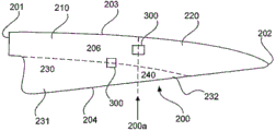
FIG. 2 shows a schematic view of a multi-piece wind power plant rotor blade according to the invention. The rotor blade has a rotor blade root 201, a rotor blade tip 202, a rotor blade leading edge 203 and a rotor blade trailing edge 204 and is for example composed of three sections or segments 210 and 230. The rotor blade 200 has a parting plane 200 a. The rotor blade sections 210 and 230 can be fastened to one another, for example, by means of the connecting unit 300 and the parting plane 200 a. The section 230 can be designed in two parts 231, 232, wherein the first part 231 is fastened to the first section 210 and the second part 232 is fastened to the second section 220.
The rotor blade 200 also has a wall 205, a rotor blade inner side 206 (on the inner side of the wall) and a rotor blade outer side 207. The rotor blade 200 is typically manufactured as follows: the two half-shells are fastened to each other or glued to each other. Thereby a rotor blade inner side 206 and a rotor blade outer side 207 are created, which are the outer surfaces of the rotor blades.
Fig. 3A shows a schematic cross-sectional view of the partition of fig. 2. The wind power plant rotor blade 200 has a first and a second section 210, 220, which are separated from each other by a separation point 200 a.
The first and second rotor blade sections 210, 220 each have thicker walls at their ends 211, 221 facing the parting plane 200a, i.e. the laminate plates 210a, 220a can be designed thicker there. The first and second rotor blade sections 210, 220 are connected to each other via at least one connection unit 300. The connection unit 300 has at least one first rope 310, at least one protrusion 320 and a tensioning element 330. The tensioning element 330 serves to connect or pretension the projections 320 on the first part 210 and the projections 320 on the second part 220 with respect to one another. The connection unit 300 also has at least one cable 310 with a first end 311 having a plurality of cable fibres 311 which are connected or bonded to the laminate 210a, 220a in a force-fitting manner. The cable 310 has a fastening section 313, by means of which the cable 310 is fastened in or on the projection 320. The tab 320 is securely connected to the laminates 210a, 220 a.
Alternatively, the fan-shaped rope fibers 311 can be stitched by means of threads 311a in order to ensure a fiber course when placed dry in the blade mold. Optionally, the fan-shaped rope fibers 311 are placed dry into the laminate or during the manufacture of the laminate.
The protrusion 320 is provided on the rotor blade inner side 206. Correspondingly, the first end 311 of the rope 310 is also provided on the blade inner side 206.
According to an aspect of the invention, the rope fibers 311 of the rope 310 are placed dry in the mould for the blade laminate during manufacturing of the blade laminate. The rotor blade section can then be completed, for example, by means of vacuum infusion. In this case it is possible to realize: after the potting, the fan-shaped cord fibers are connected in a force-fitting manner to the blade material of the rotor blade part.
According to the invention, no through-holes in the laminate are required for connecting the two rotor blade sections to each other. This is particularly advantageous, since the thickness of the laminate can thereby be reduced.
According to the invention, the tensioning element 330 can be tensioned by means of a torque screwdriver. To check the pretensioning force, the tensioning element 330 can be subsequently subjected to a renewed application of torque.
According to an aspect of the invention, the rope loop 311 can be positioned such that the force of lifting the rope fibres with respect to the rest of the blade laminate is reduced. For this purpose, the cable loop can be positioned in the region of the thick-walled laminate close to the flange. The load-transmitting region is provided in the laminate in the region of the unfolded or used laminate. Thus, the lifting force can be reduced by deflecting the rope fibres at the bending point of the flange laminate.
Optionally, in order to further improve the connection between the first and second rotor blade sections 210, 220, at least one centering bolt 350 can be provided in the laminate 210a, 220a in the region of the separation point 200 a.
FIG. 4A illustrates a schematic cross-sectional view, and FIG. 4B illustrates a schematic top view, of a separation of a rotor blade according to an aspect of the present invention. In the embodiment of fig. 3A and 3B, the connection unit 300 is provided on the rotor blade inner side 207, whereas in the embodiment of fig. 4A and 4B, the connection unit 300 is provided both on the rotor blade inner side 206 and on the rotor blade outer side 207. The configuration of the connection unit 300 according to the embodiment of fig. 4A and 4B corresponds to the configuration of the fastening unit 300 of the embodiment of fig. 3A and 3B. Each of the connection units 300 (on the outside of the rotor blade and on the inside of the rotor blade) therefore has at least one cable 310 with a cable fibre 311 which is designed in a fan-like open manner at a first end of the cable and is embedded or fastened in the laminate 222a, 210 a. The cable 310 is connected to a projection 320, which can be designed, for example, as a wedge. By means of the tensioning element 330, the projections 320 can be tensioned relative to each other. The connection of the two rotor blade parts can thus be achieved without through-openings in the region of the laminate plates being required for this purpose. Optionally, a centering bolt 350 can be provided. The thickness of the laminate 320 is greater in the region of the separation than in the rest of the blade. The tabs can be securely connected to the laminates 210a, 220 a.
Fig. 5A shows a schematic cross section of a flanged connection, and fig. 5B shows a schematic top view of a flanged connection according to the invention. In the embodiment of fig. 5A, the flange 270 is connected with a portion 220 of the rotor blade by means of a connection unit 300. For this purpose, the connection unit 300 has a cable 310 which has a cable fiber at a first end 311, which cable fiber is designed in a fan-like manner. Alternatively, the fan-like opened rope fibers 311 can be sewn with thread 311 a. As in the other embodiments, the rope fibers 311 are integrated into the laminate of a part of the rotor blade. The connection unit 300 also has a protrusion or wedge 320, which is connected with the laminate of the rotor blade 200 and accommodates a portion of the rope 310. In particular, the cable loop 313 can be laid around or connected to the projection 320, for example. The connection unit 300 can also have a tensioning element 360, one end of which is screwed, for example, into the connection flange 270. At the other end, a screw can be provided, for example, in order to be able to apply a pretensioning force to the cable.
In the embodiment of fig. 5A and 5B, only half of the fastening unit of fig. 4 is used for fastening the rotor blade to the flange.
In the embodiment of fig. 5A and 5B, two rows of flange connections are shown.
Thus, according to the invention, a multi-part rotor blade is proposed, which advantageously has a reduced laminate thickness in the region of the separation between the first and second rotor blade sections without compromising the stability of the connection.
Claims (7)
1. A wind power plant rotor blade (200) having:
the outer side (207) of the blade,
a wall portion (205) with a laminate,
an inner blade side (206), and
at least one first and second rotor blade section (210, 220) which are fastened to one another in a parting plane (200a) by means of at least one connecting unit (300),
wherein the connection unit (300) has at least one rope (310) with a first end (311) with rope fibres fastened in or connected with the laminate of the wall portion (205),
wherein the connection unit (300) has at least one projection (320) at the first and second rotor blade section (210, 220), respectively, wherein the projections (320) are firmly connected with the laminate of the wall section (205) of the rotor blade (200), respectively,
wherein the cord (310) is attached to the tab (320),
wherein the connection unit (300) has at least one tensioning element (360), by means of which the projections (320) on the first and second rotor blade sections (210, 220) can be pretensioned against one another.
2. The wind power plant rotor blade (200) according to claim 1, wherein
The rope fibers (311) of the rope (310) are fastened in or connected with the laminate in a fan-like open manner.
3. The wind power plant rotor blade (200) according to claim 1 or 2,
each cable (310) has a fastening section (313), in particular a cable loop, by means of which the cable (310) can be fastened on the projection (320).
4. A wind power plant rotor blade (200) according to any of claims 1 to 3, further having:
at least one centering bolt (350) which projects into the first and second rotor blade sections (210, 220) in the region of the parting plane (200 a).
5. The wind power plant rotor blade (200) according to any of claims 1 to 4, wherein
A connection unit (300) is provided on the blade inner side (206) and the blade outer side (207).
6. Wind energy installation having at least one wind energy installation rotor blade according to any of claims 1 to 5.
7. A wind energy installation having:
at least two rotor blade connection points (270), and
at least two wind power plant rotor blades (200) each having: a rotor blade outer side (207); a wall portion (205) having a laminate; and a rotor blade inner side (206),
wherein the wind power plant rotor blade (200) is coupled to a rotor blade connection point (270) by means of a plurality of connection units (300),
wherein the connection units (300) each have a rope (310) having a first end (311) with a plurality of rope fibers arranged in or on a laminate of the rotor blade (200),
wherein the cable (310) has a fastening section (313) by means of which the cable is fastened on a projection (320) which is firmly coupled with a laminate of the rotor blade (200),
wherein the connection units (300) each have at least one tensioning element (360) which pretensions the projection (320) with the rotor blade connection (270).
Applications Claiming Priority (3)
| Application Number | Priority Date | Filing Date | Title |
|---|---|---|---|
| DE102018108906.6A DE102018108906A1 (en) | 2018-04-16 | 2018-04-16 | Wind turbine rotor blade and wind turbine |
| DE102018108906.6 | 2018-04-16 | ||
| PCT/EP2019/059256 WO2019201738A1 (en) | 2018-04-16 | 2019-04-11 | Wind turbine rotor blade and wind turbine |
Publications (2)
| Publication Number | Publication Date |
|---|---|
| CN112005007A true CN112005007A (en) | 2020-11-27 |
| CN112005007B CN112005007B (en) | 2024-03-15 |
Family
ID=66182560
Family Applications (1)
| Application Number | Title | Priority Date | Filing Date |
|---|---|---|---|
| CN201980025820.7A Active CN112005007B (en) | 2018-04-16 | 2019-04-11 | Wind energy installation rotor blade and wind energy installation |
Country Status (5)
| Country | Link |
|---|---|
| US (1) | US11220994B2 (en) |
| EP (1) | EP3781808B1 (en) |
| CN (1) | CN112005007B (en) |
| DE (1) | DE102018108906A1 (en) |
| WO (1) | WO2019201738A1 (en) |
Families Citing this family (2)
| Publication number | Priority date | Publication date | Assignee | Title |
|---|---|---|---|---|
| EP4490403A1 (en) * | 2022-03-10 | 2025-01-15 | Nordex Energy SE & Co. KG | Wind turbine rotor blade and method of joining two rotor blade segments |
| US12018586B2 (en) * | 2022-09-06 | 2024-06-25 | General Electric Company | Airfoil assembly with tensioned blade segments |
Citations (8)
| Publication number | Priority date | Publication date | Assignee | Title |
|---|---|---|---|---|
| US20120070296A1 (en) * | 2010-09-22 | 2012-03-22 | Hendrik Klein | Rotor blade or rotor blade segment for a wind turbine |
| CN102410152A (en) * | 2010-09-22 | 2012-04-11 | 德国恩德能源有限公司 | Rotor blade or rotor blade segment for a wind turbine |
| CN102477938A (en) * | 2010-11-29 | 2012-05-30 | 陆中源 | Wind kinetic energy receiving conversion device |
| CN103732383A (en) * | 2011-04-11 | 2014-04-16 | Lmwp专利控股有限公司 | Wind turbine blade with root region with elongated fastening member provided with metal fibers |
| CN103747944A (en) * | 2011-04-11 | 2014-04-23 | Lmwp专利控股有限公司 | Wind turbine blade with elongated fastening members in the root region thereof |
| EP2930350A1 (en) * | 2014-04-11 | 2015-10-14 | Siemens Aktiengesellschaft | Segmented rotor blade with a bolt connection |
| CN105298740A (en) * | 2015-11-03 | 2016-02-03 | 周方 | Rotor strengthening device of wind driven generator |
| DE102015120113A1 (en) * | 2015-11-20 | 2017-05-24 | Wobben Properties Gmbh | Wind turbine rotor blade and wind turbine |
Family Cites Families (6)
| Publication number | Priority date | Publication date | Assignee | Title |
|---|---|---|---|---|
| DE2921152C2 (en) | 1979-05-25 | 1982-04-22 | Messerschmitt-Bölkow-Blohm GmbH, 8000 München | Rotor blade for wind power plants |
| GB2166202B (en) | 1984-10-30 | 1988-07-20 | Rolls Royce | Hollow aerofoil blade |
| ES2598828T3 (en) * | 2011-04-11 | 2017-01-30 | Lm Wp Patent Holding A/S | Wind turbine blade comprising cylindrical metal inserts in a root region thereof |
| DK3019741T3 (en) * | 2013-07-09 | 2018-03-26 | Vestas Wind Sys As | WINDMILL LIVES WITH SECTIONS THAT ARE ASSEMBLED |
| WO2018121826A1 (en) * | 2016-12-28 | 2018-07-05 | Vestas Wind Systems A/S | Connection joint for a sectional wind turbine rotor blade and associated methods |
| WO2021008666A1 (en) * | 2019-07-12 | 2021-01-21 | Vestas Wind Systems A/S | Connection for split wind turbine blade |
-
2018
- 2018-04-16 DE DE102018108906.6A patent/DE102018108906A1/en not_active Withdrawn
-
2019
- 2019-04-11 WO PCT/EP2019/059256 patent/WO2019201738A1/en not_active Ceased
- 2019-04-11 US US17/045,735 patent/US11220994B2/en active Active
- 2019-04-11 EP EP19717852.8A patent/EP3781808B1/en active Active
- 2019-04-11 CN CN201980025820.7A patent/CN112005007B/en active Active
Patent Citations (8)
| Publication number | Priority date | Publication date | Assignee | Title |
|---|---|---|---|---|
| US20120070296A1 (en) * | 2010-09-22 | 2012-03-22 | Hendrik Klein | Rotor blade or rotor blade segment for a wind turbine |
| CN102410152A (en) * | 2010-09-22 | 2012-04-11 | 德国恩德能源有限公司 | Rotor blade or rotor blade segment for a wind turbine |
| CN102477938A (en) * | 2010-11-29 | 2012-05-30 | 陆中源 | Wind kinetic energy receiving conversion device |
| CN103732383A (en) * | 2011-04-11 | 2014-04-16 | Lmwp专利控股有限公司 | Wind turbine blade with root region with elongated fastening member provided with metal fibers |
| CN103747944A (en) * | 2011-04-11 | 2014-04-23 | Lmwp专利控股有限公司 | Wind turbine blade with elongated fastening members in the root region thereof |
| EP2930350A1 (en) * | 2014-04-11 | 2015-10-14 | Siemens Aktiengesellschaft | Segmented rotor blade with a bolt connection |
| CN105298740A (en) * | 2015-11-03 | 2016-02-03 | 周方 | Rotor strengthening device of wind driven generator |
| DE102015120113A1 (en) * | 2015-11-20 | 2017-05-24 | Wobben Properties Gmbh | Wind turbine rotor blade and wind turbine |
Also Published As
| Publication number | Publication date |
|---|---|
| US20210180561A1 (en) | 2021-06-17 |
| US11220994B2 (en) | 2022-01-11 |
| EP3781808C0 (en) | 2023-06-07 |
| WO2019201738A1 (en) | 2019-10-24 |
| DE102018108906A1 (en) | 2019-10-17 |
| EP3781808A1 (en) | 2021-02-24 |
| EP3781808B1 (en) | 2023-06-07 |
| CN112005007B (en) | 2024-03-15 |
Similar Documents
| Publication | Publication Date | Title |
|---|---|---|
| DK2204577T3 (en) | Flat back insert for wind turbine blades | |
| EP1965074B1 (en) | A wind turbine multi-panel blade | |
| US10710321B2 (en) | Rotor blade mold assembly and method for forming rotor blade | |
| US9920739B2 (en) | System and method for securing a conductive cable within a wind turbine rotor blade | |
| CN112912620B (en) | Jointed wind turbine rotor blade having varying material combinations for pin reinforcement along its span | |
| CN108291524B (en) | Wind energy installations Rotor blades and wind energy installations | |
| US11761420B2 (en) | Composite material, a wind turbine blade, a wind turbine and a method for producing a composite material | |
| US9719359B2 (en) | Wind turbine blade comprising resistive heating means | |
| EP3568587B1 (en) | Wind turbine blade, wind turbine and method for producing a wind turbine blade | |
| CN106574602A (en) | Reinforced wind turbine blade components | |
| CN112005007A (en) | Rotor blade for a wind power installation and wind power installation | |
| JP2005147086A (en) | Blade of horizontal axis wind mill | |
| EP3870851B1 (en) | Lightning protection of a segmented wind turbine blade | |
| US11767819B2 (en) | Spacer material, for reducing a bond gap between a beam structure and a blade shell of a segmented rotor blade | |
| CN108138742A (en) | Wind energy plant-rotor blade and wind energy plant | |
| US11732685B2 (en) | Wind turbine blade assembly and methods | |
| EP4204680B1 (en) | Jointed wind turbine rotor blade having improved transitions between varying material combinations | |
| WO2020131044A1 (en) | Wind turbine rotor blade shell with varying fiber types | |
| EP4495415A1 (en) | Spar cap structures comprising glass fiber stacks with conductive elements | |
| WO2025017010A1 (en) | Spar cap structures comprising glass fiber stacks with conductive elements | |
| WO2026067973A1 (en) | Wind turbine blade joints having removable covers and magnetic systems |
Legal Events
| Date | Code | Title | Description |
|---|---|---|---|
| PB01 | Publication | ||
| PB01 | Publication | ||
| SE01 | Entry into force of request for substantive examination | ||
| SE01 | Entry into force of request for substantive examination | ||
| GR01 | Patent grant | ||
| GR01 | Patent grant |