Detailed Description
The present invention will be described in further detail with reference to the accompanying drawings and examples. It is to be understood that the specific embodiments described herein are merely illustrative of the invention and are not limiting of the invention. It should be further noted that, for the convenience of description, only some of the structures related to the present invention are shown in the drawings, not all of the structures.
Example one
Fig. 1 is a schematic structural diagram of an aerial charging system for an unmanned aerial vehicle according to an embodiment of the present invention, and the aerial charging system for an unmanned aerial vehicle according to the embodiment of the present invention can realize aerial charging for an unmanned aerial vehicle to be charged in a process in which the unmanned aerial vehicle executes an aerial flight task, and the unmanned aerial vehicle to be charged does not need to return to the ground to complete charging, so that task execution efficiency of the unmanned aerial vehicle to be charged is improved. As shown in fig. 1, the unmanned aerial vehicle aerial charging system includes a first unmanned aerial vehicle 110 and a second unmanned aerial vehicle 120, wherein the first unmanned aerial vehicle 110 includes a first power supply 111 and a first wireless charging coil 112 electrically connected to the first power supply 111. The second drone 120 includes a second power supply 121, a second wireless charging coil 122 electrically connected to the second power supply 121; in the process of the first drone 110 executing the air flight mission, when the remaining capacity of the first power supply 111 is lower than the set threshold, the second drone 120 takes off to make the position between the second wireless charging coil 122 and the first wireless charging coil 112 satisfy the preset position relationship, and provide the electric energy of the second power supply 121 to the first power supply 111 through the second wireless charging coil 122 and the first wireless charging coil 112.
Further, referring to a schematic structural diagram of a first drone machine shown in fig. 2, the first drone machine further includes a first positioning element 113, a first wireless communication element 114, and a first controller 115; the first positioning element 113 and the first wireless communication element 114 are respectively in communication connection with the first controller 115, and when the remaining power of the first power supply 111 is lower than a set threshold, the first controller 115 sends an alarm instruction to the second unmanned aerial vehicle 120 through the first wireless communication element 114, so that the second unmanned aerial vehicle 120 takes off; wherein the alarm instruction includes the first position information of the first unmanned aerial vehicle 110 obtained through the first positioning element 113. The first Positioning element 113 may be a GPS (Global Positioning System) module; the first power supply 111 is typically a battery.
First wireless charging coil 112 can set up in the optional position of first unmanned aerial vehicle 110 shell, and second wireless charging coil 122 can set up in the optional position of second unmanned aerial vehicle 120 shell to position between convenient second wireless charging coil 122 and the first wireless charging coil 112 satisfies and predetermines the position relation. The preset position relationship preferably can be that the second wireless charging coil 122 and the first wireless charging coil 112 are in up-down correspondence, and the distance between the two should not be too far away, because charging through the wireless charging coil is realized based on the electromagnetic wave induction principle, the electromagnetic field intensity induced when the second wireless charging coil 122 and the first wireless charging coil 112 are in up-down correspondence is the biggest, and charging efficiency is the highest.
Exemplarily, in order to improve flight safety of the first drone 110 and the second drone 120, and reduce the difficulty of making the position between the second wireless charging coil 122 and the first wireless charging coil 112 satisfy the preset positional relationship, as shown in fig. 2, the first drone 110 further includes a first telescopic rod 116, the first wireless charging coil 112 is fixedly connected to the first telescopic rod 116, the first telescopic rod 116 can rotate relatively to the body of the first drone to drive the first wireless charging coil 112 to move, so that the position between the first wireless charging coil 112 and the second wireless charging coil 122 easily satisfies the preset positional relationship. The first controller 115 is further configured to control the telescopic length and/or the telescopic angle of the first telescopic rod 116 according to the first position information of the first drone 110 and the second position information of the second drone 120, so that the position between the second wireless charging coil 122 and the first wireless charging coil 112 satisfies a preset position relationship. Under the drive of first telescopic link 116, first wireless charging coil 112 can keep away from first unmanned aerial vehicle 110's organism, has made things convenient for second unmanned aerial vehicle 120's second wireless charging coil 122 rather than aiming at, has reduced influence each other between first unmanned aerial vehicle 110 and the second unmanned aerial vehicle 120, has improved flight safety nature. The first telescopic rod 116 may be an electric telescopic rod.
It will be appreciated that the infrastructure of the first drone 110 and the infrastructure of the second drone 120 may be the same, with the difference being that the first drone 110 is a drone to be charged that needs to be charged and the second drone 120 is a charging drone that provides electrical energy. Referring to the schematic structural diagram of a second drone shown in fig. 3, the second drone 120 includes a second positioning element 123, a second wireless communication element 124, and a second controller 125; the second positioning element 123 and the second wireless communication element 124 are respectively in communication connection with the second controller 125, and when the second controller 125 receives the alarm instruction through the second wireless communication element 124, the second controller 120 is controlled to take off, and the second position information of the second drone 120 obtained through the second positioning element 123 is sent to the first controller 115 through the second wireless communication element 124 and the first wireless communication element 114. The second positioning element 123 may be a GPS module; the second power supply 121 is typically a battery.
In order to further improve the flight safety of the first drone 110 and the second drone 120, and to reduce the difficulty of making the position between the second wireless charging coil 122 and the first wireless charging coil 112 satisfy the preset positional relationship, as shown in fig. 3, the second drone 120 further includes: the second telescopic rod 126, the second wireless charging coil 122 is fixedly connected to the second telescopic rod 126; second telescopic link 126 can be relative second unmanned aerial vehicle's organism rotary motion to drive the motion of second wireless charging coil 122, make the position between second wireless charging coil 122 and the first wireless charging coil 112 satisfy more easily preset the position relation. The second controller 125 is further configured to control the telescopic length and/or the telescopic angle of the second telescopic rod 126 according to the first position information of the first drone 110 and the second position information of the second drone 120, so that the position between the second wireless charging coil 122 and the first wireless charging coil 112 satisfies a preset position relationship. The second telescopic rod 126 may be an electric telescopic rod.
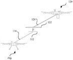
Correspondingly, referring to the schematic diagram of the non-contact electric unmanned aerial vehicle charging in the air shown in fig. 4, the first unmanned aerial vehicle 110 and the second unmanned aerial vehicle 120 interact with each other to obtain respective position information, and the first controller 115 of the first unmanned aerial vehicle 110 controls the first telescopic rod 116 to extend out to the right and back according to the first position information and the second position information of the second unmanned aerial vehicle 120; second unmanned aerial vehicle 120's second controller 125 is according to the second position information of oneself and first unmanned aerial vehicle 110's first position information control oneself second telescopic link 126 the place ahead stretches out left, make the position between second wireless charging coil 122 and the first wireless charging coil 112 satisfy and predetermine the position relation, thereby reach aerial wireless purpose of charging, if unmanned aerial vehicle need charge at the in-process of aerial executive task, the aerial charging system of unmanned aerial vehicle that provides through this embodiment can realize unmanned aerial vehicle's aerial charging, need not to interrupt the task and return ground to charge, unmanned aerial vehicle's task execution efficiency has been improved.
According to the technical scheme, the wireless charging coils are respectively configured for the first unmanned aerial vehicle and the second unmanned aerial vehicle, when a controller of the second unmanned aerial vehicle receives a charging instruction of the first unmanned aerial vehicle, the first unmanned aerial vehicle takes off according to first position information of the first unmanned aerial vehicle, the first unmanned aerial vehicle is continuously close to the second unmanned aerial vehicle, the second telescopic rod of the first unmanned aerial vehicle is controlled to drive the second wireless charging coil to move, the first controller of the first unmanned aerial vehicle controls the first telescopic rod of the first unmanned aerial vehicle to drive the telescopic length and/or telescopic angle of the first wireless charging coil, the position relation between the first wireless charging coil and the second wireless charging coil reaches the preset position relation, the purpose of air wireless charging is achieved, the purpose of air charging for the first unmanned aerial vehicle is achieved, and further the task execution efficiency of the first unmanned aerial vehicle is improved.
Example two
Fig. 5 is a flowchart of an aerial charging method for an unmanned aerial vehicle according to a second embodiment of the present invention, where the method provided in this embodiment is applied to the first unmanned aerial vehicle described in the above embodiment, and is specifically executed by a first controller of the first unmanned aerial vehicle, and is intended to send an alarm instruction to the second unmanned aerial vehicle when detecting that the remaining power of the first power supply is lower than a set threshold, so that the second unmanned aerial vehicle takes off to the air to charge the first power supply of the first unmanned aerial vehicle, thereby achieving the purpose of aerial charging. Wherein explanations of the same or corresponding terms as those of the above-described embodiments are omitted.
Referring to fig. 5, the method for charging an unmanned aerial vehicle in the air provided by this embodiment specifically includes the following steps:
and step 510, determining the residual capacity of a first power supply for supplying power to the first unmanned machine in real time in the process of executing the air flight task by the first unmanned machine.
Specifically, the voltage of the first power supply may be detected by a specific voltage detection circuit, and the remaining power of the first power supply may be determined according to the detected voltage, where the detected voltage may represent the remaining power of the first power supply.
And 520, when the residual electric quantity is lower than a set threshold value, sending an alarm instruction to a second unmanned aerial vehicle so that the second unmanned aerial vehicle takes off based on the alarm instruction and executes an aerial task for charging the first power supply.
Further, before sending the alarm instruction to the second drone, the method further includes:
acquiring first position information of the first unmanned machine through the first positioning element of the first unmanned machine;
send alarm instruction to second unmanned aerial vehicle, include:
sending the first location information to the second drone through a first wireless communication element of the first drone; the alarm instruction comprises the first position information, so that the second unmanned aerial vehicle is continuously close to the first unmanned aerial vehicle according to the first position information of the first unmanned aerial vehicle, the first wireless charging coil of the first unmanned aerial vehicle is continuously close to the second wireless charging coil of the second unmanned aerial vehicle, the preset position relation is finally achieved, and the electric energy of the second power supply of the second unmanned aerial vehicle is provided for the first power supply of the first unmanned aerial vehicle through the first wireless charging coil and the second wireless charging coil.
Further, the method further comprises:
receiving, by a first wireless communication element of a first drone, second location information of a second drone;
determining a distance between the first unmanned aerial vehicle and the second unmanned aerial vehicle according to the first position information and the second position information of the first unmanned aerial vehicle;
when the distance is less than the distance threshold value, the flexible length and/or the flexible angle of first unmanned aerial vehicle's first telescopic link are controlled to make fixed connection in the first wireless charging coil of first telescopic link with the position relation between the second wireless charging coil of second unmanned aerial vehicle satisfies and predetermines the position relation, pass through second unmanned aerial vehicle's second power supply's electric energy first wireless charging coil and the wireless charging coil of second provides first power supply.
Furthermore, when the electric energy of the second power supply of the second unmanned aerial vehicle is provided to the first power supply through the first wireless charging coil and the second wireless charging coil, namely in the charging process, the first unmanned aerial vehicle and the second unmanned aerial vehicle need to interact with each other in real time to determine the relative position relationship between each other in real time, correspondingly adjust the telescopic length and/or telescopic angle of the first telescopic rod and the second telescopic rod, maintain the preset position relationship between the first wireless charging coil and the second wireless charging coil, and improve the wireless charging efficiency and reliability.
For example, when the power from the second power supply of the second drone is provided to the first power supply through the first wireless charging coil and the second wireless charging coil, the method further comprises:
receiving second position information of a second unmanned aerial vehicle in real time through a first wireless communication element of the first unmanned aerial vehicle;
determining the relative position between the first unmanned aerial vehicle and the second unmanned aerial vehicle in real time according to the first position information and the second position information of the first unmanned aerial vehicle;
controlling the telescopic length and/or telescopic angle of the first telescopic rod in real time according to the relative position so as to maintain the preset position relation between the first wireless charging coil and the second wireless charging coil.
Meanwhile, in the process of executing the air task, if the air route needs to be changed, the air route planning needs to be carried out by referring to the second position information of the current second unmanned aerial vehicle, so that the first unmanned aerial vehicle and the second unmanned aerial vehicle are prevented from colliding.
According to the technical scheme, the residual electric quantity of a first power supply source for providing electric energy for the first unmanned machine is determined in real time in the process that the first unmanned machine executes the air flight task; when the residual electric quantity is lower than a set threshold value, an alarm instruction is sent to the second unmanned aerial vehicle, so that the second unmanned aerial vehicle takes off based on the alarm instruction and executes an aerial task for charging the first power supply, the aim that the second unmanned aerial vehicle charges the first unmanned aerial vehicle in the air is achieved, the first unmanned aerial vehicle does not need to return to the ground to complete charging, and the aerial task execution efficiency of the first unmanned aerial vehicle is improved.
EXAMPLE III
Fig. 6 is a flowchart of an aerial charging method for an unmanned aerial vehicle according to a third embodiment of the present invention, where the method provided in this embodiment is applied to the second unmanned aerial vehicle described in the above embodiment, and is specifically executed by a second controller of the second unmanned aerial vehicle, and is intended to execute an aerial task of charging a first power supply of a first unmanned aerial vehicle when receiving an alarm instruction sent by the first unmanned aerial vehicle that is executing a flight task, so as to achieve the purpose of charging the first unmanned aerial vehicle in the air, and the first unmanned aerial vehicle does not need to interrupt the task and return to the ground for charging, thereby improving the efficiency of executing the aerial task of the first unmanned aerial vehicle. Wherein explanations of the same or corresponding terms as those of the above-described embodiments are omitted.
Referring to fig. 6, the method for charging an unmanned aerial vehicle in the air provided by this embodiment specifically includes the following steps:
step 610, receiving an alarm instruction sent by a first unmanned machine and first position information of the first unmanned machine.
When the second unmanned aerial vehicle receives the alarm instruction, the second unmanned aerial vehicle takes off according to the first position information included in the alarm instruction, continuously approaches the first unmanned aerial vehicle, and executes the aerial task for charging the first power supply of the first unmanned aerial vehicle.
And step 620, taking off according to the first position information, and executing an air task for charging the first unmanned aerial vehicle first power supply.
From the start of the takeoff of the second unmanned aerial vehicle, the first unmanned aerial vehicle and the second unmanned aerial vehicle interact respective position information according to the set frequency, namely the first unmanned aerial vehicle continuously sends the first position information of the first unmanned aerial vehicle to the second unmanned aerial vehicle, the second unmanned aerial vehicle continuously sends the second position information of the second unmanned aerial vehicle to the first unmanned aerial vehicle, so that the first unmanned aerial vehicle can avoid colliding with the second unmanned aerial vehicle if the air route changes when the task is executed, and the second unmanned aerial vehicle is continuously close to the first unmanned aerial vehicle.
Specifically, second position information of a second unmanned aerial vehicle is received through a first wireless communication element of a first unmanned aerial vehicle;
determining a distance between the first unmanned aerial vehicle and the second unmanned aerial vehicle according to the first position information and the second position information of the first unmanned aerial vehicle;
when the distance is less than the distance threshold value, the flexible length and/or the flexible angle of first unmanned aerial vehicle's first telescopic link are controlled to make fixed connection in the first wireless charging coil of first telescopic link with the position relation between the second wireless charging coil of second unmanned aerial vehicle satisfies and predetermines the position relation, pass through second unmanned aerial vehicle's second power supply's electric energy first wireless charging coil and the wireless charging coil of second provides first power supply.
Further, the executing an air task for charging the first unmanned machine first power supply further includes:
and sending the second position information to a first unmanned machine through a second wireless communication element of the second unmanned machine, so that the first unmanned machine controls the telescopic length and/or telescopic angle of a first telescopic rod of the first unmanned machine based on the second position information, and the position relation between the first wireless charging coil and the second wireless charging coil meets the preset position relation.
Furthermore, when the electric energy of the second power supply of the second unmanned aerial vehicle is provided to the first power supply through the first wireless charging coil and the second wireless charging coil, namely in the charging process, the first unmanned aerial vehicle and the second unmanned aerial vehicle need to interact with each other in real time to determine the relative position relationship between each other in real time, correspondingly adjust the telescopic length and/or telescopic angle of the first telescopic rod and the second telescopic rod, maintain the preset position relationship between the first wireless charging coil and the second wireless charging coil, and improve the wireless charging efficiency and reliability.
For example, when the power from the second power supply of the second drone is provided to the first power supply through the first wireless charging coil and the second wireless charging coil, the method further comprises:
when the electric energy of the second power supply of the second unmanned aerial vehicle is provided to the first power supply through the first wireless charging coil and the second wireless charging coil, the aerial task charged by the first unmanned aerial vehicle and the first power supply is executed, and the aerial task further comprises:
receiving first position information of a first unmanned machine in real time through a second wireless communication element of a second unmanned machine;
determining the relative position between the first unmanned aerial vehicle and the second unmanned aerial vehicle in real time according to the first position information and the second position information of the first unmanned aerial vehicle;
controlling the telescopic length and/or telescopic angle of the second telescopic rod in real time according to the relative position so as to maintain the preset position relation between the first wireless charging coil and the second wireless charging coil.
According to the technical scheme, in the process of executing the air flight task by the first unmanned aerial vehicle, if the residual electric quantity of a first power supply source for supplying power to the first unmanned aerial vehicle is determined to be lower than a set threshold value, an alarm instruction is sent to the second unmanned aerial vehicle, the second unmanned aerial vehicle receives the alarm instruction, takes off according to first position information of the first unmanned aerial vehicle included by the alarm instruction and is continuously close to the first unmanned aerial vehicle, when the distance between the second unmanned aerial vehicle and the first unmanned aerial vehicle is smaller than a distance threshold value, the telescopic length and/or telescopic angle of a second telescopic rod of the second unmanned aerial vehicle are controlled, so that the position relation between a second wireless charging coil of the second telescopic rod and a first wireless charging coil of the first unmanned aerial vehicle meets a preset position relation, and the electric energy of a second power supply source of the second unmanned aerial vehicle is supplied to the first wireless charging coil and the second wireless charging coil The first power supply realizes the purpose that the second unmanned aerial vehicle charges the first unmanned aerial vehicle in the air, and the first unmanned aerial vehicle does not need to return to the ground to complete charging, so that the efficiency of executing the first unmanned aerial vehicle in the air task is improved.
The following is an embodiment of the unmanned aerial vehicle aerial charging device provided in the embodiment of the present invention, and the device and the unmanned aerial vehicle aerial charging method in the above embodiments belong to the same inventive concept, and details not described in detail in the embodiment of the unmanned aerial vehicle aerial charging device may refer to the above embodiment of the unmanned aerial vehicle aerial charging method.
Example four
Fig. 7 is a schematic structural diagram of an aerial charging device for an unmanned aerial vehicle according to a fourth embodiment of the present invention, where the device provided in this embodiment is integrated with the first controller of the first unmanned aerial vehicle according to the foregoing embodiment. As shown in fig. 7, the apparatus specifically includes: a determination module 710 and a sending module 720.
The determining module 710 is configured to determine, in real time, a remaining power amount of a first power supply source that provides power for the first unmanned machine during the process of the first unmanned machine performing an air flight task; a sending module 720, configured to send an alarm instruction to a second unmanned aerial vehicle when the remaining power is lower than a set threshold, so that the second unmanned aerial vehicle takes off based on the alarm instruction and executes an air task of charging the first power supply.
Further, the apparatus further comprises: the acquisition module is used for acquiring first position information of the first unmanned aerial vehicle through the first positioning element of the first unmanned aerial vehicle before sending an alarm instruction to the second unmanned aerial vehicle; correspondingly, the sending module 720 is specifically configured to send the first location information to the second drone through a first wireless communication element of the first drone; wherein the alert instruction includes the first location information.
Further, the apparatus further comprises:
a receiving module for receiving second location information of a second drone through a first wireless communication element of a first drone;
a distance calculation module for determining a distance between the first drone and the second drone according to the first location information and the second location information of the first drone;
and the control module is used for controlling the telescopic length and/or the telescopic angle of the first telescopic rod of the first unmanned aerial vehicle when the distance is smaller than the distance threshold value, so that the position relation between the first wireless charging coil of the first telescopic rod and the second wireless charging coil of the second unmanned aerial vehicle meets the preset position relation, and the electric energy of the second power supply source of the second unmanned aerial vehicle is supplied to the first power supply source through the first wireless charging coil and the second wireless charging coil.
According to the technical scheme provided by the embodiment, the residual electric quantity of the first power supply source for supplying power to the first unmanned machine is determined in real time in the process that the first unmanned machine executes the air flight task; when the residual electric quantity is lower than a set threshold value, an alarm instruction is sent to the second unmanned aerial vehicle, so that the second unmanned aerial vehicle takes off based on the alarm instruction and executes an aerial task for charging the first power supply, the aim that the second unmanned aerial vehicle charges the first unmanned aerial vehicle in the air is achieved, the first unmanned aerial vehicle does not need to return to the ground to complete charging, and the aerial task execution efficiency of the first unmanned aerial vehicle is improved.
The unmanned aerial vehicle aerial charging device provided by the embodiment of the invention can execute the unmanned aerial vehicle aerial charging method provided by the second embodiment of the invention, and has corresponding functional modules and beneficial effects for executing the unmanned aerial vehicle aerial charging method.
EXAMPLE five
Fig. 8 is a schematic structural diagram of an aerial charging device for an unmanned aerial vehicle according to a fifth embodiment of the present invention, where the device provided in this embodiment is integrated with the second controller of the second unmanned aerial vehicle according to the foregoing embodiment. As shown in fig. 8, the apparatus specifically includes: a receiving module 810 and an executing module 820.
The receiving module 810 is configured to receive an alarm instruction sent by a first unmanned machine and first location information of the first unmanned machine; the execution module 820 is configured to take off according to the first location information and execute an air task for charging the first unmanned aerial vehicle.
Further, the receiving module 810 is specifically configured to:
receiving the alert instruction and the first location information through a second wireless communication element of a second drone.
Further, the executing module 820 includes:
the acquisition unit is used for acquiring second position information of the second unmanned aerial vehicle through a second positioning element of the second unmanned aerial vehicle;
a determining unit, configured to determine a distance between the second drone and the first drone according to the second location information and the first location information;
and the control unit is used for controlling the telescopic length and/or the telescopic angle of a second telescopic rod of the second unmanned aerial vehicle if the distance is smaller than the distance threshold value, so that the position relation between a second wireless charging coil of the second telescopic rod and a first wireless charging coil of the first unmanned aerial vehicle meets the preset position relation, and the electric energy of a second power supply source of the second unmanned aerial vehicle is supplied to the first power supply source through the first wireless charging coil and the second wireless charging coil.
Further, the executing module 820 further includes:
the sending unit is used for sending the second position information to a first unmanned machine through a second wireless communication element of the second unmanned machine, so that the first unmanned machine controls the telescopic length and/or telescopic angle of a first telescopic rod of the first unmanned machine based on the second position information, and the position relation between the first wireless charging coil and the second wireless charging coil meets the preset position relation.
According to the technical scheme, in the process of executing the air flight task by the first unmanned aerial vehicle, if the residual electric quantity of a first power supply source for supplying power to the first unmanned aerial vehicle is determined to be lower than a set threshold value, an alarm instruction is sent to the second unmanned aerial vehicle, the second unmanned aerial vehicle receives the alarm instruction, takes off according to first position information of the first unmanned aerial vehicle included by the alarm instruction and is continuously close to the first unmanned aerial vehicle, when the distance between the second unmanned aerial vehicle and the first unmanned aerial vehicle is smaller than a distance threshold value, the telescopic length and/or telescopic angle of a second telescopic rod of the second unmanned aerial vehicle are controlled, so that the position relation between a second wireless charging coil of the second telescopic rod and a first wireless charging coil of the first unmanned aerial vehicle meets a preset position relation, and the electric energy of a second power supply source of the second unmanned aerial vehicle is supplied to the first wireless charging coil and the second wireless charging coil The first power supply realizes the purpose that the second unmanned aerial vehicle charges the first unmanned aerial vehicle in the air, and the first unmanned aerial vehicle does not need to return to the ground to complete charging, so that the efficiency of executing the first unmanned aerial vehicle in the air task is improved.
The unmanned aerial vehicle aerial charging device provided by the embodiment of the invention can execute the unmanned aerial vehicle aerial charging method provided by the third embodiment of the invention, and has the corresponding functional modules and beneficial effects of executing the unmanned aerial vehicle aerial charging method.
EXAMPLE six
Fig. 9 is a schematic structural diagram of an apparatus according to a fourth embodiment of the present invention. FIG. 9 illustrates a block diagram of an exemplary device 12 suitable for use in implementing embodiments of the present invention. The device 12 shown in fig. 9 is only an example and should not bring any limitation to the function and scope of use of the embodiments of the present invention.
As shown in FIG. 9, device 12 is in the form of a general purpose computing device. The components of device 12 may include, but are not limited to: one or more processors or processing units 16, a system memory 28, and a bus 18 that couples various system components including the system memory 28 and the processing unit 16.
Bus 18 represents one or more of any of several types of bus structures, including a memory bus or memory controller, a peripheral bus, an accelerated graphics port, and a processor or local bus using any of a variety of bus architectures. By way of example, such architectures include, but are not limited to, Industry Standard Architecture (ISA) bus, micro-channel architecture (MAC) bus, enhanced ISA bus, Video Electronics Standards Association (VESA) local bus, and Peripheral Component Interconnect (PCI) bus.
Device 12 typically includes a variety of computer system readable media. Such media may be any available media that is accessible by device 12 and includes both volatile and nonvolatile media, removable and non-removable media.
The system memory 28 may include computer system readable media in the form of volatile memory, such as Random Access Memory (RAM)30 and/or cache memory 32. Device 12 may further include other removable/non-removable, volatile/nonvolatile computer system storage media. By way of example only, storage system 34 may be used to read from and write to non-removable, nonvolatile magnetic media (not shown in FIG. 9, and commonly referred to as a "hard drive"). Although not shown in FIG. 9, a magnetic disk drive for reading from and writing to a removable, nonvolatile magnetic disk (e.g., a "floppy disk") and an optical disk drive for reading from or writing to a removable, nonvolatile optical disk (e.g., a CD-ROM, DVD-ROM, or other optical media) may be provided. In these cases, each drive may be connected to bus 18 by one or more data media interfaces. System memory 28 may include at least one program product having a set (e.g., determining module 710 and sending module 720) of program modules that are configured to carry out the functions of embodiments of the invention.
A program/utility 40 having a set (e.g., determination module 710 and transmission module 720) of program modules 42 may be stored, for example, in system memory 28, such program modules 42 including, but not limited to, an operating system, one or more application programs, other program modules, and program data, each of which examples or some combination thereof may include an implementation of a network environment. Program modules 42 generally carry out the functions and/or methodologies of the described embodiments of the invention.
Device 12 may also communicate with one or more external devices 14 (e.g., keyboard, pointing device, display 24, etc.), with one or more devices that enable a user to interact with device 12, and/or with any devices (e.g., network card, modem, etc.) that enable device 12 to communicate with one or more other computing devices. Such communication may be through an input/output (I/O) interface 22. Also, the device 12 may communicate with one or more networks (e.g., a Local Area Network (LAN), a Wide Area Network (WAN), and/or a public network, such as the Internet) via the network adapter 20. As shown, the network adapter 20 communicates with the other modules of the device 12 via the bus 18. It should be understood that although not shown in the figures, other hardware and/or software modules may be used in conjunction with device 12, including but not limited to: microcode, device drivers, redundant processing units, external disk drive arrays, RAID systems, tape drives, and data backup storage systems, among others.
The processing unit 16 executes various functional applications and the unmanned aerial vehicle air charging method by running a program stored in the system memory 28, for example, to implement the steps of the unmanned aerial vehicle air charging method provided by the embodiment of the present invention, the method includes:
determining the residual capacity of a first power supply for supplying power to the first unmanned machine in real time in the process of executing the air flight task by the first unmanned machine;
and when the residual electric quantity is lower than a set threshold value, sending an alarm instruction to a second unmanned aerial vehicle so that the second unmanned aerial vehicle takes off based on the alarm instruction and executes an aerial task for charging the first power supply.
Or receiving an alarm instruction sent by a first unmanned machine and first position information of the first unmanned machine;
and taking off according to the first position information, and executing an air task for charging the first power supply of the first unmanned machine.
Of course, those skilled in the art can understand that the processor may also implement the technical solution of the unmanned aerial vehicle aerial charging method provided in any embodiment of the present invention.
EXAMPLE seven
A seventh embodiment provides a computer-readable storage medium, on which a computer program is stored, where the program, when executed by a processor, implements the steps of the method for charging an unmanned aerial vehicle in the air, the method including:
determining the residual capacity of a first power supply for supplying power to the first unmanned machine in real time in the process of executing the air flight task by the first unmanned machine;
and when the residual electric quantity is lower than a set threshold value, sending an alarm instruction to a second unmanned aerial vehicle so that the second unmanned aerial vehicle takes off based on the alarm instruction and executes an aerial task for charging the first power supply.
Or receiving an alarm instruction sent by a first unmanned machine and first position information of the first unmanned machine;
and taking off according to the first position information, and executing an air task for charging the first power supply of the first unmanned machine.
Computer storage media for embodiments of the invention may employ any combination of one or more computer-readable media. The computer readable medium may be a computer readable signal medium or a computer readable storage medium. The computer-readable storage medium may be, for example but not limited to: an electrical, magnetic, optical, electromagnetic, infrared, or semiconductor system, apparatus, or device, or any combination thereof. More specific examples (a non-exhaustive list) of the computer readable storage medium would include the following: an electrical connection having one or more wires, a portable computer diskette, a hard disk, a Random Access Memory (RAM), a read-only memory (ROM), an erasable programmable read-only memory (EPROM or flash memory), an optical fiber, a portable compact disc read-only memory (CD-ROM), an optical storage device, a magnetic storage device, or any suitable combination of the foregoing. In the context of this document, a computer readable storage medium may be any tangible medium that can contain, or store a program for use by or in connection with an instruction execution system, apparatus, or device.
A computer readable signal medium may include a propagated data signal with computer readable program code embodied therein, for example, in baseband or as part of a carrier wave. Such a propagated data signal may take many forms, including, but not limited to, electro-magnetic, optical, or any suitable combination thereof. A computer readable signal medium may also be any computer readable medium that is not a computer readable storage medium and that can communicate, propagate, or transport a program for use by or in connection with an instruction execution system, apparatus, or device.
Program code embodied on a computer readable medium may be transmitted using any appropriate medium, including but not limited to: wireless, wire, fiber optic cable, RF, etc., or any suitable combination of the foregoing.
Computer program code for carrying out operations for aspects of the present invention may be written in any combination of one or more programming languages, including an object oriented programming language such as Java, Smalltalk, C + + or the like and conventional procedural programming languages, such as the "C" programming language or similar programming languages. The program code may execute entirely on the user's computer, partly on the user's computer, as a stand-alone software package, partly on the user's computer and partly on a remote computer or entirely on the remote computer or server. In the case of a remote computer, the remote computer may be connected to the user's computer through any type of network, including a Local Area Network (LAN) or a Wide Area Network (WAN), or the connection may be made to an external computer (for example, through the Internet using an Internet service provider).
It will be understood by those skilled in the art that the modules or steps of the invention described above may be implemented by a general purpose computing device, they may be centralized on a single computing device or distributed across a network of computing devices, and optionally they may be implemented by program code executable by a computing device, such that it may be stored in a memory device and executed by a computing device, or it may be separately fabricated into various integrated circuit modules, or it may be fabricated by fabricating a plurality of modules or steps thereof into a single integrated circuit module. Thus, the present invention is not limited to any specific combination of hardware and software.
It is to be noted that the foregoing is only illustrative of the preferred embodiments of the present invention and the technical principles employed. It will be understood by those skilled in the art that the present invention is not limited to the particular embodiments described herein, but is capable of various obvious changes, rearrangements and substitutions as will now become apparent to those skilled in the art without departing from the scope of the invention. Therefore, although the present invention has been described in greater detail by the above embodiments, the present invention is not limited to the above embodiments, and may include other equivalent embodiments without departing from the spirit of the present invention, and the scope of the present invention is determined by the scope of the appended claims.