CN111934572B - Super-large-scale energy storage MMC converter device and energy storage control method - Google Patents
Super-large-scale energy storage MMC converter device and energy storage control method Download PDFInfo
- Publication number
- CN111934572B CN111934572B CN202010610474.3A CN202010610474A CN111934572B CN 111934572 B CN111934572 B CN 111934572B CN 202010610474 A CN202010610474 A CN 202010610474A CN 111934572 B CN111934572 B CN 111934572B
- Authority
- CN
- China
- Prior art keywords
- energy storage
- igbt
- current
- phase
- sub
- Prior art date
- Legal status (The legal status is an assumption and is not a legal conclusion. Google has not performed a legal analysis and makes no representation as to the accuracy of the status listed.)
- Active
Links
Images


Classifications
-
- H—ELECTRICITY
- H02—GENERATION; CONVERSION OR DISTRIBUTION OF ELECTRIC POWER
- H02M—APPARATUS FOR CONVERSION BETWEEN AC AND AC, BETWEEN AC AND DC, OR BETWEEN DC AND DC, AND FOR USE WITH MAINS OR SIMILAR POWER SUPPLY SYSTEMS; CONVERSION OF DC OR AC INPUT POWER INTO SURGE OUTPUT POWER; CONTROL OR REGULATION THEREOF
- H02M7/00—Conversion of AC power input into DC power output; Conversion of DC power input into AC power output
- H02M7/42—Conversion of DC power input into AC power output without possibility of reversal
- H02M7/44—Conversion of DC power input into AC power output without possibility of reversal by static converters
- H02M7/48—Conversion of DC power input into AC power output without possibility of reversal by static converters using discharge tubes with control electrode or semiconductor devices with control electrode
- H02M7/483—Converters with outputs that each can have more than two voltages levels
-
- H—ELECTRICITY
- H02—GENERATION; CONVERSION OR DISTRIBUTION OF ELECTRIC POWER
- H02J—ELECTRIC POWER NETWORKS; CIRCUIT ARRANGEMENTS OR SYSTEMS FOR SUPPLYING OR DISTRIBUTING ELECTRIC POWER; SYSTEMS FOR STORING ELECTRIC ENERGY
- H02J3/00—Circuit arrangements for AC mains or AC distribution networks
- H02J3/28—Arrangements for balancing of the load in networks by storage of energy
- H02J3/32—Arrangements for balancing of the load in networks by storage of energy using batteries or super capacitors with converting means
-
- Y—GENERAL TAGGING OF NEW TECHNOLOGICAL DEVELOPMENTS; GENERAL TAGGING OF CROSS-SECTIONAL TECHNOLOGIES SPANNING OVER SEVERAL SECTIONS OF THE IPC; TECHNICAL SUBJECTS COVERED BY FORMER USPC CROSS-REFERENCE ART COLLECTIONS [XRACs] AND DIGESTS
- Y02—TECHNOLOGIES OR APPLICATIONS FOR MITIGATION OR ADAPTATION AGAINST CLIMATE CHANGE
- Y02E—REDUCTION OF GREENHOUSE GAS [GHG] EMISSIONS, RELATED TO ENERGY GENERATION, TRANSMISSION OR DISTRIBUTION
- Y02E10/00—Energy generation through renewable energy sources
- Y02E10/50—Photovoltaic [PV] energy
- Y02E10/56—Power conversion systems, e.g. maximum power point trackers
Landscapes
- Engineering & Computer Science (AREA)
- Power Engineering (AREA)
- Charge And Discharge Circuits For Batteries Or The Like (AREA)
- Inverter Devices (AREA)
Abstract
本发明公开了一种超大规模储能MMC变换器装置及储能控制方法,属于模块化多电平换流器技术领域。本发明装置,包括:多个桥臂,每个桥臂包括多个储能子模块和一个电感;所述多个储能子模块串联,并连接电感;每两个桥臂通过桥臂的电缆相连,作为一组一相子变换器;所述一相子变换器,包括三组,三组一相子变换器并联;所述储能子模块,包括:储能子模块正极、储能子模块负极、第一至第六IGBT、第一至第三电容、电感L1、光伏发电单元、锂电池组和二极管。本发明能有效减小电池组所需的端电压,电池组串联电池数量减少,从而提高了电池的可靠性,因为储能子模块中具备锂电池组,无需考虑电容电压平衡策略。

The invention discloses an ultra-large-scale energy storage MMC converter device and an energy storage control method, which belong to the technical field of modular multilevel converters. The device of the invention includes: a plurality of bridge arms, each bridge arm includes a plurality of energy storage sub-modules and an inductor; the plurality of energy storage sub-modules are connected in series and connected to the inductor; every two bridge arms pass through the cables of the bridge arms connected as a group of one-phase sub-converters; the one-phase sub-converters include three groups, and the three groups of one-phase sub-converters are connected in parallel; the energy storage sub-modules include: the positive electrode of the energy storage sub-module, the energy storage sub-module Module cathode, first to sixth IGBTs, first to third capacitors, inductor L1, photovoltaic power generation unit, lithium battery pack and diode. The invention can effectively reduce the terminal voltage required by the battery pack and reduce the number of batteries connected in series in the battery pack, thereby improving the reliability of the battery.
Description
技术领域technical field
本发明涉及模块化多电平换流器技术领域,并且更具体地,涉及一种超大规模储能MMC变换器装置及储能控制方法。The present invention relates to the technical field of modularized multilevel converters, and more particularly, to a super-large-scale energy storage MMC converter device and an energy storage control method.
背景技术Background technique
如今,随着超大规模储能技术的兴起,对储能换流器的要求越来越严格。超大规模储能站具有高电压,大容量的特点,其变换器需要采用多电平的结构。模块化多电平换流器(MMC)是一种新型多电平换流器,广泛用于高压直流输电和储能变换器等领域,具有制造难度低、波形质量好、故障排除能力强等优点。由此可知,超大规模储能电站采用多电平换流器是较好的选择。但是,子模块电容电压平衡和各个桥臂环流问题的出现,给MMC的使用带来很大困难。Today, with the rise of ultra-large-scale energy storage technology, the requirements for energy storage converters are becoming more and more stringent. The ultra-large-scale energy storage station has the characteristics of high voltage and large capacity, and its converter needs to adopt a multi-level structure. Modular multilevel converter (MMC) is a new type of multilevel converter, which is widely used in high-voltage direct current transmission and energy storage converters and other fields. advantage. It can be seen from this that it is a better choice to use multi-level converters in ultra-large-scale energy storage power stations. However, the occurrence of sub-module capacitor voltage balance and each bridge arm circulation problem brings great difficulties to the use of MMC.
发明内容SUMMARY OF THE INVENTION
针对上述问题,本发明提出了一种超大规模储能MMC变换器装置,包括:In view of the above problems, the present invention proposes a super large-scale energy storage MMC converter device, including:
多个桥臂,每个桥臂包括多个储能子模块和一个电感;Multiple bridge arms, each bridge arm includes multiple energy storage sub-modules and an inductor;
其中,所述多个储能子模块串联,并连接电感;Wherein, the plurality of energy storage sub-modules are connected in series and connected with inductors;
每两个桥臂通过桥臂的电缆相连,作为一组一相子变换器;所述一相子变换器,包括三组,三组一相子变换器并联;Every two bridge arms are connected by the cables of the bridge arms as a group of one-phase sub-converters; the one-phase sub-converters include three groups, and the three groups of one-phase sub-converters are connected in parallel;
所述储能子模块,包括:第一至第六IGBT、第一至第三电容、锂电池组、储能子模块正极、储能子模块负极、电感L1、光伏发电单元和二极管;The energy storage sub-module includes: first to sixth IGBTs, first to third capacitors, a lithium battery pack, a positive electrode of the energy storage sub-module, a negative electrode of the energy storage sub-module, an inductor L1, a photovoltaic power generation unit and a diode;
通过控制第一至第六IGBT的控制开关的关断、第一至第三电容的充放电和锂电池组的充放电,控制电流的投入;By controlling the turn-off of the control switches of the first to sixth IGBTs, the charging and discharging of the first to third capacitors, and the charging and discharging of the lithium battery pack, the input of current is controlled;
所述储能子模块正极与第一IGBT的发射极和第二IGBT的集电极相连;The positive electrode of the energy storage sub-module is connected to the emitter of the first IGBT and the collector of the second IGBT;
所述储能子模块负极与第二IGBT的发射极相连;The negative electrode of the energy storage sub-module is connected to the emitter of the second IGBT;
所述第一电容和第二电容串联,第一电容的正极与第一IGBT的集电极相连;The first capacitor and the second capacitor are connected in series, and the anode of the first capacitor is connected to the collector of the first IGBT;
所述第二电容的负极与第二IGBT的发射极相连;The cathode of the second capacitor is connected to the emitter of the second IGBT;
所述第三IGBT的发射极和第四IGBT的集电极相连,且第三IGBT的集电极、第四IGBT的发射极分别与第一电容的正极和负极相连;The emitter of the third IGBT is connected to the collector of the fourth IGBT, and the collector of the third IGBT and the emitter of the fourth IGBT are respectively connected to the positive electrode and the negative electrode of the first capacitor;
所述第五IGBT的发射极和第六IGBT的集电极相连,且第五IGBTThe emitter of the fifth IGBT is connected to the collector of the sixth IGBT, and the fifth IGBT
的集电极与第四IGBT的发射极和第二电容的正极相连;所述第六IGBT的发射极与第二电容的负极相连;The collector of the IGBT is connected to the emitter of the fourth IGBT and the positive electrode of the second capacitor; the emitter of the sixth IGBT is connected to the negative electrode of the second capacitor;
所述第三电容正极与第三IGBT的发射极相连,第三电容的负极与第五IGBT的发射极相连;The anode of the third capacitor is connected to the emitter of the third IGBT, and the cathode of the third capacitor is connected to the emitter of the fifth IGBT;
所述电感L1的一端与第三电容的负极相连,另一端与锂电池组的正极相连;One end of the inductor L1 is connected to the negative electrode of the third capacitor, and the other end is connected to the positive electrode of the lithium battery pack;
所述锂电池组的负极与第六IGBT的发射极相连;The negative electrode of the lithium battery is connected to the emitter of the sixth IGBT;
所述光伏发电单元正极通过二极管与第三IGBT的集电极相连,光伏发电单元负极与第六IGBT的发射极相连。The anode of the photovoltaic power generation unit is connected to the collector of the third IGBT through a diode, and the cathode of the photovoltaic power generation unit is connected to the emitter of the sixth IGBT.
进一步地,所述第一至第三电容的电容值相同且满足预设范围。Further, the capacitance values of the first to third capacitors are the same and satisfy a preset range.
进一步地,所述装置外部连接变压器、交流电源和负载。Further, the device is externally connected to a transformer, an AC power source and a load.
本发明还提出了一种使用超大规模储能MMC变换器装置的储能控制方法,包括:The present invention also proposes an energy storage control method using an ultra-large-scale energy storage MMC converter device, comprising:
在超大规模储能MMC变换器投运前,对储能子模块中的锂电池组进行SOC预检测;Before the ultra-large-scale energy storage MMC converter is put into operation, SOC pre-detection is performed on the lithium battery pack in the energy storage sub-module;
确定超大规模储能MMC变换器的交流端电流参考值和直流端电压参考值;Determine the AC terminal current reference value and the DC terminal voltage reference value of the ultra-large-scale energy storage MMC converter;
检测每相子装置的环流功率,对环流功率进行转换,获取转换数据,根据转换数据与直流端电压参考值,确定环流电流参考值;Detect the circulating current power of each phase sub-device, convert the circulating current power, obtain the conversion data, and determine the circulating current reference value according to the conversion data and the DC terminal voltage reference value;
根据环流电流参考值和交流端电流参考值,确定每个桥臂的电流参考值;Determine the current reference value of each bridge arm according to the circulating current reference value and the AC terminal current reference value;
对每个桥臂的电流参考值进行dq坐标变换,输出dq电压,对dq电压进行abc坐标变换及SPWM调制,获取输出结果,根据输出结果对储能子模块第一至第六IGBT的关断,通过第一至第六IGBT的关断进行储能控制。Perform dq coordinate transformation on the current reference value of each bridge arm, output the dq voltage, perform abc coordinate transformation and SPWM modulation on the dq voltage, obtain the output result, and turn off the first to sixth IGBTs of the energy storage sub-module according to the output result. , the energy storage control is performed by turning off the first to sixth IGBTs.
可选的,SOC预检测,包括:Optional, SOC pre-detection, including:
检验每个锂电池组中每一条支路的每个电池的SOC是否符合电池投入标准;Check whether the SOC of each battery of each branch in each lithium battery pack meets the battery input standard;
若每个电池符合电池投入标准,支路不进行断路;If each battery meets the battery input standard, the branch circuit will not be disconnected;
若存在多个电池不符合电池投入标准,对支路进行断路,并对切断支路的锂电池组进行容量和SOC计算。If there are multiple batteries that do not meet the battery input standard, the branch circuit will be disconnected, and the capacity and SOC of the lithium battery pack that has been disconnected from the branch circuit will be calculated.
可选的,交流端电流参考值的确定公式如下:Optionally, the formula for determining the current reference value of the AC terminal is as follows:

其中,

可选的,直流端电压参考值的确定公式如下:Optionally, the formula for determining the DC terminal voltage reference value is as follows:

其中,

电流分配系数的确定公式如下:The formula for determining the current distribution coefficient is as follows:

其中,Qk为任意一相子装置储能子模块电池组的总容量和Qall为总容量电流分配系数的确定公式如下:Among them, Q k is the total capacity of any one-phase sub-device energy storage sub-module battery pack and Q all is the total capacity and the determination formula of the current distribution coefficient is as follows:
可选的,换流功率的转换公式如下:Optionally, the conversion formula of the commutation power is as follows:

其中,


可选的,每个桥臂的电流参考值的确定公式如下:Optionally, the formula for determining the current reference value of each bridge arm is as follows:

其中,


本发明能有效减小电池组所需的端电压,电池组串联电池数量减少,从而提高了电池的可靠性,因为储能子模块中具备锂电池组,无需考虑电容电压平衡策略,并提供了稳定直流母线电压,控制了每一桥臂输入或输出的功率,提高了子模块中电池组运行的可靠性。The invention can effectively reduce the terminal voltage required by the battery pack and reduce the number of batteries connected in series in the battery pack, thereby improving the reliability of the battery. The DC bus voltage is stabilized, the input or output power of each bridge arm is controlled, and the reliability of the operation of the battery pack in the sub-module is improved.
附图说明Description of drawings
图1为本发明一种超大规模储能MMC变换器装置结构图;Fig. 1 is a kind of super-large-scale energy storage MMC converter device structure diagram of the present invention;
图2为本发明一种超大规模储能MMC变换器装置储能子模块结构图;图3为本发明一种超大规模储能MMC变换器装置切除方法流程图;图4为本发明一种超大规模储能MMC变换器装置投入方法流程图;Fig. 2 is a structural diagram of an energy storage sub-module of a super-large-scale energy storage MMC converter device of the present invention; Fig. 3 is a flow chart of a method for removing a super-large-scale energy storage MMC converter device of the present invention; Fig. 4 is a super-large energy storage MMC converter device of the present invention. The flow chart of the input method of the large-scale energy storage MMC converter device;
图5为本发明一种使用超大规模储能MMC变换器装置的储能控制方法流程图;5 is a flowchart of an energy storage control method using a super-large-scale energy storage MMC converter device according to the present invention;
图6为本发明一种使用超大规模储能MMC变换器装置的储能控制方法控制框图;6 is a control block diagram of an energy storage control method using an ultra-large-scale energy storage MMC converter device according to the present invention;
图7为本发明一种使用超大规模储能MMC变换器装置的储能控制方法储能子模块电容端和电池组端电压波形图;Fig. 7 is a kind of energy storage control method of the present invention that uses the super-large-scale energy storage MMC converter device energy storage sub-module capacitor terminal and battery pack terminal voltage waveform diagram;
图8为本发明一种使用超大规模储能MMC变换器装置的储能控制方法交流侧三相相电压波形图;8 is a waveform diagram of the three-phase phase voltage on the AC side of an energy storage control method using an ultra-large-scale energy storage MMC converter device according to the present invention;
图9为本发明一种使用超大规模储能MMC变换器装置的储能控制方法直流侧电压波形。FIG. 9 is a DC side voltage waveform of an energy storage control method using an ultra-large-scale energy storage MMC converter device according to the present invention.
具体实施方式Detailed ways
现在参考附图介绍本发明的示例性实施方式,然而,本发明可以用许多不同的形式来实施,并且不局限于此处描述的实施例,提供这些实施例是为了详尽地且完全地公开本发明,并且向所属技术领域的技术人员充分传达本发明的范围。对于表示在附图中的示例性实施方式中的术语并不是对本发明的限定。在附图中,相同的单元/元件使用相同的附图标记。Exemplary embodiments of the present invention will now be described with reference to the accompanying drawings, however, the present invention may be embodied in many different forms and is not limited to the embodiments described herein, which are provided for the purpose of this thorough and complete disclosure invention, and fully convey the scope of the invention to those skilled in the art. The terms used in the exemplary embodiments shown in the drawings are not intended to limit the invention. In the drawings, the same elements/elements are given the same reference numerals.
除非另有说明,此处使用的术语(包括科技术语)对所属技术领域的技术人员具有通常的理解含义。另外,可以理解的是,以通常使用的词典限定的术语,应当被理解为与其相关领域的语境具有一致的含义,而不应该被理解为理想化的或过于正式的意义。Unless otherwise defined, terms (including scientific and technical terms) used herein have the commonly understood meanings to those skilled in the art. In addition, it is to be understood that terms defined in commonly used dictionaries should be construed as having meanings consistent with the context in the related art, and should not be construed as idealized or overly formal meanings.
本发明提出了一种超大规模储能MMC变换器装置,如图1所示,包括:The present invention proposes an ultra-large-scale energy storage MMC converter device, as shown in Figure 1, comprising:
多个桥臂,每个桥臂包括多个储能子模块和一个电感;所述多个储能子模块串联,并连接电感;a plurality of bridge arms, each bridge arm includes a plurality of energy storage sub-modules and an inductor; the plurality of energy storage sub-modules are connected in series and connected to the inductor;
每两个桥臂通过桥臂的电缆相连,作为一组一相子变换器;所述一相子变换器,包括三组,三组一相子变换器并联;Every two bridge arms are connected by the cables of the bridge arms as a group of one-phase sub-converters; the one-phase sub-converters include three groups, and the three groups of one-phase sub-converters are connected in parallel;
装置外部连接变压器、交流电源和负载。Connect the transformer, AC power supply and load externally to the device.
储能子模块,如图2所示,包括:储能子模块正极、储能子模块负极、第一至第六IGBT(S1-S6)、第一至第三电容(C1-C3)、电感L1、光伏发电单元、锂电池组和二极管;The energy storage sub-module, as shown in Figure 2, includes: the positive electrode of the energy storage sub-module, the negative electrode of the energy storage sub-module, the first to sixth IGBTs (S1-S6), the first to third capacitors (C1-C3), and the inductance L1, photovoltaic power generation unit, lithium battery pack and diode;
储能子模块正极与第一IGBT的发射极和第二IGBT的集电极相连;储能子模块负极与第二IGBT的发射极相连;The positive electrode of the energy storage sub-module is connected to the emitter of the first IGBT and the collector of the second IGBT; the negative electrode of the energy storage sub-module is connected to the emitter of the second IGBT;
第一电容和第二电容串联,第一电容的正极与第一IGBT的集电极相连;The first capacitor and the second capacitor are connected in series, and the anode of the first capacitor is connected to the collector of the first IGBT;
第二电容的负极与第二IGBT的发射极相连;The cathode of the second capacitor is connected to the emitter of the second IGBT;
第三IGBT的发射极和第四IGBT的集电极相连,且第三IGBT的集电极,第四IGBT的发射极分别与第一电容的正极和负极相连;The emitter of the third IGBT is connected to the collector of the fourth IGBT, and the collector of the third IGBT and the emitter of the fourth IGBT are respectively connected to the positive electrode and the negative electrode of the first capacitor;
第五IGBT的发射极和第六IGBT的集电极相连,且第五IGBT的集电极与第四IGBT的发射极和第二电容的正极相连;The emitter of the fifth IGBT is connected to the collector of the sixth IGBT, and the collector of the fifth IGBT is connected to the emitter of the fourth IGBT and the positive electrode of the second capacitor;
第六IGBT的发射极与第二电容的负极相连;The emitter of the sixth IGBT is connected to the negative electrode of the second capacitor;
第三电容正极与第三IGBT的发射极相连,第三电容的负极与第五The anode of the third capacitor is connected to the emitter of the third IGBT, and the cathode of the third capacitor is connected to the fifth
IGBT的发射极相连;The emitter of the IGBT is connected;
电感L1的一端与第三电容的负极相连,另一端与锂电池组的正极相连;One end of the inductor L1 is connected to the negative electrode of the third capacitor, and the other end is connected to the positive electrode of the lithium battery pack;
锂电池组的负极与第六IGBT的发射极相连;The negative electrode of the lithium battery is connected to the emitter of the sixth IGBT;
光伏发电单元正极通过二极管与第三IGBT的集电极相连,光伏发电单元负极与第六IGBT的发射极相连。The anode of the photovoltaic power generation unit is connected to the collector of the third IGBT through a diode, and the cathode of the photovoltaic power generation unit is connected to the emitter of the sixth IGBT.
储能子模块通过控制第一至第六IGBT的控制开关的关断,控制电流的切除,通过第一至第六IGBT的控制开关的关断、第一至第三电容的充放电和锂电池组的充放电控制投入。The energy storage sub-module controls the turn-off of the control switches of the first to sixth IGBTs, controls the cut-off of current, turns off the control switches of the first to sixth IGBTs, charges and discharges the first to third capacitors, and controls the lithium battery The charge and discharge control of the group is input.
如图3所示,为储能子模块2种切除模式的工作原理;第一切除方法的步骤为:As shown in Figure 3, it is the working principle of the two cut-off modes of the energy storage sub-module; the steps of the first cut-off method are:
通过驱动信号控制开关S1保持关断;通过驱动信号控制开关S2闭合;The switch S1 is controlled by the drive signal to keep off; the switch S2 is controlled by the drive signal to be closed;
此时电流从子模块正极流入,经过S2开关管,向子模块负极流出;第二切除方法的步骤为:At this time, the current flows in from the positive pole of the sub-module, passes through the S2 switch tube, and flows out to the negative pole of the sub-module; the steps of the second cutting method are:
驱动信号控制开关S1保持关断;驱动信号控制开关S2关断;The driving signal controls the switch S1 to keep off; the driving signal controls the switch S2 to turn off;
此时,电流从子模块负极流入,经过反向二极管T2,向子模块正极流出。At this time, the current flows in from the negative pole of the sub-module, passes through the reverse diode T2, and flows out to the positive pole of the sub-module.
如图4所示,为储能子模块2种投入方法的工作原理;第一投入方法的步骤为:As shown in Figure 4, it is the working principle of the two input methods of the energy storage sub-module; the steps of the first input method are:
开关S2保持关断,开关S1保持闭合,开关S3和S5闭合,开关S4和S6断开,电流从正极流入,经过T1,S3为电容C1、C2、C3和电池组进行充电;光伏发电单元通过二极管为电池充电。Switch S2 remains off, switch S1 remains closed, switches S3 and S5 are closed, switches S4 and S6 are open, and current flows in from the positive pole. After T1, S3 charges capacitors C1, C2, C3 and the battery pack; the photovoltaic power generation unit passes through The diode charges the battery.
第二投入方法的步骤为:The steps of the second input method are:
开关S2保持关断,开关S1保持闭合,开关S4和S6闭合,开关S3和S5断开,电容C1、C2、C3和电池组放电,电流从负极流入,经过S1,从正极流出。Switch S2 remains off, switch S1 remains closed, switches S4 and S6 are closed, switches S3 and S5 are open, capacitors C1, C2, C3 and the battery pack are discharged, and current flows in from the negative pole, passes through S1, and flows out from the positive pole.
第一至第三电容的电容值相同且满足预设范围。Capacitance values of the first to third capacitors are the same and satisfy a preset range.

其中,fs为子模块中IGBT的开关频率;ron为子模块中IGBT的导通阻抗;rc为电容的等效阻抗。Among them, fs is the switching frequency of the IGBT in the sub-module; ron is the on-resistance of the IGBT in the sub-module; rc is the equivalent impedance of the capacitor.
本发明还提出了一种使用超大规模储能MMC变换器装置的储能控制方法,如图5所示,包括:The present invention also proposes an energy storage control method using an ultra-large-scale energy storage MMC converter device, as shown in FIG. 5 , including:
在超大规模储能MMC变换器投运前,对储能子模块中的锂电池组进行SOC预检测;Before the ultra-large-scale energy storage MMC converter is put into operation, SOC pre-detection is performed on the lithium battery pack in the energy storage sub-module;
确定超大规模储能MMC变换器的交流端电流参考值和直流端电压参考值;Determine the AC terminal current reference value and the DC terminal voltage reference value of the ultra-large-scale energy storage MMC converter;
检测每相子装置的环流功率,对环流功率进行转换,获取转换数据,根据转换数据与直流端电压参考值,确定环流电流参考值;Detect the circulating current power of each phase sub-device, convert the circulating current power, obtain the conversion data, and determine the circulating current reference value according to the conversion data and the DC terminal voltage reference value;
根据环流电流参考值和交流端电流参考值,确定每个桥臂的电流参考值;Determine the current reference value of each bridge arm according to the circulating current reference value and the AC terminal current reference value;
对每个桥臂的电流参考值进行dq坐标变换,输出dq电压,对dq电压进行abc坐标变换及SPWM调制,获取输出结果,根据输出结果对储能子模块第一至第六IGBT的关断,通过第一至第六IGBT的关断进行储能控制。Perform dq coordinate transformation on the current reference value of each bridge arm, output the dq voltage, perform abc coordinate transformation and SPWM modulation on the dq voltage, obtain the output result, and turn off the first to sixth IGBTs of the energy storage sub-module according to the output result. , the energy storage control is performed by turning off the first to sixth IGBTs.
如图6所示,每一相的上、下两个桥臂电流的确定需要由每一相的交流电流和每一相的环流电流组成,而每一相的环流电流由直流部分和交流部分组成。通过确定直流母线参考值的方式稳定直流母线电压,设置MMC变换器交流部分输入有功功率参考值则确定了变换器的输入功率,引入电流分配系数,根据每相接入电池组的容量来分配每相直流电流参考值的大小,从而控制了每一个电池组充放电功率。As shown in Figure 6, the determination of the upper and lower arm currents of each phase needs to be composed of the AC current of each phase and the circulating current of each phase, and the circulating current of each phase is composed of the DC part and the AC part composition. The DC bus voltage is stabilized by determining the DC bus reference value, and the input active power reference value of the AC part of the MMC converter is set to determine the input power of the converter, and the current distribution coefficient is introduced to allocate each phase according to the capacity of the battery pack connected to each phase. The magnitude of the reference value of the phase DC current controls the charging and discharging power of each battery pack.
SOC预检测,包括:SOC pre-detection, including:
检验每个锂电池组中每一条支路的每个电池的SOC是否符合电池投入标准;Check whether the SOC of each battery of each branch in each lithium battery pack meets the battery input standard;
若每个电池符合电池投入标准,支路不进行断路;If each battery meets the battery input standard, the branch circuit will not be disconnected;
若存在多个电池不符合电池投入标准,对支路进行断路,并对切断支路的锂电池组进行容量和SOC计算。If there are multiple batteries that do not meet the battery input standard, the branch circuit will be disconnected, and the capacity and SOC of the lithium battery pack that has been disconnected from the branch circuit will be calculated.
可选的,交流端电流参考值的确定公式如下:Optionally, the formula for determining the current reference value of the AC terminal is as follows:
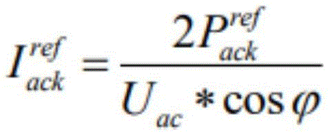
其中,

直流端电压参考值的确定公式如下:The formula for determining the reference value of the DC terminal voltage is as follows:

其中,

电流分配系数的确定公式如下:The formula for determining the current distribution coefficient is as follows:

Qk为任意一相子装置储能子模块电池组的总容量和Qall为总容量。Q k is the total capacity of any one-phase sub-device energy storage sub-module battery pack and Q all is the total capacity.
换流功率的转换公式如下:The conversion formula of commutation power is as follows:

其中,


每个桥臂的电流参考值的确定公式如下:The formula for determining the current reference value of each bridge arm is as follows:

其中,


如图7所示,储能子模块电容处电压约为500V,电池组端电压约为125V,则电压输出增益了4倍,,传统半桥子模块的电容电压达到500V,需要在电容处并联500V电池组,而本发明的储能子模块拓扑只需125V就能达到要求,这大大减少了电池组需要串联子电池的个数,从而提高了电池组运行的可靠性。As shown in Figure 7, the voltage at the capacitor of the energy storage sub-module is about 500V, and the voltage at the terminal of the battery pack is about 125V, so the voltage output gain is 4 times. The capacitor voltage of the traditional half-bridge sub-module reaches 500V, which needs to be connected in parallel at the capacitor. 500V battery pack, and the energy storage sub-module topology of the present invention only needs 125V to meet the requirements, which greatly reduces the number of sub-battery that needs to be connected in series in the battery pack, thereby improving the reliability of the battery pack operation.
如图8所示,记录了0-0.4秒的交流侧相电压波形,相电压为峰值约54KV左右的正弦波,因为每个桥臂连接50个子模块,则MMC变换器为51电平变换器,产生的交流波形趋于正弦波,谐波特性较好。As shown in Figure 8, the AC side phase voltage waveform of 0-0.4 seconds is recorded, and the phase voltage is a sine wave with a peak value of about 54KV. Because each bridge arm is connected to 50 sub-modules, the MMC converter is a 51-level converter , the generated AC waveform tends to be a sine wave, and the harmonic characteristics are better.
如图9所示,记录了0-2.5秒直流端负载的电压波形。直流电压在0.7秒后稳定在135KV左右,电压稳定性较好。As shown in Figure 9, the voltage waveform of the DC terminal load was recorded for 0-2.5 seconds. The DC voltage is stable at about 135KV after 0.7 seconds, and the voltage stability is good.
本发明能有效减小电池组所需的端电压,电池组串联电池数量减少,从而提高了电池的可靠性,因为储能子模块中具备锂电池组,无需考虑电容电压平衡策略,并提供了稳定直流母线电压,控制了每一桥臂输入或输出的功率,提高了子模块中电池组运行的可靠性。The invention can effectively reduce the terminal voltage required by the battery pack and reduce the number of batteries connected in series in the battery pack, thereby improving the reliability of the battery. The DC bus voltage is stabilized, the input or output power of each bridge arm is controlled, and the reliability of the operation of the battery pack in the sub-module is improved.
本领域内的技术人员应明白,本申请的实施例可提供为方法、系统、或计算机程序产品。因此,本申请可采用完全硬件实施例、完全软件实施例、或结合软件和硬件方面的实施例的形式。而且,本申请可采用在一个或多个其中包含有计算机可用程序代码的计算机可用存储介质(包括但不限于磁盘存储器、CD-ROM、光学存储器等)上实施的计算机程序产品的形式。本申请实施例中的方案可以采用各种计算机语言实现,例如,面向对象的程序设计语言Java和直译式脚本语言JavaScript等。As will be appreciated by those skilled in the art, the embodiments of the present application may be provided as a method, a system, or a computer program product. Accordingly, the present application may take the form of an entirely hardware embodiment, an entirely software embodiment, or an embodiment combining software and hardware aspects. Furthermore, the present application may take the form of a computer program product embodied on one or more computer-usable storage media (including, but not limited to, disk storage, CD-ROM, optical storage, etc.) having computer-usable program code embodied therein. The solutions in the embodiments of the present application may be implemented in various computer languages, for example, the object-oriented programming language Java and the literal translation scripting language JavaScript, and the like.
本申请是参照根据本申请实施例的方法、设备(系统)、和计算机程序产品的流程图和/或方框图来描述的。应理解可由计算机程序指令实现流程图和/或方框图中的每一流程和/或方框、以及流程图和/或方框图中的流程和/或方框的结合。可提供这些计算机程序指令到通用计算机、专用计算机、嵌入式处理机或其他可编程数据处理设备的处理器以产生一个机器,使得通过计算机或其他可编程数据处理设备的处理器执行的指令产生用于实现在流程图一个流程或多个流程和/或方框图一个方框或多个方框中指定的功能的装置。The present application is described with reference to flowchart illustrations and/or block diagrams of methods, apparatus (systems), and computer program products according to embodiments of the present application. It will be understood that each flow and/or block in the flowchart illustrations and/or block diagrams, and combinations of flows and/or blocks in the flowchart illustrations and/or block diagrams, can be implemented by computer program instructions. These computer program instructions may be provided to the processor of a general purpose computer, special purpose computer, embedded processor or other programmable data processing device to produce a machine such that the instructions executed by the processor of the computer or other programmable data processing device produce Means for implementing the functions specified in a flow or flow of a flowchart and/or a block or blocks of a block diagram.
这些计算机程序指令也可存储在能引导计算机或其他可编程数据处理设备以特定方式工作的计算机可读存储器中,使得存储在该计算机可读存储器中的指令产生包括指令装置的制造品,该指令装置实现在流程图一个流程或多个流程和/或方框图一个方框或多个方框中指定的功能。These computer program instructions may also be stored in a computer-readable memory capable of directing a computer or other programmable data processing apparatus to function in a particular manner, such that the instructions stored in the computer-readable memory result in an article of manufacture comprising instruction means, the instructions The apparatus implements the functions specified in the flow or flow of the flowcharts and/or the block or blocks of the block diagrams.
这些计算机程序指令也可装载到计算机或其他可编程数据处理设备上,使得在计算机或其他可编程设备上执行一系列操作步骤以产生计算机实现的处理,从而在计算机或其他可编程设备上执行的指令提供用于实现在流程图一个流程或多个流程和/或方框图一个方框或多个方框中指定的功能的步骤。These computer program instructions can also be loaded on a computer or other programmable data processing device to cause a series of operational steps to be performed on the computer or other programmable device to produce a computer-implemented process such that The instructions provide steps for implementing the functions specified in the flow or blocks of the flowcharts and/or the block or blocks of the block diagrams.
尽管已描述了本申请的优选实施例,但本领域内的技术人员一旦得知了基本创造性概念,则可对这些实施例作出另外的变更和修改。所以,所附权利要求意欲解释为包括优选实施例以及落入本申请范围的所有变更和修改。While the preferred embodiments of the present application have been described, additional changes and modifications to these embodiments may occur to those skilled in the art once the basic inventive concepts are known. Therefore, the appended claims are intended to be construed to include the preferred embodiment and all changes and modifications that fall within the scope of this application.
显然,本领域的技术人员可以对本申请进行各种改动和变型而不脱离本申请的精神和范围。这样,倘若本申请的这些修改和变型属于本申请权利要求及其等同技术的范围之内,则本申请也意图包含这些改动和变型在内。Obviously, those skilled in the art can make various changes and modifications to the present application without departing from the spirit and scope of the present application. Thus, if these modifications and variations of the present application fall within the scope of the claims of the present application and their equivalents, the present application is also intended to include these modifications and variations.
Claims (9)


Priority Applications (1)
| Application Number | Priority Date | Filing Date | Title |
|---|---|---|---|
| CN202010610474.3A CN111934572B (en) | 2020-06-29 | 2020-06-29 | Super-large-scale energy storage MMC converter device and energy storage control method |
Applications Claiming Priority (1)
| Application Number | Priority Date | Filing Date | Title |
|---|---|---|---|
| CN202010610474.3A CN111934572B (en) | 2020-06-29 | 2020-06-29 | Super-large-scale energy storage MMC converter device and energy storage control method |
Publications (2)
| Publication Number | Publication Date |
|---|---|
| CN111934572A CN111934572A (en) | 2020-11-13 |
| CN111934572B true CN111934572B (en) | 2022-10-04 |
Family
ID=73317482
Family Applications (1)
| Application Number | Title | Priority Date | Filing Date |
|---|---|---|---|
| CN202010610474.3A Active CN111934572B (en) | 2020-06-29 | 2020-06-29 | Super-large-scale energy storage MMC converter device and energy storage control method |
Country Status (1)
| Country | Link |
|---|---|
| CN (1) | CN111934572B (en) |
Families Citing this family (1)
| Publication number | Priority date | Publication date | Assignee | Title |
|---|---|---|---|---|
| CN116995712B (en) * | 2023-09-25 | 2024-01-30 | 广州三晶电气股份有限公司 | Energy control method and device for energy storage converter |
Citations (5)
| Publication number | Priority date | Publication date | Assignee | Title |
|---|---|---|---|---|
| WO2012024984A1 (en) * | 2010-07-22 | 2012-03-01 | 荣信电力电子股份有限公司 | Modular multilevel converter-based transformerless battery energy storage topology |
| CN103236706A (en) * | 2013-04-23 | 2013-08-07 | 中国科学院电工研究所 | Battery energy storage system based on modular multilevel AC-AC (Alternating Current-Alternating Current) converter topology |
| CN104113082A (en) * | 2014-07-17 | 2014-10-22 | 西安交通大学 | Modular full direct current photovoltaic system and control method thereof |
| CN204928610U (en) * | 2015-08-14 | 2015-12-30 | 国家电网公司 | Single -phase non - isolated form photovoltaic grid -connected inverter |
| CN106877371A (en) * | 2017-03-30 | 2017-06-20 | 上海交通大学 | A control method for a modular multilevel converter with energy storage function |
-
2020
- 2020-06-29 CN CN202010610474.3A patent/CN111934572B/en active Active
Patent Citations (5)
| Publication number | Priority date | Publication date | Assignee | Title |
|---|---|---|---|---|
| WO2012024984A1 (en) * | 2010-07-22 | 2012-03-01 | 荣信电力电子股份有限公司 | Modular multilevel converter-based transformerless battery energy storage topology |
| CN103236706A (en) * | 2013-04-23 | 2013-08-07 | 中国科学院电工研究所 | Battery energy storage system based on modular multilevel AC-AC (Alternating Current-Alternating Current) converter topology |
| CN104113082A (en) * | 2014-07-17 | 2014-10-22 | 西安交通大学 | Modular full direct current photovoltaic system and control method thereof |
| CN204928610U (en) * | 2015-08-14 | 2015-12-30 | 国家电网公司 | Single -phase non - isolated form photovoltaic grid -connected inverter |
| CN106877371A (en) * | 2017-03-30 | 2017-06-20 | 上海交通大学 | A control method for a modular multilevel converter with energy storage function |
Also Published As
| Publication number | Publication date |
|---|---|
| CN111934572A (en) | 2020-11-13 |
Similar Documents
| Publication | Publication Date | Title |
|---|---|---|
| CN109391166B (en) | A conversion circuit, control method and power supply equipment | |
| US9966777B2 (en) | Modular multilevel converter for hybrid energy storage | |
| AU2009344066B2 (en) | An arrangement for exchanging power | |
| US8508957B2 (en) | Power conversion device for converting DC power to AC power | |
| US8994216B2 (en) | Power conversion apparatus | |
| US9484835B2 (en) | Modified voltage source converter structure | |
| US9007792B2 (en) | Arrangement for transmitting power between a DC power line and an AC power line | |
| US10917019B2 (en) | Quasi-single stage power converter topology | |
| EP2443717B1 (en) | An arrangement for exchanging power | |
| AU2009348268A1 (en) | An arrangement for exchanging power | |
| CN103607131A (en) | Neutral point potential balancing control system and method of three-level inverter | |
| US20150357941A1 (en) | Voltage source converter comprising a chain-link converter | |
| WO2012041020A1 (en) | Single-phase five-level power converter | |
| CN105637755A (en) | Power conversion device | |
| Bhattacharya et al. | Power conversion systems enabled by sic bidfet device | |
| Wang et al. | X-type five-level current source inverter | |
| CN110224622B (en) | Sub-module capacitor voltage fluctuation suppression method for full-bridge modular multilevel converter | |
| CN102437761B (en) | Single-phase full bridge three-level inverter and three-phase three-level inverter | |
| CN111934572B (en) | Super-large-scale energy storage MMC converter device and energy storage control method | |
| Ansari et al. | A novel hybrid multilevel DC–DC converter employing trapezoidal modulation | |
| CN104883084A (en) | Neutral-point clamped cascade H-bridge hybrid multilevel converter | |
| US20210126554A1 (en) | Full-bridge inverter with unipolar switching scheme and its method of operation | |
| Wei et al. | A new quasi three-level hybrid modular multilevel converter | |
| Yuan | A new nine-switch non-regenerative four-level rectifier | |
| CN102427307B (en) | Three-phase four-wire three-level inverter |
Legal Events
| Date | Code | Title | Description |
|---|---|---|---|
| PB01 | Publication | ||
| PB01 | Publication | ||
| SE01 | Entry into force of request for substantive examination | ||
| SE01 | Entry into force of request for substantive examination | ||
| GR01 | Patent grant | ||
| GR01 | Patent grant |