CN111871711B - Adjustable oil coating machine for connecting piece of conveying pipeline - Google Patents
Adjustable oil coating machine for connecting piece of conveying pipeline Download PDFInfo
- Publication number
- CN111871711B CN111871711B CN202010519826.4A CN202010519826A CN111871711B CN 111871711 B CN111871711 B CN 111871711B CN 202010519826 A CN202010519826 A CN 202010519826A CN 111871711 B CN111871711 B CN 111871711B
- Authority
- CN
- China
- Prior art keywords
- coating
- fixedly connected
- adjacent
- mounting
- oil
- Prior art date
- Legal status (The legal status is an assumption and is not a legal conclusion. Google has not performed a legal analysis and makes no representation as to the accuracy of the status listed.)
- Active
Links
- 238000000576 coating method Methods 0.000 title claims abstract description 118
- 239000011248 coating agent Substances 0.000 title claims abstract description 116
- 238000005507 spraying Methods 0.000 claims description 23
- 230000006835 compression Effects 0.000 claims description 10
- 238000007906 compression Methods 0.000 claims description 10
- 238000002347 injection Methods 0.000 claims description 7
- 239000007924 injection Substances 0.000 claims description 7
- 230000005540 biological transmission Effects 0.000 claims description 6
- 230000008878 coupling Effects 0.000 description 9
- 238000010168 coupling process Methods 0.000 description 9
- 238000005859 coupling reaction Methods 0.000 description 9
- JEIPFZHSYJVQDO-UHFFFAOYSA-N iron(III) oxide Inorganic materials O=[Fe]O[Fe]=O JEIPFZHSYJVQDO-UHFFFAOYSA-N 0.000 description 7
- 238000000034 method Methods 0.000 description 7
- 230000002349 favourable effect Effects 0.000 description 5
- 235000017166 Bambusa arundinacea Nutrition 0.000 description 4
- 235000017491 Bambusa tulda Nutrition 0.000 description 4
- 241001330002 Bambuseae Species 0.000 description 4
- 235000015334 Phyllostachys viridis Nutrition 0.000 description 4
- 239000011425 bamboo Substances 0.000 description 4
- 238000010030 laminating Methods 0.000 description 4
- 239000007921 spray Substances 0.000 description 3
- 239000000463 material Substances 0.000 description 2
- 238000011084 recovery Methods 0.000 description 2
- 238000000926 separation method Methods 0.000 description 2
- XLYOFNOQVPJJNP-UHFFFAOYSA-N water Substances O XLYOFNOQVPJJNP-UHFFFAOYSA-N 0.000 description 2
- 229910001339 C alloy Inorganic materials 0.000 description 1
- 229910000975 Carbon steel Inorganic materials 0.000 description 1
- 229910000831 Steel Inorganic materials 0.000 description 1
- 238000007792 addition Methods 0.000 description 1
- 239000003570 air Substances 0.000 description 1
- 230000009286 beneficial effect Effects 0.000 description 1
- 239000010962 carbon steel Substances 0.000 description 1
- 230000003750 conditioning effect Effects 0.000 description 1
- 238000005260 corrosion Methods 0.000 description 1
- 230000007797 corrosion Effects 0.000 description 1
- 238000012986 modification Methods 0.000 description 1
- 230000004048 modification Effects 0.000 description 1
- 230000003449 preventive effect Effects 0.000 description 1
- 230000002035 prolonged effect Effects 0.000 description 1
- 239000013535 sea water Substances 0.000 description 1
- 239000002689 soil Substances 0.000 description 1
- 239000000243 solution Substances 0.000 description 1
- 239000010959 steel Substances 0.000 description 1
- 238000006467 substitution reaction Methods 0.000 description 1
Images


Classifications
-
- B—PERFORMING OPERATIONS; TRANSPORTING
- B05—SPRAYING OR ATOMISING IN GENERAL; APPLYING FLUENT MATERIALS TO SURFACES, IN GENERAL
- B05C—APPARATUS FOR APPLYING FLUENT MATERIALS TO SURFACES, IN GENERAL
- B05C7/00—Apparatus specially designed for applying liquid or other fluent material to the inside of hollow work
- B05C7/06—Apparatus specially designed for applying liquid or other fluent material to the inside of hollow work by devices moving in contact with the work
- B05C7/08—Apparatus specially designed for applying liquid or other fluent material to the inside of hollow work by devices moving in contact with the work for applying liquids or other fluent materials to the inside of tubes
-
- B—PERFORMING OPERATIONS; TRANSPORTING
- B05—SPRAYING OR ATOMISING IN GENERAL; APPLYING FLUENT MATERIALS TO SURFACES, IN GENERAL
- B05C—APPARATUS FOR APPLYING FLUENT MATERIALS TO SURFACES, IN GENERAL
- B05C1/00—Apparatus in which liquid or other fluent material is applied to the surface of the work by contact with a member carrying the liquid or other fluent material, e.g. a porous member loaded with a liquid to be applied as a coating
- B05C1/02—Apparatus in which liquid or other fluent material is applied to the surface of the work by contact with a member carrying the liquid or other fluent material, e.g. a porous member loaded with a liquid to be applied as a coating for applying liquid or other fluent material to separate articles
- B05C1/022—Apparatus in which liquid or other fluent material is applied to the surface of the work by contact with a member carrying the liquid or other fluent material, e.g. a porous member loaded with a liquid to be applied as a coating for applying liquid or other fluent material to separate articles to the outer surface of hollow articles
-
- B—PERFORMING OPERATIONS; TRANSPORTING
- B05—SPRAYING OR ATOMISING IN GENERAL; APPLYING FLUENT MATERIALS TO SURFACES, IN GENERAL
- B05C—APPARATUS FOR APPLYING FLUENT MATERIALS TO SURFACES, IN GENERAL
- B05C13/00—Means for manipulating or holding work, e.g. for separate articles
- B05C13/02—Means for manipulating or holding work, e.g. for separate articles for particular articles
Landscapes
- Spray Control Apparatus (AREA)
Abstract
The invention belongs to the technical field of pipeline oiling, and particularly relates to an adjustable oil coating machine for a connecting piece of a conveying pipeline, which comprises a workbench and a coating module; a rectangular through hole is formed in the middle of the top plate of the workbench; according to the invention, two coating modules are arranged, the distance between the two coating modules can be adjusted through the air cylinder, the rotation of the two coating modules can be controlled through the motor, the mounting frames between the adjacent first mounting plate and the second mounting plate are kept away from each other by utilizing the torsion spring between the air cylinder and the mounting frame and between the air cylinder and the connecting seat, the outer side wall of the pipeline connecting piece is oiled by utilizing the outer coating roller, the inner side wall of the pipeline connecting piece is in contact with the inner side wall of the pipeline connecting piece through the elastic coating roller on the mounting frame, the inner side wall and the outer side wall of the pipeline connecting piece are oiled, and the inner side wall of the pipeline connecting piece is oiled by utilizing the rotating mounting frame to drive the elastic coating sleeve to rotate, so that the efficiency of oiling the inner side and the outer side of the pipeline connecting piece is improved.
Description
Technical Field
The invention relates to the technical field of pipeline oiling, in particular to an adjustable oiling machine for a connecting piece of a conveying pipeline.
Background
A common corrosion for valve lines is that of carbon steel and low carbon alloy steels. The pipeline connecting piece is generally used for connecting the pipeline and the pipeline valve at the connecting position, and whether the valve pipeline is laid on the ground, underground or underwater (including seabed), the pipeline is corroded by external air, soil, water (particularly seawater) to the outer wall of the pipeline connecting piece, and the conveying medium corrodes to the inner wall of the pipeline connecting piece. Therefore, when the pipeline connecting piece is machined, pipeline oiling operation needs to be carried out on the inner wall and the outer wall of the pipeline connecting piece, and therefore the service life of the pipeline connecting piece is prolonged.
However, the existing part of the pipeline connecting pieces are coated manually in the oil coating process, and the inner wall and the outer wall of the pipeline connecting pieces are sequentially treated, so that the oil coating efficiency of the pipeline connecting pieces is reduced.
Disclosure of Invention
In order to overcome the technical problems, the invention aims to provide an adjustable oil coating machine for a conveying pipeline connecting piece, which is provided with two coating modules, wherein the distance between the two coating modules can be adjusted through an air cylinder, the rotation of the two coating modules can be controlled through a motor, a torsion spring between the air cylinder and a mounting frame and a connecting seat is utilized to enable the mounting frame between the adjacent first mounting plate and the second mounting plate to be far away from each other, an elastic coating sleeve is enabled to be opened to be in contact with the side edges of the two outer coating rollers, rust-proof oil is conveniently coated on the two outer coating rollers, the two coating modules are pushed by the air cylinder to be arranged at the inner side of the pipeline connecting piece to be close to the two second mounting plates, the outer side wall of the pipeline connecting piece is coated with oil through the outer coating rollers, and the elastic coating rollers on the mounting frame are in contact with the inner side wall of the pipeline connecting piece, realize that pipe connecting piece inside wall and lateral wall all carry out the fat liquoring, and utilize pivoted mounting bracket to drive the rotation of elastic coating cover and carry out the fat liquoring to pipe connecting piece's inside wall, be favorable to improving the fat liquoring efficiency of pipe connecting piece inside and outside.
The purpose of the invention can be realized by the following technical scheme:
an adjustable oil coating machine for a connecting piece of a conveying pipeline comprises a workbench and a coating module; a rectangular through hole is formed in the middle of the top plate of the workbench, two outer coating rollers which are parallel to each other are rotatably connected to the inner side of the rectangular through hole, a vertical plate is fixedly connected to one side, located on the rectangular through hole, of the top of the workbench, two adjusting modules are symmetrically arranged at two ends, located on two sides of the rectangular through hole, of the top of the workbench, and coating modules are arranged at the adjacent ends of the two adjusting modules;
the adjusting module comprises an air cylinder and a driving unit; one end of the air cylinder is fixedly connected with the top of the workbench through a fixing plate, the output end of the air cylinder is in transmission connection with a support frame, and the bottom of the support frame is provided with a sliding chute in sliding connection with a guide rail fixedly connected with the top of the workbench; the driving unit comprises a motor; the motor is fixedly connected to one end of the top of the support frame, and the output end of the motor is in transmission connection with a first bevel gear;
the coating module comprises a first mounting disc and a second mounting disc; the center of a circle of the first mounting plate is rotatably connected with a horizontally arranged oil spraying cylinder through a bearing, one end of the oil spraying cylinder is fixedly connected with the other end of the top of the adjacent support frame, one end of the oil spraying cylinder is communicated with a connecting hose for oil transportation, one side of the first mounting plate adjacent to the second mounting plate is fixedly connected with a plurality of connecting seats in an annular shape at equal angles, the inner sides of the connecting seats are movably connected with torsion springs, and a mounting frame is rotatably connected between two rotating seats on the same horizontal line through the torsion springs; elastic coating sleeves are fixedly sleeved on the outer sides of the mounting racks; one side of the first mounting plate, which is adjacent to the motor, is fixedly connected with a third bevel gear, and one end of an oil spraying cylinder, which is adjacent to the third bevel gear, is rotatably connected with a second bevel gear, wherein the second bevel gear is meshed with the first bevel gear and the third bevel gear at corresponding positions; one end of the oil spraying cylinder, which is adjacent to the motor, is positioned on the inner side of the third bevel gear; when the device is used, a controller can be arranged in a workbench, the controller is utilized to control the starting and stopping of the motor and the cylinder, the cylinder is communicated with an external air pump, the output ends of the two cylinders are controlled to be close to each other by the controller until the two second mounting plates are contacted with each other, the output ends of the cylinders are continuously pushed to move, the mounting frames between the two adjacent mounting plates are kept away from each other by a torsion spring between the mounting frame and the connecting seat, so that the elastic coating sleeve is opened to be contacted with the side edges of the two outer coating rollers, at the moment, the motor is controlled to rotate by the controller, the first bevel gear drives the third bevel gear to rotate by the second bevel gear, the first mounting plate can be driven to rotate, meanwhile, the oil spraying cylinder is communicated with an external oil pump by the connecting hose, a proper amount of anti-rust oil is added into the oil spraying cylinder by the external oil pump, and the position of the oil spraying cylinder is kept unchanged by the bearing, the elastic coating sleeve can be enabled to rotate after being contacted with the two outer coating rollers, so that anti-rust oil can be conveniently coated on the two outer coating rollers, then the output ends of the two cylinders contract, the pipeline connecting piece is arranged on the two outer coating rollers, the two coating modules are arranged on the inner side of the pipeline connecting piece to enable the two second mounting plates to be close to each other until the elastic coating rollers on the mounting frame are abutted against the inner side wall of the pipeline connecting piece, the driving motor rotates, the pipeline connecting piece rotates by utilizing the mounting frame abutted against the pipeline connecting piece and the elastic coating sleeve, the outer side wall of the pipeline connecting piece is coated with oil by utilizing the two outer coating rollers rotating along with the rotation of the pipeline connecting piece, then the two first mounting plates are enabled to be away from each other by a proper distance through the controller until the elastic coating rollers on the mounting frame are contacted with the inner side wall of the pipeline connecting piece, at the moment, the motor drives the first mounting frame to rotate, the elastic coating sleeve is utilized to coat the oil on the inner side wall of the pipeline connecting piece, the efficiency of the inside and outside fat liquoring of pipe connection spare is favorable to improving, and at the in-process of fat liquoring, the interior leading-in right amount of antirust oil to the oil spout section of thick bamboo of intermittent type, the antirust oil of being convenient for is through the blowout of oil spout section of thick bamboo, improves the quality of fat liquoring.
Further, the method comprises the following steps: the mounting rack comprises a first connecting rod; one side of each of two ends of the first connecting rod is provided with a sliding groove, one end of each of two adjacent sliding grooves, which is far away from each other, is fixedly connected with a compression spring, one side of the first connecting rod is slidably connected with one end of a third connecting rod through the two sliding grooves, the other ends of the two third connecting rods are rotatably connected with rotating seats, and the other ends of the two third connecting rods are fixedly connected with the compression springs at corresponding positions; one ends of the two rotating seats, which are deviated from each other, are rotatably connected with one ends of the second connecting rods, and the other ends of the two second connecting rods are rotatably connected with the adjacent connecting seats; after two second mounting discs contact, the output of cylinder continues to promote, make adjacent first mounting disc and second mounting disc be close to each other, at this moment, No. two connecting rods open to the direction of keeping away from two mounting disc centre of a circle, and then the inboard slip of the one end at the spout that can promote No. three connecting rods, promote a plurality of connecting rods between two mounting discs when No. three connecting rods slip and keep away from each other, and then can adjust the interval between a plurality of connecting rods, be convenient for be applicable to the conduit coupling piece of different internal meridians, and utilize compression spring can make the elastic coating cover on a connecting rod contact with conduit coupling piece's inside wall, improve fat liquoring efficiency.
Further, the method comprises the following steps: one end of the torsion spring is fixedly connected with one end of the adjacent connecting seat, and the other end of the torsion spring is fixedly connected with the other end of the adjacent second connecting rod; utilize torsion spring to make when adjacent first mounting disc and second mounting disc are close to each other, No. two connecting rods open to the direction of keeping away from two mounting disc centre of a circle to can be convenient for adjust the position of a connecting rod, make the outside of elastic coating cover and pipeline connecting piece's inside wall laminating, be favorable to improving fat liquoring efficiency.
Further, the method comprises the following steps: the length of the first connecting rod in contact with the second connecting rod is equal to one half of the length of the second connecting rod, and the length of the first connecting rod is the same as that of the elastic coating sleeve; utilize the length that a connecting rod and No. two connecting rods contacted to equal the half of No. two connecting rod lengths, can make the clearance that lies in between the adjacent tip of two connecting rods on same water flat line in two coating modules like this reduce to can guarantee the homogeneity of conduit coupling inside wall fat liquoring.
Further, the method comprises the following steps: one end of the oil spraying cylinder, which is adjacent to the second mounting plate, is fixedly connected with a return spring, and one end of the return spring is fixedly connected with one side of the second mounting plate at the corresponding position; after two second mounting discs contacted each other and oil-coated the inside wall of pipe connecting piece, need resume two second mounting discs to the primary position, at this moment, can be convenient for make the first mounting disc and the second mounting disc interval that are in the workstation with one side resume to the primary position through reset spring to can guarantee the adjacent lateral wall laminating of a connecting rod and No. two connecting rods, the recovery of a connecting rod of being convenient for guarantees all the other pipe connecting piece separation, and it is convenient to use.
Further, the method comprises the following steps: the rotation directions of the two coating modules are the same; through the rotation direction of adjusting two motors for two second mounting discs that contact each other rotate in step, it is convenient to use.
The invention has the beneficial effects that:
1. by arranging the two coating modules, adjusting the distance between the two coating modules through the air cylinder, controlling the rotation of the two coating modules through the motor, enabling the air cylinder and the torsion spring between the mounting frame and the connecting seat to enable the mounting frames between the adjacent first mounting plate and the second mounting plate to be far away from each other, enabling the elastic coating sleeve to be opened to be in contact with the side edges of the two outer coating rollers, facilitating the coating of antirust oil on the two outer coating rollers, pushing the two coating modules to be arranged at the inner side of the pipeline connecting piece to enable the two second mounting plates to be close to each other through the air cylinder, coating the outer side wall of the pipeline connecting piece through the outer coating sleeve, contacting the inner side wall of the pipeline connecting piece through the elastic coating roller on the mounting frame, coating the inner side wall and the outer side wall of the pipeline connecting piece, and coating the inner side wall of the pipeline connecting piece through driving the elastic coating roller to rotate through the rotating mounting frame, the efficiency of the fat liquoring of the inside and outside of the pipe connection spare is favorable to improving.
2. Through having seted up the spout on a connecting rod, utilize No. two connecting rods and No. three connecting rods rotation with spout sliding connection to be connected, be connected through torsion spring between No. three connecting rods and the connecting seat, can make a connecting rod open to the direction of keeping away from the first mounting disc centre of a circle like this, thereby can adjust the interval between a plurality of connecting rods, be convenient for be applicable to the conduit coupling spare of different internal meridians, and utilize compression spring can make the elastic coating cover on a connecting rod contact with conduit coupling spare's inside wall, improve fat liquoring efficiency.
Drawings
The invention will be further described with reference to the accompanying drawings.
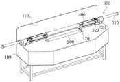
FIG. 1 is a perspective view of the present invention;
FIG. 2 is a schematic view of the positional relationship of the conditioning module and the coating module of the present invention;
FIG. 3 is an enlarged partial schematic view at A in FIG. 2;
FIG. 4 is a schematic structural view of a coating module according to the present invention;
fig. 5 is a schematic structural view of the mounting bracket of the present invention.
In the figure: 100. a work table; 110. a vertical plate; 120. a rectangular through hole; 200. an outer coating roll; 300. an adjustment module; 310. a cylinder; 311. a support frame; 320. a drive unit; 321. a motor; 322. a first bevel gear; 323. a second bevel gear; 324. a third bevel gear; 400. a coating module; 410. a first mounting plate; 420. a second mounting plate; 421. a return spring; 430. a mounting frame; 431. a first connecting rod; 4311. a chute; 4312. a compression spring; 432. a second connecting rod; 4321. a rotating seat; 433. a third connecting rod; 500. an oil spraying cylinder; 600. an elastic coating sleeve; 700. a connecting hose; 800. a torsion spring.
Detailed Description
The technical solutions in the embodiments of the present invention will be clearly and completely described below with reference to the embodiments of the present invention, and it is obvious that the described embodiments are only a part of the embodiments of the present invention, and not all of the embodiments. All other embodiments, which can be derived by a person skilled in the art from the embodiments given herein without making any creative effort, shall fall within the protection scope of the present invention.
Referring to fig. 1-5, an adjustable oil coater for connecting pieces of conveying pipes includes a work table 100 and a coating module 400; a rectangular through hole 120 is formed in the middle of the top plate of the workbench 100, two outer coating rollers 200 which are parallel to each other are rotatably connected to the inner side of the rectangular through hole 120, a vertical plate 110 is fixedly connected to one side, located at the rectangular through hole 120, of the top of the workbench 100, two adjusting modules 300 are symmetrically arranged at two ends, located at two sides of the rectangular through hole 120, of the top of the workbench 100, and coating modules 400 are arranged at two adjacent ends of each adjusting module 300;
wherein the adjusting module 300 includes a cylinder 310 and a driving unit 320; one end of the air cylinder 310 is fixedly connected with the top of the workbench 100 through a fixing plate, the output end of the air cylinder 310 is in transmission connection with a support frame 311, and the bottom of the support frame 311 is provided with a sliding groove 4311 in sliding connection with a guide rail fixedly connected with the top of the workbench 100; the driving unit 320 includes a motor 321; the motor 321 is fixedly connected to one end of the top of the support frame 311, and the output end of the motor 321 is in transmission connection with a first bevel gear 322;
the coating module 400 includes a first mounting plate 410 and a second mounting plate 420; the circle center of the first mounting plate 410 is rotatably connected with a horizontally arranged oil injection cylinder 500 through a bearing, one end of the oil injection cylinder 500 is fixedly connected with the other end of the top of the adjacent support frame 311, one end of the oil injection cylinder 500 is communicated with a connecting hose 700 for oil transportation, one side of the first mounting plate 410 adjacent to the second mounting plate 420 is fixedly connected with a plurality of connecting seats in an annular shape at equal angles, the inner sides of the connecting seats are movably connected with torsion springs 800, and a mounting frame 430 is rotatably connected between two rotating seats 4321 on the same horizontal line through the torsion springs 800; elastic coating sleeves 600 are fixedly sleeved on the outer sides of the mounting frames 430; one side of the first mounting plate 410, which is adjacent to the motor 321, is fixedly connected with a third bevel gear 324, and one end of one oil spraying cylinder 500, which is adjacent to the third bevel gear 324, is rotatably connected with a second bevel gear 323, wherein the second bevel gear 323 is meshed with the first bevel gear 322 and the third bevel gear 324 at corresponding positions; one end of the oil spraying barrel 500 adjacent to the motor 321 is positioned on the inner side of the third bevel gear 324; when the device is used, a controller can be arranged in the workbench 100, the controller is utilized to control the starting and stopping of the motor 321 and the cylinder 310, the cylinder 310 is communicated with an external air pump, the output ends of the two cylinders 310 are controlled to be close to each other by the controller until the two second mounting discs 420 contact with each other, the output ends of the cylinders 310 are continuously pushed to move, the mounting frames 430 between the two adjacent mounting discs are far away from each other by the torsion spring 800 between the mounting frame 430 and the connecting seat, so that the elastic coating sleeve 600 is opened to contact with the side edges of the two outer coating rollers 200, at the moment, the motor 321 is controlled to rotate by the controller, the first bevel gear 322 drives the third bevel gear 324 to rotate through the second bevel gear 323, the first mounting disc 410 can be driven to rotate, meanwhile, the oil spraying cylinder 500 is communicated with an external oil pump through the connecting hose 700, a proper amount of anti-rust oil is added into the oil spraying cylinder 500 through the outside, the bearing makes the position of the oil spraying cylinder 500 unchanged, so that the elastic coating sleeve 600 can rotate after contacting with the two outer coating rollers 200, so as to facilitate the coating of the anti-rust oil on the two outer coating rollers 200, then the output ends of the two cylinders 310 shrink, the pipeline connecting piece is placed on the two outer coating rollers 200, so that the two coating modules 400 are placed on the inner side of the pipeline connecting piece until the two second mounting discs 420 approach each other until the elastic coating rollers on the mounting frame 430 abut against the inner side wall of the pipeline connecting piece, the driving motor 321 rotates, the mounting frame 430 abutting against the pipeline connecting piece and the elastic coating sleeve 600 rotate to enable the pipeline connecting piece to rotate, the outer side wall of the pipeline connecting piece is oiled by the two outer coating rollers 200 rotating along with the pipeline connecting piece, then the two first mounting discs 410 are separated from each other by a proper distance through the controller, until the elastic coating sleeve 600 on the mounting frame 430 contacts with the inner side wall of the pipeline connecting piece, at this moment, the motor 321 drives the first mounting disc 410 to rotate, the rotating mounting frame 430 is utilized to drive the elastic coating roller to rotate to coat oil on the inner side wall of the pipeline connecting piece, the efficiency of coating oil on the inner side and the outer side of the pipeline connecting piece is improved, in the oil coating process, a proper amount of antirust oil is intermittently introduced into the oil spraying barrel 500 at intervals, the antirust oil is convenient to spray out through the oil spraying barrel 500, and the oil coating quality is improved.
The mounting bracket 430 includes a first connecting rod 431; one side of each of two ends of the first connecting rod is provided with a sliding groove 4311, one end of each of two adjacent sliding grooves 4311, which is far away from the first connecting rod, is fixedly connected with a compression spring 4312, one side of the first connecting rod is slidably connected with one end of a third connecting rod 433 through two sliding grooves 4311, the other ends of the two third connecting rods 433 are rotatably connected with a rotating seat 4321, and the other ends of the two third connecting rods 433 are fixedly connected with the compression springs 4312 at corresponding positions; one ends of the two rotating seats 4321, which are deviated from each other, are rotatably connected with one ends of the second connecting rods 432, and the other ends of the two second connecting rods 432 are rotatably connected with the adjacent connecting seats; after two second mounting discs 420 contact, the output of cylinder 310 continues to promote, make adjacent first mounting disc 410 and second mounting disc 420 be close to each other, at this moment, connecting rod 432 is opened to the direction of keeping away from two mounting disc centre of a circle No. two, and then the one end that can promote No. three connecting rod 433 slides in spout 4311's inboard, promote a plurality of connecting rod 431 between two mounting discs when No. three connecting rod 433 slides and keep away from each other, and then can adjust the interval between a plurality of connecting rod 431, be convenient for be applicable to the conduit coupling of different internal meridians, and utilize compression spring 4312 can make the contact of the inside wall of elastic coating cover 600 on connecting rod 431 with conduit coupling, improve fat liquoring efficiency.
One end of the torsion spring 800 is fixedly connected with one end of the adjacent connecting seat, and the other end of the torsion spring is fixedly connected with the other end of the adjacent second connecting rod 432; utilize torsion spring 800 to make when adjacent first mounting disc 410 and second mounting disc 420 are close to each other, No. two connecting rods 432 open to the direction of keeping away from two mounting disc centre of a circle to can be convenient for adjust the position of a connecting rod 431, make the outside of elastic coating cover 600 and the inside wall laminating of pipe connection spare, be favorable to improving fat liquoring efficiency.
The length of the contact between the first connecting rod 431 and the second connecting rod 432 is equal to one half of the length of the second connecting rod 432, and the length of the first connecting rod 431 is the same as that of the elastic coating sleeve 600; the length of the contact between the first connecting rod 431 and the second connecting rod 432 is equal to one half of the length of the second connecting rod 432, so that the gap between the adjacent ends of the two first connecting rods 431 on the same horizontal line in the two coating modules 400 is reduced, and the uniformity of oiling the inner side wall of the pipe connecting piece can be ensured.
One end of the oil injection cylinder 500 adjacent to the second mounting plate 420 is fixedly connected with a return spring 421, and one end of the return spring 421 is fixedly connected with one side of the second mounting plate 420 at the corresponding position; after finishing oiling to conduit coupling's inside wall after two second mounting discs 420 mutual contacts, need resume two second mounting discs 420 to the primary position, at this moment, can be convenient for make the first mounting disc 410 and the second mounting disc 420 interval that are in workstation 100 with one side resume to the primary position through reset spring 421, thereby can guarantee the laminating of the adjacent lateral wall of a connecting rod 431 and No. two connecting rods 432, be convenient for the recovery of a connecting rod 431, guarantee all the other conduit coupling separation, it is convenient to use.
The rotation directions of the two coating modules 400 are the same; the rotation directions of the two motors 321 are adjusted, so that the two second mounting discs 420 which are in contact with each other rotate synchronously, and the use is convenient.
The working principle is as follows: when the device is used, a controller can be arranged in the workbench 100, the controller is utilized to control the starting and stopping of the motor 321 and the cylinder 310, the cylinder 310 is communicated with an external air pump, the output ends of the two cylinders 310 are controlled to be close to each other by the controller until the two second mounting discs 420 contact with each other, the output ends of the cylinders 310 are continuously pushed to move, the mounting frames 430 between the two adjacent mounting discs are far away from each other by the torsion spring 800 between the mounting frame 430 and the connecting seat, so that the elastic coating sleeve 600 is opened to contact with the side edges of the two outer coating rollers 200, at the moment, the motor 321 is controlled to rotate by the controller, the first bevel gear 322 drives the third bevel gear 324 to rotate through the second bevel gear 323, the first mounting disc 410 can be driven to rotate, meanwhile, the oil spraying cylinder 500 is communicated with an external oil pump through the connecting hose 700, a proper amount of anti-rust oil is added into the oil spraying cylinder 500 through the outside, the rust preventive oil can be sprayed onto the elastic coating sleeve 600 through the oil spray holes uniformly formed on the oil spray cylinder 500, further, the oil can be supplemented to the elastic coating sleeve 600, the smooth oil coating operation is ensured, the position of the oil spraying cylinder 500 is not changed by the bearing, thus, the elastic coating sleeve 600 can rotate after contacting with the two outer coating rollers 200, so that the anti-rust oil can be conveniently coated on the two outer coating rollers 200, then, the output ends of the two cylinders 310 are contracted, the pipe connection is placed on the two outer coating rolls 200, the two coating modules 400 are arranged on the inner side of the pipeline connecting piece until the two second mounting discs 420 approach each other until the elastic coating rollers on the mounting frame 430 are tightly abutted against the inner side wall of the pipeline connecting piece, the driving motor 321 rotates, the pipeline connecting piece is enabled to rotate by the mounting frame 430 tightly abutted against the pipeline connecting piece and the elastic coating sleeve 600, and the outer side wall of the pipeline connecting piece is coated with oil by the two outer coating rollers 200 rotating along with the rotation of the pipeline connecting piece;
make two first mounting discs 410 keep away from suitable distance each other through the controller, elasticity coating roll on to mounting bracket 430 contacts with pipe connection's inside wall, motor 321 drives first mounting disc 410 and rotates this moment, utilize pivoted mounting bracket 430 to drive elasticity coating roll and rotate and carry out the fat liquoring to pipe connection's inside wall, and at the in-process of fat liquoring, the intermittent type is to the leading-in appropriate amount of antirust oil in the inside of oil spout section of thick bamboo 500, the antirust oil of being convenient for is through the blowout of oil spout section of thick bamboo 500 blowout.
In the description herein, references to the description of "one embodiment," "an example," "a specific example" or the like are intended to mean that a particular feature, structure, material, or characteristic described in connection with the embodiment or example is included in at least one embodiment or example of the invention. In this specification, the schematic representations of the terms used above do not necessarily refer to the same embodiment or example. Furthermore, the particular features, structures, materials, or characteristics described may be combined in any suitable manner in any one or more embodiments or examples.
The foregoing is illustrative and explanatory only and is not intended to be exhaustive or to limit the invention to the precise embodiments described, and various modifications, additions, and substitutions may be made by those skilled in the art without departing from the scope of the invention or exceeding the scope of the claims.
Claims (6)
1. The adjustable oil coating machine for the connecting piece of the conveying pipeline is characterized by comprising a workbench (100) and a coating module (400); a rectangular through hole (120) is formed in the middle of a top plate of the workbench (100), two outer coating rollers (200) which are parallel to each other are rotatably connected to the inner side of the rectangular through hole (120), a vertical plate (110) is fixedly connected to one side, located on the rectangular through hole (120), of the top of the workbench (100), two adjusting modules (300) are symmetrically arranged at two ends, located on two sides of the rectangular through hole (120), of the top of the workbench (100), and coating modules (400) are arranged at one adjacent ends of the two adjusting modules (300);
wherein the adjusting module (300) comprises a cylinder (310) and a driving unit (320); one end of the air cylinder (310) is fixedly connected with the top of the workbench (100) through a fixing plate, the output end of the air cylinder (310) is in transmission connection with a support frame (311), and the bottom of the support frame (311) is provided with a sliding groove (4311) in sliding connection with a guide rail fixedly connected with the top of the workbench (100); the drive unit (320) comprises a motor (321); the motor (321) is fixedly connected to one end of the top of the support frame (311), and the output end of the motor (321) is in transmission connection with a first bevel gear (322);
the coating module (400) comprises a first mounting plate (410) and a second mounting plate (420); the center of a circle of the first mounting disc (410) is rotatably connected with a horizontally arranged oil injection cylinder (500) through a bearing, one end of the oil injection cylinder (500) is fixedly connected with the other end of the top of the adjacent support frame (311), one end of the oil injection cylinder (500) is communicated with a connecting hose (700) for oil transportation, one side, adjacent to the second mounting disc (420), of the first mounting disc (410) is fixedly connected with a plurality of connecting seats in an annular shape at equal angles, the inner sides of the connecting seats are movably connected with torsion springs (800), and a mounting frame (430) is rotatably connected between two rotating seats (4321) located on the same horizontal line through the torsion springs (800); elastic coating sleeves (600) are fixedly sleeved on the outer sides of the mounting frames (430); one side of the first mounting disc (410), which is adjacent to the motor (321), is fixedly connected with a third bevel gear (324), and one end of an oil spraying cylinder (500), which is adjacent to the third bevel gear (324), is rotatably connected with a second bevel gear (323), wherein the second bevel gear (323) is meshed with the first bevel gear (322) and the third bevel gear (324) at corresponding positions; one end of the oil spraying cylinder (500) adjacent to the motor (321) is positioned on the inner side of the third bevel gear (324).
2. The adjustable conveyor pipe connector oiling machine as defined in claim 1, wherein the mounting bracket (430) comprises a first connecting rod (431); one side of each of two ends of the first connecting rod is provided with a sliding groove (4311), one end of each of two adjacent sliding grooves (4311) which are deviated from each other is fixedly connected with a compression spring (4312), one side of the first connecting rod is slidably connected with one end of a third connecting rod (433) through the two sliding grooves (4311), the other ends of the two third connecting rods (433) are rotatably connected with a rotating seat (4321), and the other ends of the two third connecting rods (433) are fixedly connected with the compression springs (4312) at corresponding positions; two the one end that rotates seat (4321) and deviate from mutually all rotates the one end that is connected with No. two connecting rods (432), and the other end of two No. two connecting rods (432) all rotates with adjacent connecting seat and is connected.
3. The adjustable oil coating machine for the connecting pieces of the conveying pipelines is characterized in that one end of the torsion spring (800) is fixedly connected with one end of the adjacent connecting seat, and the other end of the torsion spring is fixedly connected with the other end of the adjacent second connecting rod (432).
4. The adjustable oil coating machine for the conveying pipeline connecting pieces is characterized in that the length of the contact between the first connecting rod (431) and the second connecting rod (432) is equal to one half of the length of the second connecting rod (432), and the length of the first connecting rod (431) is equal to the length of the elastic coating sleeve (600).
5. The adjustable oil coating machine for the connecting pieces of the conveying pipelines is characterized in that one end, adjacent to the second mounting plate (420), of the oil spraying cylinder (500) is fixedly connected with a return spring (421), and one end of the return spring (421) is fixedly connected with one side of the second mounting plate (420) at the corresponding position.
6. The adjustable oil coater for connecting pieces of conveying pipes according to claim 1, wherein the two coating modules (400) rotate in the same direction.
Priority Applications (1)
| Application Number | Priority Date | Filing Date | Title |
|---|---|---|---|
| CN202010519826.4A CN111871711B (en) | 2020-06-09 | 2020-06-09 | Adjustable oil coating machine for connecting piece of conveying pipeline |
Applications Claiming Priority (1)
| Application Number | Priority Date | Filing Date | Title |
|---|---|---|---|
| CN202010519826.4A CN111871711B (en) | 2020-06-09 | 2020-06-09 | Adjustable oil coating machine for connecting piece of conveying pipeline |
Publications (2)
| Publication Number | Publication Date |
|---|---|
| CN111871711A CN111871711A (en) | 2020-11-03 |
| CN111871711B true CN111871711B (en) | 2021-10-01 |
Family
ID=73156503
Family Applications (1)
| Application Number | Title | Priority Date | Filing Date |
|---|---|---|---|
| CN202010519826.4A Active CN111871711B (en) | 2020-06-09 | 2020-06-09 | Adjustable oil coating machine for connecting piece of conveying pipeline |
Country Status (1)
| Country | Link |
|---|---|
| CN (1) | CN111871711B (en) |
Families Citing this family (3)
| Publication number | Priority date | Publication date | Assignee | Title |
|---|---|---|---|---|
| CN112619952B (en) * | 2020-11-16 | 2023-01-24 | 重庆大学 | Spraying robot shoulder joint |
| CN114602692B (en) * | 2022-03-16 | 2023-04-07 | 界首市兴隆渔具有限公司 | A fishing rod paint spraying apparatus for fishing tackle production |
| CN115445847A (en) * | 2022-10-28 | 2022-12-09 | 珠海格力智能装备有限公司 | Oiling mechanism and disc tube film production equipment |
Family Cites Families (11)
| Publication number | Priority date | Publication date | Assignee | Title |
|---|---|---|---|---|
| US8282981B2 (en) * | 2008-06-24 | 2012-10-09 | Abbott Cardiovascular Systems Inc. | Method and system for selective coating of endoluminal prostheses |
| KR101474991B1 (en) * | 2013-08-01 | 2014-12-19 | 삼성중공업 주식회사 | Pipe Painting Apparatus |
| KR101505580B1 (en) * | 2013-08-01 | 2015-03-24 | 삼성중공업 주식회사 | Pipe Painting Apparatus |
| CN105944887B (en) * | 2016-06-16 | 2019-03-12 | 贵州盛红科技有限责任公司 | A kind of inner wall of the pipe mopping equipment and mopping method |
| CN106930707B (en) * | 2017-02-22 | 2019-01-18 | 中国石油大学(华东) | Hollow carbon fiber coiled rod connector and its automatic welding device |
| CN107282372A (en) * | 2017-07-27 | 2017-10-24 | 陈璐 | A kind of antirust oil painting device on the inside of building pipe |
| CN108212648A (en) * | 2017-12-19 | 2018-06-29 | 苏娜娜 | A kind of construction steel pipe oiling maintained equipment based on rack-and-pinion movement |
| CN108262220B (en) * | 2018-04-18 | 2020-06-09 | 唐天益 | A device for gluing the inner wall of a pipe |
| CN209476575U (en) * | 2019-01-10 | 2019-10-11 | 力德精密工业(深圳)有限公司 | Fully automatic shaft core gluing machine |
| CN109876975B (en) * | 2019-04-12 | 2020-10-30 | 江苏英斯坦福环境科技有限公司 | Automatic paint spraying device for inner wall of pipeline |
| CN111203368B (en) * | 2020-04-08 | 2020-11-13 | 日照锦湖金马化学有限公司 | Underground pipeline painting device |
-
2020
- 2020-06-09 CN CN202010519826.4A patent/CN111871711B/en active Active
Also Published As
| Publication number | Publication date |
|---|---|
| CN111871711A (en) | 2020-11-03 |
Similar Documents
| Publication | Publication Date | Title |
|---|---|---|
| CN111871711B (en) | Adjustable oil coating machine for connecting piece of conveying pipeline | |
| CN206296107U (en) | A kind of super cast iron tube outer surface Rustproofing apparatus | |
| CN110538750B (en) | Pipe diameter self-adaptation inner wall spraying equipment to heavy-calibre steel pipe | |
| CN110124930B (en) | A steel pipe oiling device | |
| CN116618440B (en) | Roll gap and roll temperature adjustable self-lubricating rolling device | |
| CN114308492A (en) | Rust removal and corrosion prevention device for steel pipe wall and using method | |
| CN116175073A (en) | Petrochemical pipeline processing equipment | |
| CN102059185A (en) | Device for coating steel rail and method thereof | |
| CN112387495A (en) | Outer wall spraying equipment for processing large-diameter arc-shaped pipe | |
| CN210024832U (en) | Automatic bellmouth cleaning and paint spraying device | |
| CN108031607B (en) | Rolling line oiling tool | |
| CN216447686U (en) | Corrosion prevention device for long-distance urban natural gas pipeline | |
| CN108246558B (en) | Surface coating device for columnar steel billet | |
| CN118925979B (en) | Anti-corrosion spraying equipment and method based on ship bottom plate | |
| CN119869822A (en) | Corrosion prevention treatment device and method for offshore wind power equipment | |
| CN210585527U (en) | Horizontal semi-automatic spraying machine | |
| CN113621785A (en) | Welding seam cooling device for stainless steel strip continuous annealing and pickling line | |
| CN219356645U (en) | Workpiece surface preservative coating equipment | |
| CN112934617A (en) | Roller coating processing system for aluminum coil | |
| CN215510468U (en) | Rust removal device for hydraulic engineering pipeline | |
| CN210079915U (en) | Bolt oiling station | |
| CN107597486B (en) | Spray coating method | |
| CN217165051U (en) | Rust removal and corrosion prevention device for steel pipe wall | |
| CN217289001U (en) | Heating and spraying integrated spraying device | |
| CN210675666U (en) | Oil gas field pipeline anticorrosion spraying device |
Legal Events
| Date | Code | Title | Description |
|---|---|---|---|
| PB01 | Publication | ||
| PB01 | Publication | ||
| SE01 | Entry into force of request for substantive examination | ||
| SE01 | Entry into force of request for substantive examination | ||
| TA01 | Transfer of patent application right |
Effective date of registration: 20210916 Address after: Room 1418, Lunda Jinling International, Beixin street, Tengzhou City, Zaozhuang City, Shandong Province, 277599 Applicant after: Tengzhou Weida Intelligent Technology Co.,Ltd. Address before: 510030 room 801, 18 he'an street, Xihua Road, Yuexiu District, Guangzhou City, Guangdong Province Applicant before: Liang Yunzhao |
|
| TA01 | Transfer of patent application right | ||
| GR01 | Patent grant | ||
| GR01 | Patent grant |